EP2273344A1 - Handheld mobile phone and method for resetting the handheld mobile phone thereof - Google Patents
Handheld mobile phone and method for resetting the handheld mobile phone thereof Download PDFInfo
- Publication number
- EP2273344A1 EP2273344A1 EP10006643A EP10006643A EP2273344A1 EP 2273344 A1 EP2273344 A1 EP 2273344A1 EP 10006643 A EP10006643 A EP 10006643A EP 10006643 A EP10006643 A EP 10006643A EP 2273344 A1 EP2273344 A1 EP 2273344A1
- Authority
- EP
- European Patent Office
- Prior art keywords
- button
- mobile phone
- handheld mobile
- buttons
- pressed
- Prior art date
- Legal status (The legal status is an assumption and is not a legal conclusion. Google has not performed a legal analysis and makes no representation as to the accuracy of the status listed.)
- Ceased
Links
Images





Classifications
-
- G—PHYSICS
- G06—COMPUTING OR CALCULATING; COUNTING
- G06F—ELECTRIC DIGITAL DATA PROCESSING
- G06F1/00—Details not covered by groups G06F3/00 - G06F13/00 and G06F21/00
- G06F1/24—Resetting means
-
- H—ELECTRICITY
- H04—ELECTRIC COMMUNICATION TECHNIQUE
- H04M—TELEPHONIC COMMUNICATION
- H04M1/00—Substation equipment, e.g. for use by subscribers
- H04M1/72—Mobile telephones; Cordless telephones, i.e. devices for establishing wireless links to base stations without route selection
- H04M1/724—User interfaces specially adapted for cordless or mobile telephones
- H04M1/72466—User interfaces specially adapted for cordless or mobile telephones with selection means, e.g. keys, having functions defined by the mode or the status of the device
Definitions
- the present disclosure relates to a handheld mobile phone and a related method for resetting the handheld mobile phone according to the pre-characterizing clauses of claims 1 and 10.
- the present invention aims at providing a handheld mobile phone and a related method for resetting the handheld mobile phone that not only can the cost and the space of a reset button be saved, but also can the problem that users cannot find a stylus or a tip-like object to sting the reset button in the prior art be solved.
- the claimed handheld mobile phone includes at least two buttons, a logic circuit, and a processing unit.
- Each button is used for performing at least one specific function.
- the logic circuit is coupled to the at least two buttons.
- the logic circuit generates a corresponding specific signal when one of the least two buttons is pressed alone, and generates at least a control signal when all of the at least two buttons are pressed.
- the processing unit is coupled to the logic circuit.
- the processing unit executes the specific function of the pressed button according to the corresponding specific signal, and controls the handheld mobile phone to enter a reset state from an operating state according to at least the control signal when all of the at least two buttons are pressed.
- the claimed method for resetting a handheld mobile phone includes the steps of: detecting pressed statuses of the at least two buttons; when one of the at least two buttons is pressed alone, generating a corresponding specific signal; executing the specific function of the pressed button according to the corresponding specific signal; when all of the at least two buttons are pressed, generating at least a control signal; and controlling the handheld mobile phone to enter a reset state from an operating state according to at least the control signal.
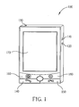
- FIG.1 is a perspective view of an illustrative handheld mobile phone 100 of the present disclosure
- FIG.2 is a diagram showing internal components of the handheld mobile phone 100 shown in FIG.1
- the appearance of the handheld mobile phone 100 includes a display panel 170 (or a touch panel) for displaying user information and a plurality of buttons, such as: a volume up button 110, a volume down button 120, a power button 130, a send button 140, an end button 150, a home button 160, and an OK button 180.
- the handheld mobile phone 100 includes, but is not limited to, at least two buttons, a logic circuit 210, a processing unit 220, a display panel 170, a random access memory (RAM) 230, a read only memory (ROM) 240, and a speaker 250.
- a logic circuit 210 a processing unit 220
- a display panel 170 a random access memory (RAM) 230
- a read only memory (ROM) 240 a speaker 250.
- three buttons A, B, and C are cited as an example for description of the present disclosure.
- Each of the buttons A, B, and C is used for performing at least one specific function.
- the specific function corresponding to a send button can be performed for making a phone call or answering an incoming call to establish a call connection when the handheld mobile phone 100 is in a standby state; the specific function corresponding to an end button can be performed for interrupting the call connection; the specific function corresponding to a volume up button can be performed for increasing the volume of the speaker 250; the specific function corresponding to a volume down button can be performed for lowering the volume of the speaker 250; the specific function corresponding to a home button can be performed for making the screen of the handheld mobile phone 100 return to a home page; the specific function corresponding to a power button can be performed for powering off the handheld mobile phone 100; and the specific function corresponding to an OK button can be performed for confirming a command or a program.
- the logic circuit 210 is coupled to the three buttons A, B, and C for detecting pressed statuses of at least two buttons of the three buttons A, B, and C.
- the logic circuit 210 When one of the three buttons A, B, and C is pressed alone, the logic circuit 210 generates a corresponding specific signal SD.
- the logic circuit 210 When at least two buttons among the three buttons A, B, and C are pressed, the logic circuit 210 generates an interrupt signal INT and a control signal SC.
- the processing unit 220 e.g. a central processing unit, CPU
- the processing unit 220 receives the specific signal SD via a transmission interface 222 (e.g.
- the processing unit 220 controls the handheld mobile phone 100 to enter a reset state SR from an operating state S0 according to the interrupt signal INT and the control signal SC.
- the aforementioned control signal is a reset signal. Therefore, when at least two buttons among the three buttons A, B, and C are pressed, the logic circuit 210 generates the interrupt signal INT to notify the processing unit 220 of storing the current system information and then generates the reset signal (i.e. the control signal SC) to the processing unit 220 after the interrupt signal INT is generated for a period of time T1.
- the processing unit 220 receives the reset signal, it controls the handheld mobile phone 100 to enter the reset state SR from the operating state S0. At this time, the processing unit 220 resets the handheld mobile phone 100.
- the processing unit 220 when the processing unit 220 resets the handheld mobile phone 100, the processing unit 220 clears the RAM 230 and then loads the embedded operating system 242 stored in the ROM 240 into the RAM 230 in order to complete the action of resetting the handheld mobile phone 100.
- the abovementioned logic circuit 210 and processing unit 220 can be integrated into an identical chip 260, but this should not be considered as limitations of the present disclosure.
- the processing unit 220 executes the specific function of the pressed button according to the corresponding specific signal SD; and when at least two buttons among the three buttons A, B, and C are pressed, the processing unit 220 resets the handheld mobile phone 100. Therefore, not only can the cost and the space for a reset button be saved, but also can the problem that users cannot find a "stylus" or a tip-like object to sting the reset button in the prior art be solved.
- buttons A, B, and C mentioned above are physical buttons of the handheld mobile phone 100, such as any one of the plurality of buttons 110 ⁇ 160 and 180 shown in FIG.1 . But this is presented merely for describing the present disclosure, and in no way should be considered to be limitations of the scope of the present disclosure. Furthermore, in the abovementioned embodiment, an example that at least two buttons among the three buttons A, B, and C are simultaneously pressed is cited for illustration, but this should not be considered as limitations of the present disclosure. The number of the pressed buttons is not limited.
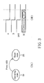
- FIG.3 it is directed to a condition that both of the two buttons are pressed without considerations of a pressed sequence of the pressed buttons.
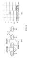
- FIG.4 it is directed to a condition that both of the two buttons are pressed with considerations of the pressed sequence of the pressed buttons.
- FIG.5 it is directed to a condition that all of the three buttons are pressed without considerations of the pressed sequence of the pressed buttons.
- FIG.6 it is directed to a condition that all of the three buttons are pressed with considerations of the pressed sequence of the pressed buttons.
- FIG.3 including 3A and 3B.
- the processing unit 220 controls the handheld mobile phone 100 to enter the reset state SR from the operating state S0.
- the high logic level "1" is used for representing a condition that the button A/B is not pressed
- the low logic level "0" is used for representing a condition that the button A/B is pressed.
- the logic circuit 210 sends the interrupt signal INT (which is represented by the low logic level “0") to the processing unit 220, and then sends the control signal SC (which is represented by the low logic level "0") to the processing unit 220 after the interrupt signal INT is generated for a period of time T1.
- the processing unit 220 receives the control signal SC, it controls the handheld mobile phone 100 to enter the resent state SR from the operating state S0.
- the abovementioned operating state S0 may include a normal operating state, a standby state, a sleeping state or a shut down state. If the user wants to reset the handheld mobile phone 100, this action can be easily completed by simultaneously pressing at least two buttons (e.g. the buttons A and B) among the three buttons A, B, and C.
- the operating state S0 is a standby state, in which the handheld mobile phone 100 is waiting to make a phone call or answer an incoming call so as to establish a call connection.
- FIG.4 including 4A and 4B.
- the processing unit 220 controls the handheld mobile phone 100 to enter a first state S1 from the operating state S0.
- the processing unit 220 controls the handheld mobile phone 100 to enter the reset state SR from the first state S1.
- the handheld mobile phone 100 after the handheld mobile phone 100 enters the first state S1, it will return back to the operating state S0 automatically if the user releases the button A at this time. Or it will enter the reset state SR if the user presses the button B at this time.
- the high logic level "1" is used for representing a condition that the button A/B is not pressed
- the low logic level "0" is used for representing a condition that the button A/B is pressed.
- the logic circuit 210 Only when the two buttons A and B are sequentially pressed, the logic circuit 210 sends the interrupt signal INT (which is represented by the low logic level “0") to the processing unit 220, and then sends the control signal SC (which is represented by the low logic level "0") to the processing unit 220 after the interrupt signal INT is generated for a period of time T1.
- the pre-defined pressed sequence of the pressed buttons i.e. A ⁇ B
- the action of resetting the handheld mobile phone 100 can be executed in order to avoid erroneous actions.
- the aforementioned at least two buttons can be selected from a group consisting of the volume up button 110, the volume down button 120, the power button 130, the send button 140, the end button 150, the home button 160, and the OK button 180.
- the aforementioned at least two buttons can be a combination of the volume up button 110 and the power button 130, a combination of the send button 140 and the volume down button 120, a combination of the end button 150 and the power button 130, or a combination of the OK button 180 and the power button 130.
- this is presented merely for describing the features of the present disclosure, and in no way should be considered to be limitations of the scope of the present disclosure.
- the goal of the present disclosure can be achieved by simultaneously pressing two buttons. However, the same goal can also be achieved by simultaneously pressing three buttons (or more buttons) in the present disclosure.
- FIG.5 including 5A and 5B
- the processing unit 220 controls the handheld mobile phone 100 to enter the reset state SR from the operating state S0.
- the high logic level "1" is used for representing a condition that the button A/B/C is not pressed
- the low logic level "0" is used for representing a condition that the button A/B/C is pressed.
- the logic circuit 210 Only when all of the three buttons A, B, and C are pressed, the logic circuit 210 sends the interrupt signal INT (which is represented by the low logic level “0") to the processing unit 220, and then sends the control signal SC (which is represented by the low logic level "0") to the processing unit 220 after the interrupt signal INT is generated for a period of time T1.
- the processing unit 220 receives the control signal SC, it controls the handheld mobile phone 100 to enter the reset state SR from the operating state S0.
- FIG.6 including 6A and 6B.
- the processing unit 220 controls the handheld mobile phone 100 to enter a first state S1 from the operating state S0.
- the processing unit 220 controls the handheld mobile phone 100 to enter a second state S2 from the first state S1.
- the processing unit 220 controls the handheld mobile phone 100 to enter the reset state SR from the second state S2.
- the handheld mobile phone 100 After the handheld mobile phone 100 enters the first state S1 or the second state S2, it will return back to the operating state S0 automatically if the user releases the button A or the button B at this time.
- the high logic level "1" is used for representing a condition that the button A/B/C is not pressed
- the low logic level "0" is used for representing a condition that the button A/B/C is pressed.
- the logic circuit 210 Only when the three buttons A, B, and C are sequentially pressed, the logic circuit 210 sends the interrupt signal INT (which is represented by the low logic level “0") to the processing unit 220, and then sends the control signal SC (which is represented by the low logic level "0") to the processing unit 220 after the interrupt signal INT is generated for a period of time T1.
- the pre-defined pressed sequence of the pressed buttons i.e. A ⁇ B ⁇ C
- the action of resetting the handheld mobile phone can be executed in order to avoid erroneous actions.
- FIG.7 is a flowchart illustrating a method for resetting a handheld mobile phone according to an exemplary embodiment of the present disclosure. Please note that the following steps are not limited to be performed according to the exact sequence shown in FIG.7 if a roughly identical result can be obtained.
- the method includes, but is not limited to, the following steps:
- FIG.8 is a simplified flowchart illustrating a method for resetting a handheld mobile phone according to another exemplary embodiment of the present disclosure. The method includes, but is not limited to, the following steps:
- steps shown in FIG.8 are directed to the condition that all of the three buttons are pressed with considerations of the pressed sequence of the pressed buttons (i.e. A ⁇ B ⁇ C), while the condition that one of the three buttons is pressed alone is omitted.
- the present disclosure provides a handheld mobile phone and a related method for resetting the handheld mobile phone.
- the conventional reset button can be replaced by making use of pressing two (or more) physical buttons of the handheld mobile phone together with a button flowchart so as to reset the handheld mobile phone. Therefore, not only can the cost and the space of a reset button be saved, but also can the problem that users cannot find a stylus or a tip-like object to sting the reset button in the prior art be solved, which can bring more convenience to the user.
- the button flowcharts disclosed in the present disclosure can be divided into a non-sequential flowchart and a sequential flowchart (with considerations of the pressed sequence of the pressed buttons) in order to avoid erroneous actions.
Landscapes
- Engineering & Computer Science (AREA)
- Theoretical Computer Science (AREA)
- Physics & Mathematics (AREA)
- General Engineering & Computer Science (AREA)
- General Physics & Mathematics (AREA)
- Telephone Function (AREA)
Abstract
A handheld mobile phone( 100 ) includes at least two buttons, a logic circuit ( 210 ), and a processing unit ( 220 ), wherein each button is used for performing at least one specific function. The logic circuit ( 210 ) is coupled to the at least two buttons for generating a corresponding specific signal when one of the at least two buttons is pressed alone, and for generating at least a control signal when all of the at least two buttons are pressed. The processing unit ( 220 ) executes the specific function of the pressed button according to the corresponding specific signal. When all of the at least two buttons are pressed, the processing unit ( 220 ) controls the handheld mobile phone ( 100 ) to enter a reset state from an operating state according to at least the control signal.
Description
- The present disclosure relates to a handheld mobile phone and a related method for resetting the handheld mobile phone according to the pre-characterizing clauses of
claims 1 and 10. - With the era of communications, demands for handheld devices such as smart phones, personal digital assistants (PDAs), and mobile phones are increasing day by day. Currently, the electronic products are usually designed with the trend of light weight and small size, hence it is very important for the electronic products to control the size and cost.
- At present, commercially available PDA phones are commonly equipped with a separate reset button. In order to avoid erroneously pressing this reset button, the reset button is usually hidden in a small hole and a "stylus" is required for the user to be able to press the reset button through the hole. If a PDA phone equipped with a capacitive touch screen has no stylus, the user must find a tip-like object to sting the reset button, which brings the user unnecessary trouble and inconvenience.
- This in mind, the present invention aims at providing a handheld mobile phone and a related method for resetting the handheld mobile phone that not only can the cost and the space of a reset button be saved, but also can the problem that users cannot find a stylus or a tip-like object to sting the reset button in the prior art be solved.
- This is achieved by a handheld mobile phone and a related method for resetting the handheld mobile phone according to
claims 1 and 10. The dependent claims pertain to corresponding further developments and improvements. - As will be seen more clearly from the detailed description following below, the claimed handheld mobile phone includes at least two buttons, a logic circuit, and a processing unit. Each button is used for performing at least one specific function. The logic circuit is coupled to the at least two buttons. The logic circuit generates a corresponding specific signal when one of the least two buttons is pressed alone, and generates at least a control signal when all of the at least two buttons are pressed. The processing unit is coupled to the logic circuit. The processing unit executes the specific function of the pressed button according to the corresponding specific signal, and controls the handheld mobile phone to enter a reset state from an operating state according to at least the control signal when all of the at least two buttons are pressed.
- In addition, as will be seen more clearly from the detailed description following below, the claimed method for resetting a handheld mobile phone includes the steps of: detecting pressed statuses of the at least two buttons; when one of the at least two buttons is pressed alone, generating a corresponding specific signal; executing the specific function of the pressed button according to the corresponding specific signal; when all of the at least two buttons are pressed, generating at least a control signal; and controlling the handheld mobile phone to enter a reset state from an operating state according to at least the control signal.
- In the following, the invention is further illustrated by way of example, tacking reference to the accompanying drawings. Thereof
- FIG.1
- is a perspective view of an illustrative handheld mobile phone of the present disclosure;
- FIG.2
- is a diagram showing internal components of the handheld mobile phone shown in
FIG.1 ; - FIG.3
- (including 3A and 3B) is a diagram illustrating how the logic circuit and the processing unit shown in
FIG.2 reset the handheld mobile phone according to a first embodiment of the present disclosure; - FIG.4
- (including 4A and 4B) is a diagram illustrating how the logic circuit and the processing unit shown in
FIG.2 reset the handheld mobile phone according to a second embodiment of the present disclosure; - FIG.5
- (including 5A and 5B) is a diagram illustrating how the logic circuit and the processing unit shown in
FIG.2 reset the handheld mobile phone according to a third embodiment of the present disclosure; - FIG.6
- (including 6A and 6B) is a diagram illustrating how the logic circuit and the processing unit shown in
FIG.2 reset the handheld mobile phone according to a fourth embodiment of the present disclosure; - FIG.7
- is a flowchart illustrating a method for resetting a handheld mobile phone according to an exemplary embodiment of the present disclosure; and
- FIG.8
- is a simplified flowchart illustrating a method for resetting a handheld mobile phone according to another exemplary embodiment of the present disclosure.
- Please refer to
FIG.1 together withFIG.2 .FIG.1 is a perspective view of an illustrative handheldmobile phone 100 of the present disclosure, andFIG.2 is a diagram showing internal components of the handheldmobile phone 100 shown inFIG.1 . As shown inFIG.1 , the appearance of the handheldmobile phone 100 includes a display panel 170 (or a touch panel) for displaying user information and a plurality of buttons, such as: a volume upbutton 110, a volume downbutton 120, apower button 130, asend button 140, anend button 150, ahome button 160, and anOK button 180. - As shown in
FIG. 2 , the handheldmobile phone 100 includes, but is not limited to, at least two buttons, alogic circuit 210, aprocessing unit 220, adisplay panel 170, a random access memory (RAM) 230, a read only memory (ROM) 240, and aspeaker 250. In this embodiment, three buttons A, B, and C are cited as an example for description of the present disclosure. Each of the buttons A, B, and C is used for performing at least one specific function. For example, the specific function corresponding to a send button can be performed for making a phone call or answering an incoming call to establish a call connection when the handheldmobile phone 100 is in a standby state; the specific function corresponding to an end button can be performed for interrupting the call connection; the specific function corresponding to a volume up button can be performed for increasing the volume of thespeaker 250; the specific function corresponding to a volume down button can be performed for lowering the volume of thespeaker 250; the specific function corresponding to a home button can be performed for making the screen of the handheldmobile phone 100 return to a home page; the specific function corresponding to a power button can be performed for powering off the handheldmobile phone 100; and the specific function corresponding to an OK button can be performed for confirming a command or a program. Thelogic circuit 210 is coupled to the three buttons A, B, and C for detecting pressed statuses of at least two buttons of the three buttons A, B, and C. When one of the three buttons A, B, and C is pressed alone, thelogic circuit 210 generates a corresponding specific signal SD. When at least two buttons among the three buttons A, B, and C are pressed, thelogic circuit 210 generates an interrupt signal INT and a control signal SC. The processing unit 220 (e.g. a central processing unit, CPU) is coupled to thelogic circuit 210. When one of the three buttons A, B, and C is pressed alone, theprocessing unit 220 receives the specific signal SD via a transmission interface 222 (e.g. a general-purpose input/output interface, a GPIO interface), and then executes the specific function of the pressed button according to the corresponding specific signal SD. When al least two buttons among the three buttons A, B, and C are pressed, theprocessing unit 220 controls the handheldmobile phone 100 to enter a reset state SR from an operating state S0 according to the interrupt signal INT and the control signal SC. - In this embodiment, the aforementioned control signal is a reset signal. Therefore, when at least two buttons among the three buttons A, B, and C are pressed, the
logic circuit 210 generates the interrupt signal INT to notify theprocessing unit 220 of storing the current system information and then generates the reset signal (i.e. the control signal SC) to theprocessing unit 220 after the interrupt signal INT is generated for a period of time T1. When theprocessing unit 220 receives the reset signal, it controls the handheldmobile phone 100 to enter the reset state SR from the operating state S0. At this time, theprocessing unit 220 resets the handheldmobile phone 100. For example, when theprocessing unit 220 resets the handheldmobile phone 100, theprocessing unit 220 clears theRAM 230 and then loads the embeddedoperating system 242 stored in theROM 240 into theRAM 230 in order to complete the action of resetting the handheldmobile phone 100. Be noted that theabovementioned logic circuit 210 andprocessing unit 220 can be integrated into anidentical chip 260, but this should not be considered as limitations of the present disclosure. - In short, when one of the three buttons A, B, and C is pressed alone, the
processing unit 220 executes the specific function of the pressed button according to the corresponding specific signal SD; and when at least two buttons among the three buttons A, B, and C are pressed, theprocessing unit 220 resets the handheldmobile phone 100. Therefore, not only can the cost and the space for a reset button be saved, but also can the problem that users cannot find a "stylus" or a tip-like object to sting the reset button in the prior art be solved. - Please note that the abovementioned handheld
mobile phone 100 can be a PDA phone, but the present disclosure is not limited to this only. In addition, the three buttons A, B, and C mentioned above are physical buttons of the handheldmobile phone 100, such as any one of the plurality ofbuttons 110∼160 and 180 shown inFIG.1 . But this is presented merely for describing the present disclosure, and in no way should be considered to be limitations of the scope of the present disclosure. Furthermore, in the abovementioned embodiment, an example that at least two buttons among the three buttons A, B, and C are simultaneously pressed is cited for illustration, but this should not be considered as limitations of the present disclosure. The number of the pressed buttons is not limited. - In the following descriptions, several examples are taken for illustrating how the
logic circuit 210 and theprocessing unit 220 shown inFIG.2 reset the handheldmobile phone 100. In a first case, by reference toFIG.3 , it is directed to a condition that both of the two buttons are pressed without considerations of a pressed sequence of the pressed buttons. In a second case, by reference toFIG.4 , it is directed to a condition that both of the two buttons are pressed with considerations of the pressed sequence of the pressed buttons. In a third case, by reference toFIG.5 , it is directed to a condition that all of the three buttons are pressed without considerations of the pressed sequence of the pressed buttons. In a fourth case, by reference toFIG.6 , it is directed to a condition that all of the three buttons are pressed with considerations of the pressed sequence of the pressed buttons. - Please refer to
FIG.3 (including 3A and 3B). As shown in 3A, assume that the handheldmobile phone 100 is in the operating state S0 in the beginning. When at least two buttons (such as the buttons A and B) among the three buttons A, B, and C are pressed, theprocessing unit 220 controls the handheldmobile phone 100 to enter the reset state SR from the operating state S0. As shown in 3B, the high logic level "1" is used for representing a condition that the button A/B is not pressed, and the low logic level "0" is used for representing a condition that the button A/B is pressed. Only when both of the two buttons A and B are pressed, thelogic circuit 210 sends the interrupt signal INT (which is represented by the low logic level "0") to theprocessing unit 220, and then sends the control signal SC (which is represented by the low logic level "0") to theprocessing unit 220 after the interrupt signal INT is generated for a period of time T1. When theprocessing unit 220 receives the control signal SC, it controls the handheldmobile phone 100 to enter the resent state SR from the operating state S0. - Please note that the abovementioned operating state S0 may include a normal operating state, a standby state, a sleeping state or a shut down state. If the user wants to reset the handheld
mobile phone 100, this action can be easily completed by simultaneously pressing at least two buttons (e.g. the buttons A and B) among the three buttons A, B, and C. For example, the operating state S0 is a standby state, in which the handheldmobile phone 100 is waiting to make a phone call or answer an incoming call so as to establish a call connection. - However, in the abovementioned embodiment, only the convenience of resetting the handheld mobile phone is taken into account without considerations of erroneous actions. Hence, a judgment mechanism may be added in order to avoid erroneous actions. Please refer to
FIG.4 (including 4A and 4B). As shown in 4A, assume that the handheldmobile phone 100 is in the operating state S0 in the beginning. When the button A is pressed and the button B is not pressed, theprocessing unit 220 controls the handheldmobile phone 100 to enter a first state S1 from the operating state S0. When both of the buttons A and B are pressed, theprocessing unit 220 controls the handheldmobile phone 100 to enter the reset state SR from the first state S1. Be noted that: after the handheldmobile phone 100 enters the first state S1, it will return back to the operating state S0 automatically if the user releases the button A at this time. Or it will enter the reset state SR if the user presses the button B at this time. As shown in 4B, the high logic level "1" is used for representing a condition that the button A/B is not pressed, and the low logic level "0" is used for representing a condition that the button A/B is pressed. Only when the two buttons A and B are sequentially pressed, thelogic circuit 210 sends the interrupt signal INT (which is represented by the low logic level "0") to theprocessing unit 220, and then sends the control signal SC (which is represented by the low logic level "0") to theprocessing unit 220 after the interrupt signal INT is generated for a period of time T1. In other words, in this embodiment, only when the pre-defined pressed sequence of the pressed buttons (i.e. A→B) is satisfied, the action of resetting the handheldmobile phone 100 can be executed in order to avoid erroneous actions. - Please note that the aforementioned at least two buttons can be selected from a group consisting of the volume up
button 110, the volume downbutton 120, thepower button 130, thesend button 140, theend button 150, thehome button 160, and theOK button 180. For example, the aforementioned at least two buttons can be a combination of the volume upbutton 110 and thepower button 130, a combination of thesend button 140 and the volume downbutton 120, a combination of theend button 150 and thepower button 130, or a combination of theOK button 180 and thepower button 130. But this is presented merely for describing the features of the present disclosure, and in no way should be considered to be limitations of the scope of the present disclosure. - In the abovementioned embodiments, the goal of the present disclosure can be achieved by simultaneously pressing two buttons. However, the same goal can also be achieved by simultaneously pressing three buttons (or more buttons) in the present disclosure. Please refer to
FIG.5 (including 5A and 5B) . As shown in 5A, assume that the handheldmobile phone 100 is in the operating state S0 in the beginning. When all of the three buttons A, B, and C are pressed, theprocessing unit 220 controls the handheldmobile phone 100 to enter the reset state SR from the operating state S0. As shown in 5B, the high logic level "1" is used for representing a condition that the button A/B/C is not pressed, and the low logic level "0" is used for representing a condition that the button A/B/C is pressed. Only when all of the three buttons A, B, and C are pressed, thelogic circuit 210 sends the interrupt signal INT (which is represented by the low logic level "0") to theprocessing unit 220, and then sends the control signal SC (which is represented by the low logic level "0") to theprocessing unit 220 after the interrupt signal INT is generated for a period of time T1. When theprocessing unit 220 receives the control signal SC, it controls the handheldmobile phone 100 to enter the reset state SR from the operating state S0. - Please refer to
FIG.6 (including 6A and 6B). As shown in 6A, assume that the handheldmobile phone 100 is in the operating state S0 in the beginning. When the button A is pressed and the buttons B and C are not pressed, theprocessing unit 220 controls the handheldmobile phone 100 to enter a first state S1 from the operating state S0. When the buttons A and B are pressed and the button C is not pressed, theprocessing unit 220 controls the handheldmobile phone 100 to enter a second state S2 from the first state S1. When all of the three buttons A, B, and C are pressed, theprocessing unit 220 controls the handheldmobile phone 100 to enter the reset state SR from the second state S2. Be noted that after the handheldmobile phone 100 enters the first state S1 or the second state S2, it will return back to the operating state S0 automatically if the user releases the button A or the button B at this time. As shown in 6B, the high logic level "1" is used for representing a condition that the button A/B/C is not pressed, and the low logic level "0" is used for representing a condition that the button A/B/C is pressed. Only when the three buttons A, B, and C are sequentially pressed, thelogic circuit 210 sends the interrupt signal INT (which is represented by the low logic level "0") to theprocessing unit 220, and then sends the control signal SC (which is represented by the low logic level "0") to theprocessing unit 220 after the interrupt signal INT is generated for a period of time T1. In other words, in this embodiment, only when the pre-defined pressed sequence of the pressed buttons (i.e. A→B→C) is satisfied, the action of resetting the handheld mobile phone can be executed in order to avoid erroneous actions. - Please refer to
FIG.7. FIG.7 is a flowchart illustrating a method for resetting a handheld mobile phone according to an exemplary embodiment of the present disclosure. Please note that the following steps are not limited to be performed according to the exact sequence shown inFIG.7 if a roughly identical result can be obtained. The method includes, but is not limited to, the following steps: - Step 702:
- Start.
- Step 704:
- The handheld mobile phone is in a standby state and waits to make a phone call or answer an incoming call to establish a call connection.
- Step 706:
- Detect pressed statuses of the at least two buttons. When one of the at least two buttons is pressed alone, go to Step 710; when all of the at least two buttons are pressed, go to
Step 720. - Step 710:
- Generate a specific signal corresponding to the pressed button. After that, go to
Step 712. - Step 712:
- Execute the specific function of the pressed button according to the corresponding specific signal.
- Step 720:
- Generate an interrupt signal to notify the processing unit of storing the current system information. After that, go to Step 722.
- Step 722:
- Generate a reset signal after generating the interrupt signal. After that, go to Step 724.
- Step 724:
- Control the handheld mobile phone to enter the reset state from the operating state (the standby state) .
- How each element operates can be known by collocating the steps shown in
FIG. 7 and the elements shown inFIG. 1 andFIG. 2 , and further description is omitted here for brevity. Be noted that a condition that one of the at least two buttons is pressed alone is represented by the steps 710-712, while another condition that all of the at least two buttons are pressed is represented by the steps 720-724. -
FIG.8 is a simplified flowchart illustrating a method for resetting a handheld mobile phone according to another exemplary embodiment of the present disclosure. The method includes, but is not limited to, the following steps: - Step 802:
- The handheld mobile phone is in the operating state S0. When the button A is pressed and the buttons B and C are not pressed, go to Step 804.
- Step 804:
- Control the handheld mobile phone to enter the first state S1 from the operating state S0. When the button B is subsequently pressed (that is, both of the buttons A and B have been pressed) and the button C is not pressed, go to Step 806; or when the button A is released, go back to
Step 802. - Step 806:
- Control the handheld mobile phone to enter the second state S2 from the first state S1. When the button C is subsequently pressed (that is, all of the buttons A, B, and C have been pressed), go to
Step 808; or when the button A or the button B is released, go back toStep 802. - Step 808:
- Control the handheld mobile phone to enter the reset state SR from the second state S2.
- As detailed operations of the steps shown in
FIG.8 are already described inFIG.6 above, further description is omitted here for brevity. Be noted that the steps shown inFIG.8 are directed to the condition that all of the three buttons are pressed with considerations of the pressed sequence of the pressed buttons (i.e. A→B→C), while the condition that one of the three buttons is pressed alone is omitted. - Please note that, the steps of the abovementioned flowcharts are merely practicable embodiments of the present disclosure, and in no way should be considered to be limitations of the scope of the present disclosure. The method can include other intermediate steps or several steps can be merged into a single step without departing from the spirit of the present disclosure.
- The abovementioned embodiments are presented merely for describing the present disclosure, and in no way should be considered to be limitations of the scope of the present disclosure. In summary, the present disclosure provides a handheld mobile phone and a related method for resetting the handheld mobile phone. The conventional reset button can be replaced by making use of pressing two (or more) physical buttons of the handheld mobile phone together with a button flowchart so as to reset the handheld mobile phone. Therefore, not only can the cost and the space of a reset button be saved, but also can the problem that users cannot find a stylus or a tip-like object to sting the reset button in the prior art be solved, which can bring more convenience to the user. Furthermore, the button flowcharts disclosed in the present disclosure can be divided into a non-sequential flowchart and a sequential flowchart (with considerations of the pressed sequence of the pressed buttons) in order to avoid erroneous actions.
- All combinations and sub-combinations of above-described features also belong to the invention.
Claims (15)
- A handheld mobile phone(100), comprising:at least two buttons, each button used for performing at least one specific function;characterized by:a logic circuit (210), coupled to the at least two buttons, for generating a corresponding specific signal when one of the at least two buttons is pressed alone, and for generating at least a control signal when all of the at least two buttons are pressed; anda processing unit(220), coupled to the logic circuit (210), for executing the specific function of the pressed button according to the corresponding specific signal, and for controlling the handheld mobile phone (100) to enter a reset state from an operating state according to at least the control signal when all of the at least two buttons are pressed.
- The handheld mobile phone (100) of claim 1, characterized in that the operating state is a standby state, used for waiting to make a phone call or answer an incoming call so as to establish a call connection, wherein preferably
the at least two buttons comprises a send button, and the processing unit (220) makes the phone call or answers the incoming call to establish the call connection according to the specific signal corresponding to the send button when the handheld mobile phone (100)is in the standby state, wherein further preferably
the at least two buttons comprises an end button, and the processing unit(220) interrupts the call connection according to the specific signal corresponding to the end button. - The handheld mobile phone (100) of claim 1 or 2,
characterized by:a speaker (250); andthe at least two buttons comprises a volume button;wherein the processing unit (220) adjusts a volume of the speaker(250) according to the specific signal corresponding to the volume button. - The handheld mobile phone (100) of any one of claims 1 to 3, characterized in that the at least two buttons comprises a power button, and the processing unit (220) powers off the handheld mobile phone (100) according to the specific signal corresponding to the power button.
- The handheld mobile phone (100) of any one of claims 1 to 4, characterized in that when a first button among the at least two buttons is pressed and a second button among the at least two buttons is not pressed, the processing unit (220) controls the handheld mobile phone (100) to enter a first state from the operating state; and when both of the first button and the second button are pressed, the processing unit (220) controls the handheld mobile phone (100) to enter the reset state from the first state.
- The handheld mobile phone (100) of any one of claims 1 to 5, characterized in that the at least two buttons comprise three buttons; when a first button among the three buttons is pressed and a second button and a third button among the three buttons are not pressed, the processing unit (220) controls the handheld mobile phone (100) to enter a first state from the operating state; when both of the first button and the second button are pressed and the third button is not pressed, the processing unit (220) controls the handheld mobile phone(100) to enter a second state from the first state; and when all of the first button, the second button, and the third button are pressed, the processing unit (220) controls the handheld mobile phone (100) to enter the reset state from the second state.
- The handheld mobile phone (100) of any one of claims 1 to 6, characterized in that:the control signal is a reset signal;when all of the at least two buttons are pressed, the logic circuit (210) generates an interrupt signal to notify the processing unit (220) of storing current system information, and generates the reset signal after generating the interrupt signal; andthe processing unit(220) controls the handheld mobile phone (100) to enter the reset state from the operating state according to the reset signal and the interrupt signal.
- The handheld mobile phone (100) of any one of claims 1 to 7, characterized in that the handheld mobile phone (100) further comprises:a random access memory (RAM) (230);a read-only memory (ROM) (240), for storing an embedded operating system (242);wherein when the control signal is a reset signal; and when the handheld mobile phone (100) enters the reset state from the operating state, the processing unit(220) resets the handheld mobile phone (100); andwherein when the processing unit (220) resets the handheld mobile phone (100), the processing unit (220) clears the RAM (230) and then loads the embedded operating system (242) into the RAM (230).
- The handheld mobile phone (100) of any one of claims 1 to 8, characterized in that the handheld mobile phone (100) is a personal digital assistant phone (PDA phone), and the at least two buttons are selected from a group consisting of a send button, an end button, a home button, a volume up button, a volume down button, a power button, and an OK button.
- A method for resetting a handheld mobile phone (100), the handheld mobile phone(100) comprising at least two buttons, and each button used for performing at least one specific function, the method comprising:detecting pressed statuses of the at least two buttons;characterized by:when one of the at least two buttons is pressed alone, generating a corresponding specific signal;executing the specific function of the pressed button according to the corresponding specific signal;when all of the at least two buttons are pressed, generating at least a control signal; andcontrolling the handheld mobile phone (100) to enter a reset state from an operating state according to at least the control signal.
- The method of claim 10, characterized in that the operating state is a standby state, and the method further comprises:waiting to make a phone call or answer an incoming call so as to establish a call connection.
- The method of claim 10 or 11, characterized in that the step of controlling the handheld mobile phone (100) to enter the reset state from the operating state according to at least the control signal comprises:when a first button among the at least two buttons is pressed and a second button among the at least two buttons is not pressed, controlling the handheld mobile phone (100) to enter a first state from the operating state; andwhen both of the first button and the second button are pressed, controlling the handheld mobile phone (100) to enter the reset state from the first state.
- The method of any one of claims 10 to 12, characterized in that the at least two buttons comprises three buttons, and the step of controlling the handheld mobile phone (100) to enter the reset state from the operating state according to at least the control signal comprises:when a first button among the three buttons is pressed and a second button and a third button among the three buttons are not pressed, controlling the handheld mobile phone (100) to enter a first state from the operating state;when both of the first button and the second button are pressed and the third button is not pressed, controlling the handheld mobile phone (100) to enter a second state from the first state; andwhen all of the first button, the second button, and the third button are pressed, controlling the handheld mobile phone (100) to enter the reset state from the second state.
- The method of any one of claims 10 to 13, characterized in that the control signal is a reset signal, and the step of controlling the handheld mobile phone (100) to enter the reset state from the operating state according to at least the control signal comprises:resetting the handheld mobile phone (100) by making use of the reset signal, wherein preferably when all of the at least two buttons are pressed, the step of generating at least the control signal further comprises:when all of the at least two buttons are pressed, generating an interrupt signal to notify a processing unit (220) of storing current system information, and generating the reset signal after generating the interrupt signal, wherein further preferablythe step of controlling the handheld mobile phone (100) to enter the reset state from the operating state according to at least the control signal comprises:controlling the handheld mobile phone (100) to enter the reset state from the operating state according to the reset signal and the interrupt signal.
- The method of claim 14, characterized in that the handheld mobile phone (100) further comprises a random access memory (RAM) (230) and a read-only memory (ROM) (240) used for storing an embedded operating system (242), and the step of resetting the handheld mobile phone (100) by making use of the reset signal comprises:clearing the RAM(230), and then loading the embedded operating system (242) into the RAM (230).
Applications Claiming Priority (1)
| Application Number | Priority Date | Filing Date | Title |
|---|---|---|---|
| TW098121617A TWI475869B (en) | 2009-06-26 | 2009-06-26 | Handheld mobile phone and method for resetting the handheld mobile phone thereof |
Publications (1)
| Publication Number | Publication Date |
|---|---|
| EP2273344A1 true EP2273344A1 (en) | 2011-01-12 |
Family
ID=42797062
Family Applications (1)
| Application Number | Title | Priority Date | Filing Date |
|---|---|---|---|
| EP10006643A Ceased EP2273344A1 (en) | 2009-06-26 | 2010-06-25 | Handheld mobile phone and method for resetting the handheld mobile phone thereof |
Country Status (3)
| Country | Link |
|---|---|
| US (1) | US8311575B2 (en) |
| EP (1) | EP2273344A1 (en) |
| TW (1) | TWI475869B (en) |
Families Citing this family (8)
| Publication number | Priority date | Publication date | Assignee | Title |
|---|---|---|---|---|
| KR101160681B1 (en) | 2011-10-19 | 2012-06-28 | 배경덕 | Method, mobile communication terminal and computer-readable recording medium for operating specific function when activaing of mobile communication terminal |
| CN102868387B (en) * | 2012-09-12 | 2015-09-30 | 广东欧珀移动通信有限公司 | A kind of level saltus step reset IC design circuit |
| KR20140037320A (en) * | 2012-09-14 | 2014-03-27 | 손준 | Mobile terminal |
| US9213398B2 (en) * | 2013-03-19 | 2015-12-15 | Hewlett-Packard Development Company, L.P. | Point of sale terminals |
| TWI526867B (en) * | 2014-09-11 | 2016-03-21 | 普易科技股份有限公司 | Electronic device and information updating control module thereof |
| CN106468942A (en) * | 2015-08-18 | 2017-03-01 | 富泰华工业(深圳)有限公司 | The shutdown system of electronic installation, method and described electronic installation |
| US10708251B2 (en) * | 2016-08-01 | 2020-07-07 | Timothy Steiner | Portable authentication and encryption device and system |
| TWI777118B (en) * | 2020-01-06 | 2022-09-11 | 聯陽半導體股份有限公司 | Restart control device and restart control method |
Citations (2)
| Publication number | Priority date | Publication date | Assignee | Title |
|---|---|---|---|---|
| US5758170A (en) * | 1995-03-20 | 1998-05-26 | Dell Usa, L.P. | System for preventing corruption during CPU reset |
| US5850546A (en) * | 1995-12-08 | 1998-12-15 | Samsung Electronics Co., Ltd. | Central processing unit reset device and a reset method for a central processing unit |
Family Cites Families (16)
| Publication number | Priority date | Publication date | Assignee | Title |
|---|---|---|---|---|
| US3846707A (en) * | 1970-11-04 | 1974-11-05 | Matsushita Electric Co Ltd | Channel selection device |
| US4965825A (en) * | 1981-11-03 | 1990-10-23 | The Personalized Mass Media Corporation | Signal processing apparatus and methods |
| US6006107A (en) * | 1991-10-16 | 1999-12-21 | Kabushiki Kaisha Toshiba | Radio telecommunication apparatus and method having stored system identification numbers |
| US5422656A (en) * | 1993-11-01 | 1995-06-06 | International Business Machines Corp. | Personal communicator having improved contrast control for a liquid crystal, touch sensitive display |
| WO1997014088A1 (en) * | 1995-10-09 | 1997-04-17 | Nintendo Co., Ltd. | Three-dimensional image processing system |
| US6007428A (en) * | 1995-10-09 | 1999-12-28 | Nintendo Co., Ltd. | Operation controlling device and video processing system used therewith |
| US5859896A (en) * | 1997-03-05 | 1999-01-12 | Rosen; Howard B. | Telephone line automatic prefix dialer |
| JP3224026B2 (en) * | 1999-08-23 | 2001-10-29 | インターナショナル・ビジネス・マシーンズ・コーポレーション | Computer with power off function |
| KR100393619B1 (en) * | 2001-09-07 | 2003-08-02 | 삼성전자주식회사 | Memory apparatus and therefor controling method for mobile station |
| US8041396B2 (en) * | 2002-12-20 | 2011-10-18 | Firefly Communications, Inc. | Method and system for emergency dialing of a wireless communication device |
| US20050122248A1 (en) * | 2003-12-09 | 2005-06-09 | Chung-Min Chang | Emitting device for generating new codes |
| CN100426897C (en) * | 2005-01-12 | 2008-10-15 | 华为技术有限公司 | Split type base station system and networking method and baseband unit thereof |
| KR100793306B1 (en) * | 2006-09-15 | 2008-01-10 | 삼성전자주식회사 | Reset Circuit and Method in Portable Terminal |
| JP2008267816A (en) * | 2007-04-16 | 2008-11-06 | Nagano Keiki Co Ltd | Pressure display apparatus |
| CN101311880A (en) | 2007-05-25 | 2008-11-26 | 佛山市顺德区汉达精密电子科技有限公司 | Palm device reset system and its method |
| JP5077210B2 (en) * | 2008-12-04 | 2012-11-21 | 富士通モバイルコミュニケーションズ株式会社 | Portable information processing device |
-
2009
- 2009-06-26 TW TW098121617A patent/TWI475869B/en active
-
2010
- 2010-06-11 US US12/813,512 patent/US8311575B2/en active Active
- 2010-06-25 EP EP10006643A patent/EP2273344A1/en not_active Ceased
Patent Citations (2)
| Publication number | Priority date | Publication date | Assignee | Title |
|---|---|---|---|---|
| US5758170A (en) * | 1995-03-20 | 1998-05-26 | Dell Usa, L.P. | System for preventing corruption during CPU reset |
| US5850546A (en) * | 1995-12-08 | 1998-12-15 | Samsung Electronics Co., Ltd. | Central processing unit reset device and a reset method for a central processing unit |
Also Published As
| Publication number | Publication date |
|---|---|
| US8311575B2 (en) | 2012-11-13 |
| TW201101781A (en) | 2011-01-01 |
| TWI475869B (en) | 2015-03-01 |
| US20100331046A1 (en) | 2010-12-30 |
Similar Documents
| Publication | Publication Date | Title |
|---|---|---|
| US8311575B2 (en) | Handheld mobile phone and method for resetting the handheld mobile phone thereof | |
| US9113414B2 (en) | Standby method for handheld mobile terminal, microprocessor, and mobile phone | |
| EP2811384A1 (en) | Terminal device, processing method, and program | |
| KR20210044025A (en) | Electronic device and method processing pop-up window using multi-window thereof | |
| JP4636980B2 (en) | Portable terminal and program used for the portable terminal | |
| US20170255269A1 (en) | Method, system for implementing operation of mobile terminal according to touching signal and mobile terminal | |
| CN106484228B (en) | Double screen switches display methods and mobile terminal | |
| US20120262388A1 (en) | Mobile device and method for controlling mobile device | |
| CN105100460A (en) | Method and system for controlling intelligent terminal by use of sound | |
| KR101571538B1 (en) | Calling method in a touch pannel type portable terminal | |
| CN108932093A (en) | Split screen application switching method and device, storage medium and electronic equipment | |
| WO2012023273A1 (en) | Input device | |
| CN106936993A (en) | Terminal screen control method and device | |
| CN102063251A (en) | Mobile terminal and shortcut function method thereof | |
| CN102439852B (en) | Mobile phone with improved keyboard scanning and component reduction and method | |
| EP2735956B1 (en) | Adaptable Input | |
| KR101104611B1 (en) | Standby screen setting method of mobile communication terminal | |
| JP2018502486A (en) | Terminal control apparatus and terminal control method using the same | |
| EP2511794A1 (en) | A portable electronic device having user-configurable multi-function key entry timeout | |
| CN108733299A (en) | Application split screen method and device, storage medium and electronic equipment | |
| CN101945160A (en) | Handheld mobile phone and method for resetting the same | |
| KR20100090879A (en) | Method, mobile communication terminal and computer-readable recording medium with program for scrolling contents list by using touch screen | |
| JP5217552B2 (en) | Mobile terminal device | |
| CN105867801A (en) | Translation language setting method, device and terminal equipment | |
| CN105607806A (en) | Information processing method and electronic equipment |
Legal Events
| Date | Code | Title | Description |
|---|---|---|---|
| PUAI | Public reference made under article 153(3) epc to a published international application that has entered the european phase |
Free format text: ORIGINAL CODE: 0009012 |
|
| 17P | Request for examination filed |
Effective date: 20100625 |
|
| AK | Designated contracting states |
Kind code of ref document: A1 Designated state(s): AL AT BE BG CH CY CZ DE DK EE ES FI FR GB GR HR HU IE IS IT LI LT LU LV MC MK MT NL NO PL PT RO SE SI SK SM TR |
|
| AX | Request for extension of the european patent |
Extension state: BA ME RS |
|
| STAA | Information on the status of an ep patent application or granted ep patent |
Free format text: STATUS: THE APPLICATION HAS BEEN REFUSED |
|
| 18R | Application refused |
Effective date: 20120703 |