EP2273329A1 - Microcontroller protection method and apparatus comprising an on-circuit debugging module - Google Patents
Microcontroller protection method and apparatus comprising an on-circuit debugging module Download PDFInfo
- Publication number
- EP2273329A1 EP2273329A1 EP09163593A EP09163593A EP2273329A1 EP 2273329 A1 EP2273329 A1 EP 2273329A1 EP 09163593 A EP09163593 A EP 09163593A EP 09163593 A EP09163593 A EP 09163593A EP 2273329 A1 EP2273329 A1 EP 2273329A1
- Authority
- EP
- European Patent Office
- Prior art keywords
- microcontroller
- shared resource
- debugging module
- operating system
- software element
- Prior art date
- Legal status (The legal status is an assumption and is not a legal conclusion. Google has not performed a legal analysis and makes no representation as to the accuracy of the status listed.)
- Withdrawn
Links
Images



Classifications
-
- G—PHYSICS
- G05—CONTROLLING; REGULATING
- G05B—CONTROL OR REGULATING SYSTEMS IN GENERAL; FUNCTIONAL ELEMENTS OF SUCH SYSTEMS; MONITORING OR TESTING ARRANGEMENTS FOR SUCH SYSTEMS OR ELEMENTS
- G05B19/00—Program-control systems
- G05B19/02—Program-control systems electric
- G05B19/04—Program control other than numerical control, i.e. in sequence controllers or logic controllers
- G05B19/042—Program control other than numerical control, i.e. in sequence controllers or logic controllers using digital processors
- G05B19/0426—Programming the control sequence
-
- G—PHYSICS
- G06—COMPUTING OR CALCULATING; COUNTING
- G06F—ELECTRIC DIGITAL DATA PROCESSING
- G06F11/00—Error detection; Error correction; Monitoring
- G06F11/30—Monitoring
- G06F11/34—Recording or statistical evaluation of computer activity, e.g. of down time, of input/output operation ; Recording or statistical evaluation of user activity, e.g. usability assessment
- G06F11/3466—Performance evaluation by tracing or monitoring
- G06F11/3471—Address tracing
-
- G—PHYSICS
- G06—COMPUTING OR CALCULATING; COUNTING
- G06F—ELECTRIC DIGITAL DATA PROCESSING
- G06F11/00—Error detection; Error correction; Monitoring
- G06F11/36—Prevention of errors by analysis, debugging or testing of software
- G06F11/362—Debugging of software
-
- G—PHYSICS
- G05—CONTROLLING; REGULATING
- G05B—CONTROL OR REGULATING SYSTEMS IN GENERAL; FUNCTIONAL ELEMENTS OF SUCH SYSTEMS; MONITORING OR TESTING ARRANGEMENTS FOR SUCH SYSTEMS OR ELEMENTS
- G05B2219/00—Program-control systems
- G05B2219/20—Pc systems
- G05B2219/24—Pc safety
- G05B2219/24055—Trace, store a working, operation history
Definitions
- the present invention relates to a microcontroller protection method and apparatus.
- the present invention relates to the integration of software onto microcontrollers found within vehicle engine control units (ECUs) and the detection and prevention of unauthorised actions by the integrated software.
- ECUs vehicle engine control units
- FIG. 1 shows the components found within a typical ECU 1.
- the ECU 1 comprises a microcontroller 3 (Note: although only one microcontroller is shown here the ECU may comprise multiple microcontrollers), an input/output interface 5 (I/O interface), a communication chip 7 (CAN protocol controller) and associated bus driver module 9, a power conditioning module 11 and a memory module 13.
- a microcontroller 3 (Note: although only one microcontroller is shown here the ECU may comprise multiple microcontrollers), an input/output interface 5 (I/O interface), a communication chip 7 (CAN protocol controller) and associated bus driver module 9, a power conditioning module 11 and a memory module 13.
- I/O interface input/output interface 5
- communication chip 7 CAN protocol controller
- associated bus driver module 9 CAN protocol controller
- the I/O interface 5 comprises inputs from, for example, engine sensors and other vehicle sensors and outputs to, for example, the vehicle's fuel injectors and driver displays.
- the communication chip 7 implements the various communication standard that is used in the vehicle. In this example, a controller area networking chip (CAN) is shown.
- CAN controller area networking chip
- the power conditioning module 11 is arranged to adjust inputs or outputs before they are read by the microcontroller.
- the microcontroller 3 comprises an operating system which runs a number of software modules that may control various vehicle functions such as injection timing, fuel injection amounts as well as monitor the health of the vehicle (and check for faults). Some of these software modules may be proprietary to the ECU manufacturer or supplier whereas other software elements may be third party software (e.g. customer supplied control strategies or CAN (Controller Area Network) libraries).
- a method of detecting use of a shared resource within an ECU microcontroller comprising at least one software element, a shared resource and an on-circuit debugging module, the method comprising: monitoring the shared resource with the debugging module for pre-defined write operations from the at least one software element; detecting a pre-defined write operation to the shared resource from the at least one software element.
- the present invention utilises an on-circuit debugging module during pre-production integration of software into the microcontroller and also during the production phase to detect unauthorised software operations.
- the debugging module is used to conceptually partition any critical areas of the microcontroller, e.g. any shared resources such as RAM or special function registers.
- the monitoring step may comprise monitoring the shared resource during a pre-production phase of the development lifecycle of the microcontroller. Further, the monitoring step may comprise monitoring the shared resource during a production or implementation phase of the development lifecycle of the microcontroller.
- the microcontroller may comprise an operating system and preferably the method may further comprise the step of instructing the debugging module of the pre-defined write operations to be monitored using the microcontroller's operating system. It is noted that where the debugging module is designed for use during a design and development phase of the lifecycle of the microcontroller, it may be subsequently re-tasked by the operating system to monitor the shared resource.
- the method further comprises the step of notifying the operating system when a pre-determined write operation is detected.
- the method may comprise performing a detection action following notification of a pre-determined write operation.
- the detection action may comprise one or more of: resetting the ECU; outputting a notification signal; reverting the microcontroller to an earlier state.
- the shared resource may be: a RAM resource on the microcontroller; a special function register resource on the microcontroller; an addressable memory space on the microcontroller.
- the pre-defined write operation to be monitored is a write action from the at least one software element to the shared resource.
- the pre-defined write operation to be monitored may be an advance notification message from the at least one software element of the intention to write to the shared resource.
- a microcontroller within an ECU comprising: at least one software element; an operating system; a shared resource and an on-circuit debugging module, wherein the debugging module is arranged to monitor the shared resource for pre-defined write operations from the at least one software element and, upon detection of the pre-defined write operation, is arranged to output a notification signal to the operating system.
- the second aspect of the present invention may comprise the preferred features of the first aspect of the present invention.
- microcontroller 3 in accordance with an embodiment of the present invention is shown.
- the microcontroller in question is the strategy software microcontroller within the ECU 1. It will however be appreciated that the invention as described below may be applied to any microcontroller within the ECU.
- the microcontroller 3 comprises a basic operating system (represented by element 20), two software elements (22 and 24) where the first software element 22 represents software proprietary to the ECU manufacturer/supplier and the second software element 24 represents software supplied by a third party.
- the microcontroller also comprises a RAM memory module 26 and a special function register module 28, both of which are shared resources and accessible by both software elements 22, 24.
- An on circuit debugging module 30 is also present within the microcontroller 3.
- Such modules e.g. the Motorola ® produced background debugging monitor
- application programs such as software 22, 24
- debugging modules are traditionally "switched off” and take no further part in the operation of the microcontroller.
- Input and output pins 32 connect the microcontroller to the rest of the ECU and other ECU components such as the conditioning module 11 and communication chip 7. It is noted that the debugging module 30 also comprises input and output connections which are used during the development phase but which are then depopulated (capped off) for the production phase.
- the present invention resides in the use of the debugging module 30 during pre-production integration of software into the microcontroller and also during the production phase to detect unauthorised software operations.
- the debugging module and operating system of the microcontroller are used to conceptually partition any critical areas of the microcontroller, e.g. any shared resources such as RAM (partition 34) or special function registers.
- the debugging module 30 is used to detect write operations from software (and to notify the operating system 20 which can then take appropriate action).
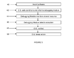
- Step 40 the software is installed onto the microcontroller.
- the operating system is configured to set the parameters that define unauthorised activity to a given shared resource on the microcontroller and to communicate these parameters to the debugging module.
- the operating system may define a certain level of RAM usage that a given software element is to use.
- the operating system may define certain memory addresses, special function registers, as "off limits" to particular software elements on the microcontroller.
- Step 44 the debugging module monitors the shared resources (26, 28, 29).
- Step 46 the debugging module detects a write action that is unauthorised and in Step 48 informs the operating system via notification signal 36.
- Step 50 the operating system may take an appropriate action, e.g. stop the engine, revert to an earlier microcontroller state or raise a fault output signal.
- Figure 4 depicts a memory map for the RAM resource within the microcontroller 3. It can be seen that the third party software element 24 on the microcontroller has been allocated 16K of memory. The remaining available RAM is used by the operating system 20, the first software element 22 and the special function register 28.
- the debugging module 30 may monitor RAM usage by the second software element 24 and in the event that more than 16K of resources are used by the element it may notify the operating system (Step 48).
- the debugging module 30 may monitor special function registers 28 (e.g. peripheral control registers) and in particular may monitor whether any software elements are writing to the addressable memory regions of such registers.
- special function registers 28 e.g. peripheral control registers
- the debugging module may monitor RAM regions that are shared with or read to/by other microcontrollers. In the event that a software element writes to such an area it could have a serious impact upon the operation of the ECU and could force a shut down of the engine. The debugging module may therefore be conveniently used to monitor such areas in use to detect unauthorised write operations.
- a log of the activity may be taken. This has the advantage of providing a clear audit trail to a software developer to facilitate redesign/recoding of the software element that was responsible for the exception.
- the log may be stored within non-volatile memory on the ECU.
- the debugging module may be able to signal the operating system such that preventative action can be taken, e.g. to disable the software element or to override the intended write action.
- microcontroller input/output pins are allocated during normal use and that consequently there will be spare pins available with which to interrogate the debugging module, e.g. during a maintenance or diagnostic function.
- the debugging module is an on circuit device that is already present on the microcontroller. By using the debugging module it is possible to segment the memory of a microcontroller that doesn't natively support memory segmentation. It also advantageously avoids the need for a specialist memory management unit 38 to be located on the microcontroller.
Landscapes
- Engineering & Computer Science (AREA)
- Theoretical Computer Science (AREA)
- Physics & Mathematics (AREA)
- General Engineering & Computer Science (AREA)
- General Physics & Mathematics (AREA)
- Computer Hardware Design (AREA)
- Quality & Reliability (AREA)
- Automation & Control Theory (AREA)
- Debugging And Monitoring (AREA)
- Test And Diagnosis Of Digital Computers (AREA)
Abstract
A method of detecting use of a shared resource within an ECU microcontroller, the microcontroller comprising at least one software element, a shared resource and an on-circuit debugging module, the method comprising: monitoring the shared resource with the debugging module for pre-defined write operations from the at least one software element; detecting a pre-defined write operation to the shared resource from the at least one software element.
Description
- The present invention relates to a microcontroller protection method and apparatus. In particular the present invention relates to the integration of software onto microcontrollers found within vehicle engine control units (ECUs) and the detection and prevention of unauthorised actions by the integrated software.
-
Figure 1 shows the components found within atypical ECU 1. Referring to the figure it can be seen that theECU 1 comprises a microcontroller 3 (Note: although only one microcontroller is shown here the ECU may comprise multiple microcontrollers), an input/output interface 5 (I/O interface), a communication chip 7 (CAN protocol controller) and associatedbus driver module 9, apower conditioning module 11 and amemory module 13. - The I/
O interface 5 comprises inputs from, for example, engine sensors and other vehicle sensors and outputs to, for example, the vehicle's fuel injectors and driver displays. Thecommunication chip 7 implements the various communication standard that is used in the vehicle. In this example, a controller area networking chip (CAN) is shown. - The
power conditioning module 11 is arranged to adjust inputs or outputs before they are read by the microcontroller. - The
microcontroller 3 comprises an operating system which runs a number of software modules that may control various vehicle functions such as injection timing, fuel injection amounts as well as monitor the health of the vehicle (and check for faults). Some of these software modules may be proprietary to the ECU manufacturer or supplier whereas other software elements may be third party software (e.g. customer supplied control strategies or CAN (Controller Area Network) libraries). - During the design and validation phase of the development of the microcontroller all installed software will be verified as far as possible. However, it is noted that, especially for third party software that has been supplied in binary (object) format, normal verification approaches such as code reviews, unit test and static analysis are not always possible. Therefore, during normal operation of the ECU/microcontroller (i.e. use of the production unit within the vehicle) there exists the potential for the onboard software to cause errors or corrupt other software/algorithms or even other hardware elements as a result of undetected or unverified errors within the software code.
- It is therefore an object of the present invention to overcome or substantially mitigate the above mentioned problems.
- According to a first aspect of the invention there is provided a method of detecting use of a shared resource within an ECU microcontroller, the microcontroller comprising at least one software element, a shared resource and an on-circuit debugging module, the method comprising: monitoring the shared resource with the debugging module for pre-defined write operations from the at least one software element; detecting a pre-defined write operation to the shared resource from the at least one software element.
- The present invention utilises an on-circuit debugging module during pre-production integration of software into the microcontroller and also during the production phase to detect unauthorised software operations. Essentially, the debugging module is used to conceptually partition any critical areas of the microcontroller, e.g. any shared resources such as RAM or special function registers.
- Conveniently, the monitoring step may comprise monitoring the shared resource during a pre-production phase of the development lifecycle of the microcontroller. Further, the monitoring step may comprise monitoring the shared resource during a production or implementation phase of the development lifecycle of the microcontroller.
- The microcontroller may comprise an operating system and preferably the method may further comprise the step of instructing the debugging module of the pre-defined write operations to be monitored using the microcontroller's operating system. It is noted that where the debugging module is designed for use during a design and development phase of the lifecycle of the microcontroller, it may be subsequently re-tasked by the operating system to monitor the shared resource.
- Preferably, the method further comprises the step of notifying the operating system when a pre-determined write operation is detected. Further, the method may comprise performing a detection action following notification of a pre-determined write operation. The detection action may comprise one or more of: resetting the ECU; outputting a notification signal; reverting the microcontroller to an earlier state.
- Conveniently, the shared resource may be: a RAM resource on the microcontroller; a special function register resource on the microcontroller; an addressable memory space on the microcontroller.
- Preferably, the pre-defined write operation to be monitored is a write action from the at least one software element to the shared resource. Alternatively or additionally, the pre-defined write operation to be monitored may be an advance notification message from the at least one software element of the intention to write to the shared resource.
- According to a second aspect of the invention there is provided a microcontroller within an ECU comprising: at least one software element; an operating system; a shared resource and an on-circuit debugging module, wherein the debugging module is arranged to monitor the shared resource for pre-defined write operations from the at least one software element and, upon detection of the pre-defined write operation, is arranged to output a notification signal to the operating system.
- It is noted that the second aspect of the present invention may comprise the preferred features of the first aspect of the present invention.
- The invention will now be described by way of example only with reference to the accompanying drawings, in which:
-
Figure 1 (described above) shows a representation of a typical engine control unit; -
Figure 2 shows a representation of the component parts of a microcontroller; -
Figure 3 is a memory map of the RAM module within the microcontroller ofFigure 2 ; -
Figure 4 is a flow chart showing a method of detecting unauthorised use of a shared resource in accordance with an embodiment of the present invention. - Turning to
Figure 2 , amicrocontroller 3 in accordance with an embodiment of the present invention is shown. The microcontroller in question is the strategy software microcontroller within theECU 1. It will however be appreciated that the invention as described below may be applied to any microcontroller within the ECU. - The
microcontroller 3 comprises a basic operating system (represented by element 20), two software elements (22 and 24) where thefirst software element 22 represents software proprietary to the ECU manufacturer/supplier and thesecond software element 24 represents software supplied by a third party. - The microcontroller also comprises a
RAM memory module 26 and a specialfunction register module 28, both of which are shared resources and accessible by bothsoftware elements resource 29, e.g. a RAM region that is shared with other microcontrollers, is also shown inFigure 2 . - An on
circuit debugging module 30 is also present within themicrocontroller 3. Such modules (e.g. the Motorola ® produced background debugging monitor) provide an in-circuit debugging functionality and are used during the development phase of the microcontroller by developers to ensure that application programs (such assoftware 22, 24) are properly integrated into the microcontroller environment. At the end of the development phase of the microcontroller such debugging modules are traditionally "switched off" and take no further part in the operation of the microcontroller. - Input and
output pins 32 connect the microcontroller to the rest of the ECU and other ECU components such as theconditioning module 11 andcommunication chip 7. It is noted that thedebugging module 30 also comprises input and output connections which are used during the development phase but which are then depopulated (capped off) for the production phase. - As discussed above if the verification of the
software elements - The present invention resides in the use of the
debugging module 30 during pre-production integration of software into the microcontroller and also during the production phase to detect unauthorised software operations. Essentially, the debugging module and operating system of the microcontroller are used to conceptually partition any critical areas of the microcontroller, e.g. any shared resources such as RAM (partition 34) or special function registers. In an embodiment of the present invention therefore thedebugging module 30 is used to detect write operations from software (and to notify theoperating system 20 which can then take appropriate action). - The flow chart of
Figure 3 depicts a method of detecting unauthorised activity in accordance with an embodiment of the present invention. InStep 40 the software is installed onto the microcontroller. - In
Step 42 the operating system is configured to set the parameters that define unauthorised activity to a given shared resource on the microcontroller and to communicate these parameters to the debugging module. For example, the operating system may define a certain level of RAM usage that a given software element is to use. Alternatively, the operating system may define certain memory addresses, special function registers, as "off limits" to particular software elements on the microcontroller. - In
Step 44 the debugging module monitors the shared resources (26, 28, 29). - In
Step 46 the debugging module detects a write action that is unauthorised and inStep 48 informs the operating system vianotification signal 36. - In
Step 50 the operating system may take an appropriate action, e.g. stop the engine, revert to an earlier microcontroller state or raise a fault output signal. -
Figure 4 depicts a memory map for the RAM resource within themicrocontroller 3. It can be seen that the thirdparty software element 24 on the microcontroller has been allocated 16K of memory. The remaining available RAM is used by theoperating system 20, thefirst software element 22 and thespecial function register 28. - In this example, the
debugging module 30 may monitor RAM usage by thesecond software element 24 and in the event that more than 16K of resources are used by the element it may notify the operating system (Step 48). - In alternative embodiments the
debugging module 30 may monitor special function registers 28 (e.g. peripheral control registers) and in particular may monitor whether any software elements are writing to the addressable memory regions of such registers. - In a yet further embodiment the debugging module may monitor RAM regions that are shared with or read to/by other microcontrollers. In the event that a software element writes to such an area it could have a serious impact upon the operation of the ECU and could force a shut down of the engine. The debugging module may therefore be conveniently used to monitor such areas in use to detect unauthorised write operations.
- When the debugging module notifies the operating system of an exception a log of the activity may be taken. This has the advantage of providing a clear audit trail to a software developer to facilitate redesign/recoding of the software element that was responsible for the exception. The log may be stored within non-volatile memory on the ECU.
- It is noted that some software elements will signal an intention to write to a given memory region before the write action actually takes place. In such circumstances the debugging module may be able to signal the operating system such that preventative action can be taken, e.g. to disable the software element or to override the intended write action.
- It is noted that not all of the microcontroller input/output pins are allocated during normal use and that consequently there will be spare pins available with which to interrogate the debugging module, e.g. during a maintenance or diagnostic function.
- As noted above the debugging module is an on circuit device that is already present on the microcontroller. By using the debugging module it is possible to segment the memory of a microcontroller that doesn't natively support memory segmentation. It also advantageously avoids the need for a specialist
memory management unit 38 to be located on the microcontroller. - It will be understood that the embodiments described above are given by way of example only and are not intended to limit the invention, the scope of which is defined in the appended claims. It will also be understood that the embodiments described may be used individually or in combination.
Claims (14)
- A method of detecting use of a shared resource within an ECU microcontroller (3), the microcontroller comprising at least one software element (22, 24), a shared resource (26, 28, 29) and an on-circuit debugging module (30), the method comprising:monitoring (44) the shared resource with the debugging module for pre-defined write operations from the at least one software element;detecting (46) a pre-defined write operation to the shared resource from the at least one software element.
- A method as claimed in Claim 1, wherein the monitoring step comprises monitoring the shared resource during a pre-production phase of the development lifecycle of the microcontroller.
- A method as claimed in Claim 1 or Claim 2, wherein the monitoring step comprises monitoring the shared resource during a production or implementation phase of the development lifecycle of the microcontroller.
- A method as claimed in any preceding claim, wherein the microcontroller comprises an operating system (20) and the method further comprises the step of instructing the debugging module of the pre-defined write operations to be monitored using the microcontroller's operating system.
- A method as claimed in Claim 4, wherein the debugging module is designed for use during a design and development phase of the lifecycle of the microcontroller and is subsequently re-tasked by the operating system to monitor the shared resource.
- A method as claimed in any preceding claim, further comprising the step of notifying (48) the operating system when a pre-determined write operation is detected.
- A method as claimed in Claim 6, further comprising performing a detection action (50) following notification of a pre-determined write operation.
- A method as claimed in Claim 7 wherein the detection action comprises one or more of: resetting the ECU; outputting a notification signal; reverting the microcontroller to an earlier state.
- A method as claimed in any preceding claim, wherein the shared resource is a RAM resource (26) on the microcontroller.
- A method as claimed in any preceding claim, wherein the shared resource is a special function register resource (28) on the microcontroller.
- A method as claimed in any preceding claim, wherein the shared resource is an addressable memory space on the microcontroller.
- A method as claimed in any preceding claim, wherein the pre-defined write operation to be monitored is a write action from the at least one software element to the shared resource.
- A method as claimed in any preceding claim, wherein the pre-defined write operation to be monitored is an advance notification message from the at least one software element of the intention to write to the shared resource.
- A microcontroller within an ECU comprising:at least one software element (22, 24);an operating system (20);a shared resource (26, 28) andan on-circuit debugging module (30),wherein the debugging module is arranged to monitor the shared resource for pre-defined write operations from the at least one software element and, upon detection of the pre-defined write operation, is arranged to output a notification signal to the operating system.
Priority Applications (1)
| Application Number | Priority Date | Filing Date | Title |
|---|---|---|---|
| EP09163593A EP2273329A1 (en) | 2009-06-24 | 2009-06-24 | Microcontroller protection method and apparatus comprising an on-circuit debugging module |
Applications Claiming Priority (1)
| Application Number | Priority Date | Filing Date | Title |
|---|---|---|---|
| EP09163593A EP2273329A1 (en) | 2009-06-24 | 2009-06-24 | Microcontroller protection method and apparatus comprising an on-circuit debugging module |
Publications (1)
| Publication Number | Publication Date |
|---|---|
| EP2273329A1 true EP2273329A1 (en) | 2011-01-12 |
Family
ID=41136633
Family Applications (1)
| Application Number | Title | Priority Date | Filing Date |
|---|---|---|---|
| EP09163593A Withdrawn EP2273329A1 (en) | 2009-06-24 | 2009-06-24 | Microcontroller protection method and apparatus comprising an on-circuit debugging module |
Country Status (1)
| Country | Link |
|---|---|
| EP (1) | EP2273329A1 (en) |
Cited By (2)
| Publication number | Priority date | Publication date | Assignee | Title |
|---|---|---|---|---|
| CN104657273A (en) * | 2015-03-05 | 2015-05-27 | 浪潮电子信息产业股份有限公司 | A Test Method for Software Occupying System Resources |
| EP3276493A1 (en) * | 2016-07-29 | 2018-01-31 | Wipro Limited | Method and system for debugging automotive applications in an electronic control unit of an automobile |
Citations (2)
| Publication number | Priority date | Publication date | Assignee | Title |
|---|---|---|---|---|
| EP1369787A2 (en) * | 2002-06-07 | 2003-12-10 | Matsushita Electric Industrial Co., Ltd. | Processor device and information processing device, compiling device, and compiling method using said processor device |
| US6769076B1 (en) * | 2000-02-07 | 2004-07-27 | Freescale Semiconductor, Inc. | Real-time processor debug system |
-
2009
- 2009-06-24 EP EP09163593A patent/EP2273329A1/en not_active Withdrawn
Patent Citations (2)
| Publication number | Priority date | Publication date | Assignee | Title |
|---|---|---|---|---|
| US6769076B1 (en) * | 2000-02-07 | 2004-07-27 | Freescale Semiconductor, Inc. | Real-time processor debug system |
| EP1369787A2 (en) * | 2002-06-07 | 2003-12-10 | Matsushita Electric Industrial Co., Ltd. | Processor device and information processing device, compiling device, and compiling method using said processor device |
Non-Patent Citations (5)
| Title |
|---|
| "Designing Software-Intensive Systems: Methods and Principles", April 2008, DR. PIERRE F. TIAKO, Langston University, article DANIEL G. WADDINGTON, NILABJA ROY, AND DOUGLAS C. SCHMIDT: "Dynamic Analysis and Profiling of Multi-threaded Systems", pages: 1 - 31, XP002550176 * |
| "MPC5533 MicrocontrollerProduct Brief", September 2007 (2007-09-01), pages 1 - 23, XP002550178, Retrieved from the Internet <URL:http://www.freescale.com/files/32bit/doc/prod_brief/MPC5533PB.pdf?WT_TYPE=Product%20Briefs&WT_VENDOR=FREESCALE&WT_FILE_FORMAT=pdf&WT_ASSET=Documentation> [retrieved on 20091013] * |
| DOUGLAS C. SCHMIDT, 13 October 2009 (2009-10-13), pages 1 - 7, XP002550177, Retrieved from the Internet <URL:http://www.cs.wustl.edu/~schmidt/resume.html> [retrieved on 20091013] * |
| O'KEEFFE H ET AL: "EINHEITLICHE DEBUG-SCHNITTSTELLE DER ZUKUNFT DER NEXUS-STANDARD SOLL DIE KOMMUNIKATION ZWISCHEN EMULATOR UND PROZESSOR VEREINHEITLICHEN", ELEKTRONIK, WEKA FACHZEITSCHRIFTENVERLAG, POING, DE, vol. 49, no. 18, 5 September 2000 (2000-09-05), pages 124 - 128, XP001107530, ISSN: 0013-5658 * |
| PIERRE-XAVIER THOMAS,: "Integrating Power Architecture e200 Core IP in SoCs", POWER ARCHITECTURE DEVELOPER CONFERENCE 07, 2007, pages 1 - 33, XP002550179, Retrieved from the Internet <URL:http://www.power.org/devcon/07/Session_Downloads/PADC07_Thomas_Integrating_Power_e200Cores_FINAL_02.pdf> [retrieved on 20091013] * |
Cited By (2)
| Publication number | Priority date | Publication date | Assignee | Title |
|---|---|---|---|---|
| CN104657273A (en) * | 2015-03-05 | 2015-05-27 | 浪潮电子信息产业股份有限公司 | A Test Method for Software Occupying System Resources |
| EP3276493A1 (en) * | 2016-07-29 | 2018-01-31 | Wipro Limited | Method and system for debugging automotive applications in an electronic control unit of an automobile |
Similar Documents
| Publication | Publication Date | Title |
|---|---|---|
| US8543286B2 (en) | Vehicle hardware integrity analysis systems and methods | |
| US9058419B2 (en) | System and method for verifying the integrity of a safety-critical vehicle control system | |
| US6421790B1 (en) | Method and circuit for analysis of the operation of a microcontroller using signature analysis of data and instructions | |
| US20200290533A1 (en) | Method And System For Secure Signal Manipulation For Testing Integrated Safety Functionalities | |
| US20170249224A1 (en) | Semiconductor device | |
| EP2113087B1 (en) | System and computer program product for testing a logic circuit | |
| Himmler et al. | Hardware-in-the-Loop Testing in the Context of ISO 26262 | |
| JP5680514B2 (en) | Computer having self-diagnosis function, software creation method, and software creation device | |
| Bellotti et al. | How future automotive functional safety requirements will impact microprocessors design | |
| EP2273329A1 (en) | Microcontroller protection method and apparatus comprising an on-circuit debugging module | |
| CN106383507B (en) | Fault management method for vehicle engine control system | |
| US9903300B2 (en) | Method for shutting down an electrically controlled component of a vehicle in a case of error of a processing unit controlling the component | |
| US9678870B2 (en) | Diagnostic apparatus, control unit, integrated circuit, vehicle and method of recording diagnostic data | |
| US9384078B2 (en) | Method for diagnosing a mechanism of untimely cut-offs of the power supply to a motor vehicle computer | |
| Pintard et al. | Using fault injection to verify an autosar application according to the ISO 26262 | |
| US9286244B2 (en) | Method and device for monitoring an unauthorized memory access of a computing device, in particular in a motor vehicle | |
| CN102591322A (en) | Checking of functions of a control system having components | |
| CN107210937A (en) | Bus monitor in data/address bus | |
| JP7504222B2 (en) | In-vehicle control systems | |
| CN104008049A (en) | Method for monitoring stack storage in motor vehicle controller work system | |
| Panaroni et al. | Safety in automotive software: An overview of current practices | |
| Brewerton et al. | Practical use of autosar in safety critical automotive systems | |
| Pandey et al. | A Proposed Systematic Software Robustness Verification Framework (SRVF) for Enhancing Critical Software Module Robustness | |
| KR101856065B1 (en) | Apparatus and method for testing on board diagnosis | |
| Gandhi et al. | Techniques and measures for improving domain controller availability while maintaining functional safety in mixed criticality automotive safety systems |
Legal Events
| Date | Code | Title | Description |
|---|---|---|---|
| PUAI | Public reference made under article 153(3) epc to a published international application that has entered the european phase |
Free format text: ORIGINAL CODE: 0009012 |
|
| AK | Designated contracting states |
Kind code of ref document: A1 Designated state(s): AT BE BG CH CY CZ DE DK EE ES FI FR GB GR HR HU IE IS IT LI LT LU LV MC MK MT NL NO PL PT RO SE SI SK TR |
|
| AX | Request for extension of the european patent |
Extension state: AL BA RS |
|
| 17P | Request for examination filed |
Effective date: 20110712 |
|
| 17Q | First examination report despatched |
Effective date: 20110908 |
|
| STAA | Information on the status of an ep patent application or granted ep patent |
Free format text: STATUS: THE APPLICATION IS DEEMED TO BE WITHDRAWN |
|
| 18D | Application deemed to be withdrawn |
Effective date: 20130611 |