EP2273236B1 - Verfahren und Systeme zur routenbasierten Blättern einer Navigationskarte - Google Patents
Verfahren und Systeme zur routenbasierten Blättern einer Navigationskarte Download PDFInfo
- Publication number
- EP2273236B1 EP2273236B1 EP10167593.2A EP10167593A EP2273236B1 EP 2273236 B1 EP2273236 B1 EP 2273236B1 EP 10167593 A EP10167593 A EP 10167593A EP 2273236 B1 EP2273236 B1 EP 2273236B1
- Authority
- EP
- European Patent Office
- Prior art keywords
- flight plan
- reference point
- aircraft
- navigational
- graphical
- Prior art date
- Legal status (The legal status is an assumption and is not a legal conclusion. Google has not performed a legal analysis and makes no representation as to the accuracy of the status listed.)
- Active
Links
Images


Classifications
-
- G—PHYSICS
- G01—MEASURING; TESTING
- G01C—MEASURING DISTANCES, LEVELS OR BEARINGS; SURVEYING; NAVIGATION; GYROSCOPIC INSTRUMENTS; PHOTOGRAMMETRY OR VIDEOGRAMMETRY
- G01C23/00—Combined instruments indicating more than one navigational value, e.g. for aircraft; Combined measuring devices for measuring two or more variables of movement, e.g. distance, speed or acceleration
-
- G—PHYSICS
- G01—MEASURING; TESTING
- G01C—MEASURING DISTANCES, LEVELS OR BEARINGS; SURVEYING; NAVIGATION; GYROSCOPIC INSTRUMENTS; PHOTOGRAMMETRY OR VIDEOGRAMMETRY
- G01C21/00—Navigation; Navigational instruments not provided for in groups G01C1/00 - G01C19/00
- G01C21/20—Instruments for performing navigational calculations
-
- G—PHYSICS
- G01—MEASURING; TESTING
- G01C—MEASURING DISTANCES, LEVELS OR BEARINGS; SURVEYING; NAVIGATION; GYROSCOPIC INSTRUMENTS; PHOTOGRAMMETRY OR VIDEOGRAMMETRY
- G01C21/00—Navigation; Navigational instruments not provided for in groups G01C1/00 - G01C19/00
- G01C21/26—Navigation; Navigational instruments not provided for in groups G01C1/00 - G01C19/00 specially adapted for navigation in a road network
-
- G—PHYSICS
- G08—SIGNALLING
- G08G—TRAFFIC CONTROL SYSTEMS
- G08G1/00—Traffic control systems for road vehicles
- G08G1/20—Monitoring the location of vehicles belonging to a group, e.g. fleet of vehicles, countable or determined number of vehicles
-
- B—PERFORMING OPERATIONS; TRANSPORTING
- B60—VEHICLES IN GENERAL
- B60R—VEHICLES, VEHICLE FITTINGS, OR VEHICLE PARTS, NOT OTHERWISE PROVIDED FOR
- B60R25/00—Fittings or systems for preventing or indicating unauthorised use or theft of vehicles
- B60R25/30—Detection related to theft or to other events relevant to anti-theft systems
- B60R25/33—Detection related to theft or to other events relevant to anti-theft systems of global position, e.g. by providing GPS coordinates
-
- G—PHYSICS
- G01—MEASURING; TESTING
- G01S—RADIO DIRECTION-FINDING; RADIO NAVIGATION; DETERMINING DISTANCE OR VELOCITY BY USE OF RADIO WAVES; LOCATING OR PRESENCE-DETECTING BY USE OF THE REFLECTION OR RERADIATION OF RADIO WAVES; ANALOGOUS ARRANGEMENTS USING OTHER WAVES
- G01S19/00—Satellite radio beacon positioning systems; Determining position, velocity or attitude using signals transmitted by such systems
- G01S19/01—Satellite radio beacon positioning systems transmitting time-stamped messages, e.g. GPS [Global Positioning System], GLONASS [Global Orbiting Navigation Satellite System] or GALILEO
- G01S19/13—Receivers
- G01S19/35—Constructional details or hardware or software details of the signal processing chain
-
- G—PHYSICS
- G08—SIGNALLING
- G08G—TRAFFIC CONTROL SYSTEMS
- G08G5/00—Traffic control systems for aircraft, e.g. air-traffic control [ATC]
- G08G5/0017—Arrangements for implementing traffic-related aircraft activities, e.g. arrangements for generating, displaying, acquiring or managing traffic information
- G08G5/0021—Arrangements for implementing traffic-related aircraft activities, e.g. arrangements for generating, displaying, acquiring or managing traffic information located in the aircraft
-
- G—PHYSICS
- G08—SIGNALLING
- G08G—TRAFFIC CONTROL SYSTEMS
- G08G5/00—Traffic control systems for aircraft, e.g. air-traffic control [ATC]
- G08G5/0047—Navigation or guidance aids for a single aircraft
- G08G5/0052—Navigation or guidance aids for a single aircraft for cruising
-
- G—PHYSICS
- G08—SIGNALLING
- G08G—TRAFFIC CONTROL SYSTEMS
- G08G5/00—Traffic control systems for aircraft, e.g. air-traffic control [ATC]
- G08G5/0073—Surveillance aids
- G08G5/0086—Surveillance aids for monitoring terrain
Definitions
- the subject matter described herein relates generally to avionics systems, and more particularly, embodiments of the subject matter relate to avionics systems and related cockpit displays adapted for scrolling a navigational map based on a flight plan.
- Modem electronic displays for vehicles display a considerable amount of information, such as vehicle position, navigation and terrain information.
- many modem flight deck displays include a lateral view, generally known as a lateral map display, which is basically a top-down view of the flight plan that may include, for example, a top-down view aircraft symbol, terrain information, political boundaries, navigation aids and/or waypoint symbols, line segments that interconnect the waypoint symbols, and range rings.
- a lateral map display which is basically a top-down view of the flight plan that may include, for example, a top-down view aircraft symbol, terrain information, political boundaries, navigation aids and/or waypoint symbols, line segments that interconnect the waypoint symbols, and range rings.
- a user may manually adjust the area displayed in the lateral map display by scrolling the map in either a lateral direction (e.g., up or down, left or right) or a cardinal direction (e.g., North or South, East or West), or by manually dragging the map to a desired area.
- a lateral direction e.g., up or down, left or right
- a cardinal direction e.g., North or South, East or West
- adjusting the area displayed in the lateral map in the proper direction can be difficult and/or nonintuitive, for example, when the lateral map is oriented in the direction of travel (e.g., heading up) or when the flight plan turns in a direction that is not evident by the current state of the lateral map display.
- repositioning the lateral map display may undesirably increase the workload on the pilot and/or co-pilot.
- JP2008249463 discloses a system for displaying map information, in which a navigation device in a vehicle detects the position of a vehicle, and calculates a guide route. The device displays simultaneously a route selected from the list information calculated from the position and map information on its periphery.
- JP2003177028 discloses a system to provide an electronic map display.
- a route is displayed in a scroll bar in the upper part of a display screen, including a departure place and a destination.
- a slider is movable by a user, and names of intersections near a slider position are displayed at the slider position.
- a map drawn with the slider position at the center is displayed.
- US2006005147A1 discloses systems and methods for displaying a map onboard an aircraft.
- a map of an area at least proximate to an aircraft at an aircraft flight deck during flight is displayed, with the map presenting a feature having a first position relative to a boundary of the map.
- At least one operator-selectable input element may be displayed at least proximate to the display of the map and accessible to an operator of the aircraft.
- An operator-based request can be received to change a position of the feature on the map relative to the boundary, and, in response to the request, updating the display of the map by shifting all points of the map so that the feature has a second position relative to the boundary, with the second position being different than the first position.
- the present invention provides a method according to claim 1 of the appended claims.
- the invention further provides a display system according to claim 7 of the appended claims.
- Coupled means that one element/node/feature is directly or indirectly joined to (or directly or indirectly communicates with) another element/node/feature, and not necessarily mechanically.
- drawings may depict one exemplary arrangement of elements, additional intervening elements, devices, features, or components may be present in an embodiment of the depicted subject matter.
- certain terminology may also be used in the following description for the purpose of reference only, and thus are not intended to be limiting.
- a graphical adjustment element that allows a user to adjust (or scroll) a navigational map along the track (or path) defined by a flight plan (or travel route).
- a user can quickly and intuitively reposition the navigational map to view and analyze content and/or information for a portion of the flight plan (e.g., upcoming neighboring air traffic, weather conditions, and the like) and ascertain the relative real-world positioning of the aircraft with respect to the flight plan.
- the overall workload on the user is reduced and the graphical adjustment element is implemented in a manner that does not degrade situational awareness and enables a user to dedicate efforts to more significant tasks, such as, for example, operating the aircraft, coordinating and/or communicating with air traffic control, and the like.
- a predefined route for travel e.g., a travel plan or travel route
- another vehicle e.g., automobiles, marine vessels, trains
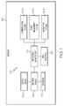
- FIG. 1 depicts an exemplary embodiment of a display system 100, which may be located onboard a vehicle such as an aircraft 118.
- the display system 100 includes, without limitation, a display device 102, a navigation system 104, a communications system 106, a flight management system 108 (FMS), a processing architecture 112, and a graphics module 114.
- the display system 100 may further include a user interface 110 for enabling interactivity with the display system 100 and a database 116 suitably configured to support operation of the display system 100, as described in greater detail below.
- FIG. 1 is a simplified representation of a display system 100 for purposes of explanation and ease of description, and FIG. 1 is not intended to limit the application or scope of the subject matter in any way.
- the display system 100 and/or aircraft 118 will include numerous other devices and components for providing additional functions and features, as will be appreciated in the art.
- the display system 100 and/or aircraft 118 may include one or more avionics systems (e.g., a weather system, an air traffic management system, a radar system, a traffic avoidance system) coupled to the flight management system 108 and/or the processing architecture 112 for obtaining and/or providing real-time flight-related information that may be displayed on the display device 102.
- avionics systems e.g., a weather system, an air traffic management system, a radar system, a traffic avoidance system
- the display device 102 is coupled to the graphics module 114.
- the graphics module 114 is coupled to the processing architecture 112, and the processing architecture 112 and the graphics module 114 are cooperatively configured to display, render, or otherwise convey one or more graphical representations or images associated with operation of the aircraft 118 on the display device 102, as described in greater detail below.
- the processing architecture 112 is coupled to the navigation system 104 for obtaining real-time navigational data and/or information regarding operation of the aircraft 118 to support operation of the display system 100.
- the communications system 106 is coupled to the processing architecture 112 and configured to support communications to and/or from the aircraft 118, as will be appreciated in the art.
- the processing architecture 112 is also coupled to the flight management system 108, which in turn, may also be coupled to the navigation system 104 and the communications system 106 for providing real-time data and/or information regarding operation of the aircraft 118 to the processing architecture 112 to support operation of the aircraft 118, as will be appreciated in the art.
- the user interface 110 is coupled to the processing architecture 112, and the user interface 110 and the processing architecture 112 are cooperatively configured to allow a user to interact with the display device 102 and other elements of display system 100, as described in greater detail below.
- the display device 102 is realized as an electronic display configured to graphically display flight information or other data associated with operation of the aircraft 118 under control of the graphics module 114.
- the display device 102 is located within a cockpit of the aircraft 118. It will be appreciated that although FIG. 1 shows a single display device 102, in practice, additional display devices may be present onboard the aircraft 118.
- the user interface 110 is also located within the cockpit of the aircraft 118 and adapted to allow a user (e.g., pilot, co-pilot, or crew member) to interact with the display system 100 and enables a user to indicate, select, or otherwise manipulate content displayed on the display device 102, as described in greater detail below.
- the user interface 110 may be realized as a keypad, touchpad, keyboard, mouse, touchscreen, joystick, knob, microphone, or another suitable device adapted to receive input from a user. It should be appreciated that although FIG. 1 shows the display device 102 and the user interface 110 as being located within the aircraft 118, in practice, the display device 102 and/or user interface 110 may be located outside the aircraft 118 (e.g., on the ground as part of an air traffic control center or another command center) and communicatively coupled to the remaining elements of the display system 100 (e.g., via a data link).
- the navigation system 104 is configured to obtain one or more navigational parameters associated with operation of the aircraft 118.
- the navigation system 104 may be realized as a global positioning system (GPS), inertial reference system (IRS), or a radio-based navigation system (e.g., VHF omni-directional radio range (VOR) or long range aid to navigation (LORAN)), and may include one or more navigational radios or other sensors suitably configured to support operation of the navigation system 104, as will be appreciated in the art.
- GPS global positioning system
- IRS inertial reference system
- LORAN long range aid to navigation
- the navigation system 104 is capable of obtaining and/or determining the instantaneous position of the aircraft 118, that is, the current location of the aircraft 118 (e.g., the latitude and longitude) and the altitude or above ground level for the aircraft 118. In some embodiments, the navigation system 104 may also obtain and/or determine the heading of the aircraft 118 (i.e., the direction the aircraft is traveling in relative to some reference).
- the communications system 106 is suitably configured to support communications between the aircraft 118 and another aircraft or ground location (e.g., air traffic control). In this regard, the communications system 106 may be realized using a radio communication system or another suitable data link system.
- the flight management system 108 (or, alternatively, a flight management computer) is located onboard the aircraft 118.
- FIG. 1 is a simplified representation of display system 100, in practice, the flight management system 108 may be coupled to one or more additional modules or components as necessary to support navigation, flight planning, and other aircraft control functions in a conventional manner.
- the flight management system 108 maintains information pertaining to a current flight plan (or alternatively, a current route or travel plan).
- the current flight plan may comprise either a selected or otherwise designated flight plan for subsequent execution, a flight plan selected for review on the display device 102, and/or a flight plan currently being executed by the aircraft 118.
- a flight plan should be understood as a sequence of navigational reference points that define a flight path or route for the aircraft 118.
- the navigational reference points may comprise navigational aids, such as VHF omni-directional ranges (VORs), distance measuring equipment (DMEs), tactical air navigation aids (TACANs), and combinations thereof (e.g., VORTACs), landing and/or departure locations (e.g., airports, airstrips, runways, landing strips, heliports, helipads, and the like), points of interest or other features on the ground, as well as position fixes (e.g., initial approach fixes (IAFs) and/or final approach fixes (FAFs)) and other navigational reference points used in area navigation (RNAV).
- VORs VHF omni-directional ranges
- DMEs distance measuring equipment
- TACANs tactical air navigation aids
- VORTACs e.g., VORTACs
- landing and/or departure locations e.g., airports, airstrips, runways, landing strips, heliports, helipads, and the like
- IAFs initial approach fixes
- a flight plan may include an initial or beginning reference point (e.g., a departure or takeoff location), a final navigational reference point (e.g., an arrival or landing location), and one or more intermediate navigational reference points (e.g., waypoints, positional fixes, and the like) that define the desired path or route for the aircraft 118 from the initial navigational reference point to the final navigational reference point.
- the intermediate navigational reference points may define one or more airways for the aircraft 118 en route to the final navigational reference point.
- the along track distance (or length) of the flight plan comprises the sum of all of the straight line ground distances between adjacent navigational reference points of the flight plan, that is, the total ground distance corresponding to the route defined by the plurality of navigational reference points comprising the flight plan.
- the along track distance (or length) of the flight plan is equal to the sum of the straight line ground distance between a location corresponding to the first navigational reference point and a location corresponding to the second navigational reference point and the straight line ground distance between the location corresponding to the second navigational reference point and a location corresponding to the third navigational reference point.
- along track distance should be understood as referring to the distance between two points as measured along the route or path defined by the navigational reference points comprising the flight plan.
- the flight management system 108 may include a database that maintains a plurality of predefined flight plans, wherein a predefined flight plan from the database may be selected by a user via user interface 110 for use as the current flight plan.
- the current flight plan may be uplinked via the communications system 106.
- the user may utilize the user interface 110 to manually enter or indicate the desired endpoints (e.g., the initial and final navigational reference points) for the current flight plan.
- the user may manually enter the intermediate navigational reference points (e.g., via user interface 110), or alternatively, the intermediate navigational reference points may be automatically generated by the flight management system 108 based on the endpoints (e.g., the initial and final navigational reference points) of the flight plan, as will be appreciated in the art.
- the intermediate navigational reference points may be automatically generated by the flight management system 108 based on the endpoints (e.g., the initial and final navigational reference points) of the flight plan, as will be appreciated in the art.
- the processing architecture 112 and/or graphics module 114 are configured to display and/or render information pertaining to the currently selected flight plan on the display device 102 to allow a user (e.g., via user interface 110) to review various aspects (e.g., estimated fuel requirements, estimated flight time, rates of ascent/descent, flight levels and/or altitudes, and the like) of the currently selected flight plan.
- various aspects e.g., estimated fuel requirements, estimated flight time, rates of ascent/descent, flight levels and/or altitudes, and the like
- the processing architecture 112 generally represents the hardware, software, and/or firmware components configured to facilitate the display and/or rendering of a navigational map on the display device 102 and perform additional tasks and/or functions described in greater detail below.
- the processing architecture 112 may be implemented or realized with a general purpose processor, a content addressable memory, a digital signal processor, an application specific integrated circuit, a field programmable gate array, any suitable programmable logic device, discrete gate or transistor logic, discrete hardware components, or any combination thereof, designed to perform the functions described herein.
- the processing architecture 112 may also be implemented as a combination of computing devices, e.g., a combination of a digital signal processor and a microprocessor, a plurality of microprocessors, one or more microprocessors in conjunction with a digital signal processor core, or any other such configuration.
- the processing architecture 112 includes processing logic that may be configured to carry out the functions, techniques, and processing tasks associated with the operation of the display system 100, as described in greater detail below.
- the steps of a method or algorithm described in connection with the embodiments disclosed herein may be embodied directly in hardware, in firmware, in a software module executed by the processing architecture 112, or in any practical combination thereof.
- the graphics module 114 generally represents the hardware, software, and/or firmware components configured to control the display and/or rendering of a navigational map on the display device 102 and perform additional tasks and/or functions described in greater detail below.
- the graphics module 114 accesses one or more databases 116 suitably configured to support operations of the graphics module 114, as described below.
- the database 116 may comprise a terrain database, an obstacle database, a navigational database, a geopolitical database, a terminal airspace database, a special use airspace database, or other information for rendering and/or displaying content on the display device 102, as described below. It will be appreciated that although FIG. 1 shows a single database 116 for purposes of explanation and ease of description, in practice, numerous databases will likely be present in a practical embodiment of the display system 100.
- a display system 100 may be configured to perform a display process 200 and additional tasks, functions, and operations described below.
- the various tasks may be performed by software, hardware, firmware, or any combination thereof.
- the following description may refer to elements mentioned above in connection with FIG. 1 .
- the tasks, functions, and operations may be performed by different elements of the described system, such as the display device 102, the flight management system 108, the user interface 110, the processing architecture 112, the graphics module 114 and/or the database 116. It should be appreciated that any number of additional or alternative tasks may be included, and may be incorporated into a more comprehensive procedure or process having additional functionality not described in detail herein.
- a display process 200 may be performed to enable a user, such as a pilot or crew member, to quickly and easily adjust (or scroll) the displayed area (or field of view) of the navigational map along the flight path or route defined by a flight plan (or travel plan).
- the display process 200 initializes by displaying a navigational map pertaining to operation of a vehicle, such as an aircraft, in a viewing area on a display device associated with the vehicle (task 202). For example, referring now to FIG. 3 , and with continued reference to FIG. 1 and FIG.
- the display process 200 may display and/or render a navigational map 300 associated with the current (or instantaneous) location of an aircraft on a display device in the aircraft.
- the aircraft 302 and/or terrain 304 are positioned and/or rendered within the navigational map 300 with respect to the center location in a manner that accurately reflects the real-world positioning of the aircraft 302 and/or terrain 304 relative to the center location such that the navigational map 300 corresponds to a top-down view of the aircraft 118 (e.g., from a higher altitude than the aircraft 118 is currently flying).
- the graphics module 114 may be configured to control the rendering of the navigational map 300, which may be graphically displayed on the display device 102.
- the display process 200 may also be configured to render a graphical representation of the aircraft 302 on the map 300, which may be overlaid or rendered on top of a background 304.
- FIG. 3 depicts a top view (e.g., from above the aircraft 302) of the navigational map 300, in practice, alternative embodiments may utilize various perspective views, such as side views, three-dimensional views (e.g., a three-dimensional synthetic vision display), angular or skewed views, and the like.
- the background 304 comprises a graphical representation of the terrain, topology, airspace designations and/or restrictions, or other suitable items or points of interest corresponding to the currently displayed area of the navigational map 300, which may be maintained in a terrain database, a navigational database, a geopolitical database, or another suitable database.
- the display process 200 may render other real-time flight related information that is within the geographic area corresponding to the currently displayed area of the navigational map 300 or within a particular proximity of the aircraft, such as, for example, weather conditions, radar data, neighboring air traffic, and the like, as will be appreciated in the art.
- the display process 200 renders and/or displays a graphical representation of a portion of the flight plan 306 overlying the background 304 such that the portion of the flight plan 306 within the geographic area corresponding to the currently displayed area of the navigational map 300 is presented on the display device.
- the displayed area of the navigational map corresponds to the geographic area that is currently displayed in the navigational map 300, that is, the field of view about the center location of the navigational map 300.
- the center location of the navigational map 300 comprises a reference location for the middle or geometric center of the navigational map 300 which corresponds to a geographic location.
- the map 300 is associated with the movement of the aircraft, and the background 304 refreshes or updates as the aircraft travels, such that the graphical representation of the aircraft 302 is positioned over the terrain background 304 in a manner that accurately reflects the current (e.g., instantaneous or substantially real-time) real-world positioning of the aircraft 118 relative to the earth.
- the map 300 may be initially centered on the aircraft 302 such that the center location of the navigational map 300 corresponds to the current location of the aircraft 302.
- the center location of the navigational map 300 may be updated or refreshed such that it corresponds to the instantaneous location of the aircraft 302 as the aircraft travels, as will be appreciated in the art.
- the center location of the navigational map 300 may correspond to a geographic location that is independent of the current location of the aircraft.
- the navigational map 300 is displayed with initial display settings.
- the display settings comprise one or more characteristics that control the manner in which the aircraft 302 and/or terrain 304 initially appear on the display device, such as, for example, an initial orientation, center location, and range setting.
- the orientation of the navigational map 300 is north-up (i.e., moving upward on the map 300 corresponds to traveling northward).
- the orientation of the navigational map 300 may be track-up or heading-up (i.e., aligned such that the aircraft 302 is always traveling in an upward direction and the background 304 adjusted accordingly) or with another direction (e.g., east-up), and the subject matter described herein is not limited to any particular orientation of the navigational map 300.
- the center location of the navigational map 300 comprises a reference location for the middle or geometric center of the navigational map 300 which corresponds to a geographic location on the ground.
- the aircraft 302 and/or terrain 304 are positioned and/or rendered within the navigational map 300 with respect to the center location in a manner that accurately reflects the real-world positioning of the aircraft 302 and/or terrain 304 relative to the center location such that the navigational map 300 corresponds to a top-down view of the aircraft 118 (e.g., from a higher altitude than the aircraft 118 is currently flying).
- the range setting for the navigational map 300 corresponds to the field of view for the currently displayed area of the navigational map 300, that is, the amount of geographic area (e.g., terrain 304) displayed or otherwise represented in the navigational map 300.
- the range setting for the navigational map 300 is inversely related to the scale of the navigational map 300, that is, the ratio of a single unit of distance on the map 300 to a corresponding distance on the ground.
- a higher range setting corresponds to a lower scale (or a larger field of view) and a larger displayed area for the navigational map 300 while a lower range setting corresponds to a higher scale (or a smaller field of view) and a smaller displayed area for the navigational map 300.
- the display process 200 indicates the range setting for the navigational map 300 by displaying and/or rendering a range ring 308 on the navigational map 300.
- the range ring 308 comprises a circle that is always displayed with a fixed dimension and/or size on the navigational map 300 and indicates the range setting for the navigational map 300.
- the range setting is equal to the real-world distance that corresponds to (or is equivalent to) the radius of the range ring 308 based on the scale of the navigational map 300.
- the range ring 308 indicates that the radius of the circle comprising the range ring 308 corresponds to a distance of eleven nautical miles.
- the display process 200 continues by displaying a vertical profile on the display device (task 204).
- the display process 200 displays the vertical profile corresponding to a portion of the flight plan that is within currently displayed area of the navigational map.
- the display process 200 may display the vertical profile 310 corresponding to the portion of the flight plan 306 displayed within the currently displayed area of the navigational map 300.
- the display process 200 correlates the vertical profile with the portion of the flight plan within the currently displayed area, such that when the currently displayed area is adjusted to show a different portion of the flight plan, the display process 200 updates the vertical profile accordingly, as described in greater detail below.
- the display process 200 continues by displaying a graphical adjustment path (or track) on the display device the navigational map (task 206).
- the graphical adjustment path corresponds to or otherwise defines a track or path for a graphical adjustment element, as described in greater detail below.
- the graphical adjustment path is realized as a scrollbar path 312 that defines a track for a graphical adjustment element 318 as shown in FIG. 3 .
- the length (or another suitable dimension) of the graphical adjustment path corresponds to the total along track distance between two navigational reference points of the flight plan (or travel plan).
- the length of a flight plan scrollbar path corresponds to the along track distance from the initial navigational reference point to the final navigational reference point of the flight plan (or alternatively, the along track distance or length of the flight plan).
- the flight plan scrollbar path 312 may be rendered and/or displayed on the display device proximate to or overlying the navigational map 300.
- the flight plan scrollbar path 312 is oriented horizontally across the viewing area on the display device, and positioned proximate a border of the navigational map 300. For example, as shown in FIG.
- the flight plan scrollbar path 312 is oriented horizontally across the entire width of the viewing area of the display device that the navigational map 300 is displayed on, and the flight plan scrollbar path 312 is positioned proximate the lower edge of the navigational map 300.
- the display process 200 renders and/or displays a graphical representation of the aircraft 314 overlying the flight plan scrollbar path 312 and positioned with respect to the flight plan scrollbar path 312 such that the aircraft 314 position relative to the flight plan scrollbar path 312 corresponds to the along track distance from the initial navigational reference point of the flight plan to the current location of the aircraft 302.
- the display process 200 continues by determining whether a portion of the flight plan is displayed within the currently displayed area of the navigational map (task 208). In an exemplary embodiment, when a portion of the route defined by the flight plan is displayed within the currently displayed area, the display process 200 continues by displaying and/or rendering a graphical adjustment element, such as a slider or another suitable element, overlying the graphical adjustment path for enabling a user to adjust (or scroll) the displayed area of the navigational map along the route defined by the flight plan (task 210). In an exemplary embodiment, the graphical adjustment element is realized as a slider 318 overlying the flight plan scrollbar path 312, as shown in FIG. 3 . As described in greater detail below in the context of the slider display process 700 of FIG.
- the graphical adjustment element is rendered and/or displayed overlying the graphical adjustment path at a position that corresponds to the along track distance between the currently displayed area and the initial navigational reference point of the flight plan.
- the position of the graphical adjustment element with respect to the graphical adjustment path corresponds to the location of the currently displayed area relative to the initial navigational reference point of the flight plan.
- the slider 318 is positioned toward the end of the flight plan scrollbar path 312, indicating that the currently displayed area of the navigational map 300 is near the final navigational reference point (KRNO) of the flight plan.
- the slider 318 is positioned near the right edge of the flight plan scrollbar path 312 and the slider 318 overlaps an indicator 320 on the flight plan scrollbar path 312 that corresponds to the final navigational reference point (KRNO) of the flight plan, thereby indicating that the final navigational reference point 322 (KRNO) is within the currently displayed area of the navigational map 300, i.e., the final navigational reference point 322 is rendered and/or displayed on the navigational map 300.
- KRNO final navigational reference point
- the display process 200 correlates the graphical adjustment element and the displayed area of the navigational map (task 212).
- any change or adjustment to the displayed area of the navigational map 300 produces a corresponding change in the center position of the graphical adjustment element 318 with respect to the graphical adjustment path 312
- any change or adjustment of the center position of the graphical adjustment element 318 with respect to the graphical adjustment path 312 produces a corresponding change in the currently displayed area of the navigational map 300 and/or the vertical profile 310.
- a user may manipulate the user interface 110 to manipulate and/or slide the slider 318, select (or click on) a portion of the flight plan scrollbar path 312 unoccupied by the slider 318, or otherwise increment the slider 318 (e.g., by using graphical control elements such as arrow buttons 324) to adjust the slider position with respect to the flight plan scrollbar path 312.
- the center location of the currently displayed area of the navigational map 300 is updated and/or adjusted in a manner that corresponds to the change in the slider position such that the currently displayed area of the navigational map 300 reflects the updated slider position.
- the vertical profile is updated and/or adjusted to reflect a portion of the flight plan corresponding to the updated slider position, as described in greater detail below.
- the slider 318 and scrollbar path 312 collectively function as a scrollbar for scrolling or otherwise adjusting the displayed area of the navigational map along the route defined by the flight plan.
- the user may adjust the center location of the navigational map 300 (e.g., by moving and/or repositioning the center location of the currently displayed area in a cardinal direction using graphical control elements 326), and in response, the center position of the slider 318 is updated and/or adjusted such that the position of the slider 318 with respect to the flight plan scrollbar path 312 corresponds to the updated center location for the displayed area of the navigational map 300.
- the size and/or width of the slider 318 is adjusted and/or updated in a manner that reflects the field of view of the currently displayed area, as described in greater detail below.
- a display system 100 may be configured to perform a scrollbar display process 400 and additional tasks, functions, and operations described below.
- the various tasks may be performed by software, hardware, firmware, or any combination thereof.
- the following description may refer to elements mentioned above in connection with FIGS. 1-3 .
- the tasks, functions, and operations may be performed by different elements of the described system, such as the display device 102, the flight management system 108, the user interface 110, the processing architecture 112, the graphics module 114 and/or the database 116. It should be appreciated that any number of additional or alternative tasks may be included, and may be incorporated into a more comprehensive procedure or process having additional functionality not described in detail herein.
- a scrollbar display process 400 initializes by displaying and/or rendering the graphical adjustment path in an allocated region within the viewing area of the display device (task 402). For example, in the exemplary embodiment shown in FIG. 3 , when the scrollbar path 312 is oriented horizontally, the scrollbar path 312 is allocated a region adjacent to a border (or edge) of the navigational map 300 (e.g., adjacent to the bottom and/or top of the navigational map 300) having a horizontal dimension that corresponds to the width of the viewing area of the display device. In an exemplary embodiment, the scrollbar display process 400 continues by determining the distance (or length) of the flight plan (task 404).
- the scrollbar display process 400 determines and/or calculates the total along track distance from the initial navigational reference point to the final navigational reference point of the flight plan, that is, the straight line ground distance when sequentially traversing the ground locations that correspond to the individual navigational reference points of the route defined by the flight plan.
- the scrollbar display process 400 continues by calculating or otherwise determining the scale of the graphical adjustment path (task 406).
- the scale of the graphical adjustment path corresponds to the relationship of the length of the graphical adjustment path on the display device to the along track distance (or length) of the flight plan.
- the scale is equal to the length of the scrollbar path in pixels (e.g., the number of pixels horizontally occupied by the flight plan scrollbar path) to the distance (or length) of the flight plan (e.g., the total along track distance for the flight plan). For example, if the flight plan scrollbar path is two hundred pixels long and the flight plan distance is four hundred nautical miles, the scale of the scrollbar path is equal to 1 ⁇ 2 pixels per nautical mile (or alternatively, 2 nautical miles per pixel).
- the scrollbar display process 400 continues by displaying and/or rendering indicia for the navigational reference points of the flight plan overlying the graphical adjustment path based on the scale of the graphical adjustment path (task 408).
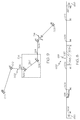
- the scrollbar display process 400 may render and/or display graphical indicators or markers 602, 604, 606, 608, 610, 612 that correspond to the navigational reference points 502, 504, 506, 508, 510, 512 of the flight plan 500 overlying the flight plan scrollbar path 600.
- the scrollbar display process 400 may also render and/or display text or other information associated with the navigational reference points (e.g., the names of the navigational reference points) overlying the flight plan scrollbar path 600 as shown.
- the indicia (e.g., text and/or marker 602, 604, 606, 608, 610, 612) for each navigational reference point of the flight plan 500 is positioned overlying the scrollbar path 600 in a manner that reflects the spatial relationship of the respective navigational reference point to other navigational reference points of the flight plan, or in other words, the indicia are positioned based on the along track distance between the other navigational reference points of the flight plan 500 and the scale of the scrollbar path 600. For example, as shown in FIG.
- a scrollbar path 600 may be configured such that going from left to right along the scrollbar path 600 corresponds to progressing through the flight plan 500 from the initial navigational reference point 502 to the final navigational reference point 512.
- the indicia 602 for the initial navigational reference point 502 of the flight plan 500 is displayed and/or rendered along the left edge of the scrollbar path 600.
- the indicia 604 for the second navigational reference point 504 is positioned overlying the scrollbar path 600 in a manner that reflects the along track distance between the initial navigational reference point 502 and the second navigational reference point 504.
- the scrollbar display process 400 calculates the number of pixels between the indicia 604 for the second navigational reference point 504 and the indicia 602 for the initial navigational reference point 502 (the left edge of the scrollbar path 600) by multiplying the along track distance between the second navigational reference point 504 and the initial navigational reference point 502 by the scale of the scrollbar path 600.
- the number of pixels between the indicia 602 for the initial navigational reference point 502 and the indicia 604 for the second navigational reference point 504 is equal to d 1 ⁇ n d f , where n is the number of horizontal pixels comprising the scrollbar path 600.
- the indicia 606 for the third navigational reference point 506 is positioned overlying the scrollbar path 600 in a manner that reflects the along track distance between the third navigational reference point 506 and the preceding navigational reference points 502, 504.
- the number of pixels between the indicia 606 for the third navigational reference point 506 and the indicia 602 for the initial navigational reference point 502 is equal to the scale of the scrollbar path 600 multiplied by the along track distance between the third navigational reference point 506 and the initial navigational reference point 502, such that the indicia 606 for the third navigational reference point 506 are d 1 + d 2 ⁇ n d f pixels from the indicia 602 for the initial navigational reference point 502 and d 2 ⁇ n d f pixels from the indicia 604 for the second navigational reference point 504.
- the indicia 608, 610, 612 for the remaining navigational reference points 508, 510, 512 are positioned in a similar manner, such that the positioning of the indicia for the respective navigational reference point to the scrollbar path 600 accurately reflects the spatial relationship of the respective navigational reference point to the along track distance of the flight plan 500.
- the indicia 612 for the final navigational reference point 512 is located along the right edge of the scrollbar path 600 or n pixels from the indicia 602 for the initial navigational reference point 502.
- the scrollbar display process 400 continues by displaying and/or rendering a graphical representation of the aircraft overlying the flight plan scrollbar path based on the current location of the aircraft and the scale of the graphical adjustment path (task 410).
- the positioning of the graphical representation of the aircraft with respect to the graphical adjustment path corresponds to the along track distance from the initial navigational reference point to the current location of the aircraft multiplied by the scale of the graphical adjustment path.
- the graphical representation of the aircraft overlying the graphical adjustment path reflects the real-world progress of the aircraft with respect to the flight plan. For example, as shown in FIGS.
- the current location of the aircraft 514 is approaching the second navigational reference point 504 of the flight plan 500 and the graphical representation of the aircraft 614 is positioned overlying the scrollbar path 600 such that the graphical representation of the aircraft 614 is approaching the indicia (e.g., W2 and marker 602) for the second navigational reference point 504.
- the aircraft position 614 with respect to the flight plan scrollbar path 600 corresponds to the along track distance from the initial navigational reference point 502 to the current location of the aircraft 514 multiplied by the scale of the scrollbar path 600.
- a display system 100 may be configured to perform a slider display process 700 and additional tasks, functions, and operations described below.
- the various tasks may be performed by software, hardware, firmware, or any combination thereof.
- the following description may refer to elements mentioned above in connection with FIGS. 1-6 .
- the tasks, functions, and operations may be performed by different elements of the described system, such as the display device 102, the flight management system 108, the user interface 110, the processing architecture 112, the graphics module 114 and/or the database 116. It should be appreciated that any number of additional or alternative tasks may be included, and may be incorporated into a more comprehensive procedure or process having additional functionality not described in detail herein.
- a slider display process 700 initializes by determining a center position for the graphical adjustment element, such as a slider, based on the currently displayed area of the navigational map (task 702).
- the center position of the graphical adjustment element corresponds to the portion of the flight plan currently displayed in the navigational map such that the center position of the graphical adjustment element with respect to graphical adjustment path reflects the portion of the flight plan displayed within the navigational map.
- the center position of the graphical adjustment element corresponds to a point within the flight plan (or a point along the route defined by the flight plan) that is nearest the center location of the currently displayed area of the navigational map.
- the slider display process 700 calculates and/or determines a point 520 within the flight plan 500 that is nearest to the center location 518 of the currently displayed area 516 by computing or otherwise determining a line through the center location 518 that perpendicularly intersects the flight plan 500 and identifying the intersection point 520 as the point nearest the center location 518 of the currently displayed area 516.
- the slider display process 700 calculates and/or determines the along track distance from the initial navigational reference point of the flight plan to the point within the flight plan corresponding to the center location of the currently displayed area, and multiplying the distance by the scale of the flight plan scrollbar path to obtain the center position in pixels.
- the slider display process 700 may calculate and/or determine the along track distance from the initial navigational reference point 502 to the intersection point 520 (e.g., by adding the straight line distance between navigational reference points 502, 504 and the straight line distance between points 504, 520) and multiply the result by the scale of the flight plan scrollbar path 600 to determine the center position 620 (alternatively, the slider position) for the slider 618.
- the slider display process 700 continues by determining and/or calculating a display size (or display dimensions) for the graphical adjustment element based on the size of the currently displayed area of the navigational map and the scale of the graphical adjustment path (task 704).
- the size and/or dimensions of the graphical adjustment element correspond to the range setting and/or field of view for the navigational map such that the size and/or width of the graphical adjustment element reflects the field of view of the currently displayed area.
- a larger range setting results in a larger display size while a smaller range setting results in a smaller display size, as described in greater detail below.
- the display size of the graphical adjustment element corresponds to the along track distance for the portion of the flight plan that lies within the currently displayed area (i.e., the currently displayed portion of the flight plan in the navigational map) such that the size of the graphical adjustment element with respect to the graphical adjustment path reflects the ratio of the along track distance for the portion of the flight plan that lies within the currently displayed area to the total along track distance for the flight plan.
- the display size of the graphical adjustment element corresponds to the along track distance for the portion of the flight plan that lies within the currently displayed area (i.e., the currently displayed portion of the flight plan in the navigational map) such that the size of the graphical adjustment element with respect to the graphical adjustment path reflects the ratio of the along track distance for the portion of the flight plan that lies within the currently displayed area to the total along track distance for the flight plan.
- the slider display process 700 may calculate and/or determine the display size for the slider by determining and/or calculating the along track distance for the portion of the flight plan 500 within the currently displayed area 516 and then multiplying the along track distance for the currently displayed portion of the flight plan by the scale of the scrollbar path 600 to obtain the number of pixels (or pixel width) for the slider.
- the display size of the slider with respect to the flight plan scrollbar path corresponds to the along track distance between points 524, 526 (e.g., the sum of the straight line distance between points 504, 524 and the straight line distance between points 504, 526) of the flight plan 500 that are at the edges of the currently displayed area 516.
- the slider display process 700 continues by displaying and/or rendering the graphical adjustment element overlying the graphical adjustment path with the determined center position and display size (task 706).
- the slider 618 is displayed and/or rendered at a center position 620 that corresponds to the center location 518 of the currently displayed area 516 and a width that corresponds to the portion of the flight plan 500 within the field of view of the currently displayed area 516.
- the number of pixels between the center position 620 of the slider 618 and the marker 604 for the second navigational reference point 504 corresponds to the along track distance between the second navigational reference point 504 and the intersection point 520 multiplied by the scale of the scrollbar path 600.
- the number of pixels between the leading edge 626 of the slider 618 and the trailing edge 624 corresponds to the along track distance between the point 526 of the flight plan 500 at the leading edge of the currently displayed area 516 and the point 524 of the flight plan 500 at the trailing edge of the currently displayed area 516 multiplied by the scale of the scrollbar path 600.
- the slider display process 700 continues by correlating the graphical adjustment element and the navigational map (task 708).
- the slider display process 700 automatically updates the either the navigational map and/or the graphical adjustment element such that the slider position corresponds to the currently displayed area of the navigational map. For example, if navigational map is updated in real-time as the aircraft travels, the center position of the graphical adjustment is automatically adjusted and/or updated such that the center position of the graphical adjustment element is updated substantially in sync with the center location of the displayed area of the navigational map and without any action on behalf of a user.
- the slider display process 700 determines an updated center position for the graphical adjustment element based on the instantaneous center location of the displayed area of the navigational map in a similar manner as described above (e.g., task 702).
- a user may manually reposition and/or adjust the center location of the currently displayed area of the navigational map, for example, by selecting graphical control elements 326 or otherwise manipulating the navigational map 300.
- the slider display process 700 determines an updated center position for the graphical adjustment element based on the updated center location of the currently displayed area of the navigational map, as described above (e.g., task 702).
- the slider display process 700 updates and/or adjusts the navigational map in response to an adjustment of the position of the graphical adjustment element. For example, referring now to FIG. 6 and FIG. 8 , a user may manually reposition and/or adjust the slider position 614 for example, by selecting graphical control elements 630, selecting and/or dragging the slider 618, or otherwise manipulating the flight plan scrollbar path 600 to reposition the slider 618 to an updated slider position 820.
- the slider display process 700 detects an adjustment of the slider position, and in response, automatically adjusts and/or updates the currently displayed area of the navigational map such that it corresponds to the adjusted and/or updated slider position.
- the slider display process 700 calculates the along track distance corresponding to the updated slider position based on the scale of the scrollbar path 600. For example, the slider display process 700 may determine the number of pixels between the updated slider position 820 and the indicia 602 for the initial navigational reference point 502 and divide the result by the scale of the flight plan scrollbar path 600 to obtain the along track distance of the flight plan 500 that corresponds to the updated slider position 820. The slider display process 700 may then determine a point 920 within the flight plan 500 having an along track distance from the initial navigational reference point 502 that corresponds to the updated slider position 820.
- the slider display process 700 determines the updated center location for the currently displayed area 516 as the identified point 920 within the flight plan, such that the currently displayed area 516 of the navigational map is centered about the portion of the flight plan 500 that corresponds to the updated slider position 820.
- the slider display process 700 may also update the vertical profile synchronously with the navigational map, such that the vertical profile reflects the portion of the flight plan within the currently displayed area. For example, the vertical profile may be updated to reflect the vertical profile for flying from a point 924 within the flight plan 500 at the trailing edge of the displayed area 516 to the a point 926 within the flight plan 500 at the leading edge of the displayed area 516.
- the width or size of the slider 618 may be updated to reflect the along track distance for the portion of the flight plan within the displayed area 516 about the updated center location 920, such that the leading edge 826 of the slider 618 corresponds to a point 926 within the flight plan 500 at the leading edge of the currently displayed area 516 while the trailing edge 824 of the slider 618 corresponds to the a point 924 within the flight plan 500 at the trailing edge of the currently displayed area 516.
- the slider display process 700 also updates and/or adjusts the size of the graphical adjustment element in response to an adjustment of the range setting and/or scale of the navigational map.
- a user may manipulate the user interface 110 to increase and/or decrease the range setting for the navigational map.
- the slider display process 700 increases and/or decreases the size (or width) of the graphical adjustment element such that the size of the graphical adjustment element corresponds to the size of the currently displayed area. For example, referring now to FIG. 5 and FIG. 10 , a user may decrease the range setting of the navigational map to adjust the reduce the field of view and/or size of the currently displayed area 516 to a smaller geographic area 1016. Referring now to FIG. 11 and FIG.
- the slider display process 700 reduces the width of the slider 618 in a corresponding manner such that the display size or width of the slider 618 with respect to the flight plan scrollbar path 600 corresponds to the along track distance between points 1024, 1026 of the flight plan 500 that are at the edges of the currently displayed area 1016.
- the slider display process 700 may calculate and/or determine the width for the slider by determining and/or calculating the along track distance for the portion of the flight plan 500 within the currently displayed area 1016 and then multiplying the along track distance for the currently displayed portion of the flight plan by the scale of the scrollbar path 600 to obtain the number of pixels (or pixel width) for the slider 618 (e.g., task 704), as described above.
- the number of pixels between the leading edge 1126 of the slider 618 and the trailing edge 1124 corresponds to the along track distance between the point 1026 within the flight plan 500 at the leading edge of the currently displayed area 1016 and the point 1024 within the flight plan 500 at the trailing edge of the currently displayed area 1016 multiplied by the scale of the scrollbar path 600.
- the scrollbar e.g., slider and/or scrollbar path
- the graphical adjustment element e.g., the slider
- the graphical adjustment path e.g., scrollbar path
- the width and/or size of the graphical adjustment element reflects the size or amount of geographic area currently displayed on the navigational map.
- a graphical representation of the aircraft is also displayed overlying the scrollbar which provides additional situational awareness as to the progress and/or status of the aircraft within the flight plan.
Claims (7)
- Verfahren zum Darstellen, auf einer Anzeigevorrichtung (102) im Zusammenhang mit einem Flugzeug (118), von Informationen in Bezug auf einen Flugplan (306, 500), der mehrere Navigationsreferenzpunkte (502-512) aufweist, die einen Flugweg für das Flugzeug (118) definieren, einschließlich eines Anfangsnavigationsreferenzpunktes (502) und eines Endnavigationsreferenzpunktes (512), wobei das Verfahren Folgendes aufweist:Anzeigen (202) einer Navigationskarte (300) auf der Anzeigevorrichtung (102), wobei die Navigationskarte (300) einen angezeigten Bereich (516) aufweist, der einem geographischen Gebiet entspricht; undAnzeigen (206) eines graphischen Anpassungspfades (312, 600) auf der Anzeigevorrichtung (102), wobei der graphische Anpassungspfad (312, 600) einer ersten Distanz entlang des Kurses zwischen dem Anfangsnavigationsreferenzpunkt (502) und dem Endnavigationsreferenzpunkt (512) entspricht;Anzeigen (210) eines Anpassungselementes (318, 618), welches den graphischen Anpassungspfad (600) auf der Anzeigevorrichtung (102) überlagert, wobei das Anpassungselement (318, 618) das Blättern der Navigationskarte (300) entlang des Flugplans (306, 500) ermöglicht, wobei:eine Position des Anpassungselementes (318, 618) in Bezug auf den graphischen Anpassungspfad (312, 600) einer zweiten Distanz entlang des Kurses von dem Anfangsnavigationsreferenzpunkt (502) des Flugplans (306, 500) zu dem geographischen Gebiet entspricht; unddie zweite Distanz entlang des Kurses entlang des Flugplans (306, 500) gemessen wird;Anzeigen einer graphischen Darstellung eines Flugzeugs (314, 614), welche den graphischen Anpassungspfad (312, 600) überlagert, an einer Position, die einer dritten Distanz entlang des Kurses von dem ersten Anfangsnavigationsreferenzpunkt (502) zu einer aktuellen Position des Flugzeugs (118) entspricht;Anzeigen (204) eines vertikalen Profils (310) auf der Anzeigevorrichtung (102), wobei das vertikale Profil (310) dem angezeigten Bereich (516, 1016) entspricht, undals Reaktion auf eine Anpassung der Position des Anpassungselementes (318, 618), die in einer aktualisierten Position (820) für das Anpassungselement (318, 618) resultiert,Berechnen einer vierten Distanz entlang des Kurses von dem Anfangsnavigationsreferenzpunkt (502), die der aktualisierten Position (820) des Anpassungselementes (318, 618) entspricht, basierend auf einer Skala des graphischen Anpassungspfades (312, 600);Bestimmen eines Punktes (920) innerhalb des Flugplans (306, 500) mit der vierten Distanz entlang des Kurses von dem Anfangsnavigationsreferenzpunkt (502); undautomatisches Anpassen einer zentralen Position (518) des angezeigten Bereiches (516) als Reaktion auf die Anpassung der Position des Anpassungselementes (318, 618) durch Bestimmen einer aktualisierten zentralen Position für den angezeigten Bereich (516) als Punkt (920) innerhalb des Flugplans (500), wobei das vertikale Profil (310) automatisch derart angepasst wird, dass es einem Abschnitt des Flugplans innerhalb des angezeigten Bereiches (516) entspricht, als Reaktion auf die Anpassung der Position des Anpassungselementes (318, 618).
- Verfahren nach Anspruch 1, wobei das Verfahren ferner Folgendes aufweist:Identifizieren eines Punktes (520) innerhalb des Flugplans, der dem angezeigten Bereich (516) entspricht;Berechnen der Distanz entlang des Kurses von dem Punkt (520) zu dem Anfangsnavigationsreferenzpunkt (502) zum Erhalten der zweiten Distanz entlang des Kurses zwischen dem angezeigten Bereich (516) und dem Anfangsnavigationsreferenzpunkt (502); undBestimmen der Position des Anpassungselementes (318, 618) basierend auf einem Verhältnis der zweiten Distanz entlang des Kurses zwischen dem angezeigten Bereich (516) und dem ersten Navigationsreferenzpunkt (502) zu der ersten Distanz entlang des Kurses.
- Verfahren nach Anspruch 2, wobei der graphische Anpassungspfad (312, 600) mit einer ersten Zahl von Pixeln angezeigt wird, wobei das Bestimmen der Position des Anpassungselementes (618) Folgendes aufweist:Bestimmen der Skala des graphischen Anpassungspfades (312, 600) basierend auf einem Verhältnis der ersten Zahl von Pixeln zu der ersten Distanz entlang des Kurses; undBerechnen einer zweiten Zahl von Pixeln basierend auf der zweiten Distanz entlang des Kurses zwischen dem angezeigten Bereich (516) und dem Anfangsnavigationsreferenzpunkt (502) und der Skala des graphischen Anpassungspfades (312, 600), wobei das Anpassungselement (318, 618) entsprechend der zweiten Zahl von Pixeln an der Position (620) angezeigt wird.
- Verfahren nach Anspruch 1, welches ferner das Anzeigen einer graphischen Darstellung des Flugzeugs (314, 614), welche den graphischen Anpassungspfad (600) überlagert, aufweist, wobei die graphische Darstellung des Flugzeugs (314, 614), welche den graphischen Anpassungspfad (312, 600) überlagert, an einer Flugzeugposition einer vierten Distanz entlang des Kurses zwischen einer aktuellen Position des Flugzeugs (118) und dem Anfangsnavigationsreferenzpunkt (502) entspricht, derart, dass die Flugzeugposition in Bezug auf den graphischen Anpassungspfad (312, 600) der vierten Distanz entlang des Kurses entspricht.
- Verfahren nach Anspruch 1, welches ferner Folgendes aufweist:Bestimmen einer vierten Distanz entlang des Kurses für einen ersten Abschnitt des Flugplans innerhalb des angezeigten Bereiches (516); undBerechnen einer Anzeigegröße für das Anpassungselement (318, 618) basierend auf der vierten Distanz entlang des Kurses für den ersten Abschnitt des Flugplans innerhalb des angezeigten Bereiches (516) und der Skala des graphischen Anpassungspfades (312, 600).
- Verfahren nach Anspruch 1, welches ferner, als Reaktion auf die Anpassung der Position des Anpassungselementes (318, 618) auf die aktualisierte Position, Folgendes aufweist:Bestimmen eines aktualisierten Abschnittes der Route (306, 500) mit einer vierten Distanz entlang des Kurses von dem Anfangsnavigationsreferenzpunkt (302, 502), die der aktualisierten Position des Anpassungselementes (318, 618) entspricht; undAktualisieren des angezeigten Bereiches (516) der Navigationskarte (300), derart, dass er einen aktualisierten Abschnitt der Route (306, 500) von einem ersten Punkt (924) innerhalb des Flugplans (500) an einer Hinterkante des angezeigten Bereiches (516) zu einem zweiten Punkt (926) innerhalb des Flugplans (500) an einer Vorderkante des angezeigten Bereiches (516) aufweist, wobei das vertikale Profil (310) automatisch derart angepasst wird, dass es das vertikale Profil (310) des aktualisierten Abschnittes der Route (306, 500) zum Fliegen von dem zweiten Punkt (924) zu dem ersten Punkt (926) anzeigt.
- Anzeigesystem (100), welches eine Anzeigevorrichtung (102) im Zusammenhang mit einem Flugzeug (118) aufweist, zum Anzeigen von Informationen in Bezug auf einen Flugplan (306, 500), welcher mehrere Navigationsreferenzpunkte (502-512) aufweist, die einen Flugweg für das Flugzeug (118) definieren, einschließlich eines Anfangsnavigationsreferenzpunktes (502) und eines Endnavigationsreferenzpunktes (512), wobei Folgendes auf der Anzeigevorrichtung (102) wiedergegeben wird:eine Navigationskarte (300) mit einem angezeigten Bereich (516), der einem geographischen Gebiet entspricht;ein graphischer Anpassungspfad (312, 600), der einer ersten Distanz entlang des Kurses von dem Anfangsnavigationsreferenzpunkt (502) zu dem Endnavigationsreferenzpunkt (512) des Flugplans (306, 500) entspricht;ein Anpassungselement (318, 618), welches das Blättern der Navigationskarte (300) entlang einer Route (306, 500) ermöglicht, welche den graphischen Anpassungspfad (312, 600) überlagert, wobei das Anpassungselement (318, 618) mit Bezug auf den graphischen Anpassungspfad (312, 600) in einer Art und Weise positioniert ist, die einer zweiten Distanz entlang des Kurses von dem Anfangsnavigationsreferenzpunkt (502) zu dem geographischen Gebiet entspricht;eine graphische Darstellung eines Flugzeugs (314, 614), welche den graphischen Anpassungspfad (312, 600) überlagert, an einer Position, welche einer dritten Distanz entlang des Kurses von dem Anfangsnavigationsreferenzpunkt (502) zu einer aktuellen Position des Flugzeugs (118) entspricht; undeine graphische Darstellung eines vertikalen Profils (310), die einem Abschnitt der Route (306, 500) innerhalb des geographischen Gebietes entspricht, wobei als Reaktion auf eine Anpassung der Position des Anpassungselementes (318, 618) auf eine aktualisierte Position (820) für das Anpassungselement (618):eine zentrale Position (518) des angezeigten Bereiches automatisch auf einen Punkt (920) innerhalb des Flugplans (500), welcher eine vierte Distanz entlang des Kurses von dem Anfangsnavigationsreferenzpunkt (502) aufweist, angepasst wird, die der aktualisierten Position (820) des Anpassungselementes (318, 618) entspricht, basierend auf einer Skala des graphischen Anpassungspfades (312, 600); unddas vertikale Profil (310) automatisch derart angepasst wird, dass es dem Abschnitt der Route (306, 500) innerhalb des angezeigten Bereiches entspricht, als Reaktion auf die Anpassung der Position des Anpassungselementes (318, 618).
Applications Claiming Priority (1)
| Application Number | Priority Date | Filing Date | Title |
|---|---|---|---|
| US12/500,432 US9851219B2 (en) | 2009-07-09 | 2009-07-09 | Methods and systems for route-based scrolling of a navigational map |
Publications (3)
| Publication Number | Publication Date |
|---|---|
| EP2273236A2 EP2273236A2 (de) | 2011-01-12 |
| EP2273236A3 EP2273236A3 (de) | 2013-05-08 |
| EP2273236B1 true EP2273236B1 (de) | 2016-09-21 |
Family
ID=42797518
Family Applications (1)
| Application Number | Title | Priority Date | Filing Date |
|---|---|---|---|
| EP10167593.2A Active EP2273236B1 (de) | 2009-07-09 | 2010-06-28 | Verfahren und Systeme zur routenbasierten Blättern einer Navigationskarte |
Country Status (2)
| Country | Link |
|---|---|
| US (1) | US9851219B2 (de) |
| EP (1) | EP2273236B1 (de) |
Cited By (1)
| Publication number | Priority date | Publication date | Assignee | Title |
|---|---|---|---|---|
| RU2747760C1 (ru) * | 2020-07-14 | 2021-05-13 | Российская Федерация, от имени которой выступает Министерство промышленности и торговли Российской Федерации (Минпромторг России) | Комплексная система подготовки и корректировки полетных заданий, навигации и управления летательного аппарата |
Families Citing this family (32)
| Publication number | Priority date | Publication date | Assignee | Title |
|---|---|---|---|---|
| US9851219B2 (en) * | 2009-07-09 | 2017-12-26 | Honeywell International Inc. | Methods and systems for route-based scrolling of a navigational map |
| US8788196B1 (en) * | 2009-11-16 | 2014-07-22 | The Boeing Company | Presentation of a vehicle on a chart |
| US8412392B2 (en) * | 2010-02-24 | 2013-04-02 | Honeywell International Inc. | Methods and systems for displaying predicted downpath parameters in a vertical profile display |
| KR101572892B1 (ko) * | 2010-05-06 | 2015-11-30 | 엘지전자 주식회사 | 이동 단말기 및 이것의 영상 디스플레이 방법 |
| US20120010765A1 (en) * | 2010-07-07 | 2012-01-12 | Honeywell International Inc. | System for displaying a procedure to an aircraft operator during a flight of an aircraft |
| US8780091B2 (en) * | 2011-02-10 | 2014-07-15 | General Electric Company | Methods and systems for controlling an information display |
| US9146133B2 (en) | 2011-06-06 | 2015-09-29 | Honeywell International Inc. | Methods and systems for displaying procedure information on an aircraft display |
| US10041802B1 (en) * | 2011-09-28 | 2018-08-07 | The Boeing Company | Methods and systems for depicting own ship |
| WO2013085275A1 (ko) * | 2011-12-05 | 2013-06-13 | 엘지전자 주식회사 | 무선 통신 시스템에서 방향성에 기반한 가용 채널 정보 송수신 방법 및 장치 |
| US8797190B2 (en) * | 2012-07-26 | 2014-08-05 | General Electric Company | Method for displaying a user entered flight path |
| US8843306B1 (en) * | 2012-11-28 | 2014-09-23 | The Boeing Company | Airspace fix formation display |
| US9448702B2 (en) | 2013-05-08 | 2016-09-20 | Honeywell International Inc. | Methods and systems for selecting a displayed aircraft approach or departure |
| FR3015023B1 (fr) * | 2013-12-18 | 2016-01-15 | Dassault Aviat | Systeme d'aide a la preparation d'une mission d'un ou plusieurs aeronefs ou groupes d'aeronefs et procede correspondant |
| US10431105B2 (en) * | 2014-01-07 | 2019-10-01 | Honeywell International Inc. | Enhanced awareness of obstacle proximity |
| US10963133B2 (en) | 2014-01-07 | 2021-03-30 | Honeywell International Inc. | Enhanced awareness of obstacle proximity |
| US9563944B2 (en) * | 2014-04-02 | 2017-02-07 | Honeywell International Inc. | System and method for displaying optimized ownship position on a navigation display |
| US9335917B2 (en) * | 2014-06-09 | 2016-05-10 | Honeywell International Inc. | System and method for providing enhanced HMI navigation |
| US9593961B2 (en) * | 2014-08-13 | 2017-03-14 | Honeywell International Inc. | System and method for integrated time based notification for improved situational awareness |
| WO2016061774A1 (zh) * | 2014-10-22 | 2016-04-28 | 深圳市大疆创新科技有限公司 | 一种飞行航线设置方法及装置 |
| US10414402B2 (en) | 2015-03-25 | 2019-09-17 | Volvo Construction Equipment Ab | Method for controlling gear shifting of a working machine |
| FR3036476B1 (fr) * | 2015-05-19 | 2018-06-15 | Dassault Aviation | Systeme de visualisation d'informations relatives a un vol d'un aeronef et procede associe |
| KR102482595B1 (ko) * | 2015-12-17 | 2022-12-30 | 삼성전자주식회사 | 지도 정보 제공 방법 및 이를 지원하는 전자 장치 |
| FR3051898B1 (fr) * | 2016-05-24 | 2020-12-11 | Airbus Operations Sas | Ensemble de gestion de vol pour un aeronef et procede de securisation de donnees du monde ouvert a l'aide d'un tel ensemble |
| US20180096532A1 (en) * | 2016-10-03 | 2018-04-05 | Honeywell International Inc. | System and method for virtual reality simulation of vehicle travel |
| EP3322149B1 (de) * | 2016-11-10 | 2023-09-13 | Tata Consultancy Services Limited | Erzeugung von personalisierten landkarten mit echtzeitnachrichten und standorten von gleichzeitigen benutzern |
| CN106643755A (zh) * | 2016-12-20 | 2017-05-10 | 南京国电南自电网自动化有限公司 | 一种基于封闭区域平面图的导航地图生成方法 |
| CN106643698A (zh) * | 2016-12-20 | 2017-05-10 | 南京国电南自电网自动化有限公司 | 一种基于预置二维码标识的封闭区域精确导航方法 |
| US10467912B2 (en) * | 2017-03-14 | 2019-11-05 | Honeywell International Inc. | System and method to revise vertical profile of a flight plan |
| CN108109437B (zh) * | 2018-01-24 | 2021-01-12 | 广东容祺智能科技有限公司 | 一种基于地图特征的无人机自主航线提取生成方法 |
| US10810888B2 (en) * | 2018-06-08 | 2020-10-20 | Honeywell International Inc. | Automatic from-waypoint updating system and method |
| US20220139238A1 (en) * | 2020-10-29 | 2022-05-05 | Rockwell Collins, Inc. | Flight path inspection display |
| CN112857371A (zh) * | 2020-12-29 | 2021-05-28 | 上海企树网络科技有限公司 | 一种导航二维码生成方法、园区导航方法及装置 |
Family Cites Families (47)
| Publication number | Priority date | Publication date | Assignee | Title |
|---|---|---|---|---|
| US3652836A (en) * | 1968-03-22 | 1972-03-28 | Hughes Aircraft Co | Navigation director system |
| US3668623A (en) * | 1969-08-14 | 1972-06-06 | Bendix Corp | Aircraft vertical flight position display instrument |
| US4673929A (en) * | 1984-04-16 | 1987-06-16 | Gould Inc. | Circuit for processing digital image data in a high resolution raster display system |
| US4803464A (en) * | 1984-04-16 | 1989-02-07 | Gould Inc. | Analog display circuit including a wideband amplifier circuit for a high resolution raster display system |
| US4692869A (en) * | 1985-03-28 | 1987-09-08 | The Boeing Company | Aircraft navigational systems and methods for creating navigational guidepoints |
| US5184123A (en) * | 1988-03-03 | 1993-02-02 | Robert Bosch Gmbh | Method of and arrangement for representing travel guiding information |
| US5041982A (en) * | 1988-12-12 | 1991-08-20 | Honeywell Inc. | Edit area algorithm for navigation display of an electronic flight instrument system |
| JP3155022B2 (ja) * | 1991-04-23 | 2001-04-09 | パイオニア株式会社 | 車載ナビゲーション装置 |
| DE69313167T2 (de) * | 1992-02-18 | 1998-01-15 | Pioneer Electronic Corp | Navigationsvorrichtung mit verbesserter Positionsanzeigefunktion |
| US5369589A (en) * | 1993-09-15 | 1994-11-29 | Trimble Navigation Limited | Plural information display for navigation |
| EP0660289B1 (de) | 1993-12-27 | 2001-10-04 | Aisin Aw Co., Ltd. | Kartenanzeigesystem |
| US5995901A (en) * | 1996-09-30 | 1999-11-30 | Rockwell International Corporation | Automatic view adjusting flight plan display |
| US6199015B1 (en) * | 1996-10-10 | 2001-03-06 | Ames Maps, L.L.C. | Map-based navigation system with overlays |
| US5978715A (en) * | 1997-10-15 | 1999-11-02 | Dassault Aviation | Apparatus and method for aircraft display and control |
| US6038498A (en) * | 1997-10-15 | 2000-03-14 | Dassault Aviation | Apparatus and mehod for aircraft monitoring and control including electronic check-list management |
| US6112141A (en) * | 1997-10-15 | 2000-08-29 | Dassault Aviation | Apparatus and method for graphically oriented aircraft display and control |
| US6320579B1 (en) * | 1998-12-30 | 2001-11-20 | Honeywell International Inc. | Cockpit display having 3D flight path error symbology |
| JP2000292180A (ja) | 1999-04-02 | 2000-10-20 | Kenwood Corp | 車載ナビゲーション装置 |
| US6799095B1 (en) * | 1999-09-08 | 2004-09-28 | Rockwell Collins | Method and apparatus for interactively displaying a route window for a flight management system |
| US6389355B1 (en) * | 1999-09-14 | 2002-05-14 | Honeywell International Inc. | Methods and apparatus for graphical display and editing of flight plans |
| US6353794B1 (en) * | 1999-10-19 | 2002-03-05 | Ar Group, Inc. | Air travel information and computer data compilation, retrieval and display method and system |
| US7664601B2 (en) * | 1999-11-10 | 2010-02-16 | Honeywell International Inc. | Weather incident prediction |
| JP2002054942A (ja) * | 2000-08-09 | 2002-02-20 | Honda Motor Co Ltd | 残距離メータ |
| JP2003177028A (ja) | 2001-12-11 | 2003-06-27 | Nissan Motor Co Ltd | 電子地図表示装置 |
| FR2837591B1 (fr) * | 2002-03-20 | 2004-07-02 | Airbus France | Dispositif de visualisation d'un aeroport |
| US7725258B2 (en) * | 2002-09-20 | 2010-05-25 | M7 Visual Intelligence, L.P. | Vehicle based data collection and processing system and imaging sensor system and methods thereof |
| WO2004028134A2 (en) * | 2002-09-20 | 2004-04-01 | M7 Visual Intelligence, Lp | Vehicule based data collection and porcessing system |
| US7239311B2 (en) * | 2002-09-26 | 2007-07-03 | The United States Government As Represented By The Secretary Of The Navy | Global visualization process (GVP) and system for implementing a GVP |
| US7417641B1 (en) * | 2002-10-16 | 2008-08-26 | Rockwell Collins, Inc. | Aeronautical chart display apparatus and method |
| US7321824B1 (en) * | 2002-12-30 | 2008-01-22 | Aol Llc | Presenting a travel route using more than one presentation style |
| US7343232B2 (en) * | 2003-06-20 | 2008-03-11 | Geneva Aerospace | Vehicle control system including related methods and components |
| KR100811232B1 (ko) * | 2003-07-18 | 2008-03-07 | 엘지전자 주식회사 | 턴 바이 턴 네비게이션 시스템 및 차기 안내방법 |
| EP1669719B1 (de) * | 2003-09-30 | 2009-09-23 | Kabushiki Kaisha Kenwood | Führungsroutensuchverfahren |
| US20060005147A1 (en) * | 2004-06-30 | 2006-01-05 | Hammack Jason L | Methods and systems for controlling the display of maps aboard an aircraft |
| US7382288B1 (en) * | 2004-06-30 | 2008-06-03 | Rockwell Collins, Inc. | Display of airport signs on head-up display |
| US7209070B2 (en) * | 2004-10-07 | 2007-04-24 | Honeywell International, Inc. | System and method for enhanced situational awareness of terrain in a vertical situation display |
| JP2006112962A (ja) * | 2004-10-15 | 2006-04-27 | Aisin Aw Co Ltd | 運転支援方法及び運転支援装置 |
| US7403843B2 (en) * | 2004-12-13 | 2008-07-22 | Honeywell International Inc. | Systems and methods for automated deselection of flight plan information from a display |
| JP4157594B2 (ja) * | 2006-08-01 | 2008-10-01 | 松下電器産業株式会社 | 地図情報表示装置及びその方法 |
| DE112007002389B4 (de) * | 2006-12-04 | 2012-04-19 | Mitsubishi Electric Corp. | Navigationsvorrichtung |
| JP2008209208A (ja) * | 2007-02-26 | 2008-09-11 | Denso Corp | カーナビゲーション装置 |
| JP5082545B2 (ja) | 2007-03-30 | 2012-11-28 | 株式会社Jvcケンウッド | ナビゲーション装置及びプログラム |
| US7801675B2 (en) * | 2007-07-13 | 2010-09-21 | Dash Navigation, Inc. | System and method of identifying portions of roads |
| US9354077B2 (en) * | 2008-05-20 | 2016-05-31 | Honeywell International Inc. | Navigation system |
| US8099202B1 (en) * | 2008-06-06 | 2012-01-17 | Rockwell Collins, Inc. | System and method for providing a final approach curtain |
| US7852236B2 (en) * | 2008-07-31 | 2010-12-14 | Honeywell International Inc. | Aircraft synthetic vision system for approach and landing |
| US9851219B2 (en) * | 2009-07-09 | 2017-12-26 | Honeywell International Inc. | Methods and systems for route-based scrolling of a navigational map |
-
2009
- 2009-07-09 US US12/500,432 patent/US9851219B2/en active Active
-
2010
- 2010-06-28 EP EP10167593.2A patent/EP2273236B1/de active Active
Non-Patent Citations (1)
| Title |
|---|
| None * |
Cited By (1)
| Publication number | Priority date | Publication date | Assignee | Title |
|---|---|---|---|---|
| RU2747760C1 (ru) * | 2020-07-14 | 2021-05-13 | Российская Федерация, от имени которой выступает Министерство промышленности и торговли Российской Федерации (Минпромторг России) | Комплексная система подготовки и корректировки полетных заданий, навигации и управления летательного аппарата |
Also Published As
| Publication number | Publication date |
|---|---|
| EP2273236A3 (de) | 2013-05-08 |
| EP2273236A2 (de) | 2011-01-12 |
| US9851219B2 (en) | 2017-12-26 |
| US20110010082A1 (en) | 2011-01-13 |
Similar Documents
| Publication | Publication Date | Title |
|---|---|---|
| EP2273236B1 (de) | Verfahren und Systeme zur routenbasierten Blättern einer Navigationskarte | |
| US9852493B2 (en) | Methods and systems for displaying a vertical profile for an aircraft procedure with nonuniform scaling | |
| EP2362289B1 (de) | Verfahren und Systeme zur Anzeige vorhersagbarer Parameter stromabwärts in einer vertikalen Profilanzeige | |
| EP2679959B1 (de) | Avionikanzeigesystem zur bereitstellung erweiterter flugplanverwaltung | |
| EP2922046B1 (de) | System und Verfahren zur Bereitstellung verbesserter Flugplanverwaltung | |
| US9046369B2 (en) | Methods and systems for updating a map in response to selection of content for display on the map | |
| EP1896797B1 (de) | Primäre fluganzeige mit perspektivenansicht mit geländeverfolgungslinien | |
| EP3205980A1 (de) | Verfahren und systeme zur erleichterung des haltens eines nicht verfügbaren ziels | |
| EP2955484A1 (de) | System und verfahren zur bereitstellung von verbesserter hmi-navigation | |
| EP3205981A1 (de) | Verfahren und systeme für sichere landung auf einem umleitungsflughafen | |
| EP2779140B1 (de) | System und Verfahren zur Alarmierung des Flugzeugpersonals vor Schwellenhöhen | |
| US8810435B2 (en) | Apparatus and method for displaying a helicopter approach to an airport landing pad | |
| EP1764759A1 (de) | Systeme und Verfahren zur Anzeige von geschütztem oder gesperrtem Luftraum in einem Flugzeug | |
| US20170138759A1 (en) | Enhanced instrument procedure visualization | |
| EP2741053A2 (de) | System und Verfahren zur graphischen Erzeugung eines Annäherungs- oder eines Startkurses | |
| EP3023741B1 (de) | System und verfahren zur exozentrischen anzeige von integrierter navigation | |
| US11574549B2 (en) | Composite vertical profile display systems and methods | |
| EP3657131B1 (de) | Verfahren und systeme zur darstellung von wegpunktlisten | |
| EP2927639B1 (de) | Avioniksystem und verfahren zur anzeige einer optimierten eigenfahrzeugsposition auf einer navigationsanzeige | |
| US9448702B2 (en) | Methods and systems for selecting a displayed aircraft approach or departure | |
| EP3985646A1 (de) | Systeme und verfahren zur anzeige von zusammengesetzten vertikalen profilen |
Legal Events
| Date | Code | Title | Description |
|---|---|---|---|
| PUAI | Public reference made under article 153(3) epc to a published international application that has entered the european phase |
Free format text: ORIGINAL CODE: 0009012 |
|
| 17P | Request for examination filed |
Effective date: 20100628 |
|
| AK | Designated contracting states |
Kind code of ref document: A2 Designated state(s): AL AT BE BG CH CY CZ DE DK EE ES FI FR GB GR HR HU IE IS IT LI LT LU LV MC MK MT NL NO PL PT RO SE SI SK SM TR |
|
| AX | Request for extension of the european patent |
Extension state: BA ME RS |
|
| PUAL | Search report despatched |
Free format text: ORIGINAL CODE: 0009013 |
|
| AK | Designated contracting states |
Kind code of ref document: A3 Designated state(s): AL AT BE BG CH CY CZ DE DK EE ES FI FR GB GR HR HU IE IS IT LI LT LU LV MC MK MT NL NO PL PT RO SE SI SK SM TR |
|
| AX | Request for extension of the european patent |
Extension state: BA ME RS |
|
| RIC1 | Information provided on ipc code assigned before grant |
Ipc: G01C 23/00 20060101AFI20130402BHEP Ipc: G01C 21/36 20060101ALI20130402BHEP |
|
| 17Q | First examination report despatched |
Effective date: 20131115 |
|
| RAP1 | Party data changed (applicant data changed or rights of an application transferred) |
Owner name: HONEYWELL INTERNATIONAL INC. |
|
| RIC1 | Information provided on ipc code assigned before grant |
Ipc: G08G 5/00 20060101ALN20160104BHEP Ipc: G01C 23/00 20060101AFI20160104BHEP |
|
| GRAP | Despatch of communication of intention to grant a patent |
Free format text: ORIGINAL CODE: EPIDOSNIGR1 |
|
| RIC1 | Information provided on ipc code assigned before grant |
Ipc: G01C 23/00 20060101AFI20160223BHEP Ipc: G08G 5/00 20060101ALN20160223BHEP |
|
| RIC1 | Information provided on ipc code assigned before grant |
Ipc: G01C 23/00 20060101AFI20160307BHEP Ipc: G08G 5/00 20060101ALN20160307BHEP |
|
| INTG | Intention to grant announced |
Effective date: 20160321 |
|
| GRAJ | Information related to disapproval of communication of intention to grant by the applicant or resumption of examination proceedings by the epo deleted |
Free format text: ORIGINAL CODE: EPIDOSDIGR1 |
|
| GRAS | Grant fee paid |
Free format text: ORIGINAL CODE: EPIDOSNIGR3 |
|
| GRAP | Despatch of communication of intention to grant a patent |
Free format text: ORIGINAL CODE: EPIDOSNIGR1 |
|
| INTC | Intention to grant announced (deleted) | ||
| GRAA | (expected) grant |
Free format text: ORIGINAL CODE: 0009210 |
|
| RIC1 | Information provided on ipc code assigned before grant |
Ipc: G08G 5/00 20060101ALN20160721BHEP Ipc: G01C 23/00 20060101AFI20160721BHEP |
|
| INTG | Intention to grant announced |
Effective date: 20160805 |
|
| AK | Designated contracting states |
Kind code of ref document: B1 Designated state(s): AL AT BE BG CH CY CZ DE DK EE ES FI FR GB GR HR HU IE IS IT LI LT LU LV MC MK MT NL NO PL PT RO SE SI SK SM TR |
|
| REG | Reference to a national code |
Ref country code: GB Ref legal event code: FG4D |
|
| REG | Reference to a national code |
Ref country code: CH Ref legal event code: EP |
|
| REG | Reference to a national code |
Ref country code: AT Ref legal event code: REF Ref document number: 831413 Country of ref document: AT Kind code of ref document: T Effective date: 20161015 |
|
| REG | Reference to a national code |
Ref country code: IE Ref legal event code: FG4D |
|
| REG | Reference to a national code |
Ref country code: DE Ref legal event code: R096 Ref document number: 602010036535 Country of ref document: DE |
|
| REG | Reference to a national code |
Ref country code: LT Ref legal event code: MG4D Ref country code: NL Ref legal event code: MP Effective date: 20160921 |
|
| PG25 | Lapsed in a contracting state [announced via postgrant information from national office to epo] |
Ref country code: NO Free format text: LAPSE BECAUSE OF FAILURE TO SUBMIT A TRANSLATION OF THE DESCRIPTION OR TO PAY THE FEE WITHIN THE PRESCRIBED TIME-LIMIT Effective date: 20161221 Ref country code: LT Free format text: LAPSE BECAUSE OF FAILURE TO SUBMIT A TRANSLATION OF THE DESCRIPTION OR TO PAY THE FEE WITHIN THE PRESCRIBED TIME-LIMIT Effective date: 20160921 Ref country code: FI Free format text: LAPSE BECAUSE OF FAILURE TO SUBMIT A TRANSLATION OF THE DESCRIPTION OR TO PAY THE FEE WITHIN THE PRESCRIBED TIME-LIMIT Effective date: 20160921 |
|
| REG | Reference to a national code |
Ref country code: AT Ref legal event code: MK05 Ref document number: 831413 Country of ref document: AT Kind code of ref document: T Effective date: 20160921 |
|
| PG25 | Lapsed in a contracting state [announced via postgrant information from national office to epo] |
Ref country code: LV Free format text: LAPSE BECAUSE OF FAILURE TO SUBMIT A TRANSLATION OF THE DESCRIPTION OR TO PAY THE FEE WITHIN THE PRESCRIBED TIME-LIMIT Effective date: 20160921 Ref country code: SE Free format text: LAPSE BECAUSE OF FAILURE TO SUBMIT A TRANSLATION OF THE DESCRIPTION OR TO PAY THE FEE WITHIN THE PRESCRIBED TIME-LIMIT Effective date: 20160921 Ref country code: NL Free format text: LAPSE BECAUSE OF FAILURE TO SUBMIT A TRANSLATION OF THE DESCRIPTION OR TO PAY THE FEE WITHIN THE PRESCRIBED TIME-LIMIT Effective date: 20160921 Ref country code: GR Free format text: LAPSE BECAUSE OF FAILURE TO SUBMIT A TRANSLATION OF THE DESCRIPTION OR TO PAY THE FEE WITHIN THE PRESCRIBED TIME-LIMIT Effective date: 20161222 |
|
| PG25 | Lapsed in a contracting state [announced via postgrant information from national office to epo] |
Ref country code: RO Free format text: LAPSE BECAUSE OF FAILURE TO SUBMIT A TRANSLATION OF THE DESCRIPTION OR TO PAY THE FEE WITHIN THE PRESCRIBED TIME-LIMIT Effective date: 20160921 Ref country code: EE Free format text: LAPSE BECAUSE OF FAILURE TO SUBMIT A TRANSLATION OF THE DESCRIPTION OR TO PAY THE FEE WITHIN THE PRESCRIBED TIME-LIMIT Effective date: 20160921 |
|
| REG | Reference to a national code |
Ref country code: FR Ref legal event code: PLFP Year of fee payment: 8 |
|
| PG25 | Lapsed in a contracting state [announced via postgrant information from national office to epo] |
Ref country code: SK Free format text: LAPSE BECAUSE OF FAILURE TO SUBMIT A TRANSLATION OF THE DESCRIPTION OR TO PAY THE FEE WITHIN THE PRESCRIBED TIME-LIMIT Effective date: 20160921 Ref country code: CZ Free format text: LAPSE BECAUSE OF FAILURE TO SUBMIT A TRANSLATION OF THE DESCRIPTION OR TO PAY THE FEE WITHIN THE PRESCRIBED TIME-LIMIT Effective date: 20160921 Ref country code: SM Free format text: LAPSE BECAUSE OF FAILURE TO SUBMIT A TRANSLATION OF THE DESCRIPTION OR TO PAY THE FEE WITHIN THE PRESCRIBED TIME-LIMIT Effective date: 20160921 Ref country code: IS Free format text: LAPSE BECAUSE OF FAILURE TO SUBMIT A TRANSLATION OF THE DESCRIPTION OR TO PAY THE FEE WITHIN THE PRESCRIBED TIME-LIMIT Effective date: 20170121 Ref country code: ES Free format text: LAPSE BECAUSE OF FAILURE TO SUBMIT A TRANSLATION OF THE DESCRIPTION OR TO PAY THE FEE WITHIN THE PRESCRIBED TIME-LIMIT Effective date: 20160921 Ref country code: PL Free format text: LAPSE BECAUSE OF FAILURE TO SUBMIT A TRANSLATION OF THE DESCRIPTION OR TO PAY THE FEE WITHIN THE PRESCRIBED TIME-LIMIT Effective date: 20160921 Ref country code: AT Free format text: LAPSE BECAUSE OF FAILURE TO SUBMIT A TRANSLATION OF THE DESCRIPTION OR TO PAY THE FEE WITHIN THE PRESCRIBED TIME-LIMIT Effective date: 20160921 Ref country code: BG Free format text: LAPSE BECAUSE OF FAILURE TO SUBMIT A TRANSLATION OF THE DESCRIPTION OR TO PAY THE FEE WITHIN THE PRESCRIBED TIME-LIMIT Effective date: 20161221 Ref country code: PT Free format text: LAPSE BECAUSE OF FAILURE TO SUBMIT A TRANSLATION OF THE DESCRIPTION OR TO PAY THE FEE WITHIN THE PRESCRIBED TIME-LIMIT Effective date: 20170123 |
|
| REG | Reference to a national code |
Ref country code: DE Ref legal event code: R097 Ref document number: 602010036535 Country of ref document: DE |
|
| PG25 | Lapsed in a contracting state [announced via postgrant information from national office to epo] |
Ref country code: IT Free format text: LAPSE BECAUSE OF FAILURE TO SUBMIT A TRANSLATION OF THE DESCRIPTION OR TO PAY THE FEE WITHIN THE PRESCRIBED TIME-LIMIT Effective date: 20160921 |
|
| PLBE | No opposition filed within time limit |
Free format text: ORIGINAL CODE: 0009261 |
|
| STAA | Information on the status of an ep patent application or granted ep patent |
Free format text: STATUS: NO OPPOSITION FILED WITHIN TIME LIMIT |
|
| PG25 | Lapsed in a contracting state [announced via postgrant information from national office to epo] |
Ref country code: DK Free format text: LAPSE BECAUSE OF FAILURE TO SUBMIT A TRANSLATION OF THE DESCRIPTION OR TO PAY THE FEE WITHIN THE PRESCRIBED TIME-LIMIT Effective date: 20160921 |
|
| 26N | No opposition filed |
Effective date: 20170622 |
|
| PG25 | Lapsed in a contracting state [announced via postgrant information from national office to epo] |
Ref country code: SI Free format text: LAPSE BECAUSE OF FAILURE TO SUBMIT A TRANSLATION OF THE DESCRIPTION OR TO PAY THE FEE WITHIN THE PRESCRIBED TIME-LIMIT Effective date: 20160921 |
|
| PG25 | Lapsed in a contracting state [announced via postgrant information from national office to epo] |
Ref country code: MC Free format text: LAPSE BECAUSE OF FAILURE TO SUBMIT A TRANSLATION OF THE DESCRIPTION OR TO PAY THE FEE WITHIN THE PRESCRIBED TIME-LIMIT Effective date: 20160921 |
|
| REG | Reference to a national code |
Ref country code: CH Ref legal event code: PL |
|
| REG | Reference to a national code |
Ref country code: IE Ref legal event code: MM4A |
|
| PG25 | Lapsed in a contracting state [announced via postgrant information from national office to epo] |
Ref country code: IE Free format text: LAPSE BECAUSE OF NON-PAYMENT OF DUE FEES Effective date: 20170628 Ref country code: LU Free format text: LAPSE BECAUSE OF NON-PAYMENT OF DUE FEES Effective date: 20170628 Ref country code: LI Free format text: LAPSE BECAUSE OF NON-PAYMENT OF DUE FEES Effective date: 20170630 Ref country code: CH Free format text: LAPSE BECAUSE OF NON-PAYMENT OF DUE FEES Effective date: 20170630 |
|
| REG | Reference to a national code |
Ref country code: FR Ref legal event code: PLFP Year of fee payment: 9 |
|
| PG25 | Lapsed in a contracting state [announced via postgrant information from national office to epo] |
Ref country code: MT Free format text: LAPSE BECAUSE OF NON-PAYMENT OF DUE FEES Effective date: 20170628 |
|
| PG25 | Lapsed in a contracting state [announced via postgrant information from national office to epo] |
Ref country code: AL Free format text: LAPSE BECAUSE OF FAILURE TO SUBMIT A TRANSLATION OF THE DESCRIPTION OR TO PAY THE FEE WITHIN THE PRESCRIBED TIME-LIMIT Effective date: 20160921 |
|
| PG25 | Lapsed in a contracting state [announced via postgrant information from national office to epo] |
Ref country code: HU Free format text: LAPSE BECAUSE OF FAILURE TO SUBMIT A TRANSLATION OF THE DESCRIPTION OR TO PAY THE FEE WITHIN THE PRESCRIBED TIME-LIMIT; INVALID AB INITIO Effective date: 20100628 |
|
| PG25 | Lapsed in a contracting state [announced via postgrant information from national office to epo] |
Ref country code: CY Free format text: LAPSE BECAUSE OF NON-PAYMENT OF DUE FEES Effective date: 20160921 |
|
| PG25 | Lapsed in a contracting state [announced via postgrant information from national office to epo] |
Ref country code: MK Free format text: LAPSE BECAUSE OF FAILURE TO SUBMIT A TRANSLATION OF THE DESCRIPTION OR TO PAY THE FEE WITHIN THE PRESCRIBED TIME-LIMIT Effective date: 20160921 |
|
| PG25 | Lapsed in a contracting state [announced via postgrant information from national office to epo] |
Ref country code: TR Free format text: LAPSE BECAUSE OF FAILURE TO SUBMIT A TRANSLATION OF THE DESCRIPTION OR TO PAY THE FEE WITHIN THE PRESCRIBED TIME-LIMIT Effective date: 20160921 |
|
| PG25 | Lapsed in a contracting state [announced via postgrant information from national office to epo] |
Ref country code: HR Free format text: LAPSE BECAUSE OF FAILURE TO SUBMIT A TRANSLATION OF THE DESCRIPTION OR TO PAY THE FEE WITHIN THE PRESCRIBED TIME-LIMIT Effective date: 20160921 |
|
| P01 | Opt-out of the competence of the unified patent court (upc) registered |
Effective date: 20230525 |
|
| PGFP | Annual fee paid to national office [announced via postgrant information from national office to epo] |
Ref country code: FR Payment date: 20230622 Year of fee payment: 14 Ref country code: DE Payment date: 20230627 Year of fee payment: 14 |
|
| PGFP | Annual fee paid to national office [announced via postgrant information from national office to epo] |
Ref country code: BE Payment date: 20230626 Year of fee payment: 14 |
|
| PGFP | Annual fee paid to national office [announced via postgrant information from national office to epo] |
Ref country code: GB Payment date: 20230620 Year of fee payment: 14 |