EP2273168A2 - Valve failure detection - Google Patents
Valve failure detection Download PDFInfo
- Publication number
- EP2273168A2 EP2273168A2 EP10167135A EP10167135A EP2273168A2 EP 2273168 A2 EP2273168 A2 EP 2273168A2 EP 10167135 A EP10167135 A EP 10167135A EP 10167135 A EP10167135 A EP 10167135A EP 2273168 A2 EP2273168 A2 EP 2273168A2
- Authority
- EP
- European Patent Office
- Prior art keywords
- calibration
- inertia
- valve
- actuated component
- step response
- Prior art date
- Legal status (The legal status is an assumption and is not a legal conclusion. Google has not performed a legal analysis and makes no representation as to the accuracy of the status listed.)
- Granted
Links
- 238000001514 detection method Methods 0.000 title claims description 4
- 230000004044 response Effects 0.000 claims abstract description 97
- 238000000034 method Methods 0.000 claims abstract description 32
- 230000008859 change Effects 0.000 claims description 10
- 230000008901 benefit Effects 0.000 description 4
- 238000006073 displacement reaction Methods 0.000 description 4
- 238000001816 cooling Methods 0.000 description 3
- 230000009286 beneficial effect Effects 0.000 description 2
- 238000013016 damping Methods 0.000 description 2
- 230000000694 effects Effects 0.000 description 2
- 239000012530 fluid Substances 0.000 description 2
- 230000001141 propulsive effect Effects 0.000 description 2
- 230000004913 activation Effects 0.000 description 1
- 125000004122 cyclic group Chemical group 0.000 description 1
- 230000003247 decreasing effect Effects 0.000 description 1
- 238000001914 filtration Methods 0.000 description 1
- 239000000446 fuel Substances 0.000 description 1
Images


Classifications
-
- F—MECHANICAL ENGINEERING; LIGHTING; HEATING; WEAPONS; BLASTING
- F16—ENGINEERING ELEMENTS AND UNITS; GENERAL MEASURES FOR PRODUCING AND MAINTAINING EFFECTIVE FUNCTIONING OF MACHINES OR INSTALLATIONS; THERMAL INSULATION IN GENERAL
- F16K—VALVES; TAPS; COCKS; ACTUATING-FLOATS; DEVICES FOR VENTING OR AERATING
- F16K37/00—Special means in or on valves or other cut-off apparatus for indicating or recording operation thereof, or for enabling an alarm to be given
- F16K37/0075—For recording or indicating the functioning of a valve in combination with test equipment
- F16K37/0083—For recording or indicating the functioning of a valve in combination with test equipment by measuring valve parameters
-
- F—MECHANICAL ENGINEERING; LIGHTING; HEATING; WEAPONS; BLASTING
- F04—POSITIVE - DISPLACEMENT MACHINES FOR LIQUIDS; PUMPS FOR LIQUIDS OR ELASTIC FLUIDS
- F04D—NON-POSITIVE-DISPLACEMENT PUMPS
- F04D27/00—Control, e.g. regulation, of pumps, pumping installations or pumping systems specially adapted for elastic fluids
- F04D27/001—Testing thereof; Determination or simulation of flow characteristics; Stall or surge detection, e.g. condition monitoring
-
- F—MECHANICAL ENGINEERING; LIGHTING; HEATING; WEAPONS; BLASTING
- F04—POSITIVE - DISPLACEMENT MACHINES FOR LIQUIDS; PUMPS FOR LIQUIDS OR ELASTIC FLUIDS
- F04D—NON-POSITIVE-DISPLACEMENT PUMPS
- F04D27/00—Control, e.g. regulation, of pumps, pumping installations or pumping systems specially adapted for elastic fluids
- F04D27/02—Surge control
- F04D27/0207—Surge control by bleeding, bypassing or recycling fluids
- F04D27/0215—Arrangements therefor, e.g. bleed or by-pass valves
Definitions
- the present invention relates to a method and arrangement for detecting failure of an actuated component. It is particularly, although not exclusively, pertinent to detecting failure of valves in safety critical applications such as gas turbine engine applications.
- US 6,976,503 discloses a method for determining leakage and failures of a dormant valve by measuring the noise generated by the fluid flow through the valve.
- a microphone, or other acoustic transducer is required in order to capture the noise generated by the flow. This adds cost and weight to the valve, both of which it is generally desired to minimise.
- such transducers may be unable to operate at the high temperatures required and so the method has limited use.
- US 2008/238,698 A discloses a method for detecting activation of a bleed valve of a gas turbine engine by sensing the presence or absence of spikes in the compressor pressure.
- One problem with this method is that it is only effective for a limited number of bleed valves for a gas turbine engine.
- Other applications cannot use the method because there is no equivalent arrangement to the compressor in which to measure the pressure.
- This includes valves for other applications in a gas turbine engine, such as the flow control valve of a turbine tip clearance system or for turbine case cooling or the valve for a switched secondary air system.
- Another disadvantage of this method is that it relies on the valve failure causing an effect on a different system component's dynamic behaviour, namely the compressor behaviour. This means that a valve failure may be spuriously detected if the compressor is affected by some other disturbance that is unrelated to the bleed valve failure.
- the present invention seeks to provide a method and arrangement for detecting failure of an actuated component that seeks to address the aforementioned problems.
- a first aspect of the present invention provides a method of detecting failure of an actuated component, the method comprising determining a calibration step response for an actuated component, determining an in-use step response for the actuated component, determining any difference between the calibration and in-use step responses, and comparing the any difference to a pre-determined threshold indicating failure of the actuated component.
- the any difference may comprise a shift in the resonant frequency of the step responses.
- a second aspect provides a method of detecting failure of an actuated component, the method comprising determining a calibration step response for an actuated component, determining an in-use step response for the actuated component, deriving a calibration frequency response from the calibration step response, deriving an in-use frequency response from the in-use step response, determining any difference between the calibration and in-use frequency responses, and comparing the any difference to a pre-determined threshold indicating failure of the actuated component.
- This is beneficial where there is a clearer difference between the frequency responses than the step responses.
- the any difference may comprise a shift in the frequency responses.
- the signal processing may comprise applying a fast Fourier transform.
- a fast Fourier transform advantageousously this removes noise from the responses.
- the actuated component may be a valve.
- the method may be implemented via software.
- the software may be integrated with control software for the actuation of the actuated component.
- a third aspect of the present invention provides a failure detection arrangement for an actuated component comprising means to generate a calibration step response for the actuated component, means to generate an in-use step response for the actuated component, and processing means to determine a change in the inertia of the actuated component, the change indicating failure of the actuated component.
- This has the advantage of indicating failure of the actuated component without reference to any other system component, thereby reducing the likelihood of a spurious failure being registered.
- the generation means and the processing means may be implemented in software meaning no extra components are required thereby reducing weight compared to prior art arrangements.
- the actuated component may comprise a valve, particularly a ball valve or a linear valve.
- the processing means may comprise determining at least one of the initial gradient and the resonant frequency of the step response and deriving the inertia therefrom.
- a fourth aspect provides a gas turbine engine comprising an arrangement according to the third aspect.
- a fifth aspect provides a gas turbine engine incorporating a method according to the first or second aspect.
- a gas turbine engine 10 is shown in Figure 1 and comprises an air intake 12 and a propulsive fan 14 that generates two airflows A and B.
- the gas turbine engine 10 comprises, in axial flow A, an intermediate pressure compressor 16, a high pressure compressor 18, a combustor 20, a high pressure turbine 22, an intermediate pressure turbine 24, a low pressure turbine 26 and an exhaust nozzle 28.
- a nacelle 30 surrounds the gas turbine engine 10 and defines, in axial flow B, a bypass duct 32.
- Valves are used throughout the engine 10 to control flows, for example bleed valves selectively permit air to bleed from the compressors 16, 18 into the bypass duct 32; turbine tip clearance and case cooling flow valves act to deliver compressor air to one of the turbine shrouds; and anti-ice valves selectively permit warmed air to flow to the nacelle 30 around the propulsive fan 14 to reduce or remove ice build-up.
- bleed valves selectively permit air to bleed from the compressors 16, 18 into the bypass duct 32
- turbine tip clearance and case cooling flow valves act to deliver compressor air to one of the turbine shrouds
- anti-ice valves selectively permit warmed air to flow to the nacelle 30 around the propulsive fan 14 to reduce or remove ice build-up.
- a ball valve 34 comprises a spherical housing 36 in which is located a valve member 38 in the form of a flat disc or flap. Alternatively the valve member 38 may be a different shape as required by the application.
- the valve 34 comprises a flow inlet and a flow outlet (not shown). Fluid can pass from the inlet to the outlet in one configuration of the valve 34 and is obstructed in another configuration of the valve 34.
- a controller/actuator 40 having the functions of controller and of actuator, generates appropriate signals to actuate the valve member 38 to rotate within the housing 36 to open or close the ball valve 34.
- An elongate member or linkage 42 connects between the valve member 38 and the controller/actuator 40. Coupled to the elongate member 42 is a position sensor 44, such as a rotary variable differential transformer (RVDT), that measures angular displacement of the valve member 38 and generates a signal 46 that is proportional to the displacement detected.
- the position signal 46 is provided to the controller/actuator 40 as a feedback signal to give closed loop control of the valve member 38.
- the signal 46 is also provided to other systems, such as the engine electronic controller.
- the ball valve 34 has an open loop dynamic response that can be approximated by a second order differential equation having the inertia and damping coefficient of the valve as constants.
- Equation 1 Kp is the proportional gain of the valve 34, T d is the derivative gain of the controller/actuator 40, c is the damping coefficient of the valve 34, and I is the inertia of the valve 34. It will be apparent to the skilled reader that different controllers may be used as known in the art and that these will result in different closed loop system responses. However, for any such closed loop response parameters can be derived that are equivalent to those described herein.
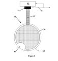
- a dormant failure of the ball valve 34 can take the form of a damaged portion 48 of the valve member 38, such as a piece that has broken off or disintegrated from an edge of the valve member 38. This has the effect of changing the mass of the valve member 38 and therefore changing its response time in relation to the undamaged valve member 38 shown in Figure 2 .
- the nominal response 50 of the ball valve 34 to a step input signal from the controller/actuator 40 is shown in Figure 4 .
- the graph plots the angular displacement measured by the position sensor 44 against time.
- the nominal step response 50 typically exhibits an overshoot peak 52 and then relatively quickly levels 54 to the demanded angular displacement.
- the nominal step response 50 can be generated as a calibration step response 50 for each valve 34 or type of valve 34. Subsequently, the step response of the valve 34 can be plotted in-use and compared to the nominal step response 50 to ascertain whether the valve response is within acceptable margins of the nominal step response 50 or whether it is outside those acceptable margins indicating failure.
- the nominal frequency response 56 can be derived from the nominal step response 50 and plotted as shown in Figure 5 .
- This graph has logarithmic frequency on the abscissa and magnitude on the ordinate.
- the nominal frequency response 56 is initially level, exhibits a slight peak and then a decrease at an approximately constant gradient.
- the relationship between the response shape, Kp and I is different.
- An exemplary in-use step response 58 is also shown in Figure 4 for a ball valve 34 that is damaged, for example by removal of a portion 48 as shown in and described with respect to Figure 2 .
- the valve 34 is damaged but not broken, so that it responds to the step input but differently to the calibration response 50.
- the in-use step response 58 will be flat and the broken status will be immediately apparent.
- the damaged valve member 38 is lighter than the equivalent undamaged valve member 38 so that its inertia is lower. This means that the initial gradient of the in-use step response 58 is larger so that the overshoot peak 60 of the response 58 occurs earlier but is smaller.
- different controllers and valve dynamics will result in different changes in initial gradient and peak position. Nevertheless, there will be a recognisable difference between the calibration step response 50 and the in-use step response 58.
- the controller/actuator 40 includes processing means to derive the step responses 50, 58, initial gradients, frequency responses 56, 64, and therefore the inertia of the valve 34.
- Any of the responses 50, 58, 56, 64 may have signal processing applied thereto, for example filtering to produce a less noisy signal or gain distortion to accentuate any differences between the calibration and in-use responses.
- Any known signal processing can be used, such as applying a fast Fourier transform.
- the in-use frequency response 64 shown in Figure 5 , can be derived from the in-use step response 58. This exhibits the same level initial portion followed by a peak at a higher frequency than the calibration frequency response 56 and followed by a decrease at approximately constant gradient. This gradient is the same as that for the nominal frequency response 56 but begins at a higher frequency so that the nominal 56 and in-use 64 responses descend in parallel. Thus the in-use frequency response 64 is shifted right in comparison to the calibration frequency response 56.
- the controller/actuator 40 can be arranged to provide a test step input at a convenient point in the cycle, for example shortly after start-up of the gas turbine engine 10, and the in-use step response 58 be determined. This can be compared to the nominal step response 50 to ascertain whether there is any difference and, if there is a difference, to compare the difference to a pre-determined error margin of the calibration step response 50 to determine whether the response 58 indicates that the valve 34 has failed.
- the in-use frequency response 64 can be derived and compared to the calibration frequency response 56.
- a dedicated test step input can be scheduled and the step response 58 also checked each time the input is provided.
- the present invention provides advantages by being more reliable since it does not rely on the behaviour of connected systems, such as the prior art compressor pressure, to indicate when a valve 34 has failed.
- valve 34 has been described as a ball valve 34 the present invention applies equally to other types of valve 34, for example a linear valve.
- a different position sensor 44 may be required with different valves, for example a linear variable differential transducer (LVDT) can be used to generate the position signal 46 for a linear valve.
- LVDT linear variable differential transducer
- the change in current can be used to generate the position signal 46 and thereby indirectly to determine the inertia of the valve 34.
- a change in inertia of the valve due to a change in its weight caused by damage for example, changes its response speed. Since the back EMF (electromotive force) is proportional to the response speed of the electric actuator for the valve this alters the current profile in a measurable manner.
- the method of the present invention can be applied to any existing valve 34 that has position sensors 44 already associated with it, by simply adding the means to generate the calibration and in-use step responses 50, 58, and to derive the frequency responses 56, 64.
- Position sensors 44 are generally cheaper and lighter than the acoustic or pressure sensors required by the prior art.
- valve applications within a gas turbine engine 10 where the method and apparatus of the present invention can be applied with felicity.
- the linkage, elongate member 42, between the controller/actuator 40 and the valve 34 may be relatively long and have a complex shape.
- the present invention also has utility for variable stator vanes (VSVs) wherein at least one actuator moves the VSVs in response to a control signal.
- VSVs variable stator vanes
Landscapes
- Engineering & Computer Science (AREA)
- General Engineering & Computer Science (AREA)
- Mechanical Engineering (AREA)
- Life Sciences & Earth Sciences (AREA)
- Sustainable Development (AREA)
- Control Of Turbines (AREA)
- Indication Of The Valve Opening Or Closing Status (AREA)
- Valve-Gear Or Valve Arrangements (AREA)
Abstract
Description
- The present invention relates to a method and arrangement for detecting failure of an actuated component. It is particularly, although not exclusively, pertinent to detecting failure of valves in safety critical applications such as gas turbine engine applications.
-
US 6,976,503 discloses a method for determining leakage and failures of a dormant valve by measuring the noise generated by the fluid flow through the valve. One disadvantage of this method is that a microphone, or other acoustic transducer, is required in order to capture the noise generated by the flow. This adds cost and weight to the valve, both of which it is generally desired to minimise. Additionally, for a valve in a harsh operating environment, such as for a gas turbine engine application, such transducers may be unable to operate at the high temperatures required and so the method has limited use. -
US 2008/238,698 A discloses a method for detecting activation of a bleed valve of a gas turbine engine by sensing the presence or absence of spikes in the compressor pressure. One problem with this method is that it is only effective for a limited number of bleed valves for a gas turbine engine. Other applications cannot use the method because there is no equivalent arrangement to the compressor in which to measure the pressure. This includes valves for other applications in a gas turbine engine, such as the flow control valve of a turbine tip clearance system or for turbine case cooling or the valve for a switched secondary air system. - Another disadvantage of this method is that it relies on the valve failure causing an effect on a different system component's dynamic behaviour, namely the compressor behaviour. This means that a valve failure may be spuriously detected if the compressor is affected by some other disturbance that is unrelated to the bleed valve failure.
- The present invention seeks to provide a method and arrangement for detecting failure of an actuated component that seeks to address the aforementioned problems.
- Accordingly a first aspect of the present invention provides a method of detecting failure of an actuated component, the method comprising determining a calibration step response for an actuated component, determining an in-use step response for the actuated component, determining any difference between the calibration and in-use step responses, and comparing the any difference to a pre-determined threshold indicating failure of the actuated component. This has the advantage of indicating failure of the actuated component without reference to any other system component, thereby reducing the likelihood of a spurious failure being registered.
- The any difference may comprise a shift in the resonant frequency of the step responses.
- A second aspect provides a method of detecting failure of an actuated component, the method comprising determining a calibration step response for an actuated component, determining an in-use step response for the actuated component, deriving a calibration frequency response from the calibration step response, deriving an in-use frequency response from the in-use step response, determining any difference between the calibration and in-use frequency responses, and comparing the any difference to a pre-determined threshold indicating failure of the actuated component. This is beneficial where there is a clearer difference between the frequency responses than the step responses.
- The any difference may comprise a shift in the frequency responses.
- In either of the first or second aspects there may be signal processing applied to the calibration and in-use responses. The signal processing may comprise applying a fast Fourier transform. Advantageously this removes noise from the responses.
- The actuated component may be a valve.
- The method may be implemented via software. The software may be integrated with control software for the actuation of the actuated component.
- A third aspect of the present invention provides a failure detection arrangement for an actuated component comprising means to generate a calibration step response for the actuated component, means to generate an in-use step response for the actuated component, and processing means to determine a change in the inertia of the actuated component, the change indicating failure of the actuated component. This has the advantage of indicating failure of the actuated component without reference to any other system component, thereby reducing the likelihood of a spurious failure being registered. Additionally, the generation means and the processing means may be implemented in software meaning no extra components are required thereby reducing weight compared to prior art arrangements.
- The actuated component may comprise a valve, particularly a ball valve or a linear valve.
- The processing means may comprise determining at least one of the initial gradient and the resonant frequency of the step response and deriving the inertia therefrom.
- A fourth aspect provides a gas turbine engine comprising an arrangement according to the third aspect.
- A fifth aspect provides a gas turbine engine incorporating a method according to the first or second aspect.
- The present invention will be more fully described by way of example with reference to the accompanying drawings, in which:
-
Figure 1 is a sectional side view of a gas turbine engine; -
Figure 2 is a schematic section of a ball valve to which the present invention may be applied; -
Figure 3 is a schematic section of the ball valve ofFigure 2 and shows a failed valve; -
Figure 4 is a graph of a step response produced in accordance with the method of the present invention; and -
Figure 5 is a graph of a frequency response derived in accordance with the method of the present invention. - A
gas turbine engine 10 is shown inFigure 1 and comprises anair intake 12 and apropulsive fan 14 that generates two airflows A and B. Thegas turbine engine 10 comprises, in axial flow A, anintermediate pressure compressor 16, ahigh pressure compressor 18, acombustor 20, ahigh pressure turbine 22, anintermediate pressure turbine 24, alow pressure turbine 26 and anexhaust nozzle 28. Anacelle 30 surrounds thegas turbine engine 10 and defines, in axial flow B, abypass duct 32. - Valves are used throughout the
engine 10 to control flows, for example bleed valves selectively permit air to bleed from thecompressors bypass duct 32; turbine tip clearance and case cooling flow valves act to deliver compressor air to one of the turbine shrouds; and anti-ice valves selectively permit warmed air to flow to thenacelle 30 around thepropulsive fan 14 to reduce or remove ice build-up. Although the method and arrangement of the present invention are described with respect to a valve for a gas turbine engine application, the skilled reader will understand that this is exemplary and non-limiting to the invention as defined in the claims. - An exemplary embodiment of the present invention is described with respect to
Figure 2 to Figure 5 . Aball valve 34 comprises aspherical housing 36 in which is located avalve member 38 in the form of a flat disc or flap. Alternatively thevalve member 38 may be a different shape as required by the application. Thevalve 34 comprises a flow inlet and a flow outlet (not shown). Fluid can pass from the inlet to the outlet in one configuration of thevalve 34 and is obstructed in another configuration of thevalve 34. - A controller/
actuator 40, having the functions of controller and of actuator, generates appropriate signals to actuate thevalve member 38 to rotate within thehousing 36 to open or close theball valve 34. An elongate member orlinkage 42 connects between thevalve member 38 and the controller/actuator 40. Coupled to theelongate member 42 is aposition sensor 44, such as a rotary variable differential transformer (RVDT), that measures angular displacement of thevalve member 38 and generates asignal 46 that is proportional to the displacement detected. Theposition signal 46 is provided to the controller/actuator 40 as a feedback signal to give closed loop control of thevalve member 38. Thesignal 46 is also provided to other systems, such as the engine electronic controller. - The
ball valve 34 has an open loop dynamic response that can be approximated by a second order differential equation having the inertia and damping coefficient of the valve as constants. The closed loop control may generally take the form of a proportional plus differential loop giving a closed loop transfer function of the form:
- In
Equation 1 Kp is the proportional gain of thevalve 34, Td is the derivative gain of the controller/actuator 40, c is the damping coefficient of thevalve 34, and I is the inertia of thevalve 34. It will be apparent to the skilled reader that different controllers may be used as known in the art and that these will result in different closed loop system responses. However, for any such closed loop response parameters can be derived that are equivalent to those described herein. - As shown in
Figure 3 , a dormant failure of theball valve 34 can take the form of a damagedportion 48 of thevalve member 38, such as a piece that has broken off or disintegrated from an edge of thevalve member 38. This has the effect of changing the mass of thevalve member 38 and therefore changing its response time in relation to the undamagedvalve member 38 shown inFigure 2 . - The
nominal response 50 of theball valve 34 to a step input signal from the controller/actuator 40 is shown inFigure 4 . The graph plots the angular displacement measured by theposition sensor 44 against time. Thenominal step response 50 typically exhibits anovershoot peak 52 and then relatively quickly levels 54 to the demanded angular displacement. Thenominal step response 50 can be generated as acalibration step response 50 for eachvalve 34 or type ofvalve 34. Subsequently, the step response of thevalve 34 can be plotted in-use and compared to thenominal step response 50 to ascertain whether the valve response is within acceptable margins of thenominal step response 50 or whether it is outside those acceptable margins indicating failure. - From the transfer function,
Equation 1, can be derived the resonant, or natural, frequency of the closed loop response of thesystem 

valve 34 and therefore whether thevalve 34 has failed through damage. For example thenominal frequency response 56 can be derived from thenominal step response 50 and plotted as shown inFigure 5 . - This graph has logarithmic frequency on the abscissa and magnitude on the ordinate. The
nominal frequency response 56 is initially level, exhibits a slight peak and then a decrease at an approximately constant gradient. Where there is an alternative closed loop response, due to the use of a different controller regime, the relationship between the response shape, Kp and I is different. - An exemplary in-
use step response 58 is also shown inFigure 4 for aball valve 34 that is damaged, for example by removal of aportion 48 as shown in and described with respect toFigure 2 . Thevalve 34 is damaged but not broken, so that it responds to the step input but differently to thecalibration response 50. Clearly where thevalve 34 is damaged to the extent that it does not move when commanded, the in-use step response 58 will be flat and the broken status will be immediately apparent. The damagedvalve member 38 is lighter than the equivalentundamaged valve member 38 so that its inertia is lower. This means that the initial gradient of the in-use step response 58 is larger so that theovershoot peak 60 of theresponse 58 occurs earlier but is smaller. As will be apparent to those skilled in the art, different controllers and valve dynamics will result in different changes in initial gradient and peak position. Nevertheless, there will be a recognisable difference between thecalibration step response 50 and the in-use step response 58. - The controller/
actuator 40 includes processing means to derive thestep responses frequency responses valve 34. Any of theresponses - The in-
use frequency response 64, shown inFigure 5 , can be derived from the in-use step response 58. This exhibits the same level initial portion followed by a peak at a higher frequency than thecalibration frequency response 56 and followed by a decrease at approximately constant gradient. This gradient is the same as that for thenominal frequency response 56 but begins at a higher frequency so that the nominal 56 and in-use 64 responses descend in parallel. Thus the in-use frequency response 64 is shifted right in comparison to thecalibration frequency response 56. - This means that it is apparent from comparison of the
step responses frequency responses valve 34 is damaged or, indeed, where it is inoperative. In a typical cyclic application, such as avalve 34 in a gas turbine engine application, the controller/actuator 40 can be arranged to provide a test step input at a convenient point in the cycle, for example shortly after start-up of thegas turbine engine 10, and the in-use step response 58 be determined. This can be compared to thenominal step response 50 to ascertain whether there is any difference and, if there is a difference, to compare the difference to a pre-determined error margin of thecalibration step response 50 to determine whether theresponse 58 indicates that thevalve 34 has failed. Alternatively or additionally the in-use frequency response 64 can be derived and compared to thecalibration frequency response 56. - It may be beneficial to adjust the gains for the test step input, for example increasing Kp or decreasing Td, so that the frequency shift and / or step response shift are more apparent where the
valve 34 is damaged. - Although it may be convenient to schedule a dedicated test step input for many applications, in other applications it may be simpler to test the
step response 58 every time such an input is provided. In still other applications a dedicated test step input can be scheduled and thestep response 58 also checked each time the input is provided. - Where pressure transducers, microphones or other prior sensors are replaced by the present invention there are significant cost and weight savings. The present invention also provides advantages by being more reliable since it does not rely on the behaviour of connected systems, such as the prior art compressor pressure, to indicate when a
valve 34 has failed. - Although the
valve 34 has been described as aball valve 34 the present invention applies equally to other types ofvalve 34, for example a linear valve. Adifferent position sensor 44 may be required with different valves, for example a linear variable differential transducer (LVDT) can be used to generate theposition signal 46 for a linear valve. Where electrical actuation of thevalve member 38 is used, the change in current can be used to generate theposition signal 46 and thereby indirectly to determine the inertia of thevalve 34. A change in inertia of the valve, due to a change in its weight caused by damage for example, changes its response speed. Since the back EMF (electromotive force) is proportional to the response speed of the electric actuator for the valve this alters the current profile in a measurable manner. - The method of the present invention can be applied to any existing
valve 34 that hasposition sensors 44 already associated with it, by simply adding the means to generate the calibration and in-use step responses frequency responses valves 34 withoutposition sensors 44 these can be added in order to derive the advantages of the present invention.Position sensors 44 are generally cheaper and lighter than the acoustic or pressure sensors required by the prior art. - There are many valve applications within a
gas turbine engine 10 where the method and apparatus of the present invention can be applied with felicity. For example, in connection with a valve for turbine case cooling, rotor tip clearance control, fuel regulator valves, and bleed valves with continuous movement. For some of these applications the linkage,elongate member 42, between the controller/actuator 40 and thevalve 34 may be relatively long and have a complex shape. The present invention also has utility for variable stator vanes (VSVs) wherein at least one actuator moves the VSVs in response to a control signal. The step and frequency responses can be derived in the same manner as for valve applications of the invention. - The method and arrangement of the present invention have been described in relation to applications for
gas turbine engines 10. However, it can be used with equal felicity in other technical fields that require detection of failures ofdormant valves 34 or other actuated components, for example the aircraft, marine, automotive, nuclear, energy and power industries.
Claims (13)
- A method of detecting failure of an actuated component (34), the method comprising• determining a calibration step response (50) for an actuated component (34),• calculating a calibration inertia (I) from the calibration step response (50);• determining an in-use step response (58) for the actuated component (34),• calculating an in-use inertia (I) from the in-use step response (58);• calculating a change in the inertia (I) between the calibration inertia (I) and the in-use inertia (I), and• automatically comparing the change in inertia (I) to a pre-determined threshold indicating failure of the actuated component (34).
- A method as claimed in claim 1 further comprising applying signal processing to the calibration (50) and in-use step responses (58).
- A method as claimed in claim 2 wherein applying signal processing comprises applying a fast Fourier transform.
- A method as claimed in any preceding claim wherein the calibration inertia (I) is calculated from at least one of the initial gradient and the resonant frequency (ω0) of the calibration step response (50) and the in-use inertia (I) is calculated from at least one of the initial gradient and the resonant frequency (ω0) of the in-use step response (58).
- A method as claimed in any preceding claim further comprising• deriving a calibration frequency response (56) from the calibration step response (50), and• deriving an in-use frequency response (64) from the in-use step response (58),
wherein the calibration inertia (I) is calculated from the calibration frequency response (56) and the in-use inertia (I) is calculated from the in-use frequency response (64). - A method as claimed in claim 5 further comprising applying signal processing to the calibration (56) and in-use frequency responses (64).
- A method as claimed in claim 6 wherein applying signal processing comprises applying a fast Fourier transform.
- A method as claimed in any preceding claim wherein the actuated component (34) comprises a valve.
- A failure detection arrangement for an actuated component (34) comprising• apparatus that generates a calibration step response (50) for the actuated component (34),• apparatus that generates an in-use step response (58) for the actuated component (34), and• a processor thata) calculates a calibration inertia (I) for the actuated component (34) from the calibration step response (50),b) calculates an in-use inertia (I) for the actuated component (34) from the in-use step response (58), andc) determines a change in the inertia (I) of the actuated component (34), the change indicating failure of the actuated component (34).
- An arrangement as claimed in claim 9 wherein the actuated component (34) comprises a valve.
- An arrangement as claimed in claim 9 or 10 wherein the actuated component (34) comprises a ball valve or a linear valve.
- An arrangement as claimed in any of claims 9 to 11 wherein the processor calculates the calibration inertia (I) and the in-use inertia (I) from at least one of the initial gradient and the resonant frequency (ω0) of the step response (50, 58).
- A gas turbine engine (10) comprising an arrangement as claimed in any of claims 9 to 12.
Applications Claiming Priority (1)
| Application Number | Priority Date | Filing Date | Title |
|---|---|---|---|
| GBGB0911597.3A GB0911597D0 (en) | 2009-07-06 | 2009-07-06 | Valve failure detection |
Publications (3)
| Publication Number | Publication Date |
|---|---|
| EP2273168A2 true EP2273168A2 (en) | 2011-01-12 |
| EP2273168A3 EP2273168A3 (en) | 2014-07-30 |
| EP2273168B1 EP2273168B1 (en) | 2017-08-23 |
Family
ID=41008721
Family Applications (1)
| Application Number | Title | Priority Date | Filing Date |
|---|---|---|---|
| EP10167135.2A Not-in-force EP2273168B1 (en) | 2009-07-06 | 2010-06-24 | Valve failure detection |
Country Status (3)
| Country | Link |
|---|---|
| US (1) | US8191409B2 (en) |
| EP (1) | EP2273168B1 (en) |
| GB (1) | GB0911597D0 (en) |
Cited By (4)
| Publication number | Priority date | Publication date | Assignee | Title |
|---|---|---|---|---|
| GB2480423A (en) * | 2010-03-15 | 2011-11-23 | Jena Rotary Technolgy Ltd | Valve system |
| GB2491045A (en) * | 2011-05-20 | 2012-11-21 | Romax Technology Ltd | Determining damage to, or remaining useful life of, rotating machinery eg drive trains, gearboxes and generators of wind and water turbines |
| EP2829473A1 (en) * | 2013-07-24 | 2015-01-28 | Air China Limited | Method and apparatus for monitoring a wing anti-icing valve |
| EP3012439A1 (en) * | 2014-10-22 | 2016-04-27 | Rolls-Royce plc | Method to determine inertia in a shaft system |
Families Citing this family (12)
| Publication number | Priority date | Publication date | Assignee | Title |
|---|---|---|---|---|
| US8701703B2 (en) | 2010-08-09 | 2014-04-22 | Sensus Usa Inc. | Method and apparatus for controlling gas flow via a gas shut-off valve assembly |
| US10065728B2 (en) | 2011-06-30 | 2018-09-04 | Parker-Hannifin Corporation | Horizontal stabilizer trim actuator failure detection system and method using position sensors |
| US20130283762A1 (en) * | 2012-04-27 | 2013-10-31 | General Electric Company | Rotary vane actuator operated air valves |
| WO2013183059A1 (en) * | 2012-06-07 | 2013-12-12 | Eltav Wireless Monitoring Ltd. | Device and system for predicting failures of actuated valves |
| US8967196B2 (en) * | 2012-06-29 | 2015-03-03 | Solar Turbines Incorporated | Valve assembly with valve position indicator |
| US9453693B2 (en) * | 2012-07-10 | 2016-09-27 | Maxi-Therme Inc. | Method of controlling the saturation level of a generated gaseous state fluid |
| CA2891071C (en) * | 2012-11-09 | 2022-04-26 | Snecma | Method and system for determining the flow rate of air collected from an aircraft engine |
| US9261026B2 (en) * | 2013-06-27 | 2016-02-16 | Pratt & Whitney Canada Corp. | System and method for conditioning noisy signals |
| US10626803B2 (en) * | 2015-10-22 | 2020-04-21 | United Technologies Corporation | Apparatus and method for controlling and monitoring an electro-hydraulic servovalve |
| US10933978B2 (en) | 2017-01-10 | 2021-03-02 | Parker-Hannifin Corporation | Moving end electronic detection of secondary load path engagement of aircraft flight control actuator |
| EP3517185B1 (en) * | 2018-01-29 | 2026-07-29 | Marioff Corporation OY | Valve assembly |
| US12071904B2 (en) | 2022-10-19 | 2024-08-27 | Mitsubishi Power Aero LLC | Systems and methods for bleed valve testing in gas turbine engines |
Citations (2)
| Publication number | Priority date | Publication date | Assignee | Title |
|---|---|---|---|---|
| US6976503B2 (en) | 2002-04-26 | 2005-12-20 | Siemens Aktiengesellschaft | Diagnostic system and method for a valve |
| US20080238698A1 (en) | 2006-09-29 | 2008-10-02 | Rolls-Royce Plc | Activation sensing |
Family Cites Families (17)
| Publication number | Priority date | Publication date | Assignee | Title |
|---|---|---|---|---|
| US3341849A (en) | 1966-01-26 | 1967-09-12 | Bendix Corp | Self-calibrating, self-testing radio altimeter |
| US4816987A (en) * | 1985-06-28 | 1989-03-28 | Electric Power Research Institute, Inc. | Microprocessor-based control and diagnostic system for motor operated valves |
| US5072781A (en) | 1990-07-30 | 1991-12-17 | United Technologies Corporation | Temperature control system |
| FR2673673A1 (en) | 1991-03-08 | 1992-09-11 | Elf Aquitaine | METHOD FOR VERIFYING THE PROPER FUNCTIONING OF A SAFETY VALVE OF AN OIL WELL. |
| US5365787A (en) | 1991-10-02 | 1994-11-22 | Monitoring Technology Corp. | Noninvasive method and apparatus for determining resonance information for rotating machinery components and for anticipating component failure from changes therein |
| DE69515096T2 (en) * | 1994-10-18 | 2000-07-20 | Neles Controls Oy, Helsinki | Method and device for determining a fault in a control valve arrangement in a control loop |
| JP3254624B2 (en) | 1996-05-31 | 2002-02-12 | 株式会社山武 | Stick-slip detection method and detection device |
| DE19643297C1 (en) | 1996-10-21 | 1998-03-12 | Samson Ag | In-service monitoring method for servo equipment |
| JP2000214052A (en) | 1999-01-28 | 2000-08-04 | Nichiha Corp | Abnormal sound detection system and recording medium |
| DE19924377B4 (en) * | 1999-05-27 | 2004-12-02 | Siemens Ag | Diagnostic system for a valve actuated by a positioner via a drive |
| DE19947129A1 (en) * | 1999-09-30 | 2001-04-05 | Siemens Ag | Diagnosis system, especially for control |
| US6837226B2 (en) | 2001-01-31 | 2005-01-04 | Cummins, Inc. | System for diagnosing EGR valve, actuator and sensor related failure conditions |
| US7384876B2 (en) | 2002-12-20 | 2008-06-10 | Tokyo Electron Limited | Method and apparatus for determining consumable lifetime |
| JP3970829B2 (en) * | 2003-10-10 | 2007-09-05 | 三菱電機株式会社 | Servo control device |
| US7274995B2 (en) | 2003-11-19 | 2007-09-25 | Honeywell International Inc. | Apparatus and method for identifying possible defect indicators for a valve |
| GB0411447D0 (en) | 2004-05-21 | 2004-06-23 | Navitas Uk Ltd | Valve monitoring system |
| JP4782766B2 (en) | 2007-12-27 | 2011-09-28 | オークマ株式会社 | Machine diagnostic method and apparatus |
-
2009
- 2009-07-06 GB GBGB0911597.3A patent/GB0911597D0/en not_active Ceased
-
2010
- 2010-06-24 US US12/822,391 patent/US8191409B2/en active Active
- 2010-06-24 EP EP10167135.2A patent/EP2273168B1/en not_active Not-in-force
Patent Citations (2)
| Publication number | Priority date | Publication date | Assignee | Title |
|---|---|---|---|---|
| US6976503B2 (en) | 2002-04-26 | 2005-12-20 | Siemens Aktiengesellschaft | Diagnostic system and method for a valve |
| US20080238698A1 (en) | 2006-09-29 | 2008-10-02 | Rolls-Royce Plc | Activation sensing |
Cited By (12)
| Publication number | Priority date | Publication date | Assignee | Title |
|---|---|---|---|---|
| GB2480423A (en) * | 2010-03-15 | 2011-11-23 | Jena Rotary Technolgy Ltd | Valve system |
| GB2491045A (en) * | 2011-05-20 | 2012-11-21 | Romax Technology Ltd | Determining damage to, or remaining useful life of, rotating machinery eg drive trains, gearboxes and generators of wind and water turbines |
| GB2491045B (en) * | 2011-05-20 | 2013-10-30 | Romax Technology Ltd | Determining damage and remaining useful life of rotating machinery including drive trains, gearboxes, and generators |
| US10466138B2 (en) | 2011-05-20 | 2019-11-05 | Andy Poon | Determining remaining useful life of rotating machinery including drive trains, gearboxes, and generators |
| US10527520B2 (en) | 2011-05-20 | 2020-01-07 | Insight Analytics Solutions Holdings Limited | Operating wind motors and determining their remaining useful life |
| EP2829473A1 (en) * | 2013-07-24 | 2015-01-28 | Air China Limited | Method and apparatus for monitoring a wing anti-icing valve |
| JP2015024810A (en) * | 2013-07-24 | 2015-02-05 | エア チャイナ リミテッド | System and method for monitoring aircraft wing anti-icing valve |
| US9446853B2 (en) * | 2013-07-24 | 2016-09-20 | Air China Limited | Method and apparatus for monitoring the wing anti-icing valve |
| AU2014206167B2 (en) * | 2013-07-24 | 2016-11-17 | Air China Limited | Method and apparatus for monitoring the wing anti-icing valve |
| TWI625275B (en) * | 2013-07-24 | 2018-06-01 | Monitoring system and method for aircraft wing anti-icing valve | |
| EP3012439A1 (en) * | 2014-10-22 | 2016-04-27 | Rolls-Royce plc | Method to determine inertia in a shaft system |
| US9435683B2 (en) | 2014-10-22 | 2016-09-06 | Rolls-Royce Plc | Method to determine inertia in a shaft system |
Also Published As
| Publication number | Publication date |
|---|---|
| EP2273168B1 (en) | 2017-08-23 |
| GB0911597D0 (en) | 2009-08-12 |
| US8191409B2 (en) | 2012-06-05 |
| EP2273168A3 (en) | 2014-07-30 |
| US20110000287A1 (en) | 2011-01-06 |
Similar Documents
| Publication | Publication Date | Title |
|---|---|---|
| EP2273168B1 (en) | Valve failure detection | |
| US9506401B2 (en) | Method of detecting shaft break | |
| EP3287609B1 (en) | Turbofan shaft break detection system and method | |
| US9404385B2 (en) | Shaft break detection | |
| CN103180577B (en) | The method controlling turbine | |
| CN102331341B (en) | For monitoring the system and method for the health status of airfoil | |
| EP3171004A1 (en) | Method and system for improving parameter measurement | |
| JP5898865B2 (en) | System and method for monitoring airfoil health | |
| US9250153B2 (en) | Methods and systems for monitoring health of blades | |
| JP2002180851A (en) | Method and device for monitoring operation of gas turbine engine | |
| EP2199680A1 (en) | Combuster rumble | |
| EP3409926B1 (en) | Method and system for detecting a high temperature condition of a gas turbine | |
| CN111720218B (en) | Signal response monitoring for turbine engines | |
| EP2461010B1 (en) | Active fan flutter control system and method | |
| EP0777828B1 (en) | Compressor stall avoidance | |
| EP2458179B1 (en) | Method of monitoring an electronic engine control (EEC) to detect fuel screen clogging | |
| EP3106649A1 (en) | Aircraft gas turbine propulsion engine control without aircraft total air temperature sensors | |
| US11168635B2 (en) | Methods and systems for assessing engine health | |
| GB2581467A (en) | Combined system controller | |
| JP6280354B2 (en) | System and method for monitoring airfoil health | |
| JP2010048172A (en) | Control device for gas turbine engine |
Legal Events
| Date | Code | Title | Description |
|---|---|---|---|
| PUAI | Public reference made under article 153(3) epc to a published international application that has entered the european phase |
Free format text: ORIGINAL CODE: 0009012 |
|
| AK | Designated contracting states |
Kind code of ref document: A2 Designated state(s): AL AT BE BG CH CY CZ DE DK EE ES FI FR GB GR HR HU IE IS IT LI LT LU LV MC MK MT NL NO PL PT RO SE SI SK SM TR |
|
| AX | Request for extension of the european patent |
Extension state: BA ME RS |
|
| RIN1 | Information on inventor provided before grant (corrected) |
Inventor name: BACIC, MARKO |
|
| PUAL | Search report despatched |
Free format text: ORIGINAL CODE: 0009013 |
|
| AK | Designated contracting states |
Kind code of ref document: A3 Designated state(s): AL AT BE BG CH CY CZ DE DK EE ES FI FR GB GR HR HU IE IS IT LI LT LU LV MC MK MT NL NO PL PT RO SE SI SK SM TR |
|
| AX | Request for extension of the european patent |
Extension state: BA ME RS |
|
| RIC1 | Information provided on ipc code assigned before grant |
Ipc: F16K 37/00 20060101AFI20140625BHEP |
|
| 17P | Request for examination filed |
Effective date: 20150126 |
|
| RBV | Designated contracting states (corrected) |
Designated state(s): AL AT BE BG CH CY CZ DE DK EE ES FI FR GB GR HR HU IE IS IT LI LT LU LV MC MK MT NL NO PL PT RO SE SI SK SM TR |
|
| RAP1 | Party data changed (applicant data changed or rights of an application transferred) |
Owner name: ROLLS-ROYCE PLC |
|
| REG | Reference to a national code |
Ref country code: DE Ref legal event code: R079 Ref document number: 602010044560 Country of ref document: DE Free format text: PREVIOUS MAIN CLASS: F16K0037000000 Ipc: F04D0027000000 |
|
| RIC1 | Information provided on ipc code assigned before grant |
Ipc: F04D 27/02 20060101ALI20170302BHEP Ipc: F04D 27/00 20060101AFI20170302BHEP Ipc: F16K 37/00 20060101ALI20170302BHEP |
|
| GRAP | Despatch of communication of intention to grant a patent |
Free format text: ORIGINAL CODE: EPIDOSNIGR1 |
|
| STAA | Information on the status of an ep patent application or granted ep patent |
Free format text: STATUS: GRANT OF PATENT IS INTENDED |
|
| INTG | Intention to grant announced |
Effective date: 20170419 |
|
| GRAS | Grant fee paid |
Free format text: ORIGINAL CODE: EPIDOSNIGR3 |
|
| GRAA | (expected) grant |
Free format text: ORIGINAL CODE: 0009210 |
|
| STAA | Information on the status of an ep patent application or granted ep patent |
Free format text: STATUS: THE PATENT HAS BEEN GRANTED |
|
| AK | Designated contracting states |
Kind code of ref document: B1 Designated state(s): AL AT BE BG CH CY CZ DE DK EE ES FI FR GB GR HR HU IE IS IT LI LT LU LV MC MK MT NL NO PL PT RO SE SI SK SM TR |
|
| REG | Reference to a national code |
Ref country code: GB Ref legal event code: FG4D |
|
| REG | Reference to a national code |
Ref country code: CH Ref legal event code: EP |
|
| REG | Reference to a national code |
Ref country code: AT Ref legal event code: REF Ref document number: 921655 Country of ref document: AT Kind code of ref document: T Effective date: 20170915 |
|
| REG | Reference to a national code |
Ref country code: IE Ref legal event code: FG4D |
|
| REG | Reference to a national code |
Ref country code: DE Ref legal event code: R096 Ref document number: 602010044560 Country of ref document: DE |
|
| REG | Reference to a national code |
Ref country code: NL Ref legal event code: MP Effective date: 20170823 |
|
| REG | Reference to a national code |
Ref country code: LT Ref legal event code: MG4D |
|
| REG | Reference to a national code |
Ref country code: AT Ref legal event code: MK05 Ref document number: 921655 Country of ref document: AT Kind code of ref document: T Effective date: 20170823 |
|
| PG25 | Lapsed in a contracting state [announced via postgrant information from national office to epo] |
Ref country code: LT Free format text: LAPSE BECAUSE OF FAILURE TO SUBMIT A TRANSLATION OF THE DESCRIPTION OR TO PAY THE FEE WITHIN THE PRESCRIBED TIME-LIMIT Effective date: 20170823 Ref country code: AT Free format text: LAPSE BECAUSE OF FAILURE TO SUBMIT A TRANSLATION OF THE DESCRIPTION OR TO PAY THE FEE WITHIN THE PRESCRIBED TIME-LIMIT Effective date: 20170823 Ref country code: NL Free format text: LAPSE BECAUSE OF FAILURE TO SUBMIT A TRANSLATION OF THE DESCRIPTION OR TO PAY THE FEE WITHIN THE PRESCRIBED TIME-LIMIT Effective date: 20170823 Ref country code: HR Free format text: LAPSE BECAUSE OF FAILURE TO SUBMIT A TRANSLATION OF THE DESCRIPTION OR TO PAY THE FEE WITHIN THE PRESCRIBED TIME-LIMIT Effective date: 20170823 Ref country code: SE Free format text: LAPSE BECAUSE OF FAILURE TO SUBMIT A TRANSLATION OF THE DESCRIPTION OR TO PAY THE FEE WITHIN THE PRESCRIBED TIME-LIMIT Effective date: 20170823 Ref country code: NO Free format text: LAPSE BECAUSE OF FAILURE TO SUBMIT A TRANSLATION OF THE DESCRIPTION OR TO PAY THE FEE WITHIN THE PRESCRIBED TIME-LIMIT Effective date: 20171123 Ref country code: FI Free format text: LAPSE BECAUSE OF FAILURE TO SUBMIT A TRANSLATION OF THE DESCRIPTION OR TO PAY THE FEE WITHIN THE PRESCRIBED TIME-LIMIT Effective date: 20170823 |
|
| PG25 | Lapsed in a contracting state [announced via postgrant information from national office to epo] |
Ref country code: LV Free format text: LAPSE BECAUSE OF FAILURE TO SUBMIT A TRANSLATION OF THE DESCRIPTION OR TO PAY THE FEE WITHIN THE PRESCRIBED TIME-LIMIT Effective date: 20170823 Ref country code: IS Free format text: LAPSE BECAUSE OF FAILURE TO SUBMIT A TRANSLATION OF THE DESCRIPTION OR TO PAY THE FEE WITHIN THE PRESCRIBED TIME-LIMIT Effective date: 20171223 Ref country code: PL Free format text: LAPSE BECAUSE OF FAILURE TO SUBMIT A TRANSLATION OF THE DESCRIPTION OR TO PAY THE FEE WITHIN THE PRESCRIBED TIME-LIMIT Effective date: 20170823 Ref country code: GR Free format text: LAPSE BECAUSE OF FAILURE TO SUBMIT A TRANSLATION OF THE DESCRIPTION OR TO PAY THE FEE WITHIN THE PRESCRIBED TIME-LIMIT Effective date: 20171124 Ref country code: BG Free format text: LAPSE BECAUSE OF FAILURE TO SUBMIT A TRANSLATION OF THE DESCRIPTION OR TO PAY THE FEE WITHIN THE PRESCRIBED TIME-LIMIT Effective date: 20171123 Ref country code: ES Free format text: LAPSE BECAUSE OF FAILURE TO SUBMIT A TRANSLATION OF THE DESCRIPTION OR TO PAY THE FEE WITHIN THE PRESCRIBED TIME-LIMIT Effective date: 20170823 |
|
| PG25 | Lapsed in a contracting state [announced via postgrant information from national office to epo] |
Ref country code: CZ Free format text: LAPSE BECAUSE OF FAILURE TO SUBMIT A TRANSLATION OF THE DESCRIPTION OR TO PAY THE FEE WITHIN THE PRESCRIBED TIME-LIMIT Effective date: 20170823 Ref country code: RO Free format text: LAPSE BECAUSE OF FAILURE TO SUBMIT A TRANSLATION OF THE DESCRIPTION OR TO PAY THE FEE WITHIN THE PRESCRIBED TIME-LIMIT Effective date: 20170823 Ref country code: DK Free format text: LAPSE BECAUSE OF FAILURE TO SUBMIT A TRANSLATION OF THE DESCRIPTION OR TO PAY THE FEE WITHIN THE PRESCRIBED TIME-LIMIT Effective date: 20170823 |
|
| REG | Reference to a national code |
Ref country code: DE Ref legal event code: R097 Ref document number: 602010044560 Country of ref document: DE |
|
| PG25 | Lapsed in a contracting state [announced via postgrant information from national office to epo] |
Ref country code: SM Free format text: LAPSE BECAUSE OF FAILURE TO SUBMIT A TRANSLATION OF THE DESCRIPTION OR TO PAY THE FEE WITHIN THE PRESCRIBED TIME-LIMIT Effective date: 20170823 Ref country code: IT Free format text: LAPSE BECAUSE OF FAILURE TO SUBMIT A TRANSLATION OF THE DESCRIPTION OR TO PAY THE FEE WITHIN THE PRESCRIBED TIME-LIMIT Effective date: 20170823 Ref country code: EE Free format text: LAPSE BECAUSE OF FAILURE TO SUBMIT A TRANSLATION OF THE DESCRIPTION OR TO PAY THE FEE WITHIN THE PRESCRIBED TIME-LIMIT Effective date: 20170823 Ref country code: SK Free format text: LAPSE BECAUSE OF FAILURE TO SUBMIT A TRANSLATION OF THE DESCRIPTION OR TO PAY THE FEE WITHIN THE PRESCRIBED TIME-LIMIT Effective date: 20170823 |
|
| REG | Reference to a national code |
Ref country code: FR Ref legal event code: PLFP Year of fee payment: 9 |
|
| PLBE | No opposition filed within time limit |
Free format text: ORIGINAL CODE: 0009261 |
|
| STAA | Information on the status of an ep patent application or granted ep patent |
Free format text: STATUS: NO OPPOSITION FILED WITHIN TIME LIMIT |
|
| 26N | No opposition filed |
Effective date: 20180524 |
|
| PG25 | Lapsed in a contracting state [announced via postgrant information from national office to epo] |
Ref country code: SI Free format text: LAPSE BECAUSE OF FAILURE TO SUBMIT A TRANSLATION OF THE DESCRIPTION OR TO PAY THE FEE WITHIN THE PRESCRIBED TIME-LIMIT Effective date: 20170823 |
|
| REG | Reference to a national code |
Ref country code: CH Ref legal event code: PL |
|
| REG | Reference to a national code |
Ref country code: BE Ref legal event code: MM Effective date: 20180630 |
|
| REG | Reference to a national code |
Ref country code: IE Ref legal event code: MM4A |
|
| PG25 | Lapsed in a contracting state [announced via postgrant information from national office to epo] |
Ref country code: LU Free format text: LAPSE BECAUSE OF NON-PAYMENT OF DUE FEES Effective date: 20180624 Ref country code: MC Free format text: LAPSE BECAUSE OF FAILURE TO SUBMIT A TRANSLATION OF THE DESCRIPTION OR TO PAY THE FEE WITHIN THE PRESCRIBED TIME-LIMIT Effective date: 20170823 |
|
| PG25 | Lapsed in a contracting state [announced via postgrant information from national office to epo] |
Ref country code: LI Free format text: LAPSE BECAUSE OF NON-PAYMENT OF DUE FEES Effective date: 20180630 Ref country code: CH Free format text: LAPSE BECAUSE OF NON-PAYMENT OF DUE FEES Effective date: 20180630 Ref country code: IE Free format text: LAPSE BECAUSE OF NON-PAYMENT OF DUE FEES Effective date: 20180624 |
|
| PG25 | Lapsed in a contracting state [announced via postgrant information from national office to epo] |
Ref country code: BE Free format text: LAPSE BECAUSE OF NON-PAYMENT OF DUE FEES Effective date: 20180630 |
|
| PG25 | Lapsed in a contracting state [announced via postgrant information from national office to epo] |
Ref country code: MT Free format text: LAPSE BECAUSE OF NON-PAYMENT OF DUE FEES Effective date: 20180624 |
|
| PG25 | Lapsed in a contracting state [announced via postgrant information from national office to epo] |
Ref country code: TR Free format text: LAPSE BECAUSE OF FAILURE TO SUBMIT A TRANSLATION OF THE DESCRIPTION OR TO PAY THE FEE WITHIN THE PRESCRIBED TIME-LIMIT Effective date: 20170823 |
|
| PG25 | Lapsed in a contracting state [announced via postgrant information from national office to epo] |
Ref country code: HU Free format text: LAPSE BECAUSE OF FAILURE TO SUBMIT A TRANSLATION OF THE DESCRIPTION OR TO PAY THE FEE WITHIN THE PRESCRIBED TIME-LIMIT; INVALID AB INITIO Effective date: 20100624 Ref country code: PT Free format text: LAPSE BECAUSE OF FAILURE TO SUBMIT A TRANSLATION OF THE DESCRIPTION OR TO PAY THE FEE WITHIN THE PRESCRIBED TIME-LIMIT Effective date: 20170823 |
|
| PG25 | Lapsed in a contracting state [announced via postgrant information from national office to epo] |
Ref country code: CY Free format text: LAPSE BECAUSE OF FAILURE TO SUBMIT A TRANSLATION OF THE DESCRIPTION OR TO PAY THE FEE WITHIN THE PRESCRIBED TIME-LIMIT Effective date: 20170823 Ref country code: MK Free format text: LAPSE BECAUSE OF NON-PAYMENT OF DUE FEES Effective date: 20170823 |
|
| PG25 | Lapsed in a contracting state [announced via postgrant information from national office to epo] |
Ref country code: AL Free format text: LAPSE BECAUSE OF FAILURE TO SUBMIT A TRANSLATION OF THE DESCRIPTION OR TO PAY THE FEE WITHIN THE PRESCRIBED TIME-LIMIT Effective date: 20170823 |
|
| P01 | Opt-out of the competence of the unified patent court (upc) registered |
Effective date: 20230528 |
|
| PGFP | Annual fee paid to national office [announced via postgrant information from national office to epo] |
Ref country code: FR Payment date: 20230622 Year of fee payment: 14 Ref country code: DE Payment date: 20230627 Year of fee payment: 14 |
|
| PGFP | Annual fee paid to national office [announced via postgrant information from national office to epo] |
Ref country code: GB Payment date: 20230620 Year of fee payment: 14 |
|
| REG | Reference to a national code |
Ref country code: DE Ref legal event code: R119 Ref document number: 602010044560 Country of ref document: DE |
|
| GBPC | Gb: european patent ceased through non-payment of renewal fee |
Effective date: 20240624 |
|
| PG25 | Lapsed in a contracting state [announced via postgrant information from national office to epo] |
Ref country code: DE Free format text: LAPSE BECAUSE OF NON-PAYMENT OF DUE FEES Effective date: 20250101 |
|
| PG25 | Lapsed in a contracting state [announced via postgrant information from national office to epo] |
Ref country code: FR Free format text: LAPSE BECAUSE OF NON-PAYMENT OF DUE FEES Effective date: 20240630 |
|
| PG25 | Lapsed in a contracting state [announced via postgrant information from national office to epo] |
Ref country code: GB Free format text: LAPSE BECAUSE OF NON-PAYMENT OF DUE FEES Effective date: 20240624 |