EP2273043A2 - Modular device, reversible and polyvalent, of antipanic closure for mortise locks - Google Patents
Modular device, reversible and polyvalent, of antipanic closure for mortise locks Download PDFInfo
- Publication number
- EP2273043A2 EP2273043A2 EP10164977A EP10164977A EP2273043A2 EP 2273043 A2 EP2273043 A2 EP 2273043A2 EP 10164977 A EP10164977 A EP 10164977A EP 10164977 A EP10164977 A EP 10164977A EP 2273043 A2 EP2273043 A2 EP 2273043A2
- Authority
- EP
- European Patent Office
- Prior art keywords
- case
- reversible
- locking device
- cam
- door
- Prior art date
- Legal status (The legal status is an assumption and is not a legal conclusion. Google has not performed a legal analysis and makes no representation as to the accuracy of the status listed.)
- Granted
Links
Images


Classifications
-
- E—FIXED CONSTRUCTIONS
- E05—LOCKS; KEYS; WINDOW OR DOOR FITTINGS; SAFES
- E05B—LOCKS; ACCESSORIES THEREFOR; HANDCUFFS
- E05B65/00—Locks or fastenings for special use
- E05B65/10—Locks or fastenings for special use for panic or emergency doors
- E05B65/1046—Panic bars
- E05B65/106—Panic bars pivoting
- E05B65/1066—Panic bars pivoting the pivot axis being substantially parallel to the longitudinal axis of the bar
-
- E—FIXED CONSTRUCTIONS
- E05—LOCKS; KEYS; WINDOW OR DOOR FITTINGS; SAFES
- E05B—LOCKS; ACCESSORIES THEREFOR; HANDCUFFS
- E05B65/00—Locks or fastenings for special use
- E05B65/10—Locks or fastenings for special use for panic or emergency doors
- E05B65/1046—Panic bars
- E05B65/1053—Panic bars sliding towards and away form the door
-
- E—FIXED CONSTRUCTIONS
- E05—LOCKS; KEYS; WINDOW OR DOOR FITTINGS; SAFES
- E05B—LOCKS; ACCESSORIES THEREFOR; HANDCUFFS
- E05B63/00—Locks or fastenings with special structural characteristics
- E05B63/04—Locks or fastenings with special structural characteristics for alternative use on the right-hand or left-hand side of wings
- E05B63/042—Locks or fastenings with special structural characteristics for alternative use on the right-hand or left-hand side of wings constructed symmetrically
-
- E—FIXED CONSTRUCTIONS
- E05—LOCKS; KEYS; WINDOW OR DOOR FITTINGS; SAFES
- E05B—LOCKS; ACCESSORIES THEREFOR; HANDCUFFS
- E05B9/00—Lock casings or latch-mechanism casings ; Fastening locks or fasteners or parts thereof to the wing
- E05B9/08—Fastening locks or fasteners or parts thereof, e.g. the casings of latch-bolt locks or cylinder locks to the wing
Definitions
- the object of this invention is intended for application in locks mortised in the thickness of doors.
- panic bars Two types are known and frequently used in this field.
- One of them consists in a pushbar that is articulated at its ends to carry out, by means of two connecting rods, a collapsing rotation on the door; this type is known in this field by its English name, pushbar, which will be the one used hereinafter.
- the other type consists in a bar that includes an outer casing capable of linear movement perpendicular to the door; this type is known in this field by its English name, touchbar, which will be the one used hereinafter.
- panic bar pushbar and touchbar
- a main lock having a bolt or lacking one; that the main lock also has to actuate side returns located at a different height than the door; that upper and lower returns also have to be actuated from the main lock.
- each one of these options corresponds nowadays to its own and exclusive design such that manufacturers and the distribution chain of this type of product face big design, material-procurement, production, storage and distribution problems.
- this invention proposes a device of a modular and compact design that is going to allow it to be applied to the different alternatives of execution existing nowadays - described above - and particularly for mortise locks.
- the proposed device comprises a case that is fastened to a door by means of a base plate, a first-order lever that has a vertical axis of rotation in the case, and a cam with a reciprocal topography of facing surfaces that belong to the base plate and to a floor wall of the case, this cam having its virtual axis of rotation in a hollow that is reciprocal to the square shaft of a lock mortised in the thickness of the door, this hollow being in a shaft journal that is reciprocal to a bearing of the base plate, the case of which has a first vertical sidewall provided with a complementary window of the shaft hub of the connecting rod of a pushbar of a panic locking mechanism installed across the width of the inner side of the door, there being in this first sidewall at least one reciprocally wide slot of the thickness of a tongue belonging to the end swinging arm of a panic locking device actuated by means of a pushbar, the first-order lever of which has a first arm in contact with a projecting part of the shaft hub on a face thereof
- the body of the case is symmetrical in relation to the transverse and horizontal mid plane thereof; that the base plate is symmetrical in relation to its transverse and horizontal mid plane; and that the first-order lever is symmetrical in relation to its transverse and horizontal mid plane.
- the hub of the shaft of the connecting rod of the corresponding pushbar is coupled in the window of the first sidewall of the case, whereupon the second lug stays (according to the direction of rotation of the opening of the lock) behind the first arm of the first-order lever; on the other hand, since the second arm also stays behind the first lug associated with the cam, and since this cam is coupled to the square shaft of the mortise lock, it turns out that, upon the actuation of the pushbar, the second lug makes the first-order lever rotate and, in turn, the latter makes the cam rotate, dragging with it the square shaft of the mortise lock.
- the properties of the device have been explained as for a compact, modular and multipurpose design as regards its application for pushbar and touchbar panic locks alike.
- To use the reversibility property such that the same device may be used for doors opening to the left or to the right, it will suffice to invert the position of the case from top to bottom without it being necessary to do the same with the first-order lever; as for the cam and the base plate, the inversion or not of their position following the inversion of the case might not be necessary, in each case depending on the direction of rotation required for the square shaft of the mortise lock.
- a preferred embodiment of the object of the invention is depicted in the attached plans that is related to a device of modular design, specially intended for application in locks that are mortised in the thickness of doors, that is reversible and can be actuated in a multipurpose manner by the panic locks that are installed in emergency exit doors and have a main lock mechanism, provided or not with a locking bolt, and/or upper (on the lintel) and lower (on the threshold) locking points, and/or side locking points on the door frame post, and where said main lock is actuated by means of a bar that is transversally installed on the door.
- said device comprises a case (1) that is fastened to a door (2) by means of a base plate (3), a first-order lever (4) that has a vertical axis of rotation (4a) in the case (1), and a cam (5) with a reciprocal topography of facing surfaces that belong to the base plate (3) and to a floor wall (1f) of the case (1), this cam (5) having its virtual axis of rotation in a hollow (5a) that is reciprocal to the square shaft (6a) of a lock (6) mortised in the thickness of the door (2), this hollow being in a shaft journal (5c) that is reciprocal to a bearing (3a) of the base plate (3), the case (1) of which has a first vertical sidewall (1a) provided with a complementary window (1c) of the shaft hub (7b) of the connecting rod (7a) of a pushbar (7) of a panic locking mechanism installed across the width of the inner side of the door (2), there being in this first sidewall (1a) at least one reciprocally wide slot (1d) of the thickness of
- the vertical axis of rotation (4a) of the first-order lever (4) has its ends resting on seats included in the case (1) which, as can be seen in Figures 1 , 2 and 5 , are folds (1e) of the second vertical sidewall (1b) of the case (1); likewise, the following is true: that in the first sidewall (1a) two are the slots (1d) that are provided for as many other tongues (8a) of the end swinging arm (8) of a pushbar-type panic locking mechanism; that the protruding part (5b) of the cam (5) is a first lug; and that the projecting part (7c) of the shaft hub (7b) of the connecting rod (7a) is a second lug.
- Figures 2 to 4 illustrate the application of the invention for a pushbar-type panic bar and are useful to explain its simple operation.
- Figures 2 and 3 relate to the neutral or rest state of the device, where the second lug (7c) stays behind the first arm (4b) of the first-order lever (4) (according to the stated convention for the direction of rotation of the opening manoeuvre), whilst the first lug (5b) of the cam stays front of the second arm (4c) of said first-order lever (4); when the bar (7) is lowered, the second lug (4b) causes a rotation of the first-order lever (4) which, through its second arm (4c) and the first lug (5b), is transmitted to the cam (5) which, due to being coupled to the square shaft (6a), causes in the latter the rotation needed to open the lock (6), this being the final position that is depicted in Figure 4 .
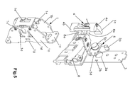
- Figure 5 illustrates the application of the proposed device for a touchbar-type panic lock, from where it may be deduced that the opening manoeuvre is identical to that explained for the pushbar, with the sole particularity that the tongues (8a) are now in charge of the function entrusted before to the second lug (7c).
- the body of the case (1) is symmetrical in relation to the transverse and horizontal mid plane thereof; that the base plate (3) is symmetrical in relation to its transverse and horizontal mid plane; and that the first-order lever (4) is symmetrical in relation to its transverse and horizontal mid plane.
Landscapes
- Business, Economics & Management (AREA)
- Emergency Management (AREA)
- Lock And Its Accessories (AREA)
- Extensible Doors And Revolving Doors (AREA)
- Hinges (AREA)
- Bay Windows, Entrances, And Structural Adjustments Related Thereto (AREA)
- Operating, Guiding And Securing Of Roll- Type Closing Members (AREA)
Abstract
Description
- This invention relates to a device of modular design having a reversible nature and that can be actuated in a multipurpose manner by the panic locks that are installed in emergency exit doors and have a main lock mechanism, provided or not with a locking bolt, and/or upper (on the lintel) and lower (on the threshold) locking points, and/or side locking points on the door frame post, and where said main lock is actuated by means of a bar that is transversally installed on the door.
- In particular, the object of this invention is intended for application in locks mortised in the thickness of doors.
- Two types of panic bars are known and frequently used in this field. One of them consists in a pushbar that is articulated at its ends to carry out, by means of two connecting rods, a collapsing rotation on the door; this type is known in this field by its English name, pushbar, which will be the one used hereinafter. The other type consists in a bar that includes an outer casing capable of linear movement perpendicular to the door; this type is known in this field by its English name, touchbar, which will be the one used hereinafter.
- The current situation is that there are two different concepts of panic bar (pushbar and touchbar) and, within each one of them, there exist all the alternatives indicated above: a main lock having a bolt or lacking one; that the main lock also has to actuate side returns located at a different height than the door; that upper and lower returns also have to be actuated from the main lock.
- Thus, each one of these options corresponds nowadays to its own and exclusive design such that manufacturers and the distribution chain of this type of product face big design, material-procurement, production, storage and distribution problems.
- In contrast to this state of affairs, this invention proposes a device of a modular and compact design that is going to allow it to be applied to the different alternatives of execution existing nowadays - described above - and particularly for mortise locks.
- To this end, the proposed device comprises a case that is fastened to a door by means of a base plate, a first-order lever that has a vertical axis of rotation in the case, and a cam with a reciprocal topography of facing surfaces that belong to the base plate and to a floor wall of the case, this cam having its virtual axis of rotation in a hollow that is reciprocal to the square shaft of a lock mortised in the thickness of the door, this hollow being in a shaft journal that is reciprocal to a bearing of the base plate, the case of which has a first vertical sidewall provided with a complementary window of the shaft hub of the connecting rod of a pushbar of a panic locking mechanism installed across the width of the inner side of the door, there being in this first sidewall at least one reciprocally wide slot of the thickness of a tongue belonging to the end swinging arm of a panic locking device actuated by means of a pushbar, the first-order lever of which has a first arm in contact with a projecting part of the shaft hub on a face thereof that is frontal with regard to its rotation during the collapse of the connecting rod, the first-order lever of which has a second arm with its front in contact with a protruding part of the cam on a face thereof that is rear with regard to the rotation of the square shaft consistent with the opening of the mechanism of the mortise lock. In this mechanical design, the following conditions are met with regard to the position of assembly of the device on the door: that the body of the case is symmetrical in relation to the transverse and horizontal mid plane thereof; that the base plate is symmetrical in relation to its transverse and horizontal mid plane; and that the first-order lever is symmetrical in relation to its transverse and horizontal mid plane.
- According to this setup, when the use of a pushbar-type panic lock is desired, the hub of the shaft of the connecting rod of the corresponding pushbar is coupled in the window of the first sidewall of the case, whereupon the second lug stays (according to the direction of rotation of the opening of the lock) behind the first arm of the first-order lever; on the other hand, since the second arm also stays behind the first lug associated with the cam, and since this cam is coupled to the square shaft of the mortise lock, it turns out that, upon the actuation of the pushbar, the second lug makes the first-order lever rotate and, in turn, the latter makes the cam rotate, dragging with it the square shaft of the mortise lock.
- On the other hand, when the use of a touchbar-type panic lock is preferred, the slots of the first sidewall of the case come into play such that the tongues of the end swinging arm characteristic of the touchbar go into them to end positioned (as in the case of the second lug of the pushbar) behind the first arm of the first-order lever; then, when the touchbar is actuated, the tongues make the first-order lever rotate and, as before, the second arm thereof will make the cam that transmits the rotation of the square shaft rotate, causing the mortise lock to open.
- That said, the properties of the device have been explained as for a compact, modular and multipurpose design as regards its application for pushbar and touchbar panic locks alike. To use the reversibility property such that the same device may be used for doors opening to the left or to the right, it will suffice to invert the position of the case from top to bottom without it being necessary to do the same with the first-order lever; as for the cam and the base plate, the inversion or not of their position following the inversion of the case might not be necessary, in each case depending on the direction of rotation required for the square shaft of the mortise lock.
- In order to better understand the nature of the invention, an industrial embodiment is depicted in the attached drawings as a merely illustrative and non-limiting example.
-
Figure 1 is an exploded perspective view of the device of the invention, wherein a mortise lock (6) housed in a door (2) is included, as well as a second perspective of the case (1) seen from its second sidewall (1b). The depictions of a connecting rod (7a) of a pushbar-type panic lock and a swinging arm (8) of a touchbar-type panic lock have also been included in thisFigure 1 . -
Figure 2 is an exploded perspective view similar to that ofFigure 1 illustrating the application of the device for a panic lock of the type actuated by a pushbar (7); the depictions of the mortise lock (6) and the door (2) have been omitted in it. -
Figure 3 depicts in orthogonal projection the plan view of the exploded assembly ofFigure 2 , in the rest or neutral position of the device of the invention. -
Figure 4 is likeFigure 3 but relating to an actuated position for the opening of the mortise lock (6). -
Figure 5 is an exploded perspective view similar to that ofFigure 2 but relating to the application of the device for a panic lock of the type actuated by non-collapsible pushing by means of swinging arms (8). - The following reference numbers appear in these figures:
- 1. Case
- 1a. First sidewall of the case (1)
- 1b. Second sidewall of the case (1)
- 1c. Window in the first sidewall (1a) 1d. Slots in the first sidewall (1a)
- 1e. Folds of the second sidewall (1b)
- 1f. Floor wall of the case (1)
- 1g. Seat of the floor wall (1f)
- 2. Door
- 3. Base plate
- 3a. Bearing of the base plate (3)
- 3b. Mortise of the base plate (3)
- 4. First-order lever
- 4a. Axis of rotation of the first-order lever (4)
- 4b. First arm of the first-order lever (4)
- 4c. Second arm of the first-order lever (4)
- 5. Cam
- 5a. Square hollow in the cam
- 5b. Protruding part or first lug of the cam (5)
- 5c. Shaft journal in the cam (5)
- 5d. Pin of the cam (5)
- 6. Mortise lock
- 6a. Square shaft of the mortise lock
- 7. Pushbar
- 7a. Connecting rod of the pushbar (7)
- 7b. Shaft hub of the connecting rod (7a)
- 7c. Projecting part or second lug of the hub (7b)
- 8. Swinging arm
- 8a. Tongues of the swinging arm (8)
- In relation to the drawings and reference numbers listed above, a preferred embodiment of the object of the invention is depicted in the attached plans that is related to a device of modular design, specially intended for application in locks that are mortised in the thickness of doors, that is reversible and can be actuated in a multipurpose manner by the panic locks that are installed in emergency exit doors and have a main lock mechanism, provided or not with a locking bolt, and/or upper (on the lintel) and lower (on the threshold) locking points, and/or side locking points on the door frame post, and where said main lock is actuated by means of a bar that is transversally installed on the door.
- As
Figure 1 shows, said device comprises a case (1) that is fastened to a door (2) by means of a base plate (3), a first-order lever (4) that has a vertical axis of rotation (4a) in the case (1), and a cam (5) with a reciprocal topography of facing surfaces that belong to the base plate (3) and to a floor wall (1f) of the case (1), this cam (5) having its virtual axis of rotation in a hollow (5a) that is reciprocal to the square shaft (6a) of a lock (6) mortised in the thickness of the door (2), this hollow being in a shaft journal (5c) that is reciprocal to a bearing (3a) of the base plate (3), the case (1) of which has a first vertical sidewall (1a) provided with a complementary window (1c) of the shaft hub (7b) of the connecting rod (7a) of a pushbar (7) of a panic locking mechanism installed across the width of the inner side of the door (2), there being in this first sidewall (1a) at least one reciprocally wide slot (1d) of the thickness of a tongue (8a) belonging to the end swinging arm (8) of a panic locking device actuated by means of a pushbar, the first-order lever (4) of which has a first arm (4b) in contact with a projecting part (7c) of the shaft hub (7b) on a face thereof that is frontal with regard to its rotation during the collapse of the connecting rod (7a), the first-order lever (4) of which has a second arm (4c) with its front in contact with a protruding part (5b) of the cam (5) on a face thereof that is rear with regard to the rotation of the square shaft (6a) consistent with the opening of the mechanism of the mortise lock (6). According to a preferred embodiment, it is true that the vertical axis of rotation (4a) of the first-order lever (4) has its ends resting on seats included in the case (1) which, as can be seen inFigures 1 ,2 and5 , are folds (1e) of the second vertical sidewall (1b) of the case (1); likewise, the following is true: that in the first sidewall (1a) two are the slots (1d) that are provided for as many other tongues (8a) of the end swinging arm (8) of a pushbar-type panic locking mechanism; that the protruding part (5b) of the cam (5) is a first lug; and that the projecting part (7c) of the shaft hub (7b) of the connecting rod (7a) is a second lug. -
Figures 2 to 4 illustrate the application of the invention for a pushbar-type panic bar and are useful to explain its simple operation.Figures 2 and 3 relate to the neutral or rest state of the device, where the second lug (7c) stays behind the first arm (4b) of the first-order lever (4) (according to the stated convention for the direction of rotation of the opening manoeuvre), whilst the first lug (5b) of the cam stays front of the second arm (4c) of said first-order lever (4); when the bar (7) is lowered, the second lug (4b) causes a rotation of the first-order lever (4) which, through its second arm (4c) and the first lug (5b), is transmitted to the cam (5) which, due to being coupled to the square shaft (6a), causes in the latter the rotation needed to open the lock (6), this being the final position that is depicted inFigure 4 . -
Figure 5 illustrates the application of the proposed device for a touchbar-type panic lock, from where it may be deduced that the opening manoeuvre is identical to that explained for the pushbar, with the sole particularity that the tongues (8a) are now in charge of the function entrusted before to the second lug (7c). - According to other particularities of the invention, the following is true in the proposed device and with regard to the assembly position of the case (1) on the door (2): that the body of the case (1) is symmetrical in relation to the transverse and horizontal mid plane thereof; that the base plate (3) is symmetrical in relation to its transverse and horizontal mid plane; and that the first-order lever (4) is symmetrical in relation to its transverse and horizontal mid plane. With these conditions, a reversible application of the device is obtained, it being possible to use it for doors opening to either the right or the left, it sufficing to this end to turn the case (1) upside down and, according to the direction of rotation that is required for the square shaft (6a), also the cam (5) and the base plate (3) or not; evidently, the rotation of one of the these two parts involves that of the other.
- As for the assembly of the cam (5), another particularity of the invention consists in the topography of the cam (5) being reciprocal to a seat (1g) that has been made in the floor wall (1f) of the case (1) as well as it forming (
Figure 5 ) a projecting pin (5d) that is reciprocal to a mortise (3b) made in the base plate (3).
Claims (11)
- A reversible and multipurpose modular panic locking device for mortise locks, characterised in that it comprises a case (1) that is fastened to a door (2) by means of a base plate (3), a first-order lever (4) that has a vertical axis of rotation (4a) in the case (1), and a cam (5) with a reciprocal topography of facing surfaces that belong to the base plate (3) and to a floor wall (1f) of the case (1), this cam (5) having its virtual axis of rotation in a hollow (5a) that is reciprocal to the square shaft (6a) of a lock (6) mortised in the thickness of the door (2), this hollow being in a shaft journal (5c) that is reciprocal to a bearing (3a) of the base plate (3), the case (1) of which has a first vertical sidewall (1a) provided with a complementary window (1c) of the shaft hub (7b) of the connecting rod (7a) of a pushbar (7) of a panic locking mechanism installed across the width of the inner side of the door (2), there being in this first sidewall (1a) at least one reciprocally wide slot (1d) of the thickness of a tongue (8a) belonging to the end swinging arm (8) of a panic locking device actuated by means of a pushbar, the first-order lever (4) of which has a first arm (4b) in contact with a projecting part (7c) of the shaft hub (7b) on a face thereof that is frontal with regard to its rotation during the collapse of the connecting rod (7a), the first-order lever (4) of which has a second arm (4c) with its front in contact with a protruding part (5b) of the cam (5) on a face thereof that is rear with regard to the rotation of the square shaft (6a) consistent with the opening of the mechanism of the mortise lock (6).
- The reversible and multipurpose modular panic locking device for mortise locks according to the first claim, characterised in that the vertical axis of rotation (4a) of the first-order lever (4) has its ends resting on seats included in the case (1).
- The reversible and multipurpose modular panic locking device for mortise locks according to the preceding claims, characterised in that the seats of the axis of rotation (4a) of the first-order lever (4) are folds (1 e) of the second sidewall (1b) of the case (1).
- The reversible and multipurpose modular panic locking device for mortise locks according to one or more of the preceding claims, characterised in that in the first sidewall (1a) there are two reciprocally wide slots (1d) of the thickness of two tongues (8a) of the end swinging arm (8) of a panic locking mechanism actuated by means of a pushbar.
- The reversible and multipurpose modular panic locking device for mortise locks according to one or more of the preceding claims, characterised in that the protruding part (5b) of the cam (5) is a first lug.
- The reversible and multipurpose modular panic locking device for mortise locks according to one or more of the preceding claims, characterised in that the projecting part (7c) of the shaft hub (7b) of the connecting rod (7a) is a second lug.
- The reversible and multipurpose modular panic locking device for mortise locks according to the preceding claims, characterised in that, with regard to its assembly position on the door (2), the body of the case (1) is symmetrical in relation to the transverse and horizontal mid plane thereof.
- The reversible and multipurpose modular panic locking device for mortise locks according to the preceding claims, characterised in that, with regard to the assembly position of the case (1) on the door (2), the base plate (3) is symmetrical in relation to its transverse and horizontal mid plane.
- The reversible and multipurpose modular panic locking device for mortise locks according to the preceding claims, characterised in that, with regard to the assembly position of the case (1) on the door (2), the first-order lever (4) is symmetrical in relation to its transverse and horizontal mid plane.
- The reversible and multipurpose modular panic locking device for mortise locks according to one or more of the preceding claims, characterised in that the topography of the cam (5) is reciprocal to a seat (1g) that has been made in the floor wall (1f) of the case (1).
- The reversible and multipurpose modular panic locking device for mortise locks according to one or more of the preceding claims, characterised in that the topography of the cam (5) forms a projecting pin (5d) that is reciprocal to a mortise (3b) made in the base plate (3).
Priority Applications (1)
| Application Number | Priority Date | Filing Date | Title |
|---|---|---|---|
| PL10164977T PL2273043T3 (en) | 2009-06-05 | 2010-06-04 | Modular device, reversible and polyvalent, of antipanic closure for mortise locks |
Applications Claiming Priority (1)
| Application Number | Priority Date | Filing Date | Title |
|---|---|---|---|
| ES200901373A ES2378201B1 (en) | 2009-06-05 | 2009-06-05 | MODULAR REVERSIBLE AND POLIVALENT ANTIPANIC CLOSURE DEVICE FOR EMBUTIR LOCKS. |
Publications (3)
| Publication Number | Publication Date |
|---|---|
| EP2273043A2 true EP2273043A2 (en) | 2011-01-12 |
| EP2273043A3 EP2273043A3 (en) | 2013-09-04 |
| EP2273043B1 EP2273043B1 (en) | 2015-11-25 |
Family
ID=43065718
Family Applications (1)
| Application Number | Title | Priority Date | Filing Date |
|---|---|---|---|
| EP10164977.0A Active EP2273043B1 (en) | 2009-06-05 | 2010-06-04 | Modular device, reversible and polyvalent, of antipanic closure for mortise locks |
Country Status (6)
| Country | Link |
|---|---|
| EP (1) | EP2273043B1 (en) |
| CL (1) | CL2010000545A1 (en) |
| CO (1) | CO6340182A1 (en) |
| ES (1) | ES2378201B1 (en) |
| PE (1) | PE20110006A1 (en) |
| PL (1) | PL2273043T3 (en) |
Cited By (1)
| Publication number | Priority date | Publication date | Assignee | Title |
|---|---|---|---|---|
| WO2014041135A1 (en) * | 2012-09-13 | 2014-03-20 | Assa Abloy Sicherheitstechnik Gmbh | Fitting with an actuating handle for a door, window or similar comprising and adapter bearing plate |
Family Cites Families (6)
| Publication number | Priority date | Publication date | Assignee | Title |
|---|---|---|---|---|
| IT1298626B1 (en) * | 1998-03-11 | 2000-01-12 | Gebhard Heinrad Locher | HANDLE WITH PUSHING OPERATION FOR DOORS IN GENERAL |
| ES2217910B1 (en) * | 2001-12-07 | 2005-06-01 | Talleres De Escoriaza, S.A. | DEVICE FOR AN ANTIPANIC LOCK. |
| ITMI20020475A1 (en) * | 2002-03-07 | 2003-09-08 | Iseo Serrature Spa | CONTROL DEVICE FOR PANIC HANDLES |
| ITTO20020281A1 (en) * | 2002-03-29 | 2003-09-29 | Savio Spa | ,, PANIC OPENING SYSTEM FOR DOORS ,,. |
| FR2861789B1 (en) * | 2003-11-05 | 2006-01-27 | Vachette Sa | ANTI-PANIC MULTIPOINT REVERSIBLE LOCK |
| ES2301387B1 (en) * | 2006-10-10 | 2009-03-01 | Talleres De Escoriaza, S.A. | "REVERSIBLE AND POLIVALENT ANTIPANIC CLOSURE MODULATING DEVICE". |
-
2009
- 2009-06-05 ES ES200901373A patent/ES2378201B1/en active Active
-
2010
- 2010-05-26 CL CL2010000545A patent/CL2010000545A1/en unknown
- 2010-05-28 PE PE2010000318A patent/PE20110006A1/en not_active Application Discontinuation
- 2010-05-28 CO CO10064177A patent/CO6340182A1/en active IP Right Grant
- 2010-06-04 EP EP10164977.0A patent/EP2273043B1/en active Active
- 2010-06-04 PL PL10164977T patent/PL2273043T3/en unknown
Non-Patent Citations (1)
| Title |
|---|
| None |
Cited By (1)
| Publication number | Priority date | Publication date | Assignee | Title |
|---|---|---|---|---|
| WO2014041135A1 (en) * | 2012-09-13 | 2014-03-20 | Assa Abloy Sicherheitstechnik Gmbh | Fitting with an actuating handle for a door, window or similar comprising and adapter bearing plate |
Also Published As
| Publication number | Publication date |
|---|---|
| CO6340182A1 (en) | 2011-11-21 |
| CL2010000545A1 (en) | 2011-01-28 |
| EP2273043B1 (en) | 2015-11-25 |
| PE20110006A1 (en) | 2011-01-21 |
| ES2378201A1 (en) | 2012-04-10 |
| ES2378201B1 (en) | 2012-08-06 |
| PL2273043T3 (en) | 2016-05-31 |
| EP2273043A3 (en) | 2013-09-04 |
Similar Documents
| Publication | Publication Date | Title |
|---|---|---|
| US3454299A (en) | Double-hinged tailgate | |
| US3857594A (en) | Door lock assembly | |
| CN102264992A (en) | high security lock for door | |
| US20140326721A1 (en) | Locking system applicable in large container | |
| US2219132A (en) | Electric door lock | |
| EP2273043B1 (en) | Modular device, reversible and polyvalent, of antipanic closure for mortise locks | |
| JPS5848715B2 (en) | Door lock with key-operated locking cylinder | |
| MX2007015514A (en) | Modular closure latch mechanism. | |
| KR101256040B1 (en) | A handle for sliding door | |
| CN109914950B (en) | Window lock and window based on window lock | |
| EP2985399B1 (en) | Handle for a door or window with two or three point latch | |
| KR101674167B1 (en) | A non-power type bidirectional operation mortise | |
| EP2171187B1 (en) | Lock for reinforced doors and the like comprising a selector | |
| EP2148029A1 (en) | Automatic lock | |
| EP1806706B1 (en) | Anti-theft case for amusement and game of chance machines | |
| US3582120A (en) | Cargo door latching mechanism | |
| EP3599328B1 (en) | Panic lock for doors | |
| KR101949341B1 (en) | A toolbox locking apparatus | |
| JP2009016060A (en) | Safety switch | |
| CN101815835A (en) | Antipanic lock | |
| JP2528753B2 (en) | Window shoji control device | |
| US3469876A (en) | Unit lock dual dead bolts | |
| KR101405423B1 (en) | Lever type door lock | |
| JPH0377915B2 (en) | ||
| JP2668674B2 (en) | Child door lock |
Legal Events
| Date | Code | Title | Description |
|---|---|---|---|
| PUAI | Public reference made under article 153(3) epc to a published international application that has entered the european phase |
Free format text: ORIGINAL CODE: 0009012 |
|
| AK | Designated contracting states |
Kind code of ref document: A2 Designated state(s): AL AT BE BG CH CY CZ DE DK EE ES FI FR GB GR HR HU IE IS IT LI LT LU LV MC MK MT NL NO PL PT RO SE SI SK SM TR |
|
| AX | Request for extension of the european patent |
Extension state: BA ME RS |
|
| PUAL | Search report despatched |
Free format text: ORIGINAL CODE: 0009013 |
|
| AK | Designated contracting states |
Kind code of ref document: A3 Designated state(s): AL AT BE BG CH CY CZ DE DK EE ES FI FR GB GR HR HU IE IS IT LI LT LU LV MC MK MT NL NO PL PT RO SE SI SK SM TR |
|
| AX | Request for extension of the european patent |
Extension state: BA ME RS |
|
| RIC1 | Information provided on ipc code assigned before grant |
Ipc: E05B 65/10 20060101AFI20130730BHEP Ipc: E05B 3/00 20060101ALI20130730BHEP |
|
| 17P | Request for examination filed |
Effective date: 20140303 |
|
| RBV | Designated contracting states (corrected) |
Designated state(s): AL AT BE BG CH CY CZ DE DK EE ES FI FR GB GR HR HU IE IS IT LI LT LU LV MC MK MT NL NO PL PT RO SE SI SK SM TR |
|
| GRAP | Despatch of communication of intention to grant a patent |
Free format text: ORIGINAL CODE: EPIDOSNIGR1 |
|
| INTG | Intention to grant announced |
Effective date: 20150610 |
|
| GRAS | Grant fee paid |
Free format text: ORIGINAL CODE: EPIDOSNIGR3 |
|
| GRAA | (expected) grant |
Free format text: ORIGINAL CODE: 0009210 |
|
| AK | Designated contracting states |
Kind code of ref document: B1 Designated state(s): AL AT BE BG CH CY CZ DE DK EE ES FI FR GB GR HR HU IE IS IT LI LT LU LV MC MK MT NL NO PL PT RO SE SI SK SM TR |
|
| REG | Reference to a national code |
Ref country code: GB Ref legal event code: FG4D |
|
| REG | Reference to a national code |
Ref country code: CH Ref legal event code: EP |
|
| REG | Reference to a national code |
Ref country code: AT Ref legal event code: REF Ref document number: 762712 Country of ref document: AT Kind code of ref document: T Effective date: 20151215 |
|
| REG | Reference to a national code |
Ref country code: IE Ref legal event code: FG4D |
|
| REG | Reference to a national code |
Ref country code: DE Ref legal event code: R096 Ref document number: 602010029130 Country of ref document: DE |
|
| REG | Reference to a national code |
Ref country code: LT Ref legal event code: MG4D |
|
| REG | Reference to a national code |
Ref country code: NL Ref legal event code: MP Effective date: 20160225 |
|
| REG | Reference to a national code |
Ref country code: PT Ref legal event code: SC4A Free format text: AVAILABILITY OF NATIONAL TRANSLATION Effective date: 20151211 |
|
| REG | Reference to a national code |
Ref country code: AT Ref legal event code: MK05 Ref document number: 762712 Country of ref document: AT Kind code of ref document: T Effective date: 20151125 |
|
| PG25 | Lapsed in a contracting state [announced via postgrant information from national office to epo] |
Ref country code: IS Free format text: LAPSE BECAUSE OF FAILURE TO SUBMIT A TRANSLATION OF THE DESCRIPTION OR TO PAY THE FEE WITHIN THE PRESCRIBED TIME-LIMIT Effective date: 20160325 Ref country code: NL Free format text: LAPSE BECAUSE OF FAILURE TO SUBMIT A TRANSLATION OF THE DESCRIPTION OR TO PAY THE FEE WITHIN THE PRESCRIBED TIME-LIMIT Effective date: 20151125 Ref country code: HR Free format text: LAPSE BECAUSE OF FAILURE TO SUBMIT A TRANSLATION OF THE DESCRIPTION OR TO PAY THE FEE WITHIN THE PRESCRIBED TIME-LIMIT Effective date: 20151125 Ref country code: NO Free format text: LAPSE BECAUSE OF FAILURE TO SUBMIT A TRANSLATION OF THE DESCRIPTION OR TO PAY THE FEE WITHIN THE PRESCRIBED TIME-LIMIT Effective date: 20160225 Ref country code: ES Free format text: LAPSE BECAUSE OF FAILURE TO SUBMIT A TRANSLATION OF THE DESCRIPTION OR TO PAY THE FEE WITHIN THE PRESCRIBED TIME-LIMIT Effective date: 20151125 Ref country code: LT Free format text: LAPSE BECAUSE OF FAILURE TO SUBMIT A TRANSLATION OF THE DESCRIPTION OR TO PAY THE FEE WITHIN THE PRESCRIBED TIME-LIMIT Effective date: 20151125 |
|
| REG | Reference to a national code |
Ref country code: FR Ref legal event code: PLFP Year of fee payment: 7 |
|
| PG25 | Lapsed in a contracting state [announced via postgrant information from national office to epo] |
Ref country code: LV Free format text: LAPSE BECAUSE OF FAILURE TO SUBMIT A TRANSLATION OF THE DESCRIPTION OR TO PAY THE FEE WITHIN THE PRESCRIBED TIME-LIMIT Effective date: 20151125 Ref country code: AT Free format text: LAPSE BECAUSE OF FAILURE TO SUBMIT A TRANSLATION OF THE DESCRIPTION OR TO PAY THE FEE WITHIN THE PRESCRIBED TIME-LIMIT Effective date: 20151125 Ref country code: SE Free format text: LAPSE BECAUSE OF FAILURE TO SUBMIT A TRANSLATION OF THE DESCRIPTION OR TO PAY THE FEE WITHIN THE PRESCRIBED TIME-LIMIT Effective date: 20151125 Ref country code: FI Free format text: LAPSE BECAUSE OF FAILURE TO SUBMIT A TRANSLATION OF THE DESCRIPTION OR TO PAY THE FEE WITHIN THE PRESCRIBED TIME-LIMIT Effective date: 20151125 |
|
| REG | Reference to a national code |
Ref country code: DE Ref legal event code: R097 Ref document number: 602010029130 Country of ref document: DE |
|
| PG25 | Lapsed in a contracting state [announced via postgrant information from national office to epo] |
Ref country code: EE Free format text: LAPSE BECAUSE OF FAILURE TO SUBMIT A TRANSLATION OF THE DESCRIPTION OR TO PAY THE FEE WITHIN THE PRESCRIBED TIME-LIMIT Effective date: 20151125 Ref country code: DK Free format text: LAPSE BECAUSE OF FAILURE TO SUBMIT A TRANSLATION OF THE DESCRIPTION OR TO PAY THE FEE WITHIN THE PRESCRIBED TIME-LIMIT Effective date: 20151125 Ref country code: SM Free format text: LAPSE BECAUSE OF FAILURE TO SUBMIT A TRANSLATION OF THE DESCRIPTION OR TO PAY THE FEE WITHIN THE PRESCRIBED TIME-LIMIT Effective date: 20151125 Ref country code: SK Free format text: LAPSE BECAUSE OF FAILURE TO SUBMIT A TRANSLATION OF THE DESCRIPTION OR TO PAY THE FEE WITHIN THE PRESCRIBED TIME-LIMIT Effective date: 20151125 Ref country code: RO Free format text: LAPSE BECAUSE OF FAILURE TO SUBMIT A TRANSLATION OF THE DESCRIPTION OR TO PAY THE FEE WITHIN THE PRESCRIBED TIME-LIMIT Effective date: 20151125 |
|
| PLBE | No opposition filed within time limit |
Free format text: ORIGINAL CODE: 0009261 |
|
| STAA | Information on the status of an ep patent application or granted ep patent |
Free format text: STATUS: NO OPPOSITION FILED WITHIN TIME LIMIT |
|
| 26N | No opposition filed |
Effective date: 20160826 |
|
| PG25 | Lapsed in a contracting state [announced via postgrant information from national office to epo] |
Ref country code: SI Free format text: LAPSE BECAUSE OF FAILURE TO SUBMIT A TRANSLATION OF THE DESCRIPTION OR TO PAY THE FEE WITHIN THE PRESCRIBED TIME-LIMIT Effective date: 20151125 |
|
| PG25 | Lapsed in a contracting state [announced via postgrant information from national office to epo] |
Ref country code: BE Free format text: LAPSE BECAUSE OF FAILURE TO SUBMIT A TRANSLATION OF THE DESCRIPTION OR TO PAY THE FEE WITHIN THE PRESCRIBED TIME-LIMIT Effective date: 20151125 |
|
| REG | Reference to a national code |
Ref country code: DE Ref legal event code: R119 Ref document number: 602010029130 Country of ref document: DE |
|
| PG25 | Lapsed in a contracting state [announced via postgrant information from national office to epo] |
Ref country code: MC Free format text: LAPSE BECAUSE OF FAILURE TO SUBMIT A TRANSLATION OF THE DESCRIPTION OR TO PAY THE FEE WITHIN THE PRESCRIBED TIME-LIMIT Effective date: 20151125 |
|
| REG | Reference to a national code |
Ref country code: CH Ref legal event code: PL |
|
| GBPC | Gb: european patent ceased through non-payment of renewal fee |
Effective date: 20160604 |
|
| REG | Reference to a national code |
Ref country code: IE Ref legal event code: MM4A |
|
| PG25 | Lapsed in a contracting state [announced via postgrant information from national office to epo] |
Ref country code: CH Free format text: LAPSE BECAUSE OF NON-PAYMENT OF DUE FEES Effective date: 20160630 Ref country code: DE Free format text: LAPSE BECAUSE OF NON-PAYMENT OF DUE FEES Effective date: 20170103 Ref country code: LI Free format text: LAPSE BECAUSE OF NON-PAYMENT OF DUE FEES Effective date: 20160630 |
|
| REG | Reference to a national code |
Ref country code: FR Ref legal event code: PLFP Year of fee payment: 8 |
|
| PG25 | Lapsed in a contracting state [announced via postgrant information from national office to epo] |
Ref country code: GB Free format text: LAPSE BECAUSE OF NON-PAYMENT OF DUE FEES Effective date: 20160604 Ref country code: IE Free format text: LAPSE BECAUSE OF NON-PAYMENT OF DUE FEES Effective date: 20160604 |
|
| REG | Reference to a national code |
Ref country code: FR Ref legal event code: PLFP Year of fee payment: 9 |
|
| PG25 | Lapsed in a contracting state [announced via postgrant information from national office to epo] |
Ref country code: HU Free format text: LAPSE BECAUSE OF FAILURE TO SUBMIT A TRANSLATION OF THE DESCRIPTION OR TO PAY THE FEE WITHIN THE PRESCRIBED TIME-LIMIT; INVALID AB INITIO Effective date: 20100604 Ref country code: CY Free format text: LAPSE BECAUSE OF FAILURE TO SUBMIT A TRANSLATION OF THE DESCRIPTION OR TO PAY THE FEE WITHIN THE PRESCRIBED TIME-LIMIT Effective date: 20151125 |
|
| PG25 | Lapsed in a contracting state [announced via postgrant information from national office to epo] |
Ref country code: LU Free format text: LAPSE BECAUSE OF NON-PAYMENT OF DUE FEES Effective date: 20160604 Ref country code: GR Free format text: LAPSE BECAUSE OF FAILURE TO SUBMIT A TRANSLATION OF THE DESCRIPTION OR TO PAY THE FEE WITHIN THE PRESCRIBED TIME-LIMIT Effective date: 20151125 Ref country code: MT Free format text: LAPSE BECAUSE OF NON-PAYMENT OF DUE FEES Effective date: 20160630 Ref country code: TR Free format text: LAPSE BECAUSE OF FAILURE TO SUBMIT A TRANSLATION OF THE DESCRIPTION OR TO PAY THE FEE WITHIN THE PRESCRIBED TIME-LIMIT Effective date: 20151125 Ref country code: MK Free format text: LAPSE BECAUSE OF FAILURE TO SUBMIT A TRANSLATION OF THE DESCRIPTION OR TO PAY THE FEE WITHIN THE PRESCRIBED TIME-LIMIT Effective date: 20151125 |
|
| PG25 | Lapsed in a contracting state [announced via postgrant information from national office to epo] |
Ref country code: BG Free format text: LAPSE BECAUSE OF FAILURE TO SUBMIT A TRANSLATION OF THE DESCRIPTION OR TO PAY THE FEE WITHIN THE PRESCRIBED TIME-LIMIT Effective date: 20151125 |
|
| PG25 | Lapsed in a contracting state [announced via postgrant information from national office to epo] |
Ref country code: AL Free format text: LAPSE BECAUSE OF FAILURE TO SUBMIT A TRANSLATION OF THE DESCRIPTION OR TO PAY THE FEE WITHIN THE PRESCRIBED TIME-LIMIT Effective date: 20151125 |
|
| PGFP | Annual fee paid to national office [announced via postgrant information from national office to epo] |
Ref country code: PL Payment date: 20250515 Year of fee payment: 16 |
|
| PGFP | Annual fee paid to national office [announced via postgrant information from national office to epo] |
Ref country code: IT Payment date: 20250522 Year of fee payment: 16 |
|
| PGFP | Annual fee paid to national office [announced via postgrant information from national office to epo] |
Ref country code: PT Payment date: 20250602 Year of fee payment: 16 |
|
| PGFP | Annual fee paid to national office [announced via postgrant information from national office to epo] |
Ref country code: FR Payment date: 20250523 Year of fee payment: 16 |
|
| PGFP | Annual fee paid to national office [announced via postgrant information from national office to epo] |
Ref country code: CZ Payment date: 20250529 Year of fee payment: 16 |