EP2271113A1 - Time-varying image encoding and decoding device - Google Patents
Time-varying image encoding and decoding device Download PDFInfo
- Publication number
- EP2271113A1 EP2271113A1 EP09738875A EP09738875A EP2271113A1 EP 2271113 A1 EP2271113 A1 EP 2271113A1 EP 09738875 A EP09738875 A EP 09738875A EP 09738875 A EP09738875 A EP 09738875A EP 2271113 A1 EP2271113 A1 EP 2271113A1
- Authority
- EP
- European Patent Office
- Prior art keywords
- image signal
- signal
- image
- filter
- rounding offset
- Prior art date
- Legal status (The legal status is an assumption and is not a legal conclusion. Google has not performed a legal analysis and makes no representation as to the accuracy of the status listed.)
- Withdrawn
Links
- 238000000034 method Methods 0.000 claims abstract description 40
- 238000001914 filtration Methods 0.000 claims abstract description 32
- 230000007423 decrease Effects 0.000 claims description 5
- 230000015654 memory Effects 0.000 description 22
- 230000003247 decreasing effect Effects 0.000 description 6
- 238000010586 diagram Methods 0.000 description 6
- 230000001131 transforming effect Effects 0.000 description 2
- 238000009825 accumulation Methods 0.000 description 1
- 230000005540 biological transmission Effects 0.000 description 1
- 238000004891 communication Methods 0.000 description 1
- 230000006835 compression Effects 0.000 description 1
- 238000007906 compression Methods 0.000 description 1
- 230000000694 effects Effects 0.000 description 1
- 230000003287 optical effect Effects 0.000 description 1
- 239000004065 semiconductor Substances 0.000 description 1
Images



Classifications
-
- H—ELECTRICITY
- H04—ELECTRIC COMMUNICATION TECHNIQUE
- H04N—PICTORIAL COMMUNICATION, e.g. TELEVISION
- H04N19/00—Methods or arrangements for coding, decoding, compressing or decompressing digital video signals
- H04N19/85—Methods or arrangements for coding, decoding, compressing or decompressing digital video signals using pre-processing or post-processing specially adapted for video compression
-
- H—ELECTRICITY
- H04—ELECTRIC COMMUNICATION TECHNIQUE
- H04N—PICTORIAL COMMUNICATION, e.g. TELEVISION
- H04N19/00—Methods or arrangements for coding, decoding, compressing or decompressing digital video signals
- H04N19/10—Methods or arrangements for coding, decoding, compressing or decompressing digital video signals using adaptive coding
- H04N19/102—Methods or arrangements for coding, decoding, compressing or decompressing digital video signals using adaptive coding characterised by the element, parameter or selection affected or controlled by the adaptive coding
- H04N19/117—Filters, e.g. for pre-processing or post-processing
-
- H—ELECTRICITY
- H04—ELECTRIC COMMUNICATION TECHNIQUE
- H04N—PICTORIAL COMMUNICATION, e.g. TELEVISION
- H04N19/00—Methods or arrangements for coding, decoding, compressing or decompressing digital video signals
- H04N19/10—Methods or arrangements for coding, decoding, compressing or decompressing digital video signals using adaptive coding
- H04N19/134—Methods or arrangements for coding, decoding, compressing or decompressing digital video signals using adaptive coding characterised by the element, parameter or criterion affecting or controlling the adaptive coding
- H04N19/136—Incoming video signal characteristics or properties
- H04N19/137—Motion inside a coding unit, e.g. average field, frame or block difference
-
- H—ELECTRICITY
- H04—ELECTRIC COMMUNICATION TECHNIQUE
- H04N—PICTORIAL COMMUNICATION, e.g. TELEVISION
- H04N19/00—Methods or arrangements for coding, decoding, compressing or decompressing digital video signals
- H04N19/10—Methods or arrangements for coding, decoding, compressing or decompressing digital video signals using adaptive coding
- H04N19/169—Methods or arrangements for coding, decoding, compressing or decompressing digital video signals using adaptive coding characterised by the coding unit, i.e. the structural portion or semantic portion of the video signal being the object or the subject of the adaptive coding
- H04N19/17—Methods or arrangements for coding, decoding, compressing or decompressing digital video signals using adaptive coding characterised by the coding unit, i.e. the structural portion or semantic portion of the video signal being the object or the subject of the adaptive coding the unit being an image region, e.g. an object
- H04N19/172—Methods or arrangements for coding, decoding, compressing or decompressing digital video signals using adaptive coding characterised by the coding unit, i.e. the structural portion or semantic portion of the video signal being the object or the subject of the adaptive coding the unit being an image region, e.g. an object the region being a picture, frame or field
-
- H—ELECTRICITY
- H04—ELECTRIC COMMUNICATION TECHNIQUE
- H04N—PICTORIAL COMMUNICATION, e.g. TELEVISION
- H04N19/00—Methods or arrangements for coding, decoding, compressing or decompressing digital video signals
- H04N19/46—Embedding additional information in the video signal during the compression process
-
- H—ELECTRICITY
- H04—ELECTRIC COMMUNICATION TECHNIQUE
- H04N—PICTORIAL COMMUNICATION, e.g. TELEVISION
- H04N19/00—Methods or arrangements for coding, decoding, compressing or decompressing digital video signals
- H04N19/60—Methods or arrangements for coding, decoding, compressing or decompressing digital video signals using transform coding
- H04N19/61—Methods or arrangements for coding, decoding, compressing or decompressing digital video signals using transform coding in combination with predictive coding
-
- H—ELECTRICITY
- H04—ELECTRIC COMMUNICATION TECHNIQUE
- H04N—PICTORIAL COMMUNICATION, e.g. TELEVISION
- H04N19/00—Methods or arrangements for coding, decoding, compressing or decompressing digital video signals
- H04N19/80—Details of filtering operations specially adapted for video compression, e.g. for pixel interpolation
- H04N19/82—Details of filtering operations specially adapted for video compression, e.g. for pixel interpolation involving filtering within a prediction loop
Definitions
- the present invention relates to a video encoding apparatus for adding information for controlling a filtering process performed with a video decoding apparatus to encoded data, and a video decoding apparatus for performing a filtering process on a decoded image based on information for controlling the filtering process, which is added to encoded data-Backgrourd Art
- an encoding apparatus designs a filter to minimize an error between an input image and an image provided by filtering the decoded image and transmits information of this filter, and a decoding apparatus outputs an image obtained by filtering the decoded image using the filter information ( S.Wittmann and T.Wedi, "Post-filter SEI message for 4:4:4 coding", JVT of ISO/IEC MPEG&ITU-T VCEG, JVT-S030, April 2006 (referred to as Wittmann)).
- This allows the decoding apparatus to provide an output image of a small error with respect to the input image.
- the above technique causes a rounding error when filtering is done by integer division. Accordingly, in order to reduce an error between an input image and an image provided by a filtering process using the integer division, it is necessary to control rounding as well as a filter coefficient according to the image. However, the rounding based on round-off used broadly cannot be controlled according to the image.
- the prior art has a problem not to be able to control the rounding freely according to an image.
- An aspect of the present invention provides a video encoding apparatus comprising a setting module to set a filter coefficient for use in a filtering process in a video decoding apparatus, and set a rounding offset for controlling the rounding of operation in the filtering process, and an encoder to output information of the filter coefficient and the rounding offset as encoded data.
- Another aspect of the present invention provides a video decoding apparatus comprising an information acquisition module to acquire information of a filter coefficient and a rounding offset from encoded data, a signal processor to generate a decoded image signal from the encoded data, a filter processor to filter a decoded image of the decoded image signal by using the filter coefficient and the rounding offset obtained from the encoded data.
- An input image signal 101 is input to a signal processor 110.
- the signal processor 110 receives a prediction image signal 108 from a predictor 114, calculates a residual signal between this prediction image signal 108 and the input image signal 101, and generates a residual information by transforming this residual signal into a coefficient.
- the signal processor 110 also generates a local decoded image signal 103 from the prediction image signal 108 and the residual signal.
- the local decoded image signal output terminal of the signal processor 110 is connected to a frame memory 111, and its residual information output terminal is connected to a variable length encoder 115.
- the frame memory 111 stores the local decoded image signal 103.
- the predictor 114 generates a prediction image signal from the image signal stored in the frame memory 111.
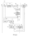
- the signal processor 110 comprises a subtracter 120, an orthogonal transformer 121, a quantizer 122, a dequantizer 123, an inverse orthogonal transformer 124 and an adder 125.
- the frame memory 111 is connected to a filter/rounding offset designing module 112 and a filter processor 113.
- the filter/rounding offset designing module 112 designs a filter coefficient and a rounding offset from the input image signal 101 and the local decoded image signal 104, and generates a filter coefficient 105 and a rounding offset 126.
- the filter processes 113 filters the local decoded image signal 104 using the filter coefficient 105 and the rounding offset 126, and generates an image signal 106.
- variable length encoder 115 performs variable length encoding on residual information 102, the filter coefficient 105 and the rounding offset 126, and outputs encoded data 109.
- the input image signal 101 is input to the signal processor 110.
- the signal processor 110 generates an residual signal between a prediction image signal 108 and the input image signal 101 (S11), and generates the residual information (for example, DCT coefficient) 102 obtained by orthogonal-transforming the residual signal (S12).
- the local decoded image signal 103 is generated from the prediction image signal 108 and the residual signal and is output (S13).
- the residual information 102 is input to the variable length encoder 115, and the local decoded image signal 103 is stored in the frame memory 111.
- the input image signal 101 is input to the signal processor 110.
- the input image signal 101 is input to the subtracter 120.
- the subtracter 120 generates a residual signal by calculating a difference between the input image signal 101 and the prediction image signal 108.
- the orthogonal transformer 121 orthogonal-transforms the residual signal 116 and generate a transform coefficient 117.
- the quantizer 122 quantizes the transform coefficient 117.
- the quantized transform coefficient is input to the variable length encoder as residual information 102, on one hand, and is dequantized with the dequantizer 123 and then subjected to inverse orthogonal transform with the inverse orthogonal transformer 124, on the other hand.
- the adder 125 adds the reconstructed residual signal 119 and the prediction image signal 108, and generates the local decoded image signal 103.
- the local decoded image signal 103 is stored in the frame memory 111.
- the local decoded image signal 104 read from the frame memory 111 is input to the filter/rounding offset designing module 112 and the filter processor 113.
- the filter/rounding offset designing module 112 designs a filter and a rounding offset from the input image signal 101 and the local decoded image signal 104 (S14).
- the filter/rounding offset designing module 112 sets a filter coefficient for use in a filtering process in the video decoding apparatus, and sets a rounding offset for controlling rounding of a filtering operation.
- the filter coefficient 105 and the rounding offset 126 are input to the filter processor 113 and the variable length encoder 115.
- the filter/rounding offset designing module 112 designs a filter
- the filtering process is done.
- the filter processor 113 filters the local decoded image signal 104 using the filter coefficient 105 and the rounding offset 126, and generates the image signal 106 (S15).
- the image signal 106 is stored in the frame memory 111.
- the image signal stored in the frame memory 111 is read as a reference image signal 107, and input to the predictor 114.
- the predictor 114 predicts using the reference image signal 107, and generates the prediction image signal 108 (S16).
- the prediction image signal 108 is input to the signal processor 110.
- the variable length encoder 115 performs variable length encoding on the residual information 102, the filter coefficient 105 and the rounding offset 126, and generates encoded data 109 including those codes (S17).
- the filter processor 113 carries out the filtering process according to the following equation.
- S flt (x,y) is a pixel value of position (x,y) of the image provided by the filtering process
- S(x,y) is a pixel value of position (x,y) of the local decoded image
- N is a predetermined natural number.
- ⁇ (int) D is integer values
- h i j (int) is the filter coefficient
- ⁇ (int) is the rounding offset
- D is a predetermined value.
- a division is assumed to be an integer division.
- the value set with the filter/rounding offset designing module 112 is input as hi j (int), ⁇ (int).
- the equation (1) means that the integer division is performed on a value obtained by adding the set rounding offset ⁇ (int) to the weighted sum of values of pixels located around a to-be-filtered pixel (x, y).
- the filter coefficient hi j (int) corresponds to the weight of the weighted sum.
- the filtering process is done using bit shift operation in terms of simple and easy of hardware realization and high-speed processing.
- the filter/rounding offset designing module 112 sets hi j (int), ⁇ (int) so that an error between the image provided by filtering and the input image decreases.
- a square error in units of a frame can be used as the error.
- S org (x,y) is a pixel of position (x, y) of the input image
- X, Y are a set of x coordinate and y coordinate in each frame.
- a method for solving a Wiener-Hopf equation is known as a method for obtaining a filter coefficient for minimizing a square error.
- the filter coefficient hi j (int) and the rounding offset ⁇ (int) are an integer value
- the filter coefficient hi j (int) and the rounding offset ⁇ (int) are obtained by an approximation procedure based on the above method.
- hij corresponds to an approximate value of hij (int) /D
- ⁇ corresponds to an approximate value of ( ⁇ (int) - D/2)/D.
- D/2 is a value for approximating the integer division to a floating-point divide.
- hi j, ⁇ for minimizing a square error between the input image provided by the filtering process and the input image is obtained by solving an equation established by setting a value obtained by differentiating partially the equation (5) by hij, ⁇ to 0. ⁇ x ⁇ X ⁇ y ⁇ Y s ⁇ flt x y - s org x y 2
- the filter coefficient hij (int) and the rounding offset ⁇ (int) may be calculated according to the following equation, for example.
- hij (int) and ⁇ (int) are calculated in units of a frame by the above described method, and output as the filter coefficient 105 and the rounding offset 126.
- an error between the output image provided with the video decoding apparatus and the input image can be decreased in comparison with a case of setting the rounding offset to a fixed value. Further, a prediction efficiency is improved because an error between the input image and the reference image can be decreased.
- This video decoding apparatus comprises a variable length decoder 210, a signal processor 211, a frame memory 212, a predictor 213 and a filter processor 214.
- the variable length decoder 210 decodes encoded data 201, and outputs residual information 202, a filter coefficient 209 and a rounding offset 208.
- the signal processor 211 reproduces a residual based on residual information 202, and generates a decoded image signal 203 from this residual and a prediction image signal 207 from the predictor 213.
- the frame memory 212 stores the decoded image signal 203.
- the predictor 213 generates a prediction image signal 207 from the image signal stored in the frame memory 212.
- the signal processor 211 comprises a dequantizer 217, an inverse orthogonal transformer 218 and an adder 219 as shown in FIG. 5 concretely.
- the dequantizer 217 dequantizes the residual information 202 and generates a transform coefficient 215.
- the inverse orthogonal transformer 218 subjects the transform coefficient 215 to inverse orthogonal transform, and generates a residual signal 216.
- the adder 219 adds the prediction image signal 207 and the residual signal 216, and generates a decoded image signal 203.
- the encoded data 109 is output, as the encoded data 201 to be decoded, from the video encoding apparatus of FIG. 1 of the first embodiment, and is input to the variable length decoder 210 through a storage system or a transmission system.
- the encoded data 201 to be decoded includes codes of residual information, a filter coefficient, information of a rounding offset.
- the variable length encoder 210 decodes each of these codes and outputs residual information 202, a filter coefficient 209, and an offset 208 (S21).
- the residual information 202 is input to the signal processor 211, and the filter coefficient 209 and the rounding offset 208 are input to the filter processor 214.
- the signal processor 211 reproduces a residual based on the residual information 202, and generates the decoded image signal 203 from the prediction image signal 207 and the reproduced residual (S22).
- the transform coefficient quantized as the residual information 202 is input to the dequantizer 217.
- the quantized transform coefficient is dequantized with the dequantizer 217, and then subjected to inverse orthogonal transform with the inverse orthogonal transformer 218, whereby a residual signal 216 is generated.
- the adder 219 adds the prediction image signal 207 to the residual signal 216, and provides the decoded image signal 203.
- the decoded image signal 203 is stored in the frame memory 212, and the decoded image signal 204 read from the frame memory 212 is input to the filter processor 214.
- the filter processor 214 filters the decoded image signal 204 using the filter coefficient 209 and the rounding offset 208 similarly to the filter processor 113 of the first embodiment, and generates an image signal 205 (S23).
- the image signal 205 is stored in the frame memory 212, and output as an output image signal.
- the image signal stored in the frame memory 212 is read as a reference image signal 206, and input to the predictor 213.
- the predictor 213 predicts using the reference image signal 206 and generates the prediction image signal 207.
- the prediction image signal 207 is input to the signal processor 211.
- an error between the input image encoded with the video encoding apparatus and the output image can be decreased in comparison with a case of setting the rounding offset to a fixed value. Further, prediction efficiency is improved because an error between the input image and the reference image can be decreased.
- the third embodiment of the present invention will be described referring to FIG. 7 .
- the basic configuration of the video encoding apparatus of the present embodiment is similar to the first embodiment. However, in the present embodiment, the filter processor 113 of FIG. 1 is not provided, and a predictor 310 generates a prediction image signal 305 using a local decoded image signal 303 as a reference image signal 304.
- the signal processor 308 when an input image signal 301 is input to a signal processor 308, the signal processor 308 generates a residual signal between the prediction image signal 305 and the input image signal 301, and generates residual information 302 by transforming the residual signal. Further, the signal processor 308 generates a local decoded image signal 303 from the prediction image signal 305 and the residual signal.
- the residual information 302 is input to the variable length encoder 311, and the local decoded image signal 303 is stored in the frame memory 309.
- the local decoded image signal 303 stored in the frame memory 309 is input to the predictor 310 as a reference image signal 304, and to the filter/rounding offset designing module 312.
- the filter/rounding offset designing module 312 designs a filter and a rounding offset from the input image signal 301 and the local decoded image signal 304.
- the filter/rounding offset designing module 312 sets the filter coefficient and rounding offset so that an error between an image obtained by filtering a decoded image in the video decoding apparatus and the input image decreases.
- the operation of the filter/rounding offset designing module 312 may be done similarly to the filter/rounding offset designing module 112 of the first embodiment.
- the filter coefficient 307 and the rounding offset 313 are input to the variable length encoder 311, and are encoded.
- an error between the output image provided with the video decoding apparatus and the input image can be decreased in comparison with a case of setting the rounding offset to a fixed value.
- the fourth embodiment will be described referring to FIG. 8 .
- the basic configuration of the video decoding apparatus of the present embodiment is similar to the second embodiment.
- the image signal 406 output from the filter processor 413 is not stored in the frame memory 411, and the predictor 412 generates a prediction image signal 405 using the decoded image signal 403 as a reference image signal 404.
- the variable length decoder 409 decodes the encoded data 401, and outputs residual information 402, a filter coefficient 408, and a rounding offset 407.
- the residual information 402 is input to the signal processor 410, and the filter coefficient 408 and the rounding offset 407 are input to the filter processor 413.
- the signal processor 410 reproduces a residual based on the residual information 402, and generates the decoded image signal 403 from the prediction image signal 405 of the predictor 412 and the reproduced residual.
- the decoded image signal 403 is stored in the frame memory 411.
- the decoded image signal 403 of the frame memory 411 is input to the predictor 412 as the reference image signal 404.
- the predictor 412 generates a prediction image signal 405 using this reference image signal 404.
- an error between the input image encoded with the video encoding apparatus and the output image can be decreased in comparison with a case of setting the rounding offset to a fixed value.
- the image encoding and decoding method and apparatus related to the present invention are employed for image compression processing in a communication media, a storage media and a broadcast media.
Landscapes
- Engineering & Computer Science (AREA)
- Multimedia (AREA)
- Signal Processing (AREA)
- Compression Or Coding Systems Of Tv Signals (AREA)
Abstract
Description
- The present invention relates to a video encoding apparatus for adding information for controlling a filtering process performed with a video decoding apparatus to encoded data, and a video decoding apparatus for performing a filtering process on a decoded image based on information for controlling the filtering process, which is added to encoded data-Backgrourd Art
- As a technique to output an image obtained by filtering a decoded image, there is a technique by which an encoding apparatus designs a filter to minimize an error between an input image and an image provided by filtering the decoded image and transmits information of this filter, and a decoding apparatus outputs an image obtained by filtering the decoded image using the filter information (S.Wittmann and T.Wedi, "Post-filter SEI message for 4:4:4 coding", JVT of ISO/IEC MPEG&ITU-T VCEG, JVT-S030, April 2006 (referred to as Wittmann)). This allows the decoding apparatus to provide an output image of a small error with respect to the input image.
- As a similar technique, there is considered a method of using an image obtained by filtering a decoded image as a reference image in generating a prediction image in addition to processing similar to Wittmann. This makes it possible to provide an effect to reduce a prediction error in predicting a next frame because an error between the reference image and the input image reduces.
- The above technique causes a rounding error when filtering is done by integer division. Accordingly, in order to reduce an error between an input image and an image provided by a filtering process using the integer division, it is necessary to control rounding as well as a filter coefficient according to the image. However, the rounding based on round-off used broadly cannot be controlled according to the image.
- As a technique to avoid accumulation of rounding errors in a filtering process, there is a technique of selecting round-up or round-down in the rounding for filtering (
JP-A 11-69362 - As described above, the prior art has a problem not to be able to control the rounding freely according to an image.
- It is an object of the present invention to provide a video encoding/decoding apparatus which decreases an error between an input image and a reference image, and an error between the input image and an output image by controlling rounding freely according to an image.
- An aspect of the present invention provides a video encoding apparatus comprising a setting module to set a filter coefficient for use in a filtering process in a video decoding apparatus, and set a rounding offset for controlling the rounding of operation in the filtering process, and an encoder to output information of the filter coefficient and the rounding offset as encoded data.
- Another aspect of the present invention provides a video decoding apparatus comprising an information acquisition module to acquire information of a filter coefficient and a rounding offset from encoded data, a signal processor to generate a decoded image signal from the encoded data, a filter processor to filter a decoded image of the decoded image signal by using the filter coefficient and the rounding offset obtained from the encoded data.
-
-
FIG. 1 is a block diagram illustrating a video encoding apparatus concerning the first embodiment. -
FIG. 2 is a block diagram illustrating a signal processor of the video encoding apparatus concerning the first embodiment. -
FIG. 3 is a flowchart illustrating an action of the video encoding apparatus concerning the first embodiment. -
FIG. 4 is a block diagram illustrating a video decoding apparatus concerning the second embodiment. -
FIG. 5 is a block diagram illustrating a signal processor of the video decoding apparatus concerning the second embodiment. -
FIG. 6 is a flowchart illustrating an action of the video decoding apparatus concerning the second embodiment. -
FIG. 7 is a block diagram illustrating a video encoding apparatus concerning the third embodiment. -
FIG. 8 is a block diagram illustrating a video decoding apparatus concerning the fourth embodiment. - Best Mode for Carrying Out the Invention There will now be explained embodiments of the present invention.
- Configuration of a video encoding apparatus concerning the first embodiment will be described referring to
FIG. 1 . Aninput image signal 101 is input to asignal processor 110. Thesignal processor 110 receives aprediction image signal 108 from apredictor 114, calculates a residual signal between thisprediction image signal 108 and theinput image signal 101, and generates a residual information by transforming this residual signal into a coefficient. Thesignal processor 110 also generates a local decodedimage signal 103 from theprediction image signal 108 and the residual signal. The local decoded image signal output terminal of thesignal processor 110 is connected to aframe memory 111, and its residual information output terminal is connected to avariable length encoder 115. Theframe memory 111 stores the local decodedimage signal 103. Thepredictor 114 generates a prediction image signal from the image signal stored in theframe memory 111. - Concretely, the
signal processor 110 comprises asubtracter 120, anorthogonal transformer 121, aquantizer 122, adequantizer 123, an inverseorthogonal transformer 124 and anadder 125. Theframe memory 111 is connected to a filter/roundingoffset designing module 112 and afilter processor 113. The filter/roundingoffset designing module 112 designs a filter coefficient and a rounding offset from theinput image signal 101 and the local decodedimage signal 104, and generates afilter coefficient 105 and arounding offset 126. The filter processes 113 filters the local decodedimage signal 104 using thefilter coefficient 105 and therounding offset 126, and generates animage signal 106. - The
variable length encoder 115 performs variable length encoding onresidual information 102, thefilter coefficient 105 and therounding offset 126, and outputs encodeddata 109. - Action of the video encoding apparatus of the above configuration will be described referring to the flowchart of
FIG. 3 . - The
input image signal 101 is input to thesignal processor 110. Thesignal processor 110 generates an residual signal between aprediction image signal 108 and the input image signal 101 (S11), and generates the residual information (for example, DCT coefficient) 102 obtained by orthogonal-transforming the residual signal (S12). The local decodedimage signal 103 is generated from theprediction image signal 108 and the residual signal and is output (S13). Theresidual information 102 is input to thevariable length encoder 115, and the local decodedimage signal 103 is stored in theframe memory 111. - There will now be described an example of the
signal processor 110 usingFIG. 2 . Theinput image signal 101 is input to thesignal processor 110. Theinput image signal 101 is input to thesubtracter 120. Thesubtracter 120 generates a residual signal by calculating a difference between theinput image signal 101 and theprediction image signal 108. Theorthogonal transformer 121 orthogonal-transforms theresidual signal 116 and generate atransform coefficient 117. Thequantizer 122 quantizes thetransform coefficient 117. The quantized transform coefficient is input to the variable length encoder asresidual information 102, on one hand, and is dequantized with thedequantizer 123 and then subjected to inverse orthogonal transform with the inverseorthogonal transformer 124, on the other hand. Theadder 125 adds the reconstructedresidual signal 119 and theprediction image signal 108, and generates the local decodedimage signal 103. The local decodedimage signal 103 is stored in theframe memory 111. - The local decoded
image signal 104 read from theframe memory 111 is input to the filter/roundingoffset designing module 112 and thefilter processor 113. The filter/roundingoffset designing module 112 designs a filter and a rounding offset from theinput image signal 101 and the local decoded image signal 104 (S14). In other words, the filter/roundingoffset designing module 112 sets a filter coefficient for use in a filtering process in the video decoding apparatus, and sets a rounding offset for controlling rounding of a filtering operation. Thefilter coefficient 105 and therounding offset 126 are input to thefilter processor 113 and thevariable length encoder 115. - When the filter/rounding
offset designing module 112 designs a filter, the filtering process is done. - In other words, the
filter processor 113 filters the localdecoded image signal 104 using thefilter coefficient 105 and therounding offset 126, and generates the image signal 106 (S15). - The
image signal 106 is stored in theframe memory 111. The image signal stored in theframe memory 111 is read as areference image signal 107, and input to thepredictor 114. Thepredictor 114 predicts using thereference image signal 107, and generates the prediction image signal 108 (S16). Theprediction image signal 108 is input to thesignal processor 110. Thevariable length encoder 115 performs variable length encoding on theresidual information 102, thefilter coefficient 105 and therounding offset 126, and generates encodeddata 109 including those codes (S17). - The
filter processor 113 carries out the filtering process according to the following equation.
where Sflt(x,y) is a pixel value of position (x,y) of the image provided by the filtering process, S(x,y) is a pixel value of position (x,y) of the local decoded image, and N is a predetermined natural number.
hij(int), δ(int), D is integer values, hi j (int) is the filter coefficient, δ(int) is the rounding offset, and D is a predetermined value. A division is assumed to be an integer division. - The value set with the filter/rounding offset designing
module 112 is input as hi j(int), δ(int). - The equation (1) means that the integer division is performed on a value obtained by adding the set rounding offset δ(int) to the weighted sum of values of pixels located around a to-be-filtered pixel (x, y).
- In addition, the filter coefficient hi j(int) corresponds to the weight of the weighted sum.
- In general, the filtering process is done using bit shift operation in terms of simple and easy of hardware realization and high-speed processing. When bit shift operation is used, assuming D=2n, the following equation is used.

- The filter/rounding offset designing
module 112 sets hi j(int), δ(int) so that an error between the image provided by filtering and the input image decreases. - For example, a square error in units of a frame can be used as the error.

where Sorg(x,y) is a pixel of position (x, y) of the input image, and X, Y are a set of x coordinate and y coordinate in each frame. A method for solving a Wiener-Hopf equation is known as a method for obtaining a filter coefficient for minimizing a square error. In the present embodiment, since there is a constraint that the filter coefficient hi j(int) and the rounding offset δ(int) are an integer value, the filter coefficient hi j(int) and the rounding offset δ(int) are obtained by an approximation procedure based on the above method. At first, the equation (1) is approximated to the following equation.
where hij corresponds to an approximate value of hij(int)/D, and δ corresponds to an approximate value of (δ(int) - D/2)/D. In addition, D/2 is a value for approximating the integer division to a floating-point divide. - When the equation (4) is used, hi j, δ for minimizing a square error between the input image provided by the filtering process and the input image is obtained by solving an equation established by setting a value obtained by differentiating partially the equation (5) by hij, δ to 0.

- In other words, the equation on hij, δ may be solved.


- Since hij is an approximate value of hij(int)/D and δ corresponds to an approximate value of (δ(int) - D/2)/D, the filter coefficient hij(int) and the rounding offset δ(int) may be calculated according to the following equation, for example.


hij(int) and δ(int) are calculated in units of a frame by the above described method, and output as thefilter coefficient 105 and the rounding offset 126. - In the present embodiment, since it is possible to control the rounding according to the image, an error between the output image provided with the video decoding apparatus and the input image can be decreased in comparison with a case of setting the rounding offset to a fixed value. Further, a prediction efficiency is improved because an error between the input image and the reference image can be decreased.
- A video decoding apparatus concerning the second embodiment of the present invention will be described referring to
FIG. 4 . This video decoding apparatus comprises avariable length decoder 210, asignal processor 211, aframe memory 212, apredictor 213 and afilter processor 214. Thevariable length decoder 210 decodes encodeddata 201, and outputsresidual information 202, afilter coefficient 209 and a rounding offset 208. Thesignal processor 211 reproduces a residual based onresidual information 202, and generates a decodedimage signal 203 from this residual and aprediction image signal 207 from thepredictor 213. Theframe memory 212 stores the decodedimage signal 203. Thepredictor 213 generates aprediction image signal 207 from the image signal stored in theframe memory 212. - The
signal processor 211 comprises adequantizer 217, an inverseorthogonal transformer 218 and anadder 219 as shown inFIG. 5 concretely. Thedequantizer 217 dequantizes theresidual information 202 and generates atransform coefficient 215. The inverseorthogonal transformer 218 subjects thetransform coefficient 215 to inverse orthogonal transform, and generates aresidual signal 216. Theadder 219 adds theprediction image signal 207 and theresidual signal 216, and generates a decodedimage signal 203. - Action of the video encoding apparatus of the above configuration will be described referring to the flowchart of
FIG. 6 . - The encoded
data 109 is output, as the encodeddata 201 to be decoded, from the video encoding apparatus ofFIG. 1 of the first embodiment, and is input to thevariable length decoder 210 through a storage system or a transmission system. The encodeddata 201 to be decoded includes codes of residual information, a filter coefficient, information of a rounding offset. Thevariable length encoder 210 decodes each of these codes and outputsresidual information 202, afilter coefficient 209, and an offset 208 (S21). Theresidual information 202 is input to thesignal processor 211, and thefilter coefficient 209 and the rounding offset 208 are input to thefilter processor 214. Thesignal processor 211 reproduces a residual based on theresidual information 202, and generates the decodedimage signal 203 from theprediction image signal 207 and the reproduced residual (S22). - There will now be described an example of the
signal processor 211 referring toFIG. 4 . It is assumed that the encoded data is generated with the encoding apparatus of the first embodiment that has theimage signal processor 110 explained referring toFIG. 2 . The transform coefficient quantized as theresidual information 202 is input to thedequantizer 217. The quantized transform coefficient is dequantized with thedequantizer 217, and then subjected to inverse orthogonal transform with the inverseorthogonal transformer 218, whereby aresidual signal 216 is generated. Theadder 219 adds theprediction image signal 207 to theresidual signal 216, and provides the decodedimage signal 203. - The decoded
image signal 203 is stored in theframe memory 212, and the decodedimage signal 204 read from theframe memory 212 is input to thefilter processor 214. Thefilter processor 214 filters the decodedimage signal 204 using thefilter coefficient 209 and the rounding offset 208 similarly to thefilter processor 113 of the first embodiment, and generates an image signal 205 (S23). Theimage signal 205 is stored in theframe memory 212, and output as an output image signal. The image signal stored in theframe memory 212 is read as areference image signal 206, and input to thepredictor 213. Thepredictor 213 predicts using thereference image signal 206 and generates theprediction image signal 207. Theprediction image signal 207 is input to thesignal processor 211. - In the present embodiment, since it is possible to control the rounding according to the image, an error between the input image encoded with the video encoding apparatus and the output image can be decreased in comparison with a case of setting the rounding offset to a fixed value. Further, prediction efficiency is improved because an error between the input image and the reference image can be decreased.
- The third embodiment of the present invention will be described referring to
FIG. 7 . The basic configuration of the video encoding apparatus of the present embodiment is similar to the first embodiment. However, in the present embodiment, thefilter processor 113 ofFIG. 1 is not provided, and apredictor 310 generates aprediction image signal 305 using a local decodedimage signal 303 as areference image signal 304. - In other words, according to the video encoding apparatus of
FIG. 7 , when aninput image signal 301 is input to asignal processor 308, thesignal processor 308 generates a residual signal between theprediction image signal 305 and theinput image signal 301, and generatesresidual information 302 by transforming the residual signal. Further, thesignal processor 308 generates a local decodedimage signal 303 from theprediction image signal 305 and the residual signal. Theresidual information 302 is input to thevariable length encoder 311, and the local decodedimage signal 303 is stored in theframe memory 309. - The local decoded
image signal 303 stored in theframe memory 309 is input to thepredictor 310 as areference image signal 304, and to the filter/rounding offset designingmodule 312. The filter/rounding offset designingmodule 312 designs a filter and a rounding offset from theinput image signal 301 and the local decodedimage signal 304. At this time, the filter/rounding offset designingmodule 312 sets the filter coefficient and rounding offset so that an error between an image obtained by filtering a decoded image in the video decoding apparatus and the input image decreases. The operation of the filter/rounding offset designingmodule 312 may be done similarly to the filter/rounding offset designingmodule 112 of the first embodiment. Thefilter coefficient 307 and the rounding offset 313 are input to thevariable length encoder 311, and are encoded. - In the present embodiment, since it is possible to control the rounding according to the image, an error between the output image provided with the video decoding apparatus and the input image can be decreased in comparison with a case of setting the rounding offset to a fixed value.
- The fourth embodiment will be described referring to
FIG. 8 . The basic configuration of the video decoding apparatus of the present embodiment is similar to the second embodiment. However, theimage signal 406 output from thefilter processor 413 is not stored in theframe memory 411, and thepredictor 412 generates aprediction image signal 405 using the decodedimage signal 403 as areference image signal 404. - In other words, according to the video decoding apparatus of
FIG. 8 , when the encodeddata 401 is input to thevariable length decoder 409, thevariable length decoder 409 decodes the encodeddata 401, and outputsresidual information 402, afilter coefficient 408, and a rounding offset 407. Theresidual information 402 is input to thesignal processor 410, and thefilter coefficient 408 and the rounding offset 407 are input to thefilter processor 413. Thesignal processor 410 reproduces a residual based on theresidual information 402, and generates the decodedimage signal 403 from theprediction image signal 405 of thepredictor 412 and the reproduced residual. The decodedimage signal 403 is stored in theframe memory 411. The decodedimage signal 403 of theframe memory 411 is input to thepredictor 412 as thereference image signal 404. Thepredictor 412 generates aprediction image signal 405 using thisreference image signal 404. - In the present embodiment, since it is possible to control the rounding according to the image, an error between the input image encoded with the video encoding apparatus and the output image can be decreased in comparison with a case of setting the rounding offset to a fixed value.
- According to the present invention, it is possible to decrease an error between the input image and the reference image, and an error between the input image and the output image, by controlling the rounding according to the image freely.
- It is possible to make a computer execute the procedure described in the present embodiments. Alternatively, it is possible to distribute the procedure by storing it in a storing medium such as magnetic disks (flexible disk, hard disk, etc.), optical disks (CD-ROM, DVD, etc.), semiconductor memories as a program allowing a computer execute the procedure.
- The image encoding and decoding method and apparatus related to the present invention are employed for image compression processing in a communication media, a storage media and a broadcast media.
Claims (9)
- A video encoding apparatus comprising:a setting module to set a filter coefficient for use in a filtering process in a video decoding apparatus, and to set a rounding offset for controlling rounding of operation in the filtering process; andan encoder to output the filter coefficient and information of the rounding offset as encoded data.
- The video encoding apparatus according to claim 1, further comprising:a signal processor to subject an input image signal and a prediction image signal to signal processing, and to generate a local decoded image;a filter processor to filter the local decoded image using the filter coefficient and the rounding offset that are set for the filtering process in the video decoding apparatus;an image storage to store an image provided by the filtering process as a reference image; anda predictor to generate a prediction image signal using the stored image.
- The video encoding apparatus according to claim 2, wherein the filter processor carries out the filtering process by performing integer division on a value obtained by adding the rounding offset to a weighting sum of values of pixels located around a to-be-filtered pixel on the local decoded image.
- The video encoding apparatus according to claim 3, wherein the signal processor generates residual information by performing signal processing on the input image signal and the prediction image signal, and the encoder outputs the encoded data by encoding the residual information together with the filter coefficient and the information of the rounding offset.
- The video encoding apparatus according to claim 4, wherein the setting module sets the rounding offset so that an error between an image provided by the filtering process and the input image decreases.
- The video encoding apparatus according to claim 5, wherein the setting module obtains the filter coefficient and the rounding offset using the input image signal and the local decoded signal.
- The video decoding apparatus comprising:an information acquisition module to acquire information of a filter coefficient and a rounding offset from encoded data;a signal processor to generate a decoded image signal from the encoded data; anda filter processor to filter a decoded image of the decoded image signal using the filter coefficient and the rounding offset acquired from the encoded data.
- The video decoding apparatus according to claim 7, comprising a storage to store the image obtained by the filtering process as a reference image, and a predictor to generate the prediction image signal using the stored image, wherein the signal processor generates the decoded image signal using the encoded data and the prediction image signal.
- The video decoding apparatus according to claim 8, wherein the filter processor carries out the filtering process by performing integer division on a value obtained by adding the rounding offset to a weighting sum of values of pixels located around a to-be-filtered pixel on a decoded image.
Applications Claiming Priority (2)
| Application Number | Priority Date | Filing Date | Title |
|---|---|---|---|
| JP2008119151 | 2008-04-30 | ||
| PCT/JP2009/058513 WO2009133938A1 (en) | 2008-04-30 | 2009-04-30 | Time-varying image encoding and decoding device |
Publications (2)
| Publication Number | Publication Date |
|---|---|
| EP2271113A1 true EP2271113A1 (en) | 2011-01-05 |
| EP2271113A4 EP2271113A4 (en) | 2011-10-26 |
Family
ID=41255153
Family Applications (1)
| Application Number | Title | Priority Date | Filing Date |
|---|---|---|---|
| EP09738875A Withdrawn EP2271113A4 (en) | 2008-04-30 | 2009-04-30 | Time-varying image encoding and decoding device |
Country Status (11)
| Country | Link |
|---|---|
| US (1) | US20100329335A1 (en) |
| EP (1) | EP2271113A4 (en) |
| JP (1) | JPWO2009133938A1 (en) |
| KR (1) | KR20100111732A (en) |
| CN (1) | CN101960857A (en) |
| AU (1) | AU2009240883A1 (en) |
| BR (1) | BRPI0909151A2 (en) |
| CA (1) | CA2718341A1 (en) |
| MX (1) | MX2010009616A (en) |
| RU (1) | RU2010137683A (en) |
| WO (1) | WO2009133938A1 (en) |
Families Citing this family (1)
| Publication number | Priority date | Publication date | Assignee | Title |
|---|---|---|---|---|
| AU2010331511B2 (en) * | 2009-12-18 | 2015-01-15 | Sharp Kabushiki Kaisha | Image filter, encoding device, decoding device, and data structure |
Family Cites Families (8)
| Publication number | Priority date | Publication date | Assignee | Title |
|---|---|---|---|---|
| US6091775A (en) * | 1997-04-17 | 2000-07-18 | Sharp Kabushiki Kaisha | Video-coding device and video-decoding device |
| JP2998741B2 (en) * | 1997-06-09 | 2000-01-11 | 株式会社日立製作所 | Moving picture encoding method, computer-readable recording medium on which the method is recorded, and moving picture encoding apparatus |
| JP2001275110A (en) * | 2000-03-24 | 2001-10-05 | Matsushita Electric Ind Co Ltd | Method and apparatus for dynamic loop and post-filtering |
| IL164176A0 (en) * | 2002-04-23 | 2005-12-18 | Nokia Corp | Method and device for indicating quantizer parameters in a video coding system |
| US20040179610A1 (en) * | 2003-02-21 | 2004-09-16 | Jiuhuai Lu | Apparatus and method employing a configurable reference and loop filter for efficient video coding |
| JP4284265B2 (en) * | 2004-11-02 | 2009-06-24 | 株式会社東芝 | Moving picture coding apparatus, moving picture coding method, moving picture decoding apparatus, and moving picture decoding method |
| JP2006211152A (en) * | 2005-01-26 | 2006-08-10 | Hokkaido Univ | Image encoding device, image decoding device, image encoding method, image decoding method, image encoding program, image decoding program |
| EP2041981B1 (en) * | 2006-07-18 | 2013-09-04 | Thomson Licensing | Methods and apparatus for adaptive reference filtering |
-
2009
- 2009-04-30 EP EP09738875A patent/EP2271113A4/en not_active Withdrawn
- 2009-04-30 MX MX2010009616A patent/MX2010009616A/en not_active Application Discontinuation
- 2009-04-30 AU AU2009240883A patent/AU2009240883A1/en not_active Abandoned
- 2009-04-30 JP JP2010510167A patent/JPWO2009133938A1/en active Pending
- 2009-04-30 CA CA2718341A patent/CA2718341A1/en not_active Abandoned
- 2009-04-30 CN CN200980107229.2A patent/CN101960857A/en active Pending
- 2009-04-30 BR BRPI0909151A patent/BRPI0909151A2/en not_active IP Right Cessation
- 2009-04-30 WO PCT/JP2009/058513 patent/WO2009133938A1/en not_active Ceased
- 2009-04-30 RU RU2010137683/07A patent/RU2010137683A/en not_active Application Discontinuation
- 2009-04-30 KR KR1020107018994A patent/KR20100111732A/en not_active Ceased
-
2010
- 2010-09-13 US US12/880,918 patent/US20100329335A1/en not_active Abandoned
Also Published As
| Publication number | Publication date |
|---|---|
| AU2009240883A1 (en) | 2009-11-05 |
| CN101960857A (en) | 2011-01-26 |
| RU2010137683A (en) | 2012-06-10 |
| JPWO2009133938A1 (en) | 2011-09-01 |
| EP2271113A4 (en) | 2011-10-26 |
| US20100329335A1 (en) | 2010-12-30 |
| MX2010009616A (en) | 2010-09-30 |
| WO2009133938A1 (en) | 2009-11-05 |
| BRPI0909151A2 (en) | 2018-02-06 |
| CA2718341A1 (en) | 2009-11-05 |
| KR20100111732A (en) | 2010-10-15 |
Similar Documents
| Publication | Publication Date | Title |
|---|---|---|
| US8126053B2 (en) | Image encoding/decoding method and apparatus | |
| US8208543B2 (en) | Quantization and differential coding of alpha image data | |
| JP5590133B2 (en) | Moving picture coding apparatus, moving picture coding method, moving picture coding computer program, moving picture decoding apparatus, moving picture decoding method, and moving picture decoding computer program | |
| EP2153655B1 (en) | Method and apparatus for encoding and decoding image using modification of residual block | |
| US20230052841A1 (en) | Video decoder with reduced dynamic range transform with inverse transform shifting memory | |
| EP2843950A1 (en) | Method for image interpolation using asymmetric interpolation filter and apparatus therefor | |
| EP1788820A2 (en) | Image encoding method and apparatus and image decoding method and apparatus using characteristics of the human visual system | |
| US9877025B2 (en) | Video encoding and decoding with prediction at higher precision | |
| US20080247464A1 (en) | Method and apparatus for encoding and decoding based on intra prediction using differential equation | |
| KR101834819B1 (en) | Apparatus and method for encoding and decoding based region | |
| US20120177299A1 (en) | Image coding device and image decoding device | |
| US20120307889A1 (en) | Video decoder with dynamic range adjustments | |
| EP2001238A2 (en) | Image coding based on the Radon transform | |
| US7634148B2 (en) | Image signal transforming and inverse-transforming method and computer program product with pre-encoding filtering features | |
| US20080107176A1 (en) | Method and Apparatus for Detecting All Zero Coefficients | |
| US20090067737A1 (en) | Coding apparatus, coding method, decoding apparatus, decoding method, and program | |
| US9854242B2 (en) | Video decoder with reduced dynamic range transform with inverse transform clipping | |
| US20120230395A1 (en) | Video decoder with reduced dynamic range transform with quantization matricies | |
| US20100329335A1 (en) | Video encoding and decoding apparatus | |
| KR20240116835A (en) | Method and apparatus for improving the coding of side information required for coding a higher order ambisonics representation of a sound field | |
| US20080107183A1 (en) | Method and apparatus for detecting zero coefficients | |
| US20120183048A1 (en) | Video decoder with reduced dynamic range transform with multiple clipping | |
| US20120183044A1 (en) | Video decoder with reduced dynamic range transform with memory storing | |
| WO2021078653A1 (en) | Weighted psnr quality metric for video coded data | |
| JP2005535263A (en) | Method for transmitting data in an encoder |
Legal Events
| Date | Code | Title | Description |
|---|---|---|---|
| PUAI | Public reference made under article 153(3) epc to a published international application that has entered the european phase |
Free format text: ORIGINAL CODE: 0009012 |
|
| 17P | Request for examination filed |
Effective date: 20100831 |
|
| AK | Designated contracting states |
Kind code of ref document: A1 Designated state(s): AT BE BG CH CY CZ DE DK EE ES FI FR GB GR HR HU IE IS IT LI LT LU LV MC MK MT NL NO PL PT RO SE SI SK TR |
|
| AX | Request for extension of the european patent |
Extension state: AL BA RS |
|
| RIN1 | Information on inventor provided before grant (corrected) |
Inventor name: CHUJOH, TAKESHI Inventor name: YASUDA, GOKI |
|
| DAX | Request for extension of the european patent (deleted) | ||
| A4 | Supplementary search report drawn up and despatched |
Effective date: 20110922 |
|
| RIC1 | Information provided on ipc code assigned before grant |
Ipc: H04N 7/50 20060101ALI20110916BHEP Ipc: H04N 7/26 20060101ALI20110916BHEP Ipc: H04N 7/32 20060101AFI20110916BHEP |
|
| STAA | Information on the status of an ep patent application or granted ep patent |
Free format text: STATUS: THE APPLICATION IS DEEMED TO BE WITHDRAWN |
|
| 18D | Application deemed to be withdrawn |
Effective date: 20120424 |