EP2271028A1 - Topology abstraction method, topology abstraction apparatus and route controller - Google Patents
Topology abstraction method, topology abstraction apparatus and route controller Download PDFInfo
- Publication number
- EP2271028A1 EP2271028A1 EP08733944A EP08733944A EP2271028A1 EP 2271028 A1 EP2271028 A1 EP 2271028A1 EP 08733944 A EP08733944 A EP 08733944A EP 08733944 A EP08733944 A EP 08733944A EP 2271028 A1 EP2271028 A1 EP 2271028A1
- Authority
- EP
- European Patent Office
- Prior art keywords
- topology
- shuffle
- aggregation
- directional
- net
- Prior art date
- Legal status (The legal status is an assumption and is not a legal conclusion. Google has not performed a legal analysis and makes no representation as to the accuracy of the status listed.)
- Withdrawn
Links
Images



Classifications
-
- H—ELECTRICITY
- H04—ELECTRIC COMMUNICATION TECHNIQUE
- H04L—TRANSMISSION OF DIGITAL INFORMATION, e.g. TELEGRAPHIC COMMUNICATION
- H04L45/00—Routing or path finding of packets in data switching networks
- H04L45/02—Topology update or discovery
- H04L45/08—Learning-based routing, e.g. using neural networks or artificial intelligence
-
- H—ELECTRICITY
- H04—ELECTRIC COMMUNICATION TECHNIQUE
- H04L—TRANSMISSION OF DIGITAL INFORMATION, e.g. TELEGRAPHIC COMMUNICATION
- H04L45/00—Routing or path finding of packets in data switching networks
- H04L45/02—Topology update or discovery
Definitions
- the present invention relates to the network technology, and more particularly, to a method and an apparatus for topology aggregation and a routing controller.
- IP IP
- ATM Asynchronous Transmission Mode
- ASON Automatic Switched Optical Network
- each routing domain can be advertised to other routing domains in the network only after being aggregated by means of some topology aggregation method.
- each routing domain only maintains its own detailed topology information as well as aggregated topology information of other routing domains, thereby reducing the amount of information needing to be advertised and stored in the network.
- a topology aggregation process includes firstly constructing a full-mesh topology composed of border nodes based on a real topology, and further compressing, which is optional, the full-mesh topology into a sparser topology, such as a star topology, a tree topology and the like.
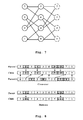
- Fig. 1 shows an example of a topology aggregation process.
- topology 100 is a real topology comprising eight nodes 1-8, ten links, and two working wavelengths ⁇ 1 and ⁇ 2 .
- the Nodes 1-4 are border nodes connected to external peer domains
- the Nodes 5-8 are internal nodes
- the solid line/the dashed line between nodes indicates the wavelength ⁇ 1 / ⁇ 2 path of the link is free and a new connection can be established.
- topology aggregation internal nodes of topology 100 are concealed, and only border nodes 1-4 and resource availability therebetween are reserved.
- the connectivity relation among these four border nodes can be represented by a connectivity matrix as shown in formula (1).
- Matrix ⁇ 1 - 0 1 1 0 - 0 0 1 0 - 1 1 0 1 -
- Matrix ⁇ 2 - 1 1 0 1 - 1 0 1 1 - 0 0 0 0 -
- Topology 101 shown in Fig. 1 has 4 border nodes 1-4, and thus the connectivity among border nodes can be represented by a 4 ⁇ 4 matrix for each wavelength ⁇ 1 and ⁇ 2 . If there is a logical link enabling two border nodes to be connected (for example, node 1 and node 4 can be connected with each other through wavelength ⁇ 1 path 1-5-6-3-4), the corresponding element of the matrix is set to 1, and 0 otherwise.
- Topology 101 which includes only border nodes 1-4, is a full-mesh topology constructed in accordance with the connectivity matrix. It can be seen that the number of links is reduced to 5 after the full-mesh topology construction (in the worst case, the number of links is 6, i.e., all nodes are connected).
- Topology 102 is the resultant topology after further compressing the topology 101.
- the redundant logical links in the former topology 101 are deleted, for example, the logical link of wavelength ⁇ 1 between node 3 and node 4 is replaced with the path 3-1-4, and the logical link of wavelength ⁇ 2 between node 2 and node 3 is replaced with the path 2-1-3. After compressing, the total number of links is further reduced to 3.
- the existing topology aggregation technology is designed for the ATM network.
- the main idea of the symmetric-node approach is that all border nodes of the real topology are merged into a single virtual node and the connection property between border nodes is represented by a certain common value.
- the advantage of this approach is that only a very little amount of information needs to be exchanged.
- the disadvantage is that the provided information is too rough and inaccurate excessively, which will cause that the intra-domain resources can't be utilized appropriately.
- the full-mesh approach aims at the accuracy of the aggregation information.
- topology aggregation methods designed for the ATM network are applied to the optical network, these methods will be too rough and inaccurate to reach a good performance as a condition of wavelength continuity constraint needs to be met. Therefore, a more suitable solution for topology aggregation is required for the optical network such as ASON.
- a method for topology aggregation comprising:
- an apparatus for topology aggregation comprising:
- a routing controller comprising:
- More link information for routing decision and more accurate topology can be provided according the present invention.
- Fig. 2 shows a flow chart of a method for topology aggregation according to an embodiment of the present invention.
- the topology aggregation is directed to one domain in AOSN.
- each link can support one or more of wavelengths ⁇ 1 , ⁇ 2 ,..., ⁇ w , n is the total number of nodes, and m is the total number of links, and W is the total number of wavelengths.
- G R can be a multi-graph wherein there are multiple optical fiber links between two nodes.
- the link-diversity path number c ( i,j, ⁇ k ) between each pair of border nodes is obtained from the adjacent matrix R ⁇ k .
- the term "link-diversity path” used herein indicates a path without any shared links between two border nodes.
- computing the link-diversity path number between two border nodes is turned into computing maximum flow between two border nodes, as the link-diversity path number between two border nodes equals to the maximum flow between a source and a destination in the canal network.
- the link-diversity path number between two border nodes is computed by calculating the maximum flow between them by utilizing a maximum flow algorithm.
- the maximum flow between two border nodes is calculated by utilizing the existing highest-label-preflow-push algorithm. In an alternative embodiment, the maximum flow between two border nodes is calculated using the Augmenting Path Algorithm.
- the connectivity matrix C is obtained by using the link-diversity path number c ( i , j , ⁇ k ) and a corresponding full-mesh topology G B is constructed.
- C c i j ⁇ k N ⁇ N ⁇ W
- G B V B E B
- M N ( N -1)/2
- V B ⁇ v 1 , v 2 ,..., v N ⁇
- E B ⁇ e 1 , e 2 ,..., e M ⁇
- e ( i, j, ⁇ k ) c ( i, j, ⁇ k ) .
- the connectivity matrix C of the present invention is different from the conventional one shown in formula (1). Instead of being represented by 0 and 1, the connectivity matrix of the present invention is represented by the link-diversity path number between two border nodes.
- the connectivity matrix C is represented by the link-diversity path number between two border nodes.
- the resulting full-mesh topology is further compressed to obtain a sparser topology so that the amount of information to be exchanged among domains is further reduced.
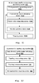
- Fig. 3 shows a flow chart of a topology compression process according to an embodiment of the present invention.
- a bi-directional shuffle-net construction is performed to obtain a bi-directional shuffle-net topology in which all nodes are null.
- each node in each column has P direct links to nodes in the next column, and the nodes in the last column also link to the nodes in first column so that a cylinder topology is formed.
- the bi-directional shuffle-net topology is an extended version of the shuffle-net.
- the bi-directional shuffle-net topology is different from the conventional shuffle-net topology in that its links are all bi-directional, that is to say, each node in each column not only has P links to nodes in the next column, but has P links to nodes in the previous column.
- parameters K and P of the bi-directional shuffle-net topology are computed for the full-mesh topology, wherein K and P can be solved by the following formula: Max K - 1 ⁇ P K - 1 , K ⁇ P - 1 K ⁇ N ⁇ KP K K , P ⁇ 2 wherein N is the number of nodes in the full-mesh topology, i.e., the number of border nodes in the real topology.
- the nodes in the full-mesh topology are mapped to nodes in the shuffle-net by means of a certain mapping relation, and corresponding logical link attributes are imparted to the bi-directional links in the shuffle-net.
- Fig. 6 shows a flow chart of a process of optimizing a bi-direction shuffle-net topology according to an embodiment of the present invention.
- the Genetic Algorithm (GA) is used for optimizing the bi-direction shuffle-net topology.
- the first generation P0 of the bi-direction shuffle-net topology is first obtained, which includes several chromosomes that can represent the way by which the nodes of the full-mesh topology are arranged in the bi-direction shuffle-net topology.
- the one-dimensional literal permutation encoding is used to construct the chromosomes.
- node 8 is a virtual node that is filled for making up the deficiency
- node 7 in the full-mesh topology corresponds to the node (0, 0) in the bi-directional shuffle-net
- node 2 corresponds to the node (1, 0)
- ..,node 4 corresponds to the node (2, 1)
- virtual node 8 corresponds to the node (3, 1), as shown in fig. 7 .
- the chromosomes in the present invention are different from those ordinarily composed of 0-1 bit sequence.
- the present invention utilizes the one-dimensional literal permutation encoding, wherein each gene is the node number. Therefore, mutation operation on chromosomes of the present invention is position-based, which usually changes the position of genes in the chromosomes, thus it is ensured that the next generation can inherit most characteristics from their parents and compatible genes can be reserved.
- step 620 after all nodes V B of the full-mesh topology G B is mapped into nodes V' of the bi-direction shuffle-net topology G' in accordance with each chromosome p, the mapping of logical links can be performed according to the node positions.
- node 7 is connected to node 4, 5, and 6, thus the bi-directional logical links (4,7), (5,7),(6,7) are reserved, and other logical links connected with node 7 are all deleted.
- Node 8 is a virtual node and doesn't participate in the mapping of logical links.
- C ⁇ c ⁇ i j ⁇ k N ⁇ N ⁇ W
- the connectivity matrix C' can be obtained in a manner similar to obtain the connectivity matrix C.
- the fitness value represents the degree of approximation between the connectivity matrix of the full-mesh topology and the connectivity matrix of the topology of the chromosome, the value of which is the opposite of the sum of the degree of deviation.
- the minus indicates that the smaller the deviation value is, the larger the fitness value is.
- the deviation value can be the absolute value of the ratio of the difference to the sum between the connectivity matrix of the topology of the chromosome and the target connectivity matrix. In an alternative embodiment, the deviation value is the absolute value of the difference between the connectivity matrix of the topology of the chromosome and the target connectivity matrix.
- step 640 genetic operation is performed based on the obtained fitness value to obtain chromosomes of the next generation.
- a selection operation is first performed on the chromosomes of the current generation based on the obtained fitness value to obtain the chromosomes for propagating the next generation. That is to say, the chromosome with a lower fitness value (for example, a fitness value lower than a threshold) is culled out, and only the chromosome with a higher fitness value is selected into the next generation.
- Cross-over and mutation operations are performed on the selected chromosomes to obtain the chromosomes of the next generation.
- Fig. 8 shows an example of crossover and mutation operations according to an embodiment of the present invention. It should be appreciated that the present invention is not limited to the crossover and mutation operations shown in Fig. 8 .
- step 650 it is determined whether the number of the iteration reaches a predetermined threshold or not. If the answer is yes, the resulting chromosome with the best fitness is taken as the optimization result at step 660, that is to say, the optimized bi-directional shuffle-net topology is obtained. If the answer is no, the process proceeds to step 620, and continues the iteration.
- the genetic operations are terminated if the fitness value of a chromosome reaches a predetermined threshold before the predetermined threshold for the number of the iteration is reached, and the bi-directional shuffle-net topology where the nodes are arranged and connected in accordance with the obtained chromosome, is taken as the resulting topology.
- the number of iteration can be determined based on need. The more the number of iteration is, the better the obtained result is, but more time is required to compute.
- the inventor has verified that the average deviation of each generation decreases quickly in the initial phase and reaches to a stable value after about 20 generations. After that, the average deviation fluctuates in a certain range.
- the average deviation after 30 generations is substantially smaller than 20 % , and the optimal individual deviation is substantially about 10%. It can be seen that the topology aggregation method of the present invention can achieve a more accurate topology and thus can provide more accurate and abundant information for routing decision, and thus can improve the performance.
- the topology aggregation method of the present invention provides detailed link information suitable for the optical network. More particularly, by employing the genetic algorithm to optimize the bi-directional shuffle-net topology, the more accurate topology structure is described using less logical links, and thus the performance is improved.
- the nodes with more link-diversity path number in the full-mesh topology are mapped into nodes connected directly in a shuffle-net topology using the obtained connectivity matrix of the full-mesh topology, thereby compressing the full-mesh topology into a bi-directional shuffle-net topology using the heuristic approach.
- the full-mesh topology is compressed into a symmetric-star topology by utilizing the obtained connectivity matrix of the full-mesh topology.
- the re-aggregation can be performed based on a predetermined time interval.
- a re-aggregation time interval is predetermined, and the re-aggregation can be performed periodically based on the predetermined time interval, regardless of the bandwidth change conditions of links in the intra-domain.
- an event-based re-aggregation policy is adopted, that is to say, the re-aggregation is performed only when a predetermined event occurs.
- a lazy re-aggregation policy can be used, i.e., the re-aggregation is performed only when a big topology change happens or the connection rejection rate reaches a predetermined threshold.
- the re-aggregation is performed when a predetermined connection rejection rate is reached.
- the re-aggregation is performed immediately when the connection rejection rate r exceeds a predetermined threshold ⁇ , wherein ⁇ is a constant based on customer's QoS requirement, for example is 20%.
- the re-aggregation is performed when the topology changes greatly.
- the link capacity is B channels
- the number of available channels at time t is c t .
- the predetermined value sequence b k has more elements so that topology re-aggregation occurs at a lower frequency when there are more available channels and occurs at a higher frequency when there are less available channels.
- the foregoing formula is just an example, and other methods can be used to obtain the predetermined value sequence b k .
- the re-aggregation is preformed only when a big topology change occurs, and is not preformed when the topology change is small. Therefore, in the case of ensuring that aggregation topology is updated in time, the number of re-aggregation is reduced, thereby reducing the consumed resources due to the implementation of re-aggregation and improving the performance.
- the present invention constructs the connectivity matrix by utilizing "link-diversity path number", which provides not only the availability information on available wavelengths but also the resource abundance information on wavelengths, thereby more detailed link information is provided for the routing decision to optimize the source allocation and thus improve the network performance.
- the obtained full-mesh topology is further compressed, thereby reducing the amount of information to be exchanged among domains and further improving the performance.
- the full-mesh topology is compressed into a bi-directional shuffle-net topology to reduce the number of links significantly, thereby reducing the amount of routing information needing to be exchanged among domains and improving the performance.
- the re-aggregation is performed by utilizing an event-based lazy re-aggregation policy, thereby reducing the consumed resources due to the implementation of re-aggregation and improving the performance.
- Fig. 9 shows an apparatus 900 for topology aggregation according to an embodiment of the present invention.
- the apparatus 900 for topology aggregation includes: link-diversity path number obtaining means 910 configured to obtain the link-diversity path number c ( i, j, ⁇ k ) between each pair of border nodes in a real topology; and topology constructing means 920 configured to obtain a connectivity matrix C by using the link-diversity path number c ( i, j, ⁇ k ) and construct a corresponding full-mesh topology G B .
- the link-diversity path number obtaining means 910 can operate in accordance with the above description with respect to steps 210-230 : an adjacent matrix is first computed from the real topology of a domain, and then the link-diversity path number between border nodes is obtained by calculating the maximum flow between border nodes.
- the highest-label-preflow-push algorithm, the Augmenting Path Algorithm, and other algorithms known to the skilled in the art can be used when computing the link-diversity path number.
- the topology constructing means 920 can operate in accordance with the above description with respect to step 240 : the connectivity matrix is constructed using the link-diversity path number obtained by the link-diversity path number obtaining means 910.
- the apparatus 900 for topology aggregation of the present invention constructs the connectivity matrix using the link-diversity path number, which provides not only the information on available wavelengths but also the resource information on the abundance degree of wavelengths, thereby facilitating the route selection and improving the performance.
- the apparatus 900 for topology aggregation further includes topology compressing means 930 configured to compress the full-mesh topology, thereby further reducing the amount of information to be exchanged among domains.
- the topology compressing means 930 includes: bi-directional shuffle-net topology constructing means 932 configured to initialize a bi-directional shuffle-net topology using determined structural parameters of the bi-directional shuffle-net topology; and bi-directional shuffle-net topology optimizing means 934 configured to optimize the bi-directional shuffle-net topology using the connectivity matrix of the full-mesh topology.
- the bi-directional shuffle-net topology optimizing means 934 can further optimize the bi-directional shuffle-net topology based on the genetic algorithm.
- Fig. 11 shows an embodiment of the bi-directional shuffle-net topology optimizing means 934 based on the genetic algorithm.
- the bi-directional shuffle-net topology optimizing means 934 includes: first generation generating means 9342 configured to obtain a first generation of the bi-direction shuffle-net topology randomly; connectivity matrix obtaining means 9344 configured to obtain the connectivity matrix of chromosome of the current generation; fitness value computing means 9346 configured to compute the fitness value of each chromosome of the current generation using the connectivity matrix of border nodes of the real topology as a target function; genetic operation means 9348 configured to perform genetic operations on the chromosomes in the current generation based on the fitness value to obtain the chromosomes of the next generation, wherein the genetic operations includes a selection operation, a mutation operation, a cross-over operation, and the like.; and mapping means 9350 configured to, when a condition terminating the genetic operations is met, map the nodes of the full-mesh topology and the logical links into the bi-directional shuffle-net topology by utilizing the resulting optimized chromosome.
- mapping means 9350 configured to, when
- the fitness value computed by the fitness value computing means 9346 is the absolute of the difference between the connectivity matrix of chromosome of said current generation and that of border nodes of the real topology. While in another embodiment, the fitness value is the absolute value of the ratio of the difference to the sum between the connectivity matrix of chromosome of said current generation and that of border nodes of the real topology.
- condition terminating the genetic operations is that the number of iteration exceeds a predetermined value or the fitness value reaches a predetermined value.
- the chromosome is based on one-dimensional literal permutation encoding.
- the apparatus 900 for topology aggregation further includes a re-aggregation triggering means 940 configured to trigger a re-aggregation of topology when the network status changes or trigger a re-aggregation of topology based on a predetermined time interval.
- the re-aggregation triggering means 940 triggers the re-aggregation when a predetermined topology change event occurs or the connection rejection rate reaches a predetermined threshold.
- the predetermined topology change event can be an event that the amount of available resources increases or decreases to a predetermined value, and the re-aggregation occurs at a lower frequency when there are more available resources and occurs at a higher frequency when there are less available resources.
- Fig. 13 shows a schematic block diagram of a routing controller according to an embodiment of the present invention.
- the routing controller 1300 incudes : real topology obtaining means 1310 for obtain a real topology of one domain, the apparatus 900 for topology aggregation of the present invention for aggregating the real topology of one domain, and link-state sending means 1320 for generating the Link-State Advertisement (LSA) information based on the topology obtained by the apparatus 900 for topology aggregation, and for sending the LSA information out.
- the apparatus 900 for topology aggregation in the routing controller constructs the connectivity matrix using the link-diversity path number, which provides not only information on available wavelengths, but also resource information on wavelengths, thereby facilitating route selection and improving the performance.
- Fig. 14 shows a flowchart of a starting phase process of a routing controller according to an embodiment of the present invention.
- the real topology obtaining means first obtains a real topology of one domain at step 1410.
- the apparatus for topology aggregation then aggregates the real topology.
- the link-state sending means generates LSA information based on the aggregated topology and sends it out.
- the apparatus for topology aggregation will trigger a re-aggregation when a re-aggregation condition is met.
- the re-aggregation can be triggered when the network status changes or triggered based on a predetermined time interval.
- the re-aggregation is triggered when a predetermined topology change event occurs or the connection rejection rate reaches a predetermined threshold.
- the predetermined topology change event can be an event that the amount of available resources increases or decreases to a predetermined value, and the predetermined event occurs at a lower frequency when there are more available resources and occurs at a higher frequency when there are less available resources.
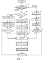
- Fig. 15 shows a flowchart of a working phase process of a routing controller according to an embodiment of the present invention.
- a request message when a request message is received, it is first determined that the request is a connection setup request or a connection release request at step 1501. If it is a connection setup request, the process proceeds to step 1502.
- step 1502 the resources between the designated entrance and exit nodes are checked, and if the check shows that there are no enough resources between the designated entrance and exit nodes to support the connection request, the process proceeds to step 1504.
- step 1504 a message is sent to the requestor to notify the requestor the failure of the request.
- step 1505 the failure number is then increased by 1, and the rejection rate of connections, i.e., the failure number/ (the failure number + the success number) is computed.
- step 1506 it is determined whether the rejection rate reaches a predetermined threshold of the rejection rate. If the predetermined threshold is reached, then the re-aggregation is triggered at step 1513 to perform the topology re-aggregation. After this, at step 1514, the counts of the success and failure of connections are reset to count again. Then at step 1515, LSA is generated based on the re-aggregated topology, and sent out. Thus a process for a request is over.
- step 1502 determines whether there are enough resources between the designated entrance and exit nodes to support the connection request. If at step 1502 the check shows that there are enough resources between the designated entrance and exit nodes to support the connection request, the process proceeds to step 1507.At step 1507, the request is sent to a next domain, and a connection setup indication is waited. After receiving the indication, at step 1508, the wavelength is allocated along the intra selected links to setup a connection. After this, at step 1509, the success number of connections is increased by 1. Then at step 1510, a re-flooding is triggered to send LSA information. Next at step 1511, the residual resources between the entrance and exit nodes are checked, and at step 1512, it is determined whether the amount of residual resources reaches a predetermined threshold of re-aggregation L a or not.
- step 1513 the process enters into step 1513 and performs the re-aggregation. After this, at step 1514 the counts of the success and failure connections are reset. The process then proceeds to step 1515 and the process for the request is terminated. If the threshold L a is not reached yet, then the process for the request is terminated directly.
- step 1501 if the request is a connection release request, the process proceeds to step 1503. At this step, the connection is released. The process goes to step 1510 subsequently, the steps as described above is performed until the process is terminated.
Landscapes
- Engineering & Computer Science (AREA)
- Computer Networks & Wireless Communication (AREA)
- Signal Processing (AREA)
- Artificial Intelligence (AREA)
- Evolutionary Computation (AREA)
- Medical Informatics (AREA)
- Data Exchanges In Wide-Area Networks (AREA)
Abstract
The present invention provides a method and an apparatus for topology aggregation and a routing controller. The method comprises: obtaining a link-diversity path number c(i,j,λ k ) between each pair of border nodes in a real topology GR; and obtaining a connectivity matrix C by utilizing said link-diversity path number c(i,j,λk ) and constructing a corresponding full-mesh topology GB. Moreover, the method further comprises compressing the resulting full-mesh topology into a bi-directional shuffle-net topology using the genetic algorithm. Therefore, according the present invention, more link information can be provided for routing decision and more accurate topology can be provided.
Description
- The present invention relates to the network technology, and more particularly, to a method and an apparatus for topology aggregation and a routing controller.
- Multiple routing domains are unexceptionally included in the IP network, the ATM (Asynchronous Transmission Mode) network or the emerging ASON (Automatic Switched Optical Network) .
- For the sake of scalability and security, internal topology information of each routing domain can be advertised to other routing domains in the network only after being aggregated by means of some topology aggregation method. Thus, each routing domain only maintains its own detailed topology information as well as aggregated topology information of other routing domains, thereby reducing the amount of information needing to be advertised and stored in the network.
- Generally, a topology aggregation process includes firstly constructing a full-mesh topology composed of border nodes based on a real topology, and further compressing, which is optional, the full-mesh topology into a sparser topology, such as a star topology, a tree topology and the like.
-
Fig. 1 shows an example of a topology aggregation process. As shown inFig. 1 ,topology 100 is a real topology comprising eight nodes 1-8, ten links, and two working wavelengths λ1 and λ2. InFig. 1 , the Nodes 1-4 are border nodes connected to external peer domains, the Nodes 5-8 are internal nodes, the solid line/the dashed line between nodes indicates the wavelength λ1/λ2 path of the link is free and a new connection can be established. - During the topology aggregation, internal nodes of
topology 100 are concealed, and only border nodes 1-4 and resource availability therebetween are reserved. The connectivity relation among these four border nodes can be represented by a connectivity matrix as shown in formula (1).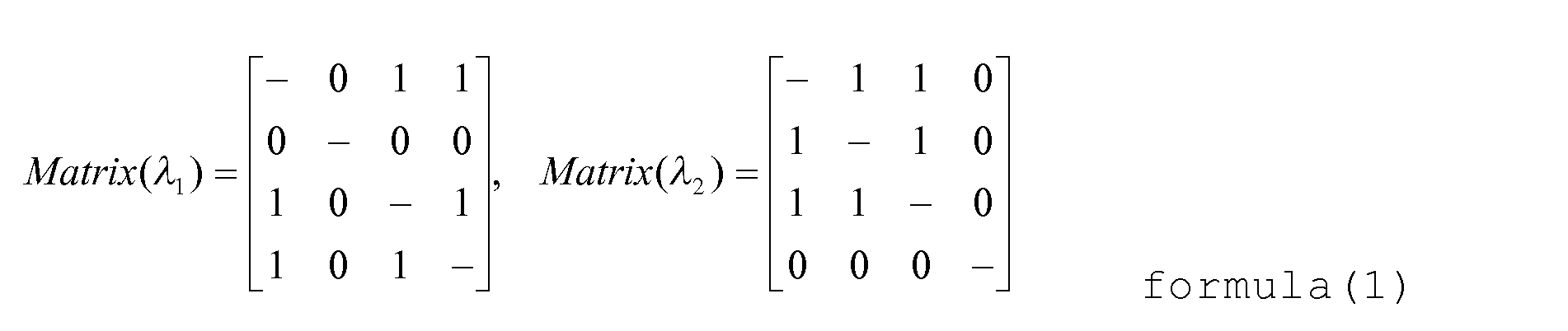
-
Topology 101 shown inFig. 1 has 4 border nodes 1-4, and thus the connectivity among border nodes can be represented by a 4×4 matrix for each wavelength λ1 and λ2. If there is a logical link enabling two border nodes to be connected (for example,node 1 andnode 4 can be connected with each other through wavelength λ1 path 1-5-6-3-4), the corresponding element of the matrix is set to 1, and 0 otherwise. -
Topology 101, which includes only border nodes 1-4, is a full-mesh topology constructed in accordance with the connectivity matrix. It can be seen that the number of links is reduced to 5 after the full-mesh topology construction (in the worst case, the number of links is 6, i.e., all nodes are connected). -
Topology 102 is the resultant topology after further compressing thetopology 101. The redundant logical links in theformer topology 101 are deleted, for example, the logical link of wavelength λ1 betweennode 3 andnode 4 is replaced with the path 3-1-4, and the logical link of wavelength λ2 betweennode 2 andnode 3 is replaced with the path 2-1-3. After compressing, the total number of links is further reduced to 3. - The existing topology aggregation technology is designed for the ATM network. There are three familiar methods, including the symmetric-node approach, the full-mesh approach and the star approach. The main idea of the symmetric-node approach is that all border nodes of the real topology are merged into a single virtual node and the connection property between border nodes is represented by a certain common value. The advantage of this approach is that only a very little amount of information needs to be exchanged. However, the disadvantage is that the provided information is too rough and inaccurate excessively, which will cause that the intra-domain resources can't be utilized appropriately. The full-mesh approach aims at the accuracy of the aggregation information. It assumes that all border nodes of the real topology are full connected by logical links, each of which is configured with one or more QoS parameters, such as delay or bandwidth. This approach reserves the connectivity property between border nodes of the original real topology accurately. However, because it must maintain the information of N (N - 1) /2 (N is the number of border nodes) logical links, when the network size is relatively large, the scalability is poor. The star approach assumes that there is a virtual node in the center, and all the border nodes in real topology are connected to it by logical links. Furthermore, each logical link may have different property. Thus, the star approach can represent more detailed link information, and may be much more accurate than the symmetric-node approach. At the same time, the star approach only needs to maintain the information of N logical links, and thus has better scalability than the full-mesh approach and is suitable for a relatively larger network.
- However, when the above-mentioned topology aggregation methods designed for the ATM network are applied to the optical network, these methods will be too rough and inaccurate to reach a good performance as a condition of wavelength continuity constraint needs to be met. Therefore, a more suitable solution for topology aggregation is required for the optical network such as ASON.
- To this end, it is an object of the present invention to provide a solution for topology aggregation more suitable for the optical network.
- According to an aspect of the present invention, there is provided a method for topology aggregation, comprising:
- obtaining the link-diversity path number c(i,j,λk ) between each pair of border nodes in a real topology GR; and
- obtaining a connectivity matrix C by utilizing said link-diversity path number c(i,j,λk ) and constructing a corresponding full-mesh topology GB.
- According to another aspect of the present invention, there is provided an apparatus for topology aggregation, comprising:
- link-diversity path number obtaining means configured to obtain the link-diversity path number c(i,j,λk ) between each pair of border nodes in a real topology GR;
- topology constructing means configured to obtain connectivity matrix C by using said link-diversity path number c(i,j,λk ) and construct a corresponding full-mesh topology GB.
- According to another aspect of the present invention, there is provided a routing controller, comprising:
- the apparatus for topology aggregation as described above; and
- link-state sending means configured to generate the Link-State Advertisement LSA information based on the topology obtained by the apparatus for topology aggregation, and send said LSA information out.
- More link information for routing decision and more accurate topology can be provided according the present invention.
- Other objects and effects of the present invention will be more apparent and easy to understand upon the comprehensive understanding of the present invention from the following detailed description, taken with reference to the drawings, wherein:
-
Fig. 1 shows an example of a topology aggregation process according to the prior art; -
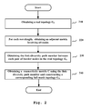
Fig. 2 shows a flow chart of a method for topology aggregation according to an embodiment of the present invention; -
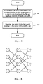
Fig. 3 shows a flow chart of a topology compression process according to an embodiment of the present invention; -
Fig. 4 shows an example of a bi-directional shuffle-net topology; -
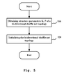
Fig. 5 shows a flow chart of a process of aggregating into a bi-directional shuffle-net topology according to an embodiment of the present invention; -
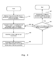
Fig. 6 shows a flow chart of a process of optimizing a bi-directional shuffle-net topology according to an embodiment of the present invention; -
Fig. 7 shows how to map nodes in a full-mesh topology to a bi-directional shuffle-net; -
Fig.8 shows an example of crossover and mutation operations according to an embodiment of the present invention; -
Fig. 9 shows a schematic block diagram of an apparatus for topology aggregation according to an embodiment of the present invention; -
Fig. 10 shows a schematic block diagram of an apparatus for topology aggregation according to another embodiment of the present invention; -
Fig. 11 shows a schematic block diagram of bi-directional shuffle-net topology optimizing means in an apparatus for topology aggregation according to another embodiment of the present invention; -
Fig. 12 shows a schematic block diagram of an apparatus for topology aggregation according to another embodiment of the present invention; -
Fig. 13 shows a schematic block diagram of a routing controller according to an embodiment of the present invention; -
Fig. 14 shows a starting phase flowchart of a routing controller according to an embodiment of the present invention; and -
Fig. 15 shows a working phase flowchart of a routing controller according to an embodiment of the present invention; - The like reference number indicates the same, similar, or corresponding features or functions throughout the drawings mentioned above.
- Hereinafter, the present invention will be described in detail by means of specific embodiments with reference to the drawings.
-
Fig. 2 shows a flow chart of a method for topology aggregation according to an embodiment of the present invention. In the following description of embodiments of the present invention, the topology aggregation is directed to one domain in AOSN. - As shown in
Fig. 2 , firstly, a real topology of the domain is obtained atstep 210.
- Wherein, V represents the set of nodes in the topology, i.e., V={v1,v2,...,vn}, and E represents the set of links among nodes, i.e., E={e1,e2,...,em}, and wherein each link can support one or more of wavelengths λ1,λ2,...,λw, n is the total number of nodes, and m is the total number of links, and W is the total number of wavelengths. It should be noted that GR can be a multi-graph wherein there are multiple optical fiber links between two nodes.
- Next, at
step 220, for each of wavelengths λ1, λ2, ..., λw, an adjacent matrix which involves all nodes is obtained:
wherein (i, j = 1, ... , n, k = 1, ... , W). For the wavelength λk, r(i,j,λ k )=the number of links if one or more links exist between node i and node j, and r(i,j,λ k )=0 otherwise. - Next at
step 230, the link-diversity path number c(i,j,λ k ) between each pair of border nodes is obtained from the adjacent matrix Rλk. The term "link-diversity path" used herein indicates a path without any shared links between two border nodes. - In an embodiment, computing the link-diversity path number between two border nodes is turned into computing maximum flow between two border nodes, as the link-diversity path number between two border nodes equals to the maximum flow between a source and a destination in the canal network. Thus, in this embodiment, the link-diversity path number between two border nodes is computed by calculating the maximum flow between them by utilizing a maximum flow algorithm.

- In an embodiment, the maximum flow between two border nodes is calculated by utilizing the existing highest-label-preflow-push algorithm. In an alternative embodiment, the maximum flow between two border nodes is calculated using the Augmenting Path Algorithm.
- Then, at
step 240, the connectivity matrix C is obtained by using the link-diversity path number c(i,j,λ k ) and a corresponding full-mesh topology GB is constructed. Wherein:

wherein, M = N(N-1)/2, VB = {v 1,v 2,...,vN } , EB = {e 1,e 2,...,eM } , e(i, j, λ k ) = c(i, j, λ k ) . - From the above embodiment, it can be seen that the connectivity matrix C of the present invention is different from the conventional one shown in formula (1). Instead of being represented by 0 and 1, the connectivity matrix of the present invention is represented by the link-diversity path number between two border nodes. By constructing the connectivity matrix C using the link-diversity path number, not only information on available wavelengths is provided, but also resources information on the wavelengths is provided. Thus, the more abundant information can be used for helping the selection of the optimal path, and the performance can be improved. For example, when a connection is setup, it is preferred to use the wavelength which has more resource and has less possibility to be exhausted.
- In another preferred embodiment, the resulting full-mesh topology is further compressed to obtain a sparser topology so that the amount of information to be exchanged among domains is further reduced.
-
Fig. 3 shows a flow chart of a topology compression process according to an embodiment of the present invention. As shown inFig. 3 , atstep 310, for the full-mesh topology, a bi-directional shuffle-net construction is performed to obtain a bi-directional shuffle-net topology in which all nodes are null. - A conventional shuffle-net (P, K) topology is a net which has N' = KPK nodes (P, K = 1, 2, ...) arranged in K columns and PK rows. Among others, each node in each column has P direct links to nodes in the next column, and the nodes in the last column also link to the nodes in first column so that a cylinder topology is formed. That is to say, the node (l, n) (l = 0, 1,..., PK-1, n = 0, 1,...,K-1) has P direct links to (l' , n'), (l' , n' +1), ..., (l' , n' + P -1) in the next column, where l' = 1 mod PK-1, n' = (n+1) mod K. The bi-directional shuffle-net topology is an extended version of the shuffle-net. The bi-directional shuffle-net topology is different from the conventional shuffle-net topology in that its links are all bi-directional, that is to say, each node in each column not only has P links to nodes in the next column, but has P links to nodes in the previous column.
-
Fig. 4 shows an example of a bi-directional shuffle-net topology, wherein K=2, P=2, N' = 8. As shown, the 8 nodes are arranged in 2 columns and 4 rows. Each node in each column has 2 links to the next and previous column respectively. With the bi-directional shuffle-net topology, logical links number can be reduced to PN' which is significantly reduced than that of the full-mesh topology which is the order of N2, thereby reducing the amount of the link information needing to be flooded and alleviating the load of the signaling network. - In the following, a process of the bi-directional shuffle-net topology construction of the present invention will be described in detail with reference to
Fig. 5 . - As shown in
Fig. 5 , first atstep 510, parameters K and P of the bi-directional shuffle-net topology are computed for the full-mesh topology, wherein K and P can be solved by the following formula:
wherein N is the number of nodes in the full-mesh topology, i.e., the number of border nodes in the real topology. - Next, at
step 520, the bi-directional shuffle-net topology is initialized by utilizing the parameters K and P obtained from formula ( 7 ), in order to obtain an initialized bi-directional shuffle-net topology:
wherein, V' is the set of nodes in the bi-directional shuffle-net topology, i.e., V'={v 1',v'2,...,v' N'}, and E' is the set of links in the bi-directional shuffle-net topology, i.e. , E'= {e' 1 ,e' 2,..., e'M' }, e' 1={λ'1,λ'2,...λ' W }, with N' =KPK, M' =KPK+1, V'⊇ VB, and E' ⊆ EB - Back to
Fig. 3 , atstep 320, the nodes in the full-mesh topology are mapped to nodes in the shuffle-net by means of a certain mapping relation, and corresponding logical link attributes are imparted to the bi-directional links in the shuffle-net. -
Fig. 6 shows a flow chart of a process of optimizing a bi-direction shuffle-net topology according to an embodiment of the present invention. In the embodiment, the Genetic Algorithm (GA) is used for optimizing the bi-direction shuffle-net topology. - As shown, at
step 610, the first generation P0 of the bi-direction shuffle-net topology is first obtained, which includes several chromosomes that can represent the way by which the nodes of the full-mesh topology are arranged in the bi-direction shuffle-net topology. In an embodiment, the one-dimensional literal permutation encoding is used to construct the chromosomes. For example, the chromosomes of the first generation P0 can be obtained by permuting N' nodes randomly:
- Taking a full-mesh topology of which the number of nodes is 7 as an example, a bi-directional shuffle-net topology with K=2, P=2 and N' = 8 is obtained by the aforesaid initializing operation. For a randomly generated chromosome '7 2 3 1 5 6 4 8', it represents the order according to which each node of the full-mesh topology is arranged in the bi-directional shuffle-net (wherein
node 8 is a virtual node that is filled for making up the deficiency), i.e.,node 7 in the full-mesh topology corresponds to the node (0, 0) in the bi-directional shuffle-net,node 2 corresponds to the node (1, 0),..,node 4 corresponds to the node (2, 1), andvirtual node 8 corresponds to the node (3, 1), as shown infig. 7 . - It can be seen that the chromosomes in the present invention are different from those ordinarily composed of 0-1 bit sequence. The present invention utilizes the one-dimensional literal permutation encoding, wherein each gene is the node number. Therefore, mutation operation on chromosomes of the present invention is position-based, which usually changes the position of genes in the chromosomes, thus it is ensured that the next generation can inherit most characteristics from their parents and compatible genes can be reserved.
- Next, at
step 620, after all nodes VB of the full-mesh topology GB is mapped into nodes V' of the bi-direction shuffle-net topology G' in accordance with each chromosome p, the mapping of logical links can be performed according to the node positions. As in the bi-directional shuffle-net topology mentioned above,node 7 is connected tonode node 7 are all deleted.Node 8 is a virtual node and doesn't participate in the mapping of logical links. For purpose of evaluating each chromosome, we can obtain a corresponding connectivity matrix C' of the bi-directional shuffle-net topology G':
- The connectivity matrix C' can be obtained in a manner similar to obtain the connectivity matrix C.
- At
step 630, a fitness value of each chromosome then is obtained with the connectivity matrix of border nodes of the real topology as a target function, which is:
wherein:
- In formula (11), the fitness value represents the degree of approximation between the connectivity matrix of the full-mesh topology and the connectivity matrix of the topology of the chromosome, the value of which is the opposite of the sum of the degree of deviation. The minus indicates that the smaller the deviation value is, the larger the fitness value is. The deviation value can be the absolute value of the ratio of the difference to the sum between the connectivity matrix of the topology of the chromosome and the target connectivity matrix. In an alternative embodiment, the deviation value is the absolute value of the difference between the connectivity matrix of the topology of the chromosome and the target connectivity matrix.
- Next, at
step 640, genetic operation is performed based on the obtained fitness value to obtain chromosomes of the next generation. In an embodiment, a selection operation is first performed on the chromosomes of the current generation based on the obtained fitness value to obtain the chromosomes for propagating the next generation. That is to say, the chromosome with a lower fitness value (for example, a fitness value lower than a threshold) is culled out, and only the chromosome with a higher fitness value is selected into the next generation. Cross-over and mutation operations are performed on the selected chromosomes to obtain the chromosomes of the next generation.Fig. 8 shows an example of crossover and mutation operations according to an embodiment of the present invention. It should be appreciated that the present invention is not limited to the crossover and mutation operations shown inFig. 8 . - Then, at
step 650, it is determined whether the number of the iteration reaches a predetermined threshold or not. If the answer is yes, the resulting chromosome with the best fitness is taken as the optimization result atstep 660, that is to say, the optimized bi-directional shuffle-net topology is obtained. If the answer is no, the process proceeds to step 620, and continues the iteration. - In another embodiment, the genetic operations are terminated if the fitness value of a chromosome reaches a predetermined threshold before the predetermined threshold for the number of the iteration is reached, and the bi-directional shuffle-net topology where the nodes are arranged and connected in accordance with the obtained chromosome, is taken as the resulting topology.
- The number of iteration can be determined based on need. The more the number of iteration is, the better the obtained result is, but more time is required to compute.
- The inventor has verified that the average deviation of each generation decreases quickly in the initial phase and reaches to a stable value after about 20 generations. After that, the average deviation fluctuates in a certain range. The average deviation after 30 generations is substantially smaller than 20 % , and the optimal individual deviation is substantially about 10%. It can be seen that the topology aggregation method of the present invention can achieve a more accurate topology and thus can provide more accurate and abundant information for routing decision, and thus can improve the performance.
- Furthermore, other suitable algorithms known to the skilled in the art, such as the heuristic algorithm and the like, can also be used to optimize the bi-directional shuffle-net topology.
- It can be seen from the description with reference to
Fig. 3 to 8 , that the topology aggregation method of the present invention provides detailed link information suitable for the optical network. More particularly, by employing the genetic algorithm to optimize the bi-directional shuffle-net topology, the more accurate topology structure is described using less logical links, and thus the performance is improved. - In another alternative embodiment, the nodes with more link-diversity path number in the full-mesh topology are mapped into nodes connected directly in a shuffle-net topology using the obtained connectivity matrix of the full-mesh topology, thereby compressing the full-mesh topology into a bi-directional shuffle-net topology using the heuristic approach.
- In still another alternative embodiment, the full-mesh topology is compressed into a symmetric-star topology by utilizing the obtained connectivity matrix of the full-mesh topology.
- When the network conditions change, for example the bandwidth availability of links changes, a re-aggregation operation needs be performed to update the advertised aggregation topology.
- In an embodiment of the present invention, the re-aggregation can be performed based on a predetermined time interval. In this embodiment, a re-aggregation time interval is predetermined, and the re-aggregation can be performed periodically based on the predetermined time interval, regardless of the bandwidth change conditions of links in the intra-domain.
- In another embodiment of the present invention, an event-based re-aggregation policy is adopted, that is to say, the re-aggregation is performed only when a predetermined event occurs. Preferably, a lazy re-aggregation policy can be used, i.e., the re-aggregation is performed only when a big topology change happens or the connection rejection rate reaches a predetermined threshold.
- In an embodiment, the re-aggregation is performed when a predetermined connection rejection rate is reached. As an example, during a predetermined re-aggregation time interval, the re-aggregation is performed immediately when the connection rejection rate r exceeds a predetermined threshold α, wherein α is a constant based on customer's QoS requirement, for example is 20%.
- In another example, the re-aggregation is performed when the topology changes greatly. In this embodiment, it is assumed that the link capacity is B channels, and the number of available channels at time t is ct. When the number of available channels ct at time t equals a value in a predetermined value sequence bk, the re-aggregation is performed.
- In a embodiment, the predetermined value sequence bk is constructed as follows: bk = {0,La},i.e., the re-aggregation is performed when the number of available channels ct become 0 or La.
- In another embodiment, the predetermined value sequence bk has more elements so that topology re-aggregation occurs at a lower frequency when there are more available channels and occurs at a higher frequency when there are less available channels. For example, the predetermined value sequence bk can be obtained by the following formula:

wherein K is the largest index such that bk < B for La>1 and bk = k for La=1. For example, in a case of 16 channels on each logical link, for La =2, the predetermined value sequence is bk = {0, 2, 4, 6, 10, 16} ; for La =3, bk = {0, 3, 6, 12, 16} ; and for La =4, bk = {0, 4, 8, 16} . The foregoing formula is just an example, and other methods can be used to obtain the predetermined value sequence bk. - In accordance with the re-aggregation policy of the present invention, the re-aggregation is preformed only when a big topology change occurs, and is not preformed when the topology change is small. Therefore, in the case of ensuring that aggregation topology is updated in time, the number of re-aggregation is reduced, thereby reducing the consumed resources due to the implementation of re-aggregation and improving the performance.
- It can be seen from the above description that, as the present invention constructs the connectivity matrix by utilizing "link-diversity path number", which provides not only the availability information on available wavelengths but also the resource abundance information on wavelengths, thereby more detailed link information is provided for the routing decision to optimize the source allocation and thus improve the network performance. In a preferred embodiment, the obtained full-mesh topology is further compressed, thereby reducing the amount of information to be exchanged among domains and further improving the performance. In a preferred embodiment, the full-mesh topology is compressed into a bi-directional shuffle-net topology to reduce the number of links significantly, thereby reducing the amount of routing information needing to be exchanged among domains and improving the performance. In another preferred embodiment, the re-aggregation is performed by utilizing an event-based lazy re-aggregation policy, thereby reducing the consumed resources due to the implementation of re-aggregation and improving the performance.
- Next, an apparatus for topology aggregation of the present invention will be further described hereinafter.
-
Fig. 9 shows anapparatus 900 for topology aggregation according to an embodiment of the present invention. As shown inFig. 9 , theapparatus 900 for topology aggregation includes: link-diversity path number obtaining means 910 configured to obtain the link-diversity path number c(i, j, λk ) between each pair of border nodes in a real topology; and topology constructing means 920 configured to obtain a connectivity matrix C by using the link-diversity path number c(i, j, λk ) and construct a corresponding full-mesh topology GB. - The link-diversity path number obtaining means 910 can operate in accordance with the above description with respect to steps 210-230 : an adjacent matrix is first computed from the real topology of a domain, and then the link-diversity path number between border nodes is obtained by calculating the maximum flow between border nodes. The highest-label-preflow-push algorithm, the Augmenting Path Algorithm, and other algorithms known to the skilled in the art can be used when computing the link-diversity path number.
- The topology constructing means 920 can operate in accordance with the above description with respect to step 240 : the connectivity matrix is constructed using the link-diversity path number obtained by the link-diversity path
number obtaining means 910. - From the above embodiment, it can be seen that the
apparatus 900 for topology aggregation of the present invention constructs the connectivity matrix using the link-diversity path number, which provides not only the information on available wavelengths but also the resource information on the abundance degree of wavelengths, thereby facilitating the route selection and improving the performance. - In a preferred embodiment, the
apparatus 900 for topology aggregation further includes topology compressing means 930 configured to compress the full-mesh topology, thereby further reducing the amount of information to be exchanged among domains. - As shown in
Fig. 10 , in an embodiment, the topology compressing means 930 includes: bi-directional shuffle-net topology constructing means 932 configured to initialize a bi-directional shuffle-net topology using determined structural parameters of the bi-directional shuffle-net topology; and bi-directional shuffle-net topology optimizing means 934 configured to optimize the bi-directional shuffle-net topology using the connectivity matrix of the full-mesh topology. - The bi-directional shuffle-net topology optimizing means 934 can further optimize the bi-directional shuffle-net topology based on the genetic algorithm.
Fig. 11 shows an embodiment of the bi-directional shuffle-net topology optimizing means 934 based on the genetic algorithm. The bi-directional shuffle-net topology optimizing means 934 includes: first generation generating means 9342 configured to obtain a first generation of the bi-direction shuffle-net topology randomly; connectivitymatrix obtaining means 9344 configured to obtain the connectivity matrix of chromosome of the current generation; fitness value computing means 9346 configured to compute the fitness value of each chromosome of the current generation using the connectivity matrix of border nodes of the real topology as a target function; genetic operation means 9348 configured to perform genetic operations on the chromosomes in the current generation based on the fitness value to obtain the chromosomes of the next generation, wherein the genetic operations includes a selection operation, a mutation operation, a cross-over operation, and the like.; and mapping means 9350 configured to, when a condition terminating the genetic operations is met, map the nodes of the full-mesh topology and the logical links into the bi-directional shuffle-net topology by utilizing the resulting optimized chromosome. Furthermore, other suitable algorithms known to the skilled in the art, such as the heuristic algorithm and the like, can also be used to optimize the bi-directional shuffle-net topology. - In an embodiment, the fitness value computed by the fitness value computing means 9346 is the absolute of the difference between the connectivity matrix of chromosome of said current generation and that of border nodes of the real topology. While in another embodiment, the fitness value is the absolute value of the ratio of the difference to the sum between the connectivity matrix of chromosome of said current generation and that of border nodes of the real topology.
- In an embodiment, the condition terminating the genetic operations is that the number of iteration exceeds a predetermined value or the fitness value reaches a predetermined value.
- In an embodiment, the chromosome is based on one-dimensional literal permutation encoding.
- From the above embodiment, it can be seen that the number of the logical links is reduced significantly and the more accurate topology structure is provided by further optimizing the bi-directional shuffle-net topology utilizing the genetic algorithm, thereby improving the performance.
- In a preferred embodiment, as shown in
Fig. 12 , theapparatus 900 for topology aggregation further includes a re-aggregation triggering means 940 configured to trigger a re-aggregation of topology when the network status changes or trigger a re-aggregation of topology based on a predetermined time interval. In an embodiment, based on a lazy re-aggregation policy, the re-aggregation triggering means 940 triggers the re-aggregation when a predetermined topology change event occurs or the connection rejection rate reaches a predetermined threshold. The predetermined topology change event can be an event that the amount of available resources increases or decreases to a predetermined value, and the re-aggregation occurs at a lower frequency when there are more available resources and occurs at a higher frequency when there are less available resources. - Besides, the present invention also provides a routing controller.
Fig. 13 shows a schematic block diagram of a routing controller according to an embodiment of the present invention. As shown inFig. 13 , therouting controller 1300 incudes : realtopology obtaining means 1310 for obtain a real topology of one domain, theapparatus 900 for topology aggregation of the present invention for aggregating the real topology of one domain, and link-state sending means 1320 for generating the Link-State Advertisement (LSA) information based on the topology obtained by theapparatus 900 for topology aggregation, and for sending the LSA information out. Theapparatus 900 for topology aggregation in the routing controller constructs the connectivity matrix using the link-diversity path number, which provides not only information on available wavelengths, but also resource information on wavelengths, thereby facilitating route selection and improving the performance. -
Fig. 14 shows a flowchart of a starting phase process of a routing controller according to an embodiment of the present invention. As shown inFig. 14 , after the routing controller starting to operate, the real topology obtaining means first obtains a real topology of one domain atstep 1410. Atstep 1420, the apparatus for topology aggregation then aggregates the real topology. Next atstep 1430, the link-state sending means generates LSA information based on the aggregated topology and sends it out. - In the working phase, the apparatus for topology aggregation will trigger a re-aggregation when a re-aggregation condition is met. The re-aggregation can be triggered when the network status changes or triggered based on a predetermined time interval. In an embodiment, based on a lazy re-aggregation policy, the re-aggregation is triggered when a predetermined topology change event occurs or the connection rejection rate reaches a predetermined threshold. Besides, the predetermined topology change event can be an event that the amount of available resources increases or decreases to a predetermined value, and the predetermined event occurs at a lower frequency when there are more available resources and occurs at a higher frequency when there are less available resources.
-
Fig. 15 shows a flowchart of a working phase process of a routing controller according to an embodiment of the present invention. - As shown in
Fig. 15 , at the working phase, when a request message is received, it is first determined that the request is a connection setup request or a connection release request atstep 1501. If it is a connection setup request, the process proceeds to step 1502. - At
step 1502, the resources between the designated entrance and exit nodes are checked, and if the check shows that there are no enough resources between the designated entrance and exit nodes to support the connection request, the process proceeds to step 1504. Atstep 1504, a message is sent to the requestor to notify the requestor the failure of the request. Atstep 1505, the failure number is then increased by 1, and the rejection rate of connections, i.e., the failure number/ (the failure number + the success number) is computed. - Next, at
step 1506, it is determined whether the rejection rate reaches a predetermined threshold of the rejection rate. If the predetermined threshold is reached, then the re-aggregation is triggered atstep 1513 to perform the topology re-aggregation. After this, atstep 1514, the counts of the success and failure of connections are reset to count again. Then atstep 1515, LSA is generated based on the re-aggregated topology, and sent out. Thus a process for a request is over. - On the other hand, if at
step 1502 the check shows that there are enough resources between the designated entrance and exit nodes to support the connection request, the process proceeds to step1507.At step 1507, the request is sent to a next domain, and a connection setup indication is waited. After receiving the indication, atstep 1508, the wavelength is allocated along the intra selected links to setup a connection. After this, atstep 1509, the success number of connections is increased by 1. Then atstep 1510, a re-flooding is triggered to send LSA information. Next atstep 1511, the residual resources between the entrance and exit nodes are checked, and atstep 1512, it is determined whether the amount of residual resources reaches a predetermined threshold of re-aggregation La or not. If the threshold La is reached, the process enters intostep 1513 and performs the re-aggregation. After this, atstep 1514 the counts of the success and failure connections are reset. The process then proceeds to step 1515 and the process for the request is terminated. If the threshold La is not reached yet, then the process for the request is terminated directly. - In
step 1501, if the request is a connection release request, the process proceeds to step 1503. At this step, the connection is released. The process goes to step 1510 subsequently, the steps as described above is performed until the process is terminated. - It will be noted that more specific technical details known to the skilled to the art, which may be necessary to the implementation of the present invention, are omitted in above description for much better understanding of the present invention.
- The specification is provided for the purpose of illustration and description, but is not exhaustive or limited the invention to the disclosed form. Various modifications and alterations are apparent to the skilled in the art.
- Therefore, the embodiments were chosen and described in order to best explain the principles of the invention, the practical application thereof, and to enable the skilled in the art to understand that all modifications and alterations made without departing from the spirit of the present invention fall into the protection scope of the present invention as defined in the appended claims.
Claims (25)
- A method for topology aggregation, comprising:obtaining a link-diversity path number c(i,j,λ k ) between each pair of border nodes in a real topology GR; andobtaining a connectivity matrix C by utilizing said link-diversity path number c(i,j,λk ) and constructing a corresponding full-mesh topology GB.
- The method of claim 1, wherein said link-diversity path number is obtained by calculating a maximum flow between border nodes.
- The method of claim 2, wherein calculating the maximum flow between border nodes is performed by utilizing the highest-label-preflow-push algorithm.
- The method of claim 1, further comprising:performing topology compression on said full-mesh topology.
- The method of claim 4, wherein said performing topology compression comprises:determining structural parameters of a bi-directional shuffle-net topology;initializing said bi-directional shuffle-net topology by utilizing said structural parameters;optimizing said bi-directional shuffle-net topology by utilizing said connectivity matrix.
- The method of claim 5, wherein optimizing said bi-directional shuffle-net topology is based on the genetic algorithm, and comprises:obtaining a first generation of said bi-directional shuffle-net topology randomly;obtaining a connectivity matrix of a topology of a chromosome of the current generation;computing a fitness value for each chromosome of the current generation using the connectivity matrix of border nodes the real topology as a target function;performing genetic operations on each chromosome of the current generation based on said fitness value to obtain the chromosomes of the next generation;repeating the operations of obtaining the connectivity matrix of the topology of the chromosome, computing the fitness value, and performing the genetic operations until a condition terminating the genetic operations is met; andmapping the nodes of the full-mesh topology into the bi-directional shuffle-net topology by utilizing the resulting chromosome to obtain a optimized bi-directional shuffle-net topology.
- The method of claim 6, wherein said fitness value is the opposite of the sum of each deviation value, said each deviation value being the absolute value of the ratio of the difference to the sum between the connectivity matrix of the topology of the chromosome and the connectivity matrix of said full-mesh topology.
- The method of claim 6, wherein the condition terminating the genetic operations is that the number of iteration reaches a predetermined value.
- The method of claim 6, wherein said chromosome utilizes one-dimensional literal permutation encoding.
- The method of claim 1, further comprising:performing a re-aggregation of topology when the network status changes.
- The method of claim 10, wherein the re-aggregation of topology is based on a lazy re-aggregation policy and is performed when a predetermined topology change event occurs or the connection rejection rate reaches a predetermined threshold.
- The method of claim 11, wherein said predetermined topology change event is an event that the amount of available resources becomes a predetermined value, and said predetermined topology change event occurs at a lower frequency when there are more available resources and occurs at a higher frequency when there are less available resources.
- An apparatus for topology aggregation, comprising:link-diversity path number obtaining means configured to obtain a link-diversity path number c(i,j,λ k ) between each pair of border nodes in a real topology GR;topology constructing means configured to obtain a connectivity matrix C by using said link-diversity path number c(i,j,λk ) and construct a corresponding full-mesh topology GB.
- The apparatus of claim 13, wherein said link-diversity path number obtaining means is further configured to obtain said link-diversity path number by computing a maximum flow between border nodes.
- The apparatus of claim 14, wherein computing the maximum flow between border nodes is performed by utilizing the highest-label-preflow-push algorithm.
- The apparatus of claim 13, further comprising:topology compressing means configured to compress said full-mesh topology.
- The apparatus of claim 16, wherein said topology compressing means comprises:bi-directional shuffle-net topology constructing means configured to initialize a bi-directional shuffle-net topology by utilizing determined structural parameters of the bi-directional shuffle-net topology; andbi-directional shuffle-net topology optimizing means configured to optimize said bi-directional shuffle-net topology by utilizing the connectivity matrix of border nodes of the real topology as a target.
- The apparatus of claim 17, wherein said bi-directional shuffle-net topology optimizing means is based on the genetic algorithm, and comprises:first generation generating means configured to obtain a first generation of said bi-directional shuffle-net topology randomly;connectivity matrix obtaining means configured to obtain a connectivity matrix of a topology of a chromosome of the current generation;fitness value computing means configured to compute a fitness value for each chromosome of the current generation using said connectivity matrix of border nodes of the real topology as a target;genetic operation means configured to perform genetic operations on each chromosome of the current generation based on said fitness value to obtain the chromosomes of the next generation; andmapping means configured to, when a condition terminating the genetic operations is met, map the nodes of the full-mesh topology into the bi-directional shuffle-net topology by utilizing the resulting chromosomes.
- The apparatus of claim 18, wherein said fitness value is the opposite of the sum of each deviation value, said deviation value being the absolute value of the ratio of the difference to the sum between the connectivity matrix of the topology of the chromosome of said current generation and the connectivity matrix of said full-mesh topology.
- The apparatus of claim 18, wherein the condition terminating the genetic operations is that the number of iteration reaches a predetermined value.
- The apparatus of claim 18, wherein said chromosome is based on one-dimensional literal permutation encoding.
- The apparatus of claim 13, further comprising:re-aggregation triggering means configured to trigger the re-aggregation of topology when the network status changes.
- The apparatus of claim 22, wherein said re-aggregation triggering means is based on a lazy re-aggregation policy and triggers the re-aggregation of topology when a predetermined topology change event occurs or the connection rejection rate reaches a predetermined threshold.
- The apparatus of claim 23, wherein said predetermined topology change event is an event that the amount of available resources increases or decreases to a predetermined value, and said predetermined topology change event occurs at a lower frequency when there are more available resources and occurs at a higher frequency when there are less available resources.
- A routing controller, comprising:an apparatus for topology aggregation of anyone of claims 13 to 24; andlink-state sending means, configured to generate the Link-State Advertisement LSA information based on the topology obtained by the apparatus for topology aggregation, and send said LSA information out.
Applications Claiming Priority (1)
| Application Number | Priority Date | Filing Date | Title |
|---|---|---|---|
| PCT/CN2008/000741 WO2009124419A1 (en) | 2008-04-10 | 2008-04-10 | Topology abstraction method, topology abstraction apparatus and route controller |
Publications (1)
| Publication Number | Publication Date |
|---|---|
| EP2271028A1 true EP2271028A1 (en) | 2011-01-05 |
Family
ID=41161512
Family Applications (1)
| Application Number | Title | Priority Date | Filing Date |
|---|---|---|---|
| EP08733944A Withdrawn EP2271028A1 (en) | 2008-04-10 | 2008-04-10 | Topology abstraction method, topology abstraction apparatus and route controller |
Country Status (5)
| Country | Link |
|---|---|
| US (1) | US8406154B2 (en) |
| EP (1) | EP2271028A1 (en) |
| JP (1) | JP2011517220A (en) |
| KR (1) | KR20100133003A (en) |
| WO (1) | WO2009124419A1 (en) |
Families Citing this family (8)
| Publication number | Priority date | Publication date | Assignee | Title |
|---|---|---|---|---|
| US10108616B2 (en) * | 2009-07-17 | 2018-10-23 | International Business Machines Corporation | Probabilistic link strength reduction |
| US9467348B2 (en) * | 2014-01-31 | 2016-10-11 | Viasat, Inc. | Systems, methods, and devices for reducing overhead messaging in networks |
| JP6492977B2 (en) * | 2015-06-01 | 2019-04-03 | 富士通株式会社 | Parallel computing device, parallel computing system, node allocation program, and node allocation method |
| US10038623B2 (en) * | 2016-10-24 | 2018-07-31 | Microsoft Technology Licensing, Llc | Reducing flooding of link state changes in networks |
| US11184245B2 (en) | 2020-03-06 | 2021-11-23 | International Business Machines Corporation | Configuring computing nodes in a three-dimensional mesh topology |
| CN113572690B (en) * | 2021-06-11 | 2023-02-24 | 深圳市国电科技通信有限公司 | Data transmission method for reliability-oriented electricity consumption information acquisition service |
| CN114448863B (en) * | 2022-01-06 | 2022-11-22 | 武汉烽火技术服务有限公司 | Computing method and device for searching cross-domain path |
| CN119697037B (en) * | 2024-11-26 | 2026-04-21 | 天翼云科技有限公司 | Auxiliary decision-making method and auxiliary decision-making system for cloud virtual network node deployment |
Family Cites Families (11)
| Publication number | Priority date | Publication date | Assignee | Title |
|---|---|---|---|---|
| JPH1098477A (en) * | 1996-09-25 | 1998-04-14 | Toshiba Corp | Route selection method and communication system |
| US7046634B2 (en) * | 2002-04-15 | 2006-05-16 | Tropic Networks Inc. | Method and apparatus for selecting maximally disjoint shortest paths in a network |
| US7813270B2 (en) * | 2003-05-15 | 2010-10-12 | Alcatel-Lucent Usa Inc. | Route precomputation method and apparatus for bandwidth guaranteed traffic |
| US7463579B2 (en) * | 2003-07-11 | 2008-12-09 | Nortel Networks Limited | Routed split multilink trunking |
| CN100428736C (en) * | 2005-02-02 | 2008-10-22 | 华为技术有限公司 | A Topological Method for Realizing Hierarchical Routing by One-time Routing Computation |
| US7639688B2 (en) * | 2005-07-18 | 2009-12-29 | Cisco Technology, Inc. | Automatic protection of an SP infrastructure against exterior traffic |
| GB2440287A (en) * | 2005-09-27 | 2008-01-23 | Roke Manor Research | Disjoint pair formation in a network using shortest path determination |
| CN100369432C (en) * | 2005-11-25 | 2008-02-13 | 北京邮电大学 | A Spanning Tree Topology Abstraction Method Applied to Asymmetric Networks |
| JP4494357B2 (en) * | 2006-03-08 | 2010-06-30 | 富士通株式会社 | Path route calculation method and optical communication network to which this method is applied |
| US20070300239A1 (en) * | 2006-06-23 | 2007-12-27 | International Business Machines Corporation | Dynamic application instance placement in data center environments |
| US20100061231A1 (en) * | 2006-11-06 | 2010-03-11 | Janos Harmatos | Multi-domain network and method for multi-domain network |
-
2008
- 2008-04-10 EP EP08733944A patent/EP2271028A1/en not_active Withdrawn
- 2008-04-10 US US12/735,732 patent/US8406154B2/en not_active Expired - Fee Related
- 2008-04-10 KR KR1020107025146A patent/KR20100133003A/en not_active Withdrawn
- 2008-04-10 WO PCT/CN2008/000741 patent/WO2009124419A1/en not_active Ceased
- 2008-04-10 JP JP2011503322A patent/JP2011517220A/en active Pending
Non-Patent Citations (1)
| Title |
|---|
| See references of WO2009124419A1 * |
Also Published As
| Publication number | Publication date |
|---|---|
| US8406154B2 (en) | 2013-03-26 |
| JP2011517220A (en) | 2011-05-26 |
| US20110080851A1 (en) | 2011-04-07 |
| KR20100133003A (en) | 2010-12-20 |
| WO2009124419A1 (en) | 2009-10-15 |
Similar Documents
| Publication | Publication Date | Title |
|---|---|---|
| US8406154B2 (en) | Method and apparatus for topology aggregation and routing controller | |
| US11082262B2 (en) | Flow entry generating method and apparatus | |
| US5687168A (en) | Link state routing device in ATM communication system | |
| US8059528B2 (en) | Method of estimating restoration capacity in a network | |
| EP1769599B1 (en) | Wavelength selection | |
| US20110090791A1 (en) | Distributed Constraints-Based Inter-Domain Network Traffic Management | |
| EP2159974A1 (en) | Method and equipment for establishing a connection | |
| Roy et al. | An efficient multi-objective QoS-routing algorithm for wireless multicasting | |
| CN113098713B (en) | End-to-end reliability assessment method for spatial information network | |
| CN109347657B (en) | Method for constructing virtual data domain of scientific and technological service under SDN mode | |
| CN101557300B (en) | Method, device and equipment for network topology reconstruction | |
| CN110166381A (en) | It is a kind of to distribute the computer installation of power telecom network resource, device and method | |
| CN110414094A (en) | A kind of business different degree configuration method between power communication network node | |
| CN120980153A (en) | A multi-protocol fusion emergency communication dispatch method | |
| US8532496B2 (en) | Path establishment | |
| US11387926B2 (en) | Efficient transfer of sensor data on dynamic software defined network (SDN) controlled optical network | |
| CN103179035A (en) | Optical transmission network and method and device for selecting fixed routes thereof | |
| CN117134895A (en) | A QKP-based QKD network routing addressing method, storage device and intelligent terminal | |
| Ghosh et al. | A probabilistic scheme for hierarchical qos routing | |
| Mohammad et al. | Localized quality based QoS routing | |
| KR100369935B1 (en) | A method of aggregating a metric information in a hierarchical network | |
| He et al. | Node-merging method in passive network topology detection | |
| KR20010076617A (en) | Topology aggregation method of the PNNI hierachy using a parameter grouping scheme | |
| Bai et al. | Virtual network reconfiguration in optical cloud substrates | |
| Oikonomou et al. | Techniques for probabilistic multi-layer network analysis |
Legal Events
| Date | Code | Title | Description |
|---|---|---|---|
| PUAI | Public reference made under article 153(3) epc to a published international application that has entered the european phase |
Free format text: ORIGINAL CODE: 0009012 |
|
| 17P | Request for examination filed |
Effective date: 20101110 |
|
| AK | Designated contracting states |
Kind code of ref document: A1 Designated state(s): AT BE BG CH CY CZ DE DK EE ES FI FR GB GR HR HU IE IS IT LI LT LU LV MC MT NL NO PL PT RO SE SI SK TR |
|
| AX | Request for extension of the european patent |
Extension state: AL BA MK RS |
|
| DAX | Request for extension of the european patent (deleted) | ||
| STAA | Information on the status of an ep patent application or granted ep patent |
Free format text: STATUS: THE APPLICATION HAS BEEN WITHDRAWN |
|
| 18W | Application withdrawn |
Effective date: 20121105 |