EP2271004A2 - Wireless communication frame structure and apparatus - Google Patents
Wireless communication frame structure and apparatus Download PDFInfo
- Publication number
- EP2271004A2 EP2271004A2 EP10168482A EP10168482A EP2271004A2 EP 2271004 A2 EP2271004 A2 EP 2271004A2 EP 10168482 A EP10168482 A EP 10168482A EP 10168482 A EP10168482 A EP 10168482A EP 2271004 A2 EP2271004 A2 EP 2271004A2
- Authority
- EP
- European Patent Office
- Prior art keywords
- frame
- ieee
- legacy
- mini
- sub
- Prior art date
- Legal status (The legal status is an assumption and is not a legal conclusion. Google has not performed a legal analysis and makes no representation as to the accuracy of the status listed.)
- Withdrawn
Links
- 238000000034 method Methods 0.000 claims abstract description 46
- 238000004590 computer program Methods 0.000 claims 1
- 230000005540 biological transmission Effects 0.000 description 79
- 238000010586 diagram Methods 0.000 description 52
- 230000011664 signaling Effects 0.000 description 15
- 230000008569 process Effects 0.000 description 12
- 239000000969 carrier Substances 0.000 description 7
- 238000001514 detection method Methods 0.000 description 7
- 230000008859 change Effects 0.000 description 6
- 239000012141 concentrate Substances 0.000 description 4
- 235000008694 Humulus lupulus Nutrition 0.000 description 3
- 230000006872 improvement Effects 0.000 description 3
- 238000000638 solvent extraction Methods 0.000 description 3
- 238000001228 spectrum Methods 0.000 description 3
- 239000000203 mixture Substances 0.000 description 2
- 238000005192 partition Methods 0.000 description 2
- 238000013468 resource allocation Methods 0.000 description 2
- 230000001360 synchronised effect Effects 0.000 description 2
- 230000007704 transition Effects 0.000 description 2
- 230000003044 adaptive effect Effects 0.000 description 1
- 238000013507 mapping Methods 0.000 description 1
Images












Classifications
-
- H—ELECTRICITY
- H04—ELECTRIC COMMUNICATION TECHNIQUE
- H04B—TRANSMISSION
- H04B7/00—Radio transmission systems, i.e. using radiation field
- H04B7/24—Radio transmission systems, i.e. using radiation field for communication between two or more posts
- H04B7/26—Radio transmission systems, i.e. using radiation field for communication between two or more posts at least one of which is mobile
- H04B7/2643—Radio transmission systems, i.e. using radiation field for communication between two or more posts at least one of which is mobile using time-division multiple access [TDMA]
- H04B7/2656—Radio transmission systems, i.e. using radiation field for communication between two or more posts at least one of which is mobile using time-division multiple access [TDMA] for structure of frame, burst
-
- H—ELECTRICITY
- H04—ELECTRIC COMMUNICATION TECHNIQUE
- H04L—TRANSMISSION OF DIGITAL INFORMATION, e.g. TELEGRAPHIC COMMUNICATION
- H04L27/00—Modulated-carrier systems
- H04L27/26—Systems using multi-frequency codes
- H04L27/2601—Multicarrier modulation systems
- H04L27/2602—Signal structure
-
- H—ELECTRICITY
- H04—ELECTRIC COMMUNICATION TECHNIQUE
- H04L—TRANSMISSION OF DIGITAL INFORMATION, e.g. TELEGRAPHIC COMMUNICATION
- H04L27/00—Modulated-carrier systems
- H04L27/26—Systems using multi-frequency codes
- H04L27/2601—Multicarrier modulation systems
- H04L27/2602—Signal structure
- H04L27/2603—Signal structure ensuring backward compatibility with legacy system
-
- H—ELECTRICITY
- H04—ELECTRIC COMMUNICATION TECHNIQUE
- H04L—TRANSMISSION OF DIGITAL INFORMATION, e.g. TELEGRAPHIC COMMUNICATION
- H04L27/00—Modulated-carrier systems
- H04L27/26—Systems using multi-frequency codes
- H04L27/2601—Multicarrier modulation systems
- H04L27/2602—Signal structure
- H04L27/2605—Symbol extensions, e.g. Zero Tail, Unique Word [UW]
- H04L27/2607—Cyclic extensions
-
- H—ELECTRICITY
- H04—ELECTRIC COMMUNICATION TECHNIQUE
- H04L—TRANSMISSION OF DIGITAL INFORMATION, e.g. TELEGRAPHIC COMMUNICATION
- H04L5/00—Arrangements affording multiple use of the transmission path
- H04L5/0001—Arrangements for dividing the transmission path
- H04L5/0003—Two-dimensional division
- H04L5/0005—Time-frequency
- H04L5/0007—Time-frequency the frequencies being orthogonal, e.g. OFDM(A) or DMT
-
- H—ELECTRICITY
- H04—ELECTRIC COMMUNICATION TECHNIQUE
- H04L—TRANSMISSION OF DIGITAL INFORMATION, e.g. TELEGRAPHIC COMMUNICATION
- H04L5/00—Arrangements affording multiple use of the transmission path
- H04L5/003—Arrangements for allocating sub-channels of the transmission path
- H04L5/0048—Allocation of pilot signals, i.e. of signals known to the receiver
-
- H—ELECTRICITY
- H04—ELECTRIC COMMUNICATION TECHNIQUE
- H04L—TRANSMISSION OF DIGITAL INFORMATION, e.g. TELEGRAPHIC COMMUNICATION
- H04L5/00—Arrangements affording multiple use of the transmission path
- H04L5/003—Arrangements for allocating sub-channels of the transmission path
- H04L5/0053—Allocation of signalling, i.e. of overhead other than pilot signals
-
- H—ELECTRICITY
- H04—ELECTRIC COMMUNICATION TECHNIQUE
- H04L—TRANSMISSION OF DIGITAL INFORMATION, e.g. TELEGRAPHIC COMMUNICATION
- H04L5/00—Arrangements affording multiple use of the transmission path
- H04L5/003—Arrangements for allocating sub-channels of the transmission path
- H04L5/0053—Allocation of signalling, i.e. of overhead other than pilot signals
- H04L5/0055—Physical resource allocation for ACK/NACK
-
- H—ELECTRICITY
- H04—ELECTRIC COMMUNICATION TECHNIQUE
- H04L—TRANSMISSION OF DIGITAL INFORMATION, e.g. TELEGRAPHIC COMMUNICATION
- H04L5/00—Arrangements affording multiple use of the transmission path
- H04L5/14—Two-way operation using the same type of signal, i.e. duplex
-
- H—ELECTRICITY
- H04—ELECTRIC COMMUNICATION TECHNIQUE
- H04W—WIRELESS COMMUNICATION NETWORKS
- H04W72/00—Local resource management
- H04W72/04—Wireless resource allocation
- H04W72/044—Wireless resource allocation based on the type of the allocated resource
-
- H—ELECTRICITY
- H04—ELECTRIC COMMUNICATION TECHNIQUE
- H04L—TRANSMISSION OF DIGITAL INFORMATION, e.g. TELEGRAPHIC COMMUNICATION
- H04L27/00—Modulated-carrier systems
- H04L27/26—Systems using multi-frequency codes
- H04L27/2601—Multicarrier modulation systems
- H04L27/2647—Arrangements specific to the receiver only
- H04L27/2655—Synchronisation arrangements
-
- H—ELECTRICITY
- H04—ELECTRIC COMMUNICATION TECHNIQUE
- H04W—WIRELESS COMMUNICATION NETWORKS
- H04W28/00—Network traffic management; Network resource management
- H04W28/02—Traffic management, e.g. flow control or congestion control
- H04W28/04—Error control
-
- H—ELECTRICITY
- H04—ELECTRIC COMMUNICATION TECHNIQUE
- H04W—WIRELESS COMMUNICATION NETWORKS
- H04W72/00—Local resource management
- H04W72/04—Wireless resource allocation
- H04W72/044—Wireless resource allocation based on the type of the allocated resource
- H04W72/0446—Resources in time domain, e.g. slots or frames
-
- H—ELECTRICITY
- H04—ELECTRIC COMMUNICATION TECHNIQUE
- H04W—WIRELESS COMMUNICATION NETWORKS
- H04W72/00—Local resource management
- H04W72/04—Wireless resource allocation
- H04W72/044—Wireless resource allocation based on the type of the allocated resource
- H04W72/0453—Resources in frequency domain, e.g. a carrier in FDMA
-
- H—ELECTRICITY
- H04—ELECTRIC COMMUNICATION TECHNIQUE
- H04W—WIRELESS COMMUNICATION NETWORKS
- H04W72/00—Local resource management
- H04W72/12—Wireless traffic scheduling
- H04W72/1215—Wireless traffic scheduling for collaboration of different radio technologies
-
- H—ELECTRICITY
- H04—ELECTRIC COMMUNICATION TECHNIQUE
- H04W—WIRELESS COMMUNICATION NETWORKS
- H04W84/00—Network topologies
- H04W84/02—Hierarchically pre-organised networks, e.g. paging networks, cellular networks, WLAN [Wireless Local Area Network] or WLL [Wireless Local Loop]
- H04W84/04—Large scale networks; Deep hierarchical networks
- H04W84/042—Public Land Mobile systems, e.g. cellular systems
- H04W84/047—Public Land Mobile systems, e.g. cellular systems using dedicated repeater stations
-
- H—ELECTRICITY
- H04—ELECTRIC COMMUNICATION TECHNIQUE
- H04W—WIRELESS COMMUNICATION NETWORKS
- H04W88/00—Devices specially adapted for wireless communication networks, e.g. terminals, base stations or access point devices
- H04W88/08—Access point devices
- H04W88/10—Access point devices adapted for operation in multiple networks, e.g. multi-mode access points
Definitions
- the global time-frequency resource zones may be configured within the DL sub-frame and/or UL sub-frame so that different Mobile Stations (MSs) may not use the same global zone for DL and UL transmissions, which can lead to interference issues.
- MSs Mobile Stations
- either odd-hop or even-hop access nodes may use the zone for transmission to (or reception from) an MS.
- Two global time/frequency resource zones one configured for odd-hop RS-to-MS communication and one configured for even-hop RS-to-MS communications may be configured for the DL sub-frame.
- two global zones may be configured for the uplink sub-frame.
- a node simultaneously receives from (or transmits to) its parent node and child node using the same time-frequency resource. Data can be recovered using interference avoidance or interference removal.
- Global time-frequency resource zones are defined for signaling exchange between multiple nodes (BS, and/or RS, and/or MS) for self-configuration and self-organization operation.
- the concepts of the present invention may be used in various communication systems, in some embodiments these concepts can be particularly applicable to the IEEE 802.16 standard, which is commonly referred to as the WiMAX standard, and in particular the next generation of the IEEE 802.16 standard commonly known as the IEEE 802.16m standard.
- IEEE 802.16m control and data zones 222 are functions to support IEEE 802.16m-enabled MSs when an IEEE 802.16m data burst is scheduled.
- the extended basic resource unit (also called basic channel unit) within the extended mini-slot is defined by concatenation of B basic resource units, one from each mini-slot within the extended mini-slot; where B is the number of mini-slots within an extended mini-slot.
- the purpose of the extended basic channel unit is to allow scalability of resource size based on the number of mini-slots in the extended mini-slot and to allow the same control channel structure for mini-slots and extended mini-slots.
- IEEE 802.16m TDD ratios are defined as M:N where M is the number of IEEE 802.16m DL mini-slots in a frame and N is the number of IEEE 802.16m UL mini-slots in a frame.
- the TDD ratio is 2:3.
- Figure 6 is a block diagram of a representative example of a superframe structure.
- Figure 6 shows the case of time division duplexing (TDD) of downlink and uplink transmissions.
- TDD time division duplexing
- FDD frequency division duplexing
- the downlink and uplink sub-frames shown in Figure 6 are on separate carrier frequencies rather than separate time.
- the following description of DL sub-frames and UL sub-frames still apply to the DL and UL of an FDD system, respectively.
- the IEEE 802.16m-enabled MS may decode the primary broadcast channel within the IEEE 802.16m zone.
- the primary broadcast channel can be transmitted at the beginning or at a predefined resource location within the IEEE 802.16m preamble mini-slot.
- a superframe can consist of L frames, where L is predefined and the superframe boundary can be indicated in the legacy MAP in case there is no IEEE 802.16m common-sync channel. Otherwise, the superframe boundary is implied by the location of the common-sync channel detected in step 902).
- the primary broadcast channel can contain deployment-wide PHY parameters which do not change from one superframe to another. For example, system bandwidth, multi-carrier configuration, system time, etc.
- the primary broadcast channel can be encoded or employ repetition coding over multiple superframes to improve robustness.
- the IEEE 802.16m-enabled MS can decode the system parameter broadcast messages.
- the system parameter broadcast messages can be sent on a regular traffic channel, and contain physical layer and MAC layer MAC system parameters that are semi-statically configured, e.g. HO parameters, power control parameters, etc.
- the IEEE 802.16m-enabled MS can also decode the legacy system broadcast messages (i.e. DCD and UCD) within the legacy DL zone to obtain common system information shared between the legacy system and IEEE 802.16m system.
- the primary and secondary broadcast channel can be superposed onto the same OFDMA time/frequency resource and successive decoding can be employed to decode the primary and secondary broadcast channels.
- the sub-carrier reserved for legacy systems can be dynamically changed from frame to frame.
- a transmission frame consists of time division multiplexing (TDM) and/or frequency division multiplexing (FDM) of two or more systems or waveforms onto the same RF carrier and bandwidth.
- TDM time division multiplexing
- FDM frequency division multiplexing
- Frame structure 1250 is comprised of DL mini-slots 1201 and UL mini-slots 1203.
- Required guard bands 1257 separate the frames.
- Optional guard bands 1259 are only required if the occurrence of legacy and IEEE 802.16m mini-slots are not synchronized across sectors.
- FIG 12A is a block diagram showing a second example multi-band scenario (Scenario 1) where the available IEEE 802.16m system bandwidth of 20 MHz 1300 is partitioned into multiple segments 1302, 1304 and 1306.
- scenario 1 the available IEEE 802.16m system bandwidth of 20 MHz 1300 is partitioned into multiple segments 1302, 1304 and 1306.
- the IEEE 802.16m sub-channel is defined (i.e. mapped to physical sub-carriers) within each segment.
- the IEEE 802.16m control channels are defined within each segment to indicate the sub-channel resource allocation across that segment.
- the IEEE 802.16m-enabled MS decodes the primary broadcast channel and the secondary broadcast control channels on the IEEE 802.16m preamble mini-slot.
- the information in these channels includes system bandwidth, bandwidth segments, reserved tones, and guard tones.
- FIG 14C shows further details of the multi-band scenario 1500 illustrated in Figure 14A showing a second option of where the preamble mini-slot could be located.
- Multi-band scenario 1580 is comprised of DL mini-slots 1591 and UL mini-slots 1593.
- a system bandwidth can be divided into multiple segments with each segment having the same or different bandwidths.
- Each segment can support one or multiple systems or OFDMA transmission formats.
- a system, transmission format or time-frequency resource definition can span one or more segments.
- RS 1902 communicates with its parent node BS 1904 (or parent RS) using frequency F2 on DL and frequency F1 on UL.
- RS 2002 can simultaneously receive on the UL on F1 from MS/child RS 2008 and receive on the DL on F1 from BS/parent RS 2004 on the global zone.
- the same frame structure same as that defined for multi-hop relay can be used to support network coding.
- Global zones as described above can be defined for a network node to simultaneously multicast the transmission to both parent node(s) and child node(s), as well as receive simultaneous transmissions from parent node(s) and child node(s).
Landscapes
- Engineering & Computer Science (AREA)
- Signal Processing (AREA)
- Computer Networks & Wireless Communication (AREA)
- Mobile Radio Communication Systems (AREA)
- Bidirectional Digital Transmission (AREA)
- Time-Division Multiplex Systems (AREA)
- Radio Relay Systems (AREA)
Abstract
Description
- The present invention relates to wireless communication systems.
- The Worldwide Interoperability for Microwave Access Forum (WiMAX) has developed a specification that describes a radio interface for wireless data communications. This specification is known as the Institute of Electrical and Electronic Engineers (IEEE) 802.16e-2005 standard (referred to herein as the "IEEE 802.16e standard") and is incorporated herein by reference. WiMAX is intended to provide higher capacity, allow greater communications distances and provide mobility (access across different access points).
- The Institute of Electrical and Electronics Engineers, Inc. (IEEE) 802.16 Broadband Wireless Access Working Group Task Group m (TGm) is chartered to develop an amendment to IEEE Standard 802.16, to be known as IEEE 802.16m: P802.16 - IEEE Standard for Local and Metropolitan Area Networks - Part 16: Air Interface for Fixed Broadband Wireless Access Systems - Amendment: IEEE Standard for Local and Metropolitan Area Networks - Part 16: Air Interface for Fixed and Mobile Broadband Wireless Access Systems - Advanced Air Interface. The documents related to the IEEE 802.16m standard are available at nttp://www.ieee802.org/16/tgm/. These can be considered at any date by utilizing the services of the Internet Web Archive, available at nttp://www.arcnive.org/. For example, the following URL provides access to a copy of the IEEE 802.16m documents as they appeared on December 10th 2007, the filing date of the application: http://web.archive.org/web/20071210/ieee802.org/16/tgm/, of which this application is a Continuation in Part.
- All documents, whether listed as contributed or official, listed in http://web.archive.org/web/20071210/ieee802.org/16/tgm/ are incorporated herein by reference in their entirety.
- Of particular relevance to the background of this application are those documents contributed to the above noted IEEE 802.16m working group by the inventors named herein.
- In some embodiments, the concepts of the present invention may be used in conjunction with the IEEE 802.16 standard, which is commonly referred to as the WiMAX standard, and in particular the next generation of the IEEE 802.16 standard commonly known as the IEEE 802.16m standard.
- Some embodiments described herein employ time division duplexing (TDD), and some embodiments employ frequency division duplexing (FDD).
- According to a first aspect, there is provided multiple types of systems or OFDMA transmission formats that can be multiplexed in time division fashion or frequency division fashion or both. Each frequency division segment can further be time division multiplexed across multiple systems. The same superframe format, frame format and smaller frame format can be applied to time division multiplexing, frequency division multiplexing and a mixture of both. The same synchronization channels and system parameters of the broadcast channel can be applied to time division multiplexing, frequency division multiplexing and a mixture of both. This aspect can be applied to a single hop system consisting of a base station and a mobile station, and multi-hop systems consisting of a base station, relay stations (or intermediate nodes) and mobile stations. This aspect can be applied to the transmission and multiplexing of multiple systems across each hop of a multi-hop network.
- According to a second aspect there is provided a transmission frame consisting of time division multiplexing (TDM) and/or frequency division multiplexing (FDM) of two or more systems or waveforms onto the same Radio Frequency (RF) carrier and bandwidth. A transmission frame consists of multiple equal-size smaller frames, where each smaller frame constitutes the basic unit of time-frequency resource definition, time-division duplex (TDD) partitioning between downlink and uplink, and time division multiplexing (TDM) between two or more OFDMA systems or formats. The start of the TDD downlink portion or uplink portion within a frame can be different for different systems that are multiplexed onto the same RF carrier and bandwidth. A superframe consists of multiple equal-size frames, where each frame is further divided into multiple equal-size smaller frames. The superframe boundary and duration can be different for different systems that are multiplexed onto the same RF carrier and bandwidth in TDM or FDM fashion. A transmission frame or superframe consists of a universal synchronization channel such as a universal preamble shared by multiple types of systems and system-specific synchronization channels or system-specific preambles used by the corresponding system. The system-specific synchronization channel occurs at a fixed location within the superframe of the corresponding system. The universal synchronization channel and system-specific synchronization channel puncture out one or more symbols of one or more designated smaller frames within a frame or superframe. A superframe consists of one or more system parameter broadcast channels at predefined locations within the superframe. The system parameter broadcast channels are superposed onto the same time-frequency resource within the superframe. The Hybrid ARQ (HARQ) acknowledgement (ACK) and retransmission timing of a system within a frame or superframe are defined by the ACK delay, retransmission delay, the number of parallel HARQ channels, the TDD Downlink (DL) to Uplink (UL) ratio and the TDM resource allocated to the system. This information is signaled by the base station in broadcast or unicast fashion to the mobile station and the mobile station deduces the HARQ ACK timing and retransmission timing based on this information.
- According to a third aspect, there is provided a superframe consisting of multiple equal-size frames, where each frame can be further divided into multiple equal-size smaller frames. A preamble frame or smaller frame is located in a predefined location within the superframe and defines the superframe boundary. A preamble frame or smaller frame consists of a common-synchronization channel and the cell-specific synchronization channel. The common-synchronization channel is scrambled by unique sequences to indicate the types of systems multiplexed onto the same RF carrier and bandwidth as that of the preamble frame or smaller frame.
- According to a fourth aspect, there is provided a system bandwidth divided into multiple segments with the same or different bandwidth. Each segment supports one or multiple systems or OFDMA transmission formats. A system, transmission format or time-frequency resource definition can span one or more segments. A base station can simultaneously support different types of systems or OFDMA transmission formats on different segments. The base station can transmit/receive in single carrier fashion, that is one center frequency and one Fast Fourier Transform (FFT) across multiple segments or in multi-carrier fashion, that is multiple center frequencies and FFTs across multiple segments. A mobile station can transmit/receive in single carrier fashion, that is one center frequency and one FFT across multiple segments or in multi-carrier fashion, that is multiple center frequencies and FFTs across multiple segments. A mobile station can transmit/receive on one or multiple segments using different center frequencies and FFT sizes from those of the base station. A mobile station performs synchronization and network entry on one or more specific segments implicitly indicated by the base station through the presence of preamble in that segment or explicitly indicated by the base station through system parameter broadcast signaling. A mobile station can be semi-statically or dynamically allocated to one or multiple segments after network entry. Guard bands or tones between segments can be semi-statically or dynamically included or excluded. One or more segments contain the universal synchronization channels and system parameter broadcast channels shared by multiple systems. Additional system-specific synchronization channels and system parameter broadcast channels can be located in the same or different sets of segments. The universal synchronization channels and system parameter broadcast channels can be located on the center frequency of the entire band, with predefined bandwidths.
- According to a fifth aspect, there is provided a node which transmits signals to its parent node and child node at the same time on the same RF carrier. A node receives signals from its parent node and child node at the same time on the same RF carrier. A node transmits a signal to its parent node and child node at the same time on the same RF carrier on global time-frequency resource zones. A node receives signals from its parent node and child node at the same time on the same RF carrier on global time-frequency resource zones. A set of orthogonal time-frequency sub-channels is defined in a global time-frequency resource zone. The set of sub-channels is shared by the transmission to parent node and child node or reception from parent node and child node. The global time-frequency resource zones may be configured within the DL sub-frame and/or UL sub-frame so that different Mobile Stations (MSs) may not use the same global zone for DL and UL transmissions, which can lead to interference issues. On a global time-frequency zone, either odd-hop or even-hop access nodes may use the zone for transmission to (or reception from) an MS. Two global time/frequency resource zones, one configured for odd-hop RS-to-MS communication and one configured for even-hop RS-to-MS communications may be configured for the DL sub-frame. Similarly, two global zones may be configured for the uplink sub-frame. A node simultaneously receives from (or transmits to) its parent node and child node using the same time-frequency resource. Data can be recovered using interference avoidance or interference removal. Global time-frequency resource zones are defined for signaling exchange between multiple nodes (BS, and/or RS, and/or MS) for self-configuration and self-organization operation.
- Embodiments may include a modified frame structure to a wireless standard, which can be an OFDMA standard, e.g. a modified frame structure to the IEEE 802.16 standard thereby enabling backwards compatibility (also known as legacy support) for legacy systems (e.g. a deployed system such as that based on the IEEE 802.16e standard). In some embodiments, this modified frame structure may be used in conjunction with the IEEE 802.16m standard.
- According to a sixth aspect, there is provided a method comprising providing a frame, the frame including a downlink sub-frame and an uplink sub-frame, portions of the downlink sub-frame and uplink sub-frame being allocated for communication with a mobile station configured to operate utilizing a legacy wireless standard such as a legacy OFDMA standard, e.g. a legacy IEEE 802.16 standard, and portions of the downlink sub-frame and uplink sub-frame being allocated for communication with a mobile station configured to operate utilizing a modified version of that standard, e.g. the IEEE 802.16m standard; and using the frame to wirelessly communicate with a mobile station in at least one of the uplink and downlink directions.
- According to a seventh aspect, there is provided a method of operating a wireless communications network having multiple mobile stations and a serving base station, the multiple mobile stations including a first mobile station and a second mobile station, the method comprising dividing system bandwidth into a plurality of bandwidth segments, one for each mobile station; and the bandwidth segment associated with the first mobile station being configured to operate utilizing a wireless standard such as an OFDM standard e.g. the IEEE 802.16m standard.
- The invention will now be described in greater detail with reference to the accompanying diagrams, in which:
-
Figure 1 is a block diagram of a representative frame structure used in connection with some embodiments; -
Figure 2 is a block diagram of a representative sub-frame structure used in connection with some embodiments; -
Figure 3A is a block diagram showing a representative frame structure where a legacy system and an IEEE 802.16m system share a common UL to DL switch time but have a different DL to UL switch time; -
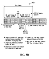
Figure 3B is a block diagram showing a representative frame structure where a legacy system and an IEEE 802.16m system share a common DL to UL switch time but have a different UL to DL switch time; -
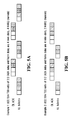
Figure 4A is a block diagram illustrating DL Hybrid Automatic Repeat Request (HARQ) round trip delay, with an IEEE 802.16m TDD ratio of 2:3; -
Figure 4B is a block diagram illustrating DL HARQ round trip delay, with an IEEE 802.16m TDD ratio of 3:2; -
Figure 5A is a block diagram illustrating UL HARQ round trip delay, with an IEEE 802.16m TDD ratio of 2:3; -
Figure 5B is a block diagram illustrating UL HARQ round trip delay, with an IEEE 802.16m TDD ratio of 3:2; -
Figure 6 is a block diagram of a representative superframe structure used in connection with some embodiments; -
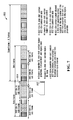
Figure 7 is a block diagram of a representative alternative superframe structure used in connection with some embodiments; -
Figure 8A is a flowchart of exemplary steps for initial system access for an IEEE 802.16m Mobile Station (MS) according to one embodiment; -
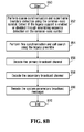
Figure 8B is a flowchart of exemplary steps for initial system access for an IEEE 802.16m Mobile Station (MS) according to another embodiment; -
Figure 9 is a block diagram of a representative frame structure where a superframe consists of K frames according to one embodiment; -
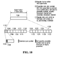
Figure 10 is a block diagram of a representative frame structure where a superframe consists of P mini-slots according to one embodiment; -
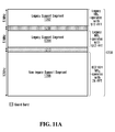
Figure 11A is a block diagram of a first example multi-band scenario where the available IEEE 802.16m system bandwidth of 20MHz 1200 is partitioned into multiple segments; -
Figure 11B is a block diagram showing a representative frame structure of the multi-band scenario illustrated inFigure 11A ; -
Figure 11C is a flowchart showing the steps for initial access for an IEEE 802.16m-enabled MS using the multi-band scenario ofFigures 11A and11B ; -
Figure 12A is a block diagram showing a second example multi-band scenario where the available IEEE 802.16m system bandwidth is partitioned into multiple segments; -
Figure 12B is a block diagram showing a representative frame structure of the multi-band scenario illustrated inFigure 12A ; -
Figure 12C is a flowchart showing the steps for initial access for an IEEE 802.16m-enabled MS using the multi-band scenario ofFigures 12A and12B ; -
Figure 13A is a block diagram showing a third example multi-band scenario where the available IEEE 802.16m system bandwidth is partitioned into multiple segments; -
Figure 13B is a block diagram showing a representative frame structure of the multi-band scenario illustrated inFigure 13A showing a first option of where the preamble mini-slot could be located; -
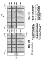
Figure 13C is a block diagram showing a representative frame structure of the multi-band scenario illustrated inFigure 13A showing a second option of where the preamble mini-slot could be located; -
Figure 13D is a flowchart showing the steps for initial access for an IEEE 802.16m-enabled MS using the multi-band scenario ofFigure 13B ; -
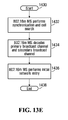
Figure 13E is a flowchart showing the steps for initial access for an IEEE 802.16m-enabled MS using the multi-band scenario ofFigure 13C ; -
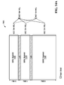
Figure 14A is a block diagram showing a fourth example multi-band scenario where the available IEEE 802.16m system bandwidth is partitioned into multiple segments; -
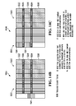
Figure 14B is a block diagram showing a representative frame structure of the multi-band scenario illustrated inFigure 14A showing a first option of where the preamble mini-slot could be located; -
Figure 14C is a block diagram showing a representative frame structure of the multi-band scenario illustrated inFigure 14A showing a second option of where the preamble mini-slot could be located; -
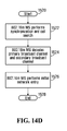
Figure 14D is a flowchart showing steps for initial access for an IEEE 802.16m-enabled MS using the multi-band scenario ofFigure 14B ; -
Figure 14E is a flowchart showing the steps for initial access for an IEEE 802.16m-enabled MS using the multi-band scenario ofFigure 14C . -
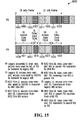
Figure 15 is a block diagram showing a first example of a frame structure to accomplish multi-hop relay, for TDD, provided in accordance with one embodiment; -
Figure 16A is a block diagram of a representative wireless communication network illustrating a second embodiment in TDD supporting multi-hop relay; -
Figure 16B is a block diagram illustrating DL and UL sub-frames for the second example shown inFigure 16A ; -
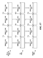
Figure 17 is a block diagram showing further details of the second embodiment for multi-hop relay; -
Figure 18 is a block diagram showing further details of a third embodiment for multi-hop relay, but for FDD; -
Figure 19 is a block diagram showing further details of a fourth embodiment for multi-hop relay, also for FDD; and -
Figure 20 is a block diagram showing further details of a fifth embodiment for multi-hop relay, also for FDD. - Although the concepts of the present invention may be used in various communication systems, in some embodiments these concepts can be particularly applicable to the IEEE 802.16 standard, which is commonly referred to as the WiMAX standard, and in particular the next generation of the IEEE 802.16 standard commonly known as the IEEE 802.16m standard.
-
Figure 1 shows a frame structure which provides legacy support, provided in accordance with one embodiment. The frame structure is segmented to provide a first set of zones specifically for legacy support, and a second set of zones designed for communication only with terminals operating under a new standard such as the IEEE 802.16m standard. The frame structure illustrated inFigure 1 is intended only as a representative example of one frame structure which could be used to provide legacy support to terminals operating under the IEEE 802.16e standard. Persons skilled in the art will appreciate that alternative frame structures could be employed to serve the same purpose. - Embodiments of the present invention support both Time Division Duplexing (TDD) and Frequency Division Duplexing (FDD) modes.
Figure 1 shows a representative frame structure for the case of TDD downlink and uplink transmission. For the case of FDD of downlink and uplink transmission, the downlink (DL)sub-frame 202 and uplink (UL)sub-frame 204 are on separate carrier frequencies rather than at separate time. The following description ofDL sub-frame 202 andUL sub-frame 204 also apply to an FDD system. - Operationally, the frame structure of
Figure 1 supports both IEEE 802.16m and legacy systems by defining a legacy zone and an IEEE 802.16m zone whereby legacy zones are located at the beginning of the legacy DL sub-frame and the legacy UL sub-frame. The duration of the legacy zone and the IEEE 802.16m zone can be semi-statically or dynamically configured. - In
Figure 1 , aDL sub-frame 202 is shown, contiguous with aUL sub-frame 204. The length of each sub-frame is designed to be compatible with legacy systems.DL sub-frame 202 is separated fromUL sub-frame 204 by a Transmit Transition Gap (TTG) 206, which is a buffer period between transmission and reception of frames which prevents downlink and uplink collisions.UL sub-frame 204 terminates with a Receive Transition Gap (RTG) 208 which performs a similar function asTTG 206. -
DL sub-frame 202 is comprised ofdownlink preamble 210, frame control header (FCH) 212, which provides frame configuration information,MAP message 214, legacy (i.e. 802.16e)data zone 216, and IEEE 802.16m control anddata zones 217. -
UL sub-frame 204 is comprised of 802.16eUL ranging zone 218, 802.16e UL control anddata zones 220, and IEEE 802.16m UL control anddata zones 222. -
Preamble 210,FCH 212,TTG 206,RTG 208 and 802.16eUL ranging zone 218 are mandatory functions to support legacy MSs. -
MAP message 214, 802.16e data zones 216, and 802.16e UL control anddata zones 220 are functions to support legacy 802.16e MSs when 802.16e data bursts are scheduled. - IEEE 802.16m control and
data zones 222 are functions to support IEEE 802.16m-enabled MSs when an IEEE 802.16m data burst is scheduled. - Different TDD ratios can be configured for a legacy system and an IEEE 802.16m system. The DL/UL switch of legacy systems is broadcast in the Downlink Channel Descriptor/Uplink Channel Descriptor (DCD/UCD) and is synchronized across the network. In some embodiments, it should be almost statically configured. For IEEE 802.16m, the DL/UL switch should also be statically configured. IEEE 802.16m and legacy systems can have different TDD DL/UL switch times.
-
Legacy system preamble 210 can be used by legacy terminals and IEEE 802.16m terminals for synchronization and system access. An additional IEEE 802.16m preamble (not shown), such as the common-synchronization channel, can be added to enhance the synchronization performance of IEEE 802.16m terminals. -
Figure 2 is a block diagram of arepresentative sub-frame structure 300 used in connection with some embodiments.Figure 2 shows the case of time division duplexing (TDD) of downlink and uplink transmissions. For the case of FDD of downlink and uplink transmissions, the downlink and uplink sub-frames shown inFigure 2 are on separate carrier frequencies rather than separate time. The following description applies equally well to the DL and UL of an FDD system respectively. - In some embodiments, a
legacy frame 300 of 5 ms duration is comprised of eightmini-slots Mini-slots DL sub-frame 301, whilesub-frames UL sub-frame 303. Each mini-slot contains six symbols, though this number can vary. - In some embodiments, the first mini-slot (in this case mini-slot 306) is the preamble mini-slot. For the case of TDD, one symbol is punctured for use as TDD guard time, that is, TTG/RTG. The remaining 5 symbols consist of preamble, FCH and MAP and possibly legacy data zones.
- In some embodiments, the DL mini-slots start with the preamble mini-slots, and the UL mini-slots start with the legacy UL mini-slot.
- The IEEE 802.16m
mini-slots - In some embodiments, an extended mini-slot can be defined by concatenating multiple adjacent or non-adjacent mini-slots. In the DL, the channelization is defined across the mini-slots within the extended mini-slot to improve time diversity for control and data. In the UL, the time is defined within a mini-slot. However, an MS can be assigned resources across the mini-slots within the extended mini-slot, to improve UL coverage.
- In both DL and UL, the extended basic resource unit (also called basic channel unit) within the extended mini-slot is defined by concatenation of B basic resource units, one from each mini-slot within the extended mini-slot; where B is the number of mini-slots within an extended mini-slot. The purpose of the extended basic channel unit is to allow scalability of resource size based on the number of mini-slots in the extended mini-slot and to allow the same control channel structure for mini-slots and extended mini-slots.
- The extended mini-slots and normal mini-slots can coexist in the system in frequency division multiplexing (FDM) and/or time division multiplexing (TDM) fashion. Separate sets of OFDMA time/frequency resources are allocated to mini-slots and extended mini-slots. The channelization for control and data is defined within each set of OFDMA time/frequency resources.
- IEEE 802.16m TDD ratios are defined as M:N where M is the number of IEEE 802.16m DL mini-slots in a frame and N is the number of IEEE 802.16m UL mini-slots in a frame. In the example of
Figure 2 , the TDD ratio is 2:3. -
Figure 3A is a block diagram showing aframe 400 where a legacy system and an IEEE 802.16m system share a common UL to DL switch time, but have a different DL to UL switch time. This case has some value where a legacy system profile doesn't support UL with more than a certain number of symbols, e.g. 21. -
Figure 3B is a block diagram showing arepresentative frame structure 450 where a legacy system and an IEEE 802.16m system share a common DL to UL switch time but have a different UL to DL switch time. This case has some value where a high DL:UL ratio is desired and where there is a desire to ensure the legacy system has lower latency in UL feedback/requests. - Note that in some embodiments, the gap between an UL and DL sub-frame is always adjacent to a legacy mini-slot so that legacy users only need to search the first mini-slot for information.
-
Figure 4A is a block diagram illustrating DL HARQ round trip delay, with an IEEE 802.16m TDD ratio of 2:3. The minimum HARQ ACK and Retrx (retransmission) delay and the number of HARQ channels are defined in system broadcast signaling which corresponds to particular partitioning of legacy, IEEE 802.16m, and TDD ratios (for the case of TDD). With these parameters defined, the precise HARQ timing can be deduced. In the embodiment ofFigure 4A , ACK delay and retrx delay are four mini-slots, with two HARQ channels. -
Figure 4B is a block diagram illustrating DL HARQ round trip delay, with an IEEE 802.16m TDD ratio of 3:2. In the embodiment ofFigure 4B , ACK delay and retrx delay are four mini-slots, with four HARQ channels. -
Figure 5A is a block diagram illustrating UL HARQ round trip delay, with an IEEE 802.16m TDD ratio of 2:3. In the embodiment ofFigure 5A , ACK delay and retrx delay are four mini slots, with four HARQ channels. -
Figure 5B shows UL HARQ round trip delay, with an IEEE 802.16m TDD ratio of 3:2. In the embodiment ofFigure 5B , ACK delay and retrx delay are four mini slots, with four HARQ channels. - In the embodiments such as those illustrated in each of
Figures 4A, 4B ,5A and 5B , the first mini-slot is reserved for legacy systems. - In
Figures 4A and5B , each shaded block illustrates the corresponding DL tx/retrx and UL ACK. Similarly, inFigures 5A and 5B each shed block illustrates the corresponding UL tx/retrax and DL ACK. -
Figure 6 is a block diagram of a representative example of a superframe structure.Figure 6 shows the case of time division duplexing (TDD) of downlink and uplink transmissions. For the case of frequency division duplexing (FDD) of downlink and uplink transmissions, the downlink and uplink sub-frames shown inFigure 6 are on separate carrier frequencies rather than separate time. The following description of DL sub-frames and UL sub-frames still apply to the DL and UL of an FDD system, respectively. - In some embodiments,
superframe 700 is comprised of K frames. In some embodiments, K = 4.Superframe 700 is comprised of a plurality offrames - The
first mini-slot 712 at the start of thesuperframe 700 or some predetermined fixed location within the superframe contains the IEEE 802.16m system parameter broadcast channels such as the primary and secondary broadcast channels and may also contain additional preamble (such as the common-sync channel) for IEEE 802.16m-only. In addition, the additional preamble for IEEE 802.16m-only (such as a common-sync channel) can be located at a fixed location within a superframe but separately from the primary/secondary broadcast channels. - In this embodiment, each frame (such as frame 702) is comprised of a
DL sub-frame 706 and aUL sub-frame 708. Each sub-frame (such as DL sub-frame 706) is comprised of a number of mini-slots which, in this embodiment, is four. - In this embodiment, each sub-frame is separated from each other by a gap, such as a TTG/
RTG 710. -
DL sub-frame 706 is comprised of DL mini-slots 712, 714, 716 and 718.DL mini-slot 712 is reserved for a legacy DL preamble, FCH, MAP and legacy data.DL mini-slot 714 is a legacy DL mini-slot containing legacy DL data.DL mini-slot 716 is an IEEE 802.16m preamble mini-slot containing IEEE 802.16m primary and secondary broadcast channels.DL mini-slot 716 may also contain IEEE 802.16m preamble data such as a common-sync channel.DL mini-slot 718 is an IEEE 802.16m DL mini-slot containing IEEE 802.16m control and data. - In this embodiment,
UL sub-frame 708 is comprised of UL mini-slots 722, 720, 724, and 726. UL mini-slot 720 is a legacy UL mini-slot containing legacy UL data and control.UL mini-slots -
Gap 710 separatesframe 702 fromframe 704.Frame 704 is comprised ofDL sub-frame 740 andUL sub-frame 742.DL sub-frame 740 is comprised of DL mini-slots 730, 732, 734, and 736. DL mini-slot 730 is reserved for legacy DL preamble, FCH, MAP and legacy data.DL mini-slot 732 is a legacy DL mini-slot containing legacy DL data.DL mini-slots -
DL sub-frame 740 is separated fromUL sub-frame 742 bygap 710.UL sub-frame 708 is comprised of UL mini-slots 750, 752, 754 and 756. UL mini-slot 750 is a legacy UL mini-slot containing legacy UL data and control.UL mini-slots -
Figure 7 is a block diagram of an embodiment of an alternative superframe structure as compared to the one illustrated inFigure 6 . The difference in this embodiment is that a common-sync channel/symbol 802 is located prior to the superframe 800 boundary. The common-sync channel/symbol can be contained within the IEEE 802.16mpreamble mini-slot 804. -
Figure 8A is a flowchart of exemplary steps for initial system access for an MS configured to support IEEE 802.16m according to one embodiment. - At
step 900, the procedure is started. - At
step 902, the IEEE 802.16m-enabled MS may perform coarse synchronization and superframe boundary detection using the IEEE 802.16m common-sync channel/symbol (if such channel/symbol exists). - At
step 904, the IEEE 802.16m-enabled MS may perform fine synchronization and a cell search using the legacy preamble. - At
step 906, the IEEE 802.16m-enabled MS may decode the legacy broadcast control channels, for example, FCH and MAP and therefore determine the location of the IEEE 802.16m zone from the legacy MAP. - At
step 908, the IEEE 802.16m-enabled MS may decode the primary broadcast channel within the IEEE 802.16m zone. The primary broadcast channel can be transmitted at the beginning or at a predefined resource location within the IEEE 802.16m preamble mini-slot. (A superframe can consist of L frames, where L is predefined and the superframe boundary can be indicated in the legacy MAP in case there is no IEEE 802.16m common-sync channel. Otherwise, the superframe boundary is implied by the location of the common-sync channel detected in step 902). The primary broadcast channel can contain deployment-wide PHY parameters which do not change from one superframe to another. For example, system bandwidth, multi-carrier configuration, system time, etc. The primary broadcast channel can be encoded or employ repetition coding over multiple superframes to improve robustness. - At
step 910, the IEEE 802.16m-enabled MS may decode the secondary broadcast channel within the IEEE 802.16m zone. The secondary broadcast channel can be transmitted at the beginning of a predefined resource location within the IEEE 802.16m preamble mini-slot. The secondary broadcast channel can be encoded in one superframe. The secondary broadcast channel can contain essential PHY parameters for the proper decoding of PHY frame and PHY traffic and control channel within the corresponding superframe. The information (channelization, zones configuration) can change every superframe. - At
step 912, the IEEE 802.16m-enabled MS can decode the system parameter broadcast messages. The system parameter broadcast messages can be sent on a regular traffic channel, and contain physical layer and MAC layer MAC system parameters that are semi-statically configured, e.g. HO parameters, power control parameters, etc. - Note that the IEEE 802.16m-enabled MS can also decode the legacy system broadcast messages (i.e. DCD and UCD) within the legacy DL zone to obtain common system information shared between the legacy system and IEEE 802.16m system. The primary and secondary broadcast channel can be superposed onto the same OFDMA time/frequency resource and successive decoding can be employed to decode the primary and secondary broadcast channels.
- At
step 914, the procedure terminates. -
Figure 8B is a flowchart of exemplary steps for initial system access for an IEEE 802.16m Mobile Station (MS) according to another embodiment. - At
step 950, the procedure is started. - At
step 952, the IEEE 802.16m-enabled MS performs coarse synchronization and superframe boundary detection using the common-sync symbol. The MS then detects if the legacy support is enabled or disabled through scrambling sequence detection on the common-sync symbol. - At
step 954, the IEEE 802.16m-enabled MS performs fine synchronization and cell search using the legacy preamble. - At
step 956, the IEEE 802.16m-enabled MS decodes the primary broadcast channel. The primary broadcast channel is transmitted at a predefined resource location within the preamble mini-slot. The primary broadcast channel contains deployment-wide PHY parameters which don't change from one superframe to another. For example, system bandwidth, multi-carrier configuration, system time, etc. The primary broadcast channel can be encoded or employ repetition coding over multiple superframes to improve robustness. - At
step 958, the IEEE 802.16m-enabled MS decodes the secondary broadcast channel. The secondary broadcast channel is transmitted at a predefined resource location within the preamble mini-slot. The secondary broadcast channel is encoded in one superframe. It contains essential PHY parameters for the proper decoding of the PHY frame and PHY traffic and control channel within the corresponding superframe. The information (channelization, zones configuration) can change every superframe. - At
step 960, the IEEE 802.16m-enabled MS decodes the system parameter broadcast messages. The system parameter broadcast messages are sent on a regular traffic channel. They contain PHY/MAC system parameters that are semi-statically configured, e.g. HO parameters, power control parameters, etc. - The primary and secondary broadcast channels can be superposed onto the same OFDMA time/frequency resource and successive decoding can be employed to decode to primary and secondary broadcast channels.
- At
step 970, the procedure terminates. - Persons skilled in the art will appreciate that instead of the TDM of IEEE 802.16m and legacy resources in a frame as described in
Figures 1-8B , the IEEE 802.16m and legacy resources can also be Frequency Division Multiplexed (FDM). - A set of physical subcarriers are reserved for legacy systems.
- Those reserved sub-carriers are bypassed by the IEEE 802.16m resource definition, i.e. the IEEE 802.16m logical subchannel resource only maps to the non-reserved physical sub-carriers.
- The sub-carrier reserved for legacy systems can be dynamically changed from frame to frame.
- In the case of Partially Used Sub-Carrier (PUSC) channelization or distributed channelization of the legacy system, a number of major subgroups or zones are reserved for the legacy system, so that the legacy logical subchannel resource maps to those reserved subgroups.
- In the case of band Adaptive Modulation and Coding (AMC) or localized channelization of the legacy system, the number of localized resource units or tiles can be dynamically assigned to legacy systems and IEEE 802.16m systems.
-
Figures 1-8B and corresponding description may enable a person of ordinary skill in the art to realize the following advantageous functionality. - A transmission frame consists of time division multiplexing (TDM) and/or frequency division multiplexing (FDM) of two or more systems or waveforms onto the same RF carrier and bandwidth.
- A transmission frame consists of multiple equal-size smaller frames, where each smaller frame constitutes the basic unit of time-frequency resource definition, time-division duplex (TDD) partitioning between downlink and uplink, and time division multiplexing (TDM) between two or more OFDMA systems or formats.
- The start of the TDD downlink portion or uplink portion within a frame can be different for different systems that are multiplexed onto the same RF carrier and bandwidth.
- A superframe consists of multiple equal-size frames, where each frame is further divided into multiple equal-size smaller frames. The superframe boundary and duration can be different for different systems that are multiplexed onto the same RF carrier and bandwidth in TDM or FDM fashion.
- A transmission frame or superframe consists of a universal synchronization channel such as a universal preamble shared by multiple types of systems and system-specific synchronization channels or a system-specific preamble used by the corresponding system. The system-specific synchronization channel occurs at a fixed location within the superframe of the corresponding system. The universal synchronization channel and system-specific synchronization channel puncture out one or more symbols of one or more designated smaller frames within a frame or superframe.
- A superframe consists of one or more system parameter broadcast channels at a predefined location within the superframe. The system parameter broadcast channels are superposed onto the same time-frequency resource within the superframe.
- The Hybrid ARQ (HARQ) acknowledgement (ACK) and retransmission timing of a system within a frame or superframe are defined by the ACK delay, retransmission delay, the number of parallel HARQ channels, the TDD DL:UL ratio and the TDM resources allocated to the system. This information is broadcast by the base station to the mobile station and the mobile station deduces the HARQ ACK timing and retransmission timing based on this information.
-
Figures 9 and10 are block diagrams showing alternative frame structures used in connection with other embodiments. In both figures, a superframe is shown consisting of multiple equal-size frames, where each frame can be further divided into multiple equal-size smaller frames. As well, a preamble frame or smaller frame can be located in a predefined location within the superframe and defines the superframe boundary. -
Figures 9 and10 show cases of TDD of downlink and uplink transmissions when legacy support is disabled for the case of single band operation. For the case of FDD of downlink and uplink transmissions, the downlink and uplink sub-frames shown inFigures 9 and10 are on separate carrier frequencies rather than separate time. The following description of DL sub-frame and UL sub-frame still apply to the DL and UL of an FDD system, respectively. -
Figure 9 is a block diagram showing a representative frame structure where asuperframe 1000 consists of K frames 1002, 1004, 1006, and 1008 according to an embodiment. - Each frame (e.g. frame 1002) consists of
J mini-slots - The first mini-slot 1010 at the start of the
superframe 1000 is the preamble mini-slot. The preamble mini-slot is defined such that an IEEE 802.16m-enabled MS performs the same synchronization and cell search procedure as in the case where legacy support is enabled. Thepreamble mini-slot 1010 contains a common-sync symbol 1026, followed by a cell-specific preamble symbol 1028 which can be the same structure as the legacy preamble, the primary broadcast channel and the secondary broadcast channel. - The common-synchronization channel is scrambled by unique sequences to indicate the types of systems multiplexed onto the same RF carrier and bandwidth as that of the preamble frame or smaller frame. Thus, different scrambling sequences can be used in the common-
sync symbol 1026 to indicate whether legacy support is enabled or disabled. -
Figure 10 is a block diagram showing a representative frame structure where asuperframe 1100 consists ofP mini-slots - The TDD DL/UL partition is defined in units of mini-slots. The TDD ratios are defined by M:N where M is the number of adjacent DL mini-slots followed N adjacent UL mini-slots.
- The first mini-slot 1102 at the start of the
superframe 1100 is thepreamble mini-slot 1102. Thepreamble mini-slot 1102 is defined such that an IEEE 802.16m-enabled MS performs the same synchronization and cell search procedure as in the case where legacy support is enabled. Thepreamble mini-slot 1102 contains a common-sync symbol 1134, followed by a cell-specific preamble symbol 1136 which can be the same structure as the legacy preamble, the primary broadcast channel and the secondary broadcast channel. - Different scrambling sequences are used in the common-
sync symbol 1134 to indicate whether legacy support is enabled or disabled. - The following description sets out a frame structure for IEEE 802.16m multi-band operation, which is applicable to the following cases: 1) IEEE 802.16m MSs operating on a smaller or equal bandwidth than the IEEE 802.16m BS; 2) legacy MSs operating on a smaller or equal bandwidth than the IEEE 802.16m BS.
- In single carrier mode, a single wideband FFT that spans the system bandwidth is used at the BS. The BS supports MSs (legacy MSs and IEEE 802.16m MSs) with different bandwidth capabilities up to the system bandwidth. This mode is suitable for the case of contiguous spectrum allocation.
- In multi-carrier mode, the system bandwidth is segmented into multiple smaller bands. A separate Fast Fourier Transform (FFT) and filter is used at each band. This mode supports MSs with different bandwidth capabilities up to the system bandwidth. This mode is suitable for the case of non-contiguous spectrum allocation and for operator carrier-upgrade scenarios.
- Allowing IEEE 802.16m MSs with different bandwidth capabilities has implications on system overhead. First, a guard band is required between adjacent bands within the system bandwidth. Second, IEEE 802.16m preamble and broadcast signaling has to be present in the bands that support the corresponding types of IEEE 802.16m MSs.
- Within the system bandwidth, there can be zero or multiple legacy-only bands, zero or multiple mixed (legacy plus IEEE 802.16m) bands and zero or multiple IEEE 802.16m-only bands.
- It should be noted that enabling IEEE 802.16m MSs to operate with different bandwidth capabilities may have implications on system overhead. A guard band is required between adjacent bands within the system bandwidth. In addition, an IEEE 802.16m preamble and broadcast signaling has to be present in the bands that support the corresponding types of IEEE 802.16m MSs.
- For a given IEEE 802.16m deployment bandwidth, three scenarios are described.
- In Scenario 1 (legacy support case) where an IEEE 802.16m system bandwidth is larger than the bandwidth supported by the legacy MS. In this case the IEEE 802.16m system and legacy system are overlaid in both FDM and TDM fashion.
- In
Scenario 2 where IEEE 802.16m system bandwidth is larger than the bandwidth supported by the IEEE 802.16m-enabled MS. - In
Scenario 3 which is a combination ofscenarios scenarios -
Figures 11A-14E show the case of TDD of downlink and uplink transmission. For the case of FDD of downlink and uplink transmission, the downlink and uplink sub-frames shown inFigures 11A-14C are on separate carrier frequencies rather than separate time. The following description of DL sub-frame and UL sub-frame still apply to the DL and UL of an FDD system respectively. -
Figure 11A is a block diagram showing a first example multi-band scenario (seeScenario 1 above) where the available IEEE 802.16m system bandwidth of 20MHz 1200 is partitioned intomultiple segments - There are two 5 MHz legacy-only bands (in this case represented by
segments 1202 and 1204) and one 10 MHz IEEE 802.16m-only band 1206.Guard band 1208 separateslegacy support segment 1202 andlegacy support segment 1204.Guard band 1210 separateslegacy support segment 1204 andnon-legacy support segment 1206. Any non-legacy support segments should be adjacent to each other in order to avoid the guard band. - Any legacy MS in the network (in this example, legacy MS1 and legacy MS2) operate with 512-FFT at 5 MHz bandwidth.
- Any IEEE 802.16m-enabled MS (in this example, MS3) operates with 1K FFT at 10 MHz.
-
Figure 11B shows the frame structure of themulti-band scenario 1200 illustrated inFigure 11A .Frames legacy support segments Figure 11A ).Frame 1256 comprises a non-legacy frame (meant to correspond withnon-legacy support segment 1206 inFigure 11A ), where the frame structure is as previously defined, except that the IEEE 802.16m preamble may not be transmitted on the preamble mini-slot. -
Frame structure 1250 is comprised of DL mini-slots 1201 and UL mini-slots 1203.Required guard bands 1257 separate the frames.Optional guard bands 1259 are only required if the occurrence of legacy and IEEE 802.16m mini-slots are not synchronized across sectors. - The IEEE 802.16m sub-channel is either defined (i.e. mapped to physical sub-carriers) across the segments available for IEEE 802.16m on a mini-slot by mini-slot basis or defined within each segment. Correspondingly, the IEEE 802.16m control channels are either defined across the available segments for IEEE 802.16m to indicate the sub-channel resource allocation across the available segments, or defined within each segment to indicate the sub-channel resource within each segment.
- There are different options for where the IEEE 802.16m preamble mini-slot can be located.
- Option 1: The IEEE 802.16m
preamble mini-slot 1258 is located in thenon-legacy support segment 1256. It coincides with the legacy preamble mini-slot in time. This option is shown inFigure 11B . - Option 2: The IEEE 802.16m preamble mini-slot is located in the
non-legacy support segment 1256. The IEEE 802.16mpreamble mini-slot - Option 3: The IEEE 802.16m preamble mini-slot and common-sync are located in the
legacy support segment 1252 in the same way as the single-band case (i.e. in legacy preamble DL mini-slot 1262). This is recommended since after preamble detection, an IEEE 802.16m-enabled MS would not have knowledge of the overall system bandwidth, where the non-legacy support segment can be found, and whether legacy support is enabled. In addition, this option allows the IEEE 802.16m-enabled MS to use the same synchronization and cell search, and initial access procedures for both single band and multi-band operations. At the time when the legacy preamble is transmitted, and/or when the IEEE 802.16m common-sync symbol is transmitted, and/or when the IEEE 802.16m primary/secondary broadcast channels are transmitted, there may be no transmission on the non-legacy support segment. This can allow the BS transmit power to concentrate on the preamble transmission and broadcast channel transmission. This can improve the coverage of the system for initial access. -
Figure 11C is a flowchart showing the steps for initial access for an IEEE 802.16m-enabled MS using the multi-band scenario ofFigures 11A and11B . - At
step 1275, the process begins. - At
step 1280, an IEEE 802.16m-enabled MS detects the IEEE 802.16m common-sync, the legacy preamble and performs synchronization and cell search. - At
step 1285, the IEEE 802.16m-enabled MS decodes the primary broadcast channel and the secondary broadcast channel on the IEEE 802.16m preamble mini-slot. - At
step 1290, the IEEE 802.16m-enabled MS decodes the system parameter broadcast messages. The information in these channels and messages indicates the overall system bandwidth, the legacy and non-legacy support segments and their corresponding IEEE 802.16m mini-slots, FFT size, and guard bands. - At
step 1295, the process ends. -
Figure 12A is a block diagram showing a second example multi-band scenario (Scenario 1) where the available IEEE 802.16m system bandwidth of 20MHz 1300 is partitioned intomultiple segments - One or more 5 MHz segments of the spectrum are defined as legacy support segments (in this
case segments 1302 and 1304).Guard band 1308 separateslegacy support segment 1302 andlegacy support segment 1304.Guard band 1310 separateslegacy support segment 1304 andnon-legacy support segment 1306. Any non-legacy support segments should be adjacent to each other in order to avoid the guard band. - In this example, legacy MS1 and legacy MS2 operate with 512-FFT at a 5 MHz bandwidth.
- The IEEE 802.16m-enabled
MS 3 1316 operates with 1K FFT at a 10 MHz bandwidth. The IEEE 802.16m DL/UL transmission is on multiple carriers,e.g. carrier 1 with 512-FFT,carrier 2 with 512-FFT,carrier 3 with 1k-FFT. This means that an IEEE 802.16m-enabled MS such asMS 3 1316 may simultaneously transmit/receive on one or multiple segments/carriers by performing multi-carrier decoding using multiple FFT sizes or single carrier wideband decoding using the 2K-FFT. -
Figure 12B shows a representative frame structure of themulti-band scenario 1300 illustrated inFigure 12A .Multi-band scenario 1350 is comprised of DL mini-slots 1351 andUL mini-slots 1353. -
Segments Segment 1356 comprises a non-legacy support segment, where the frame structure is as previously defined, except that the IEEE 802.16m preamble may not be transmitted on the preamble mini-slot.Required guard bands 1359 separate the segments. - The IEEE 802.16m sub-channel is defined (i.e. mapped to physical sub-carriers) within each segment. The IEEE 802.16m control channels are defined within each segment to indicate the sub-channel resource allocation across that segment.
- There are different options for where the IEEE 802.16m preamble mini-slot can be located.
- Option 1: The IEEE 802.16m
preamble mini-slot 1358 is located in thenon-legacy support segment 1356. It coincides with the legacy preamble mini-slot in time. This is shown inFigure 12A . - Option 2: The IEEE 802.16m preamble mini-slot is located in the
non-legacy support segment 1356 but does not coincide with the legacy preamble mini-slot in time. As such, any of mini-slots 1370, 1372 or 1374 could be used. At the time when the legacy preamble mini-slot is transmitted, there may be no transmission on the non-legacy support segment. This allows the BS transmit power to concentrate on the legacy preamble transmission. This can improve the coverage of the system for initial access. This is not shown inFigure 12A . - Option 3: The IEEE 802.16m preamble mini-slot and common-sync is located in the
legacy support segment 1352 in the same way as the single-band case, i.e. in either ofDL mini-slot -
Figure 12C is a flowchart showing the steps for initial access for an IEEE 802.16m-enabled MS using the multi-band scenario ofFigures 12A and12B . - At
step 1375, the process begins. - At
step 1380, an IEEE 802.16m-enabled MS detects the IEEE 802.16m common-sync, the legacy preamble and performs synchronization and cell search on one of the legacy segments. - At
step 1385, the IEEE 802.16m-enabled MS decodes the primary broadcast channel and the secondary broadcast channel on the IEEE 802.16m preamble mini-slot. - At
step 1390, the IEEE 802.16m-enabled MS decodes the system parameters and broadcast messages. The information in these channels and messages indicate the overall system bandwidth, the legacy and non-legacy support segments and their corresponding IEEE 802.16m mini-slots, FFT size, and guard bands. - At
step 1395, the process ends. -
Figure 13A is a block diagram showing a third example multi-band scenario (seeScenario 2 above) where the available IEEE 802.16m system bandwidth of 20MHz 1400 is partitioned intomultiple segments - In
Figure 13A , there are three types of IEEE 802.16m-enabled MSs, supporting 5 MHz, 10 MHz and 20 MHz bandwidths respectively. An IEEE 802.16m-enabled MS1 (a first type of IEEE 802.16m-enabled MS) operates with 512-FFT on 5MHz segment 1402. An IEEE 802.16m-enabled MS2 (a first type of IEEE 802.16m-enabled MS) operates with 512-FFT on 5MHz segment 1404. An IEEE 802.16m-enabled MS3 (a second type of IEEE 802.16m-enabled MS) operates with 1k-FFT on 10MHz segment 1406. An IEEE 802.16m-enabled MS4 (a second type of IEEE 802.16m-enabled MS) operates with 1k-FFT on 5MHz segments MHz segments MHz segment 1406. -
Guard band 1408separates 5MHz segment MHz segment 1404.Guard band 1410separates 5MHz segment 1404 and 10MHz segment 1406. To minimize the number of guard bands, the number of segments should be minimized - In this example, the IEEE 802.16m enabled BS transmits/receives on a single carrier using 2k-FFT operation.
- An IEEE 802.16m sub-channel can be defined within each segment illustrated in
Figure 13A . An MS can be assigned a sub-channel resource in segments that have bandwidth equal to or smaller than the MS bandwidth capability. - For example, a 5 MHz MS can be assigned to either of 5
MHz segments MHz segments MHz segment 1406 by the BS signaling the center frequency of the two 5MHz segments MHz segment 1406 in a slower fashion (through unicast control signaling after network entry). A 20 MHz MS can be assigned to any of the 5MHz segments MHz segment 1406 dynamically since the center frequency does not change. -
Figure 13B shows further details of themulti-band scenario 1400 illustrated inFigure 13A showing a first option of where the preamble mini-slot could be located. Multi-band scenario 1540 is comprised of DL mini-slots 1451 andUL mini-slots 1453. -
Segments Segment 1456 comprises a 10 MHz segment.Optional guard bands 1459 separate the segments. A guard band is not required if all the frequency subcarriers are assigned to a wideband MS. For example, the guard band between two 5 MHZ segments is not required if both segments are assigned to a 10 MHz MS. The existence of guard tones on each mini-slot is signaled through a broadcast channel, e.g. the secondary broadcast channel. - In this first option,
preamble mini-slot 1461 is located at the center of the RF frequency to minimize detection time. The bandwidth where the preamble mini-slot is transmitted should be the minimum of the bandwidth capacity of the IEEE 802.16m-enabled MSs. -
Figure 13C shows a representative frame structure of themulti-band scenario 1400 illustrated inFigure 13A showing a second option of where the preamble mini-slot could be located.Multi-band scenario 1480 is comprised of DL mini-slots 1491 andUL mini-slots 1493. -
Segments Segment 1486 comprises a 10 MHz segment.Optional guard bands 1489 separate the segments. - In this second option,
preamble mini-slot 1481 is located at one or multiple segments (two segments are illustrated inFigure 13C ). In this case, the MS has to search the preamble over multiple possible choices of segments, which can be a preferred option to align with the legacy support mode where the preamble is located at one or multiple segments. -
Figure 13D is a flowchart showing the steps for initial access for an IEEE 802.16m-enabled MS using the multi-band scenario ofFigure 13B . - At
step 1420, the process begins. - At
step 1422, an IEEE 802.16m-enabled MS detects the common-sync and cell-specific preamble on the IEEE 802.16m preamble mini-slot on one of the segments and performs synchronization and cell search. - At
step 1424, the IEEE 802.16m-enabled MS decodes the primary broadcast channel and the secondary broadcast control channels on the IEEE 802.16m preamble mini-slot. The information in these channels includes system bandwidth, bandwidth segments, reserved tones, and guard tones. - At
step 1426, the IEEE 802.16m-enabled MS performs initial network entry on one of the segments based on the MS bandwidth capability as well as the recommended initial network entry segment(s) indicated by the BS in the primary/secondary broadcast channel. Note that the BS can designate one or multiple segments as the initial network entry segments. - At
step 1428, the process ends. -
Figure 13E is a flowchart showing the steps for initial access for an IEEE 802.16m-enabled MS using the multi-band scenario ofFigure 13C . - At
step 1430, the process begins. - At
step 1432, an IEEE 802.16m-enabled MS detects the common-sync and cell-specific preamble on the IEEE 802.16m preamble mini-slot on one of the segments and performs synchronization and cell search. - At
step 1434, the IEEE 802.16m-enabled MS decodes the primary broadcast channel and the secondary broadcast control channels on the IEEE 802.16m preamble mini-slot. The information in these channels includes system bandwidth, bandwidth segments, reserved tones, and guard tones. - At
step 1436, an MS performs initial network entry on one of the segments based on the MS bandwidth capability as well as the recommended initial network entry segment(s) indicated by the BS in the primary/secondary broadcast channel. Note that BS can designate on or multiple segments as the initial network entry segments. Those segments designated for network entry can be the same or different than the segments containing the preamble mini-slot. - At
step 1438, the process ends. -
Figure 14A is a block diagram showing a fourth example multi-band scenario (seeScenario 2 above) where the available IEEE 802.16m system bandwidth of 20MHz 1500 is partitioned intomultiple segments - In
Figure 14A ,multiple segments MHz segment 1502. An IEEE 802.16m-enabled MS2 (also a first type of IEEE 802.16m-enabled MS) operates with 512-FFT on 5MHz segment 1504. An IEEE 802.16m-enabled MS3 (a second type of IEEE 802.16m-enabled MS) operates with 1k-FFT on 10MHz segment 1506. - An IEEE 802.16m-enabled MS4 (also a second type of IEEE 802.16m-enabled MS) operates with 1k-FFT on 5
MHz segments MHz segment 1506. In other words, MS4 can simultaneously decode two adjacent 5 MHz segments or one 10 MHz segment. - An IEEE 802.16m-enabled MS5 (a third type of IEEE 802.16m-enabled MS) operates with 2k-FFT on 5
MHz segments MHz segment 1506. In other words MS5 can simultaneously decode multiple segments each with a corresponding FFT size or can perform wideband decoding with a single 2k-FFT. -
Guard band 1508separates 5MHz segment MHz segment 1504.Guard band 1510separates 5MHz segment 1504 and 10MHz segment 1506. To minimize the number of guard bands, the number of segments should be minimized. - In this example, the IEEE 802.16m-enabled BS transmits/receives on multiple carriers each with the corresponding FFT size of each segment.
- An IEEE 802.16m sub-channel can be defined within each segment illustrated in
Figure 14A . An MS can be assigned a sub-channel resource in segments that have bandwidths equal to or smaller than the MS bandwidth capability. - For example, a 5 MHz MS can be assigned to either of the 5
MHz segments MHz segments MHz segment 1506 by the BS signaling the center frequency of the two 5MHz segments MHz segment 1506 in a slower fashion (through unicast control signaling after network entry). A 20 MHz MS can be assigned to any of the 5MHz segments MHz segment 1506 dynamically since the center frequency does not change. -
Figure 14B shows a representative frame structure of themulti-band scenario 1500 illustrated inFigure 14A showing a first option of where the preamble mini-slot could be located.Multi-band scenario 1550 is comprised of DL mini-slots 1551 andUL mini-slots 1553. -
Segments Segment 1556 comprises a 10 MHz segment.Required guard bands 1559 separate the segments. - In this first option,
preamble mini-slot 1561 is located at the center of the RF frequency to minimize detection time. The bandwidth where the preamble mini-slot is transmitted should be the minimum of the bandwidth capacity of the IEEE 802.16m-enabled MSs. -
Figure 14C shows further details of themulti-band scenario 1500 illustrated inFigure 14A showing a second option of where the preamble mini-slot could be located.Multi-band scenario 1580 is comprised of DL mini-slots 1591 andUL mini-slots 1593. -
Segments Segment 1586 comprises a 10 MHz segment.Required guard bands 1589 separate the segments. - In this second option,
preamble mini-slot 1581 is located at one or more segments (two segments are illustrated inFigure 14C ). In this case, the MS has to search the preamble over multiple possible choices of segments, which can be a preferred option to align with the legacy support mode where the preamble is located at one or more of the segments. -
Figure 14D is a flowchart showing the steps for initial access for an IEEE 802.16m-enabled MS using the multi-band scenario ofFigure 14B . - At
step 1520, the process begins. - At
step 1522, an IEEE 802.16m-enabled MS detects the common-sync and cell-specific preamble on the IEEE 802.16m preamble mini-slot on one of the segments and performs synchronization and cell search. - At
step 1524, the IEEE 802.16m-enabled MS decodes the primary broadcast channel and the secondary broadcast control channel on the IEEE 802.16m preamble mini-slot. The information in these channels includes system bandwidth, bandwidth segments, reserved tones, and guard tones. - At
step 1526, an MS performs initial network entry on one of the segments based on the MS bandwidth capability as well as the recommended initial network entry segment(s) indicated by the BS in the primary/secondary broadcast channel. Note that the BS can designate one or more segments as the initial network entry segments. - At
step 1528, the process ends. -
Figure 14E is a flowchart showing the steps for initial access for an IEEE 802.16m-enabled MS using the multi-band scenario ofFigure 14C . - At
step 1530, the process begins. - At
step 1532, an IEEE 802.16m-enabled MS detects the common-sync and cell-specific preamble on the IEEE 802.16m preamble mini-slot on one of the segments and performs synchronization and cell search. - At
step 1534, the IEEE 802.16m-enabled MS decodes the primary broadcast channel and the secondary broadcast control channel on the IEEE 802.16m preamble mini-slot. The information in these channels includes system bandwidth, bandwidth segments, reserved tones, and guard tones. - At
step 1536, an MS performs initial network entry on one of the segments based on the MS bandwidth capability as well as the recommended initial network entry segment(s) indicated by the BS in the primary/secondary broadcast channel. Note that the BS can designate one or more segments as the initial network entry segments. Those segments designated for network entry can be the same or different than the segments containing the preamble mini-slot. - At
step 1538, the process ends. -
Figures 11A to 14E and corresponding description above may enable a person of ordinary skill in the art to realize the following advantageous functionality. - A system bandwidth can be divided into multiple segments with each segment having the same or different bandwidths. Each segment can support one or multiple systems or OFDMA transmission formats. A system, transmission format or time-frequency resource definition can span one or more segments.
- A base station can simultaneously support different types of systems or OFDMA transmission formats on different segments. The base station can transmit/receive in single carrier fashion, that is one center frequency and one FFT across multiple segments or in multi-carrier fashion, that is multiple center frequencies and FFTs across multiple segments.
- A mobile station can transmit/receive in single carrier fashion, that is one center frequency and one FFT across multiple segments or in multi-carrier fashion, that is multiple center frequencies and FFTs across multiple segments.
- A mobile station can transmit/receive on one or multiple segments using different center frequencies and FFT sizes from the base station.
- A mobile station can be semi-statically or dynamically allocated to one or multiple segments after network entry.
- Guard bands or tones between segments can be semi-statically or dynamically included or excluded.
- One or more segments contain the universal synchronization channels and system parameter broadcast channels shared by multiple systems. Additional system-specific synchronization channels and system parameter broadcast channels can be located in the same or different sets of segments.
- The universal synchronization channels and system parameter broadcast channels can be located on the center frequency of the entire band, with a predefined bandwidth.
-
Figure 15 is a block diagram showing a first example of a frame structure to accomplish multi-hop relay, for TDD, provided in accordance with one embodiment. This first example illustrates separate DL andUL access zones relay zones - In the
DL sub-frame 1600 at the BS, one ormultiple DL mini-slots multiple DL mini-slots 1607 are used for DL relay zone. In theDL sub-frame 1600 at the RS, one ormultiple DL mini-slots multiple DL mini-slots 1615 are used for the DL relay zone. - In the UL sub-frame at the BS, one or
multiple UL mini-slots multiple UL mini-slots multiple UL mini-slots multiple UL mini-slots -
Figure 16A is a block diagram of a representative example of a wireless communication network illustrating a second embodiment in TDD supporting multi-hop relay. InFigure 16A , the concept of a global zone is introduced. - Global transmission zones are defined for simultaneous transmission to parent node and child node. Global reception zones are defined for simultaneous reception from parent node and child node.
- MSs may use global zones for transmission/reception to an access node (e.g. an RS or BS). But a given global zone may be used either for reception or transmission by all the mobiles to avoid interference. Therefore, global zones may be defined within the DL sub-frame or the UL sub-frame so that the mobiles are allowed only to use them for UL or DL transmissions. These global zones may be configured to be used for MS communication in either odd-hop nodes or even-hop nodes. Two DL global zones can be configured, one for odd-hop RSs to MSs transmission and the other for even-hop RSs to MS communications. Similarly two global zones may be configured in the UL sub-frame.
- Within each global zone, the transmissions to/from the parent and child nodes use the same set of compatible channelization structures in order to overlay the resources allocated to the parent and child nodes.
- For the case of a dedicated pilot, one solution is to define the same tile structure for parent and child to transmit/receive.
- For the case of common pilot, one solution is to define an orthogonal common pilot structure for parent and child.
- Transmission on global zones can be scheduled by one or more nodes involved in the global zone transmission/reception, and/or a parent node of those nodes involved in transmission/reception, and/or by the base station under a centralized scheduler.
- In addition to global zones, separate non-global zones can be configured, such as an access zone that can be configured for parent RS/BS to MS communication, and relay zone that can be configured for parent RS/BS to child RS communication.
- In addition to data communication between BS, MS and RS, global zones can also be used for transmission/reception of signaling information among different nodes for network self-configuration and self-organization operation.
- In the example of
Figure 16A ,wireless communication network 1700 is comprised ofMS 1 1702, BS1 1704, RS1 1706,MS 3 1708, RS2 1710, and MS2 1712. InFigure 16A , T1A refers to a DL access zone for transmission to an MS, T1R refers to a DL relay zone (for communications from parent to child), T1G refers to a DL global zone (where a first or odd-hop RS receives a communication from both child and parent; and a second or even-hop RS transmits to both child and parent, T2A refers to a UL access zone (for transmission from an MS), T2R refers to a UL relay zone (for communications from child to parent), and T2G refers to a UL global zone (where a first or odd-hop RS transmits to both child and parent; and a second or even-hop RS receives from both child and parent). The designation SC refers to a subchannel. -
Figure 16B is a block diagram illustrating DL andUL sub-frames Figure 16A .DL sub-frame T1 1750 is comprised of zone T1A 1752,zone T1R 1754, andzone T1G 1756.UL sub-frame 1760 is comprised of zone T2A 1762,zone T2R 1764, andzone T2G 1766. - In this second example technique, a global zone is defined for a node (e.g., an RS) to simultaneously transmit to its parent node (e.g. a BS or a parent RS) and child node (e.g., a child RS or MS). Another global zone is defined for a node (e.g., an RS) to simultaneously receive from its parent node (e.g. a BS or a parent RS) and child node (e.g., a child RS or MS).
- The different zones shown in
Figures 16A and 16B are: - DL Access Zone (T1A): This is the BS/RS to MS DL transmission zone in the DL sub-frame at time slot T1.
- DL Relay Zone (T1R): This is the BS/RS to RS DL relay zone in the DL sub-frame at time slot T1, which can be used exclusively for transmission from a parent BS/RS to a child RS.
- Global Zone in DL sub-frame (T1G): This is a common zone within the DL sub-frame at time slot T1, in which an RS can transmit/receive data to both parent BS/RS and child RS. This zone also can be used by an access RS/BS to send data to an MS.
- UL Access Zone (T2A): This is the MS to BS/RS UL transmission zone in the UL sub-frame at time slot T2.
- UL Relay Zone (T2R): This is the RS to BS/RS UL relay zone in the UL sub-frame at time slot T2, which can be used exclusively for transmission from a child RS to a BS/RS.
- UL Global Zone in UL sub-frame (T2G): This is the common zone within the UL sub-frame at time slot T2, in which an RS can transmit/receive data to both parent RS/BS and child RS. This zone also can be used by an MS to transmit data to an access RS/BS.
- There are two options for resource multiplexing in the global zones:
- Option 1: Different OFDMA time/frequency (or subchannel) resource is assigned to different simultaneous transmissions to/from different nodes. This option does not improve resource multiplexing but will improve latency. In
Figure 16A , T1G-SCx and T1G-SCy describes different subchannel resource X and Y in the global zone at time T1. - Option 2: the same OFDMA time/frequency (or subchannel) resource is assigned to different simultaneous transmissions to/from multiple nodes. Interference avoidance or removal is used to separate the transmissions. This option provides resource multiplexing gain in addition to latency improvement. In this case, in
FIG. 16A , SCx and SCy have the same time/frequency resource, SCa and SCb have the same time/frequency resource, SCz and SCv have the same time/frequency resource, and SCw and SCu have the same time/frequency resource. In one embodiment, SCx, SCy, SCa and SCb all have the same time/frequency resource. SCz, SCv, SCw and SCu all have the same time/frequency resource. - In this second example shown in
Figures 16A and 16B , the BS and the RS in the second hop can communicate with the MS in the global zones but the RS in the first hop can only use the access zones T1A and T2A to communicate with the MSs. Alternatively, a global zone can also be configured such that the first hop RS can use global zones to communicate with its MSs but the BS and the second hop RSs can only use access zones T1A and T2A to communicate with their MSs. Relay zones T1R and T2R are used for the BS to transmit to and receive from the RS respectively. Other relay zones may be defined for the first hop RS to transmit to and receive from the second hop RS. -
Figure 17 is a block diagram showing further details of the second embodiment for multi-hop relay. As illustrated, multiple global zones can be defined where there are multiple RSs. In the example ofFigure 17 , a global zone is defined for each RS (in this case two) for transmission and another global zone is defined for each RS (in this case two) for reception. Thus global transmitzones zones zones RS 1803, along with global receivezones child RS 1805, global transmitzones zones - Within each global zone, the transmissions to/from the parent and child nodes use the same set of compatible channelization structures in order to overlay the resource allocated to the parent and child nodes.
- MSs may receive or transmit in a global zone from their access nodes. However, in a given global zone, either all the MSs transmit or all the MSs receive. This may be achieved by assigning the global zones within the downlink sub-frame or uplink sub-frame. When the global zone is in the downlink sub-frame, MSs can only receive (from their access nodes) and when it is in the uplink sub-frame, MSs can only transmit.
- In addition to global zones, transmission to/from the child MS can be performed on separate non-global zones.
-
Figure 18 is a block diagram showing further details of a third embodiment for multi-hop relay, but this time for FDD. The technique illustrated includes a first Two Hops aspect. - Communications between an
RS 1902 with its parent node and with its child node occur at different time slots T1 and T2. - At time T1,
RS 1902 communicates with its parent node BS 1904 (or parent RS) using frequency F2 on DL and frequency F1 on UL. - At time T2, the RS communicates with its child node (e.g. MS or child RS) using frequency F2 on DL and frequency F1 on UL
-
BS 1904 can communicate withMS 1906 on time T1 or T2. T2 is preferred for better reuse of OFDMA resources that are used byRS 1902 to communicate withMS 1906. -
Figure 19 is a block diagram showing further details of a fourth embodiment for multi-hop relay, also for FDD. The technique illustrated includes a second Two Hops aspect. - At time T1,
RS 2002 can simultaneously receive on the UL on F1 from MS/child RS 2008 and receive on the DL on F1 from BS/parent RS 2004 on the global zone. - At time T1,
RS 2002 can simultaneously transmit on the DL toMS 2008 on F2 and transmit on the UL to BS/parent RS 2004 on F2 on the global zone. - At time T2, BS/
parent RS 2004 transmits/receives to/from MS 2006 on F2 for DL and F1 for UL. - At time T1, there are two options for resource multiplexing in the global zones:
- Option 1: different OFDMA time/frequency resources are assigned to different transmissions to/from different nodes. This option does not improve resource multiplexing but will improve latency.
- Option 2: the same OFDMA time/frequency resource is assigned to multiple transmissions to/from multiple nodes. Interference cancellation with or without a directional antenna can be used to separate the transmissions. This option provides resource multiplexing gain in addition to latency improvement.
-
Figure 20 is a block diagram showing further details of a fifth embodiment for multi-hop relay, also for FDD. The technique illustrated includes a more than Two Hops aspect. - At a particular time slot, an RS transmits simultaneously to its parent node and child node on the same carrier frequency. An RS receives simultaneously from its parent node and child node on another carrier frequency. An RS and its next hop RS (parent or child) use alternate carrier frequency for transmission and reception. This is explained in the example below.
- At time T1,
intermediate RS 2106 uses F1 for transmission to its child and parent nodes (i.e.BS 2110 and access RS 2102) on a global zone and uses F2 for reception from its child and parent nodes on a global zone. Its next hop RS, i.e.access RS 2102, uses F2 for transmission to its child and parent nodes (i.e.intermediate RS 2106 and MS 2104) on a global zone and uses F1 for reception from its child and parent nodes on a global zone. -
BS 2110 can transmit/receive to/fromMS 2112 on T1 or T2. F2 is for DL and F1 is for UL. T2 is preferred for better reuse at the OFDMA resource. - At time T2,
intermediate RS 2106 transmits/receives to/fromMS 2108 on F2 for DL and F1 for UL. - At time T1, there are two options for resource multiplexing in the global zones:
- Option 1: a different OFDMA time/frequency resource is assigned to different transmissions to/from different nodes. This option does not improve resource multiplexing but will improve latency.
- Option 2: the same OFDMA time/frequency resource is assigned to multiple transmissions to/from multiple nodes. Interference cancellation with or without a directional antenna can be used to separate the transmissions. This option provides resource multiplexing gain in addition to latency improvement.
- The same frame structure same as that defined for multi-hop relay can be used to support network coding. Global zones as described above can be defined for a network node to simultaneously multicast the transmission to both parent node(s) and child node(s), as well as receive simultaneous transmissions from parent node(s) and child node(s).
-
Figures 15 to 20 and the corresponding descriptions above may enable a person of ordinary skill in the art to realize the following advantageous functionality. - A node can transmit signals to its parent node and child node at the same time on the same RF carrier. A node can receive signals from its parent node and child node at the same time on the same RF carrier.
- A node can transmit signals to its parent node and child node at the same time on the same RF carrier on global time-frequency resource zones. A node can receive signals to its parent node and child node at the same time on the same RF carrier on global time-frequency resource zones.
- A set of orthogonal time-frequency sub-channels can be defined in a global time-frequency resource zone. The set of sub-channels is shared by the transmission to parent node and child node or reception from parent node and child node.
- Global time-frequency resource zones may be configured within the DL sub-frame and/or UL sub-frame so that different MSs may not use the same global zone for DL and UL transmissions that can lead to interference issues. On a global time-frequency zone, either odd-hop or even-hop access nodes may use the zone for transmission to (or reception from) an MS. Two global time/frequency resource zones, one configured for odd-hop RS to MS communication and one configured for even-hop RS to MS communications may be configured for the DL sub-frame. Similarly two global zones may be configured for the uplink.
- A node receives from (or transmits to) its parent node and child node using the same time-frequency resource. Data can be recovered using interference avoidance or interference removal.
- Global time-frequency resource zones are defined for signaling exchanges between multiple nodes (BS, and/or RS, and/or MS) for self-configuration and self-organization operation.
- What has been described is merely illustrative of the application of the principles of the invention. Other arrangements and methods can be implemented by those skilled in the art without departing from the spirit and scope of the present invention.
Claims (15)
- A method comprising
providing a frame, the frame including a downlink sub-frame and an uplink sub-frame, portions of the downlink sub-frame and uplink sub-frame being allocated for communication with a mobile station configured to operate utilizing a legacy wireless standard (legacy IEEE 802.16 standard), and portions of the downlink sub-frame and uplink sub-frame being allocated for communication with a mobile station configured to operate utilizing the current wireless standard (IEEE 802.16m standard); and
using the frame to wirelessly communicate with a mobile station in at least one of the uplink and downlink directions. - The method of claim 1 wherein the downlink sub-frame and uplink sub-frame are separated by a gap, the gap being adjacent to the portions of the downlink sub-frame and uplink sub-frame being allocated for communication with a mobile station configured to operate utilizing a legacy wireless standard (legacy IEEE 802.16 standard).
- The method of claim 2 further comprising
generating a superframe comprised of four frames, each frame separated from each other by a guard band. - The method of any one of claims 1 to 3 wherein the downlink sub-frame and uplink sub-frame each comprise a plurality of mini-slots, the first mini-slot in the downlink sub-frame being allocated for communication with a mobile station configured to operate utilizing a legacy wireless standard (legacy IEEE 802.16 standard).
- The method of claim 4 wherein the first mini-slot in the uplink sub-frame is allocated for communication with a mobile station configured to operate utilizing a legacy wireless standard (legacy IEEE 802.16 standard).
- The method of claim 3 further comprising
defining a common-sync channel at one symbol prior to a boundary of the superframe. - The method of any one of claims 1 to 6 including a base station, and at least one relay station wherein portions of the downlink sub-frame and uplink sub-frame are allocated as relay zones for wireless communication between the base station and the relay station.
- The method of claim 7 wherein a portion of the downlink sub-frame is allocated as a global receive zone for wireless communications which the relay station received from a parent/child to that relay station and/or wherein a portion of the downlink sub-frame is allocated as a global transmit zone for wireless communications which the relay station transmits to a parent/child of that relay station and/or wherein a portion of the uplink sub-frame is allocated as a global transmit zone for wireless communications which the relay station transmits to a parent/child of that relay station.
- An apparatus for wireless communication, comprising at least one processor configured to perform the method of any one of claims 1 to 8.
- A computer program product comprising a computer-readable medium storing instructions which, when executed by a processor perform the method of any one of claims 1 to 8.
- A method of operating a wireless communications network having multiple mobile stations and a serving base station, the multiple mobile stations including a first mobile station and a second mobile station, the method comprising:dividing system bandwidth into a plurality of bandwidth segments, one for each mobile station, the bandwidth segment associated with the first mobile station being configured to operate utilizing the wireless standard (IEEE 802.16m standard).
- The method of claim 11 further wherein the bandwidth segment associated with the second mobile station is configured to operate utilizing a legacy wireless standard (legacy IEEE 802.16 standard).
- The method of claim 12 further comprising a third mobile station, the bandwidth segment associated with the third mobile station is configured to operate utilizing both a legacy wireless standard (legacy IEEE 802.16 standard) and the current wireless standard (IEEE 802.16m standard).
- The method of any one of claims 11 to 13 wherein the frame structure for the bandwidth segment associated with the first segment includes a downlink sub-frame and an uplink sub-frame, portions of the downlink sub-frame and uplink sub-frame being allocated for communication with a mobile station configured to operate utilizing a legacy wireless standard (legacy IEEE 802.16 standard), and portions of the downlink sub-frame and uplink sub-frame being allocated for communication with a mobile station configured to operate utilizing the wireless standard (IEEE 802.16m standard).
- The method of claim 14 wherein the downlink sub-frame and uplink sub-frame each comprise a plurality of mini-slots, the first mini-slot in the downlink sub-frame being allocated for communication with a mobile station configured to operate utilizing a legacy wireless standard (legacy IEEE 802.16 standard).
Applications Claiming Priority (1)
| Application Number | Priority Date | Filing Date | Title |
|---|---|---|---|
| US12/497,604 US20100278123A1 (en) | 2007-12-10 | 2009-07-03 | Wireless communication frame structure and apparatus |
Publications (2)
| Publication Number | Publication Date |
|---|---|
| EP2271004A2 true EP2271004A2 (en) | 2011-01-05 |
| EP2271004A3 EP2271004A3 (en) | 2013-03-06 |
Family
ID=43012629
Family Applications (1)
| Application Number | Title | Priority Date | Filing Date |
|---|---|---|---|
| EP10168482A Withdrawn EP2271004A3 (en) | 2009-07-03 | 2010-07-05 | Wireless communication frame structure and apparatus |
Country Status (5)
| Country | Link |
|---|---|
| US (1) | US20100278123A1 (en) |
| EP (1) | EP2271004A3 (en) |
| JP (1) | JP2011019220A (en) |
| KR (1) | KR20110003286A (en) |
| CN (1) | CN101944971B (en) |
Families Citing this family (58)
| Publication number | Priority date | Publication date | Assignee | Title |
|---|---|---|---|---|
| EP3537681B1 (en) * | 2004-06-24 | 2020-10-07 | Apple Inc. | Preambles in ofdma system |
| KR20090078723A (en) * | 2008-01-15 | 2009-07-20 | 삼성전자주식회사 | Signal Transmission / Reception Method Based on Hybrid Automatic Retransmission Request Scheme in Wireless Mobile Communication System |
| US8009685B2 (en) * | 2008-02-01 | 2011-08-30 | Nokia Corporation | Signalling the presence of extension frames |
| KR101520663B1 (en) * | 2008-02-03 | 2015-05-15 | 엘지전자 주식회사 | Preamble transmission method for legacy support |
| US8155015B2 (en) * | 2008-03-28 | 2012-04-10 | Intel Corporation | Geographical scheduling and association procedure for WiMAX systems |
| KR20090106315A (en) * | 2008-04-04 | 2009-10-08 | 엘지전자 주식회사 | How to transmit and update system information in a system supporting legacy terminals |
| KR101542515B1 (en) * | 2008-04-07 | 2015-08-12 | 삼성전자주식회사 | Apparatus and method for supporting different systems in a multi-hop relay broadband wireless communication system |
| US8750104B2 (en) * | 2008-04-10 | 2014-06-10 | Lg Electronics Inc. | Method for performing HARQ operation in wireless communication system |
| WO2009134103A2 (en) * | 2008-04-30 | 2009-11-05 | 엘지전자 주식회사 | System information transmission method and subframe structure |
| US9397775B2 (en) * | 2008-09-12 | 2016-07-19 | Blackberry Limited | Frequency division duplexing and half duplex frequency division duplexing in multihop relay networks |
| IL194097A (en) * | 2008-09-15 | 2012-05-31 | Mariana Goldhamer | Ofdma-based operation of a wireless subscriber terminal in a plurality of cells |
| US8315225B2 (en) * | 2008-09-22 | 2012-11-20 | Research In Motion Limited | Aspects to support LTE-A downlink hi-order MIMO |
| US8670398B2 (en) * | 2008-11-07 | 2014-03-11 | Lg Electronics Inc. | Method for performing bandwidth request process in wireless communication system |
| US8553634B2 (en) * | 2008-11-07 | 2013-10-08 | Lg Electronics Inc. | Method for performing bandwidth request process in wireless communication system |
| KR101349842B1 (en) * | 2009-04-13 | 2014-01-10 | 엘지전자 주식회사 | Method and apparatus for transmitting system information from a base station supporting an improved system |
| US8503348B2 (en) * | 2009-05-31 | 2013-08-06 | Lg Electronics Inc. | Method and apparatus in which a relay station transmits a sounding reference signal |
| WO2010150143A1 (en) * | 2009-06-26 | 2010-12-29 | Koninklijke Philips Electronics N.V. | Protocol for synchronising data packets collisions in a wireless network |
| US8340041B2 (en) * | 2009-07-02 | 2012-12-25 | Lg Electronics Inc. | Method and apparatus for allocating ranging channel in wireless communication system |
| US8902858B2 (en) * | 2009-07-15 | 2014-12-02 | Qualcomm Incorporated | Low reuse preamble |
| CN102792609A (en) * | 2009-09-03 | 2012-11-21 | 岩星比德科有限公司 | Frequency division duplexing in multihop relay networks |
| WO2011034350A2 (en) * | 2009-09-21 | 2011-03-24 | Lg Electronics Inc. | Method and apparatus for transmitting and receiving signal in relay station |
| KR101601775B1 (en) * | 2009-11-11 | 2016-03-21 | 삼성전자주식회사 | Apparatus and method for transmitting signal in wireless communication system |
| US8958378B2 (en) * | 2010-03-02 | 2015-02-17 | Lg Electronics Inc. | Multicarrier based communication method and device |
| KR101696489B1 (en) * | 2010-04-21 | 2017-01-16 | 엘지전자 주식회사 | Method and apparatus of forming frame in wireless communication system including relay station |
| GB2480882B (en) * | 2010-06-04 | 2016-08-31 | Samsung Electronics Co Ltd | Method and apparatus for multiplexing different efficiency modes in digital radio systems |
| US20120163280A1 (en) * | 2010-12-22 | 2012-06-28 | Alexander Maltsev | Physical layer communication protocol for use in wireless networks with relays |
| WO2012109369A2 (en) * | 2011-02-08 | 2012-08-16 | Marvell World Trade Ltd. | Wlan channel allocation |
| JP5727046B2 (en) * | 2011-02-11 | 2015-06-03 | ノキア ソリューションズ アンド ネットワークス オサケユキチュア | TDD data transmission on multiple carriers with subframes reserved for a given transmission direction |
| US9277551B2 (en) * | 2011-02-15 | 2016-03-01 | Lg Electronics Inc. | Hybrid automatic repeat request (HARQ) method and device in a cooperative terminal communication system |
| US8787262B2 (en) * | 2011-07-15 | 2014-07-22 | Qualcomm Incorporated | Receiving cell broadcast (CB) messages |
| TWI500307B (en) * | 2011-09-30 | 2015-09-11 | Innovative Sonic Corp | Method and apparatus for improvement of tdd inter-band carrier aggregation in a wireless communication system |
| WO2013144905A1 (en) * | 2012-03-29 | 2013-10-03 | Sckipio Technologies S.I Ltd | Framing scheme and method for digital communication overhead and latency reduction |
| KR20140001300A (en) * | 2012-06-25 | 2014-01-07 | 한국전자통신연구원 | Cellular communication system and method thereof |
| US9455842B2 (en) * | 2013-02-26 | 2016-09-27 | Broadcom Corporation | Half-frame request opportunities and operation within wired and/or wireless communication systems |
| US10772092B2 (en) | 2013-12-23 | 2020-09-08 | Qualcomm Incorporated | Mixed numerology OFDM design |
| WO2015127616A1 (en) | 2014-02-27 | 2015-09-03 | 华为技术有限公司 | Wireless local area network data transmission method and device |
| CN105247928B (en) * | 2014-05-06 | 2019-04-12 | 华为技术有限公司 | A kind of device and method for realizing cell coordination work |
| MX2017001613A (en) | 2014-08-07 | 2018-01-24 | Coherent Logix Inc | Multi-partition radio frames. |
| CA3016736C (en) * | 2014-08-07 | 2019-12-17 | ONE Media, LLC | Dynamic configuration of a flexible orthogonal frequency division multiplexing phy transport data frame |
| US20160143030A1 (en) * | 2014-11-14 | 2016-05-19 | Electronics And Telecommunications Research Institute | Method of transmitting frame for supporting legacy system, and method and apparatus of searching cell using the same |
| US10932256B2 (en) * | 2015-06-16 | 2021-02-23 | Qualcomm Incorporated | Long-term evolution compatible very narrow band design |
| KR102246464B1 (en) * | 2015-08-13 | 2021-04-30 | 삼성전자 주식회사 | Method and apparatus for reducing power of electronic device in a wireless communication system |
| US10045345B2 (en) * | 2015-11-06 | 2018-08-07 | Huawei Technologies Co., Ltd. | Systems and methods for self-contained air interface partitions |
| CN108702754B (en) * | 2016-02-29 | 2023-05-16 | 株式会社Ntt都科摩 | User terminal, wireless base station, and wireless communication method |
| CN107295659B (en) * | 2016-04-01 | 2021-07-06 | 中兴通讯股份有限公司 | A signal transmission method and device |
| US10270519B2 (en) | 2016-08-04 | 2019-04-23 | Gogo Llc | Air-to-ground co-channel interference avoidance system |
| US10396962B2 (en) * | 2016-12-15 | 2019-08-27 | Qualcomm Incorporated | System and method for self-contained subslot bundling |
| CN108259139A (en) * | 2016-12-29 | 2018-07-06 | 深圳市金立通信设备有限公司 | Data dispatch transmission method, scheduling entity, transmitting device, base station and terminal |
| CN108365936B (en) * | 2017-01-26 | 2020-10-27 | 华为技术有限公司 | Communication method, device and system |
| WO2018166615A1 (en) * | 2017-03-17 | 2018-09-20 | Huawei Technologies Duesseldorf Gmbh | Techniques for latency-aware processing of radio frames |
| EP3625918B1 (en) | 2017-05-15 | 2023-10-18 | Telefonaktiebolaget LM Ericsson (Publ) | Demodulation reference signaling for mini-slots |
| US10958407B2 (en) * | 2017-06-09 | 2021-03-23 | Qualcomm Incorporated | Frequency division duplexing hybrid automatic repeat request with mini-slots |
| WO2018228518A1 (en) * | 2017-06-16 | 2018-12-20 | 华为技术有限公司 | Communication method and device |
| EP3654711B1 (en) * | 2017-08-10 | 2025-10-22 | Huawei Technologies Co., Ltd. | Resource indication method and device |
| WO2021123211A2 (en) * | 2019-12-20 | 2021-06-24 | Koninklijke Kpn N.V. | Switching to mini-slots for transmission of urgent data |
| US11470549B2 (en) * | 2020-07-31 | 2022-10-11 | Dish Wireless L.L.C. | Method and system for implementing mini-slot scheduling for all UEs that only are enabled to lower power usage |
| CN112203167B (en) * | 2020-09-10 | 2021-09-07 | 烽火通信科技股份有限公司 | Routing spectrum allocation method, apparatus, device and readable storage medium |
| CN115499078B (en) * | 2022-08-05 | 2024-04-16 | 鹏城实验室 | A novel broadcast single frequency network networking method, system, medium and terminal |
Family Cites Families (9)
| Publication number | Priority date | Publication date | Assignee | Title |
|---|---|---|---|---|
| US8891349B2 (en) * | 2004-07-23 | 2014-11-18 | Qualcomm Incorporated | Method of optimizing portions of a frame |
| GB2440984A (en) * | 2006-08-18 | 2008-02-20 | Fujitsu Ltd | Wireless multi-hop communication system |
| US7885214B2 (en) * | 2006-10-17 | 2011-02-08 | Intel Corporation | Device, system, and method for partitioning and framing communication signals in broadband wireless access networks |
| US7843870B2 (en) * | 2006-11-07 | 2010-11-30 | Clear Wireless Llc | Systems and methods of supporting multiple wireless communication technologies |
| KR20080082889A (en) * | 2007-03-09 | 2008-09-12 | 삼성전자주식회사 | Common control information transmission and reception method in communication system and system therefor |
| US8861549B2 (en) * | 2007-11-05 | 2014-10-14 | Telefonaktiebolaget Lm Ericsson (Publ) | Multiple compatible OFDM systems with different bandwidths |
| EP2215756A2 (en) * | 2007-11-09 | 2010-08-11 | ZTE U.S.A., Inc. | Flexible ofdm/ofdma frame structure for communication systems |
| CN101282295B (en) * | 2008-04-07 | 2012-07-04 | 中兴通讯股份有限公司 | Indication method, implementing method and indication device for control message decoding |
| WO2010138921A2 (en) * | 2009-05-29 | 2010-12-02 | Zte U.S.A., Inc. | Signal transmission with fixed subcarrier spacing within ofdma communication systems |
-
2009
- 2009-07-03 US US12/497,604 patent/US20100278123A1/en not_active Abandoned
-
2010
- 2010-07-05 EP EP10168482A patent/EP2271004A3/en not_active Withdrawn
- 2010-07-05 CN CN201010261429.8A patent/CN101944971B/en not_active Expired - Fee Related
- 2010-07-05 KR KR1020100064569A patent/KR20110003286A/en not_active Ceased
- 2010-07-05 JP JP2010153387A patent/JP2011019220A/en active Pending
Non-Patent Citations (1)
| Title |
|---|
| None |
Also Published As
| Publication number | Publication date |
|---|---|
| US20100278123A1 (en) | 2010-11-04 |
| KR20110003286A (en) | 2011-01-11 |
| JP2011019220A (en) | 2011-01-27 |
| EP2271004A3 (en) | 2013-03-06 |
| CN101944971A (en) | 2011-01-12 |
| CN101944971B (en) | 2015-11-25 |
Similar Documents
| Publication | Publication Date | Title |
|---|---|---|
| US20100278123A1 (en) | Wireless communication frame structure and apparatus | |
| KR101720475B1 (en) | Flexible ofdm/ofdma frame structure for communication systems | |
| EP2764745B1 (en) | Method and apparatus for operating multi-band and multi-cell | |
| KR102249701B1 (en) | Scheduling method and appratus | |
| KR102031031B1 (en) | Method and apparatus for transmitting and receiving time division duplex frame configuration information in wireless communication system | |
| JP5952463B2 (en) | Control channel resource allocation method and apparatus for backhaul subframe for relay | |
| US8638652B2 (en) | Signal transmission with fixed subcarrier spacing within OFDMA communication systems | |
| KR101498030B1 (en) | How to set time-domain structure of frame in heterogeneous TDD system environment | |
| US8891455B2 (en) | Synchronous spectrum sharing by dedicated networks using OFDM/OFDMA signaling | |
| JP5709348B2 (en) | Wireless communication method, wireless communication system, base station and subscriber station | |
| EP2119120B1 (en) | System and method for service interworking between heterogeneous communication systems | |
| US8290067B2 (en) | Spectrum sharing in a wireless communication network | |
| US20080165881A1 (en) | Method for Accessing Channels in OFDMA Mobile Multihop Relay Networks | |
| US20080095135A1 (en) | Synchronous spectrum sharing based on OFDM/OFDMA signaling | |
| US8699385B2 (en) | Method for transmitting and receiving signals using a time division duplexing frame structure | |
| CN101808411B (en) | Resource mapping method and device for control channel in communication system | |
| US8428043B2 (en) | Base station, mobile station, signal transmission method, and signal reception method | |
| US20100248766A1 (en) | Method of allocating radio resources | |
| CN102325121B (en) | Orthogonal frequency division multiple access system and method for wireless relay communication | |
| CN1964221A (en) | Orthogonal frequency division multiplexing access system and method for wireless relay communication | |
| Pisal | Physical Layer Comparative Study of WiMAX and LTE |
Legal Events
| Date | Code | Title | Description |
|---|---|---|---|
| PUAI | Public reference made under article 153(3) epc to a published international application that has entered the european phase |
Free format text: ORIGINAL CODE: 0009012 |
|
| AK | Designated contracting states |
Kind code of ref document: A2 Designated state(s): AL AT BE BG CH CY CZ DE DK EE ES FI FR GB GR HR HU IE IS IT LI LT LU LV MC MK MT NL NO PL PT RO SE SI SK SM TR |
|
| AX | Request for extension of the european patent |
Extension state: BA ME RS |
|
| PUAL | Search report despatched |
Free format text: ORIGINAL CODE: 0009013 |
|
| RAP1 | Party data changed (applicant data changed or rights of an application transferred) |
Owner name: APPLE INC. |
|
| AK | Designated contracting states |
Kind code of ref document: A3 Designated state(s): AL AT BE BG CH CY CZ DE DK EE ES FI FR GB GR HR HU IE IS IT LI LT LU LV MC MK MT NL NO PL PT RO SE SI SK SM TR |
|
| AX | Request for extension of the european patent |
Extension state: BA ME RS |
|
| RIC1 | Information provided on ipc code assigned before grant |
Ipc: H04W 72/04 20090101AFI20130125BHEP Ipc: H04W 84/04 20090101ALN20130125BHEP |
|
| STAA | Information on the status of an ep patent application or granted ep patent |
Free format text: STATUS: THE APPLICATION IS DEEMED TO BE WITHDRAWN |
|
| 18D | Application deemed to be withdrawn |
Effective date: 20130907 |