EP2270837A2 - Improvement of Beam Quality in FIB Systems - Google Patents
Improvement of Beam Quality in FIB Systems Download PDFInfo
- Publication number
- EP2270837A2 EP2270837A2 EP10167436A EP10167436A EP2270837A2 EP 2270837 A2 EP2270837 A2 EP 2270837A2 EP 10167436 A EP10167436 A EP 10167436A EP 10167436 A EP10167436 A EP 10167436A EP 2270837 A2 EP2270837 A2 EP 2270837A2
- Authority
- EP
- European Patent Office
- Prior art keywords
- ions
- energy
- energies
- peak
- value
- Prior art date
- Legal status (The legal status is an assumption and is not a legal conclusion. Google has not performed a legal analysis and makes no representation as to the accuracy of the status listed.)
- Granted
Links
- 150000002500 ions Chemical class 0.000 claims abstract description 185
- 238000010884 ion-beam technique Methods 0.000 claims abstract description 38
- 238000009826 distribution Methods 0.000 claims abstract description 15
- 238000001914 filtration Methods 0.000 claims abstract description 13
- 238000000034 method Methods 0.000 claims description 14
- 230000000903 blocking effect Effects 0.000 claims description 12
- 230000004888 barrier function Effects 0.000 claims description 11
- 230000004075 alteration Effects 0.000 abstract description 8
- 239000002245 particle Substances 0.000 description 17
- 229910052733 gallium Inorganic materials 0.000 description 12
- 238000003801 milling Methods 0.000 description 9
- GYHNNYVSQQEPJS-UHFFFAOYSA-N Gallium Chemical compound [Ga] GYHNNYVSQQEPJS-UHFFFAOYSA-N 0.000 description 8
- 229910001338 liquidmetal Inorganic materials 0.000 description 7
- -1 Gallium ions Chemical class 0.000 description 6
- 239000004020 conductor Substances 0.000 description 6
- 230000000694 effects Effects 0.000 description 6
- 230000008569 process Effects 0.000 description 5
- 238000000151 deposition Methods 0.000 description 4
- 230000008021 deposition Effects 0.000 description 4
- 239000007789 gas Substances 0.000 description 4
- 230000003287 optical effect Effects 0.000 description 4
- 230000007423 decrease Effects 0.000 description 3
- 230000009977 dual effect Effects 0.000 description 3
- 238000004519 manufacturing process Methods 0.000 description 3
- 239000000463 material Substances 0.000 description 3
- 239000000203 mixture Substances 0.000 description 3
- 238000004544 sputter deposition Methods 0.000 description 3
- XKRFYHLGVUSROY-UHFFFAOYSA-N Argon Chemical compound [Ar] XKRFYHLGVUSROY-UHFFFAOYSA-N 0.000 description 2
- 239000003990 capacitor Substances 0.000 description 2
- 230000008859 change Effects 0.000 description 2
- 230000008030 elimination Effects 0.000 description 2
- 238000003379 elimination reaction Methods 0.000 description 2
- 238000003384 imaging method Methods 0.000 description 2
- 229920002120 photoresistant polymer Polymers 0.000 description 2
- 239000011163 secondary particle Substances 0.000 description 2
- OKTJSMMVPCPJKN-UHFFFAOYSA-N Carbon Chemical compound [C] OKTJSMMVPCPJKN-UHFFFAOYSA-N 0.000 description 1
- 229910052786 argon Inorganic materials 0.000 description 1
- 201000009310 astigmatism Diseases 0.000 description 1
- QVGXLLKOCUKJST-UHFFFAOYSA-N atomic oxygen Chemical compound [O] QVGXLLKOCUKJST-UHFFFAOYSA-N 0.000 description 1
- 229910052799 carbon Inorganic materials 0.000 description 1
- 230000015556 catabolic process Effects 0.000 description 1
- 238000010276 construction Methods 0.000 description 1
- 230000001186 cumulative effect Effects 0.000 description 1
- 238000006731 degradation reaction Methods 0.000 description 1
- 238000010894 electron beam technology Methods 0.000 description 1
- 238000005530 etching Methods 0.000 description 1
- 238000000605 extraction Methods 0.000 description 1
- GYHNNYVSQQEPJS-BJUDXGSMSA-N gallium-69 Chemical compound [69Ga] GYHNNYVSQQEPJS-BJUDXGSMSA-N 0.000 description 1
- GYHNNYVSQQEPJS-OUBTZVSYSA-N gallium-71 Chemical compound [71Ga] GYHNNYVSQQEPJS-OUBTZVSYSA-N 0.000 description 1
- 230000003993 interaction Effects 0.000 description 1
- 238000003754 machining Methods 0.000 description 1
- 230000007246 mechanism Effects 0.000 description 1
- 238000005459 micromachining Methods 0.000 description 1
- 230000007935 neutral effect Effects 0.000 description 1
- 229910052756 noble gas Inorganic materials 0.000 description 1
- 239000001301 oxygen Substances 0.000 description 1
- 229910052760 oxygen Inorganic materials 0.000 description 1
- 230000009467 reduction Effects 0.000 description 1
- 230000000979 retarding effect Effects 0.000 description 1
- 239000004065 semiconductor Substances 0.000 description 1
- 238000000992 sputter etching Methods 0.000 description 1
- 238000006467 substitution reaction Methods 0.000 description 1
- 239000000758 substrate Substances 0.000 description 1
- WFKWXMTUELFFGS-UHFFFAOYSA-N tungsten Chemical compound [W] WFKWXMTUELFFGS-UHFFFAOYSA-N 0.000 description 1
- 229910052721 tungsten Inorganic materials 0.000 description 1
- 239000010937 tungsten Substances 0.000 description 1
- 230000000007 visual effect Effects 0.000 description 1
Images


Classifications
-
- H—ELECTRICITY
- H01—ELECTRIC ELEMENTS
- H01J—ELECTRIC DISCHARGE TUBES OR DISCHARGE LAMPS
- H01J37/00—Discharge tubes with provision for introducing objects or material to be exposed to the discharge, e.g. for the purpose of examination or processing thereof
- H01J37/30—Electron-beam or ion-beam tubes for localised treatment of objects
- H01J37/305—Electron-beam or ion-beam tubes for localised treatment of objects for casting, melting, evaporating, or etching
- H01J37/3053—Electron-beam or ion-beam tubes for localised treatment of objects for casting, melting, evaporating, or etching for evaporating or etching
- H01J37/3056—Electron-beam or ion-beam tubes for localised treatment of objects for casting, melting, evaporating, or etching for evaporating or etching for microworking, e. g. etching of gratings or trimming of electrical components
-
- H—ELECTRICITY
- H01—ELECTRIC ELEMENTS
- H01J—ELECTRIC DISCHARGE TUBES OR DISCHARGE LAMPS
- H01J37/00—Discharge tubes with provision for introducing objects or material to be exposed to the discharge, e.g. for the purpose of examination or processing thereof
- H01J37/02—Details
- H01J37/04—Arrangements of electrodes and associated parts for generating or controlling the discharge, e.g. electron-optical arrangement or ion-optical arrangement
- H01J37/05—Electron or ion-optical arrangements for separating electrons or ions according to their energy or mass
-
- H—ELECTRICITY
- H01—ELECTRIC ELEMENTS
- H01J—ELECTRIC DISCHARGE TUBES OR DISCHARGE LAMPS
- H01J37/00—Discharge tubes with provision for introducing objects or material to be exposed to the discharge, e.g. for the purpose of examination or processing thereof
- H01J37/02—Details
- H01J37/04—Arrangements of electrodes and associated parts for generating or controlling the discharge, e.g. electron-optical arrangement or ion-optical arrangement
- H01J37/147—Arrangements for directing or deflecting the discharge along a desired path
-
- H—ELECTRICITY
- H01—ELECTRIC ELEMENTS
- H01J—ELECTRIC DISCHARGE TUBES OR DISCHARGE LAMPS
- H01J2237/00—Discharge tubes exposing object to beam, e.g. for analysis treatment, etching, imaging
- H01J2237/05—Arrangements for energy or mass analysis
- H01J2237/053—Arrangements for energy or mass analysis electrostatic
-
- H—ELECTRICITY
- H01—ELECTRIC ELEMENTS
- H01J—ELECTRIC DISCHARGE TUBES OR DISCHARGE LAMPS
- H01J2237/00—Discharge tubes exposing object to beam, e.g. for analysis treatment, etching, imaging
- H01J2237/05—Arrangements for energy or mass analysis
- H01J2237/055—Arrangements for energy or mass analysis magnetic
-
- H—ELECTRICITY
- H01—ELECTRIC ELEMENTS
- H01J—ELECTRIC DISCHARGE TUBES OR DISCHARGE LAMPS
- H01J2237/00—Discharge tubes exposing object to beam, e.g. for analysis treatment, etching, imaging
- H01J2237/05—Arrangements for energy or mass analysis
- H01J2237/057—Energy or mass filtering
-
- H—ELECTRICITY
- H01—ELECTRIC ELEMENTS
- H01J—ELECTRIC DISCHARGE TUBES OR DISCHARGE LAMPS
- H01J2237/00—Discharge tubes exposing object to beam, e.g. for analysis treatment, etching, imaging
- H01J2237/30—Electron or ion beam tubes for processing objects
- H01J2237/317—Processing objects on a microscale
- H01J2237/3174—Etching microareas
-
- H—ELECTRICITY
- H01—ELECTRIC ELEMENTS
- H01J—ELECTRIC DISCHARGE TUBES OR DISCHARGE LAMPS
- H01J2237/00—Discharge tubes exposing object to beam, e.g. for analysis treatment, etching, imaging
- H01J2237/30—Electron or ion beam tubes for processing objects
- H01J2237/317—Processing objects on a microscale
- H01J2237/3174—Etching microareas
- H01J2237/31745—Etching microareas for preparing specimen to be viewed in microscopes or analyzed in microanalysers
-
- H—ELECTRICITY
- H01—ELECTRIC ELEMENTS
- H01J—ELECTRIC DISCHARGE TUBES OR DISCHARGE LAMPS
- H01J2237/00—Discharge tubes exposing object to beam, e.g. for analysis treatment, etching, imaging
- H01J2237/30—Electron or ion beam tubes for processing objects
- H01J2237/317—Processing objects on a microscale
- H01J2237/31749—Focused ion beam
Definitions
- the present invention relates to an improved particle beam device, such as a focused ion beam (FIB), and more particularly to an energy filter for improving beam quality and milling quality in such a device.
- FIB focused ion beam
- FIB focused ion beam
- ions are extracted from a source, formed into a beam, focused, and scanned across a substrate to form an image of a feature, to mill a feature or to deposit material from a gas ambient.
- the FIB system must be optimized to provide a higher quality beam, that is, a smaller, more focused beam spot in which the distribution of current should be as compact as possible.
- chromatic aberration For ion columns using a liquid metal ion source (LMIS), a primary cause of reduced beam quality at low to moderate beam current is chromatic aberration.
- Gallium ions emitted from a liquid metal ion source have an energy distribution which is a combination of the intrinsic and particle interactions; the latter component is commonly referred to the as the Boersch affect.
- the former is very complicated as there are several different mechanisms to form the ions.
- Chromatic aberration is the result of particles of different energies being focused at different locations by the lenses in the ion column.
- the chromatic aberration causes the beam current distribution to vary with the energy spread ( ⁇ E) of the ions.
- the graph would have a peak at a "nominal" energy value, decrease rapidly for energies above and below the peak, and then taper off more slowly.
- the regions where the graph tapers off are known as the beam "tail.”
- the energy spread, ⁇ E is typically measured as the "full width, half maximum,” that is, the energy between points at half the maximum peak value on either side of the peak.
- the energy spread in the beam having a current of 1 pA to several hundred nA is typically about 5 eV at an emission current of 1.5 to 2.5 ⁇ A from the source.
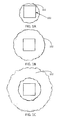
- FIGS. 1A-1C are photomicrographs that show the effects of the beam energy tail on ion beam milling of photoresist.
- the features shown in FIGS 1A-1C were milled using a gold-silicon ion source, with a beam current of 0.2 nA.
- the beam was applied for two seconds to provide a dose of 4 x 10 14 ions per cm 2 .
- the beam was moved in a square pattern to mill a central square 100.
- the ions in the energy tail, having energies away from the peak were deflected differently in the ion column and fell outside the square, milling the photoresist lightly out to circle 102.
- the beam was applied for 10 seconds for a total ion dose of 2 x 10 15 ions per cm 2 .
- the relative number of ions having a particular energy value decreases as the particular energy value is farther from the nominal beam value. That is, the number of ions gets smaller as the energy value gets farther from the nominal value.
- ions having energies farther from the nominal value will also increase in number. The longer the milling operation, the more the effects of ions further in the energy tail will be seen.
- the circle 102 is wider in FIG. 1B than in FIG. 1A because ions further in the tail from the nominal value are having an increased effect because of their increased number.
- the beam was applied for 100 seconds for a total ion dose of 2 x 10 16 ions per cm 2 , and the circle 102 is even wider as the number of ions further away from the nominal energy value increases and the effects are more visible.
- Monochromators are sometimes used to reduce the energy spread of electron beams.
- Monochromators are designed to truncate a symmetrical Gaussian-shaped energy distribution of the electrons in the beam by removing electrons having energies that diverge from the average energy by more than a specified amount.
- Monochromators are complex and typically greatly reduced beam current. Monochromators are therefore not employed in FIB systems used for charged particle beam milling and deposition in commercial applications.
- An object of the invention is to provide a system and method to enhance the beam quality for milling of a liquid metal ion beam by eliminating the low energy tail of the beam.
- Applicants have found that a small number of ions having energy significantly lower than the nominal beam energy contribute disproportionately to the degradation in quality of an ion beam.
- applicants improve the quality of the beam with an unexpectedly small decrease in beam current.
- FIGS. 1A - 1C are photomicrographs showing the effects of the beam energy tail
- FIG. 2 is a graph showing the energy distribution of ions from a liquid metal ion source
- FIG. 3 is a graph using the data of FIG. 2 , but with the x-axis converted to an energy scale with arbitrary positioning of zero and showing the accumulated area under the curve;
- FIG. 4 shows the calculated beam spot size based on chromatic aberration calculations using the energy spread shown in FIGS. 2 and 3 ;
- FIG. 5 shows a dual beam system incorporating a high-pass energy filter in the ion beam column
- FIG. 6 shows an embodiment of a preferred high-pass energy filter
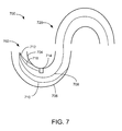
- FIG. 7 shows an alternate embodiment of a high-pass energy filter.
- FIG. 2 shows a graph of a detector signal versus ion energy for a beam of monoisotopic, singly charged gallium ions in a 2.1 ⁇ A ion beam.
- the energies of the ions were measured using a mass spectrometer. Because the mass and charge of the monoisotopic gallium ions is known, the mass spectrometer system could be used to determine the energy of the ions.
- Dots 202 show the background noise of the detector with no extraction voltage on the source, and dots forming curve 201 representing the signal due to the gallium ions.
- FIG. 2 shows that the gallium tail appears to extend about 150 eV below the peak energy value about 275 V.
- FIG. 3 shows the same data 301 as FIG. 2 , but with the zero energy arbitrarily repositioned on the x-axis and with another curve showing the cumulative area 302 under the energy curve to provide another visual representation of the energy spread. From FIG. 3 , it appears that the energy tail extends for at least about 100 eV to the low energy side.
- FIG. 4 shows the calculated beam spot size based on chromatic aberration calculations using the ion energy distribution shown in FIGS. 2 and 3 .
- Dashed line 402 shows the spot diameter of the central beam assuming a Gaussian distribution of energy
- solid line 404 shows the spot size due to the long low energy tail. Line 404 shows that the spot size increases out to 150 nm.
- Elimination of the low energy beam tail would improve the beam quality and reduce undesirable artifacts, such as the circles shown in FIGS 1A-1C . Improved beam quality would improve the quality of milled and deposited features. Elimination of the beam tail would simplify ion beam processing by eliminating clean-up steps, allow the milling and deposition of smaller structures, and generally increasing the ease of use of the FIB system.
- the beam tail extends to such a large extent in the low energy direction, applicants are able to significantly reduce the energy spread by eliminating the low energy beam tail, which only minimally reduces the useful beam current. Because ions in the low energy beam tail did not impact near the ions having energy near the nominal energy value, they do not contribute to the processing speed, and so reduction of the tail in some embodiments has a minimal impact on milling speed or signal to noise ratio in imaging. In a typical gallium liquid metal ion source, applicants have found that only between about 2% and 3.3% of current is in the low energy tail.
- the low energy beam tail can be eliminated using a simple high-pass filter to improve the beam quality to a significant extent while minimally reducing beam current.
- "High-pass filter” is used to include any energy filter that preferentially filters out ions in the low energy beam tail.
- a high-pass filter could pass all ions above a particular energy; it could be a band pass filter having the pass band centered above the peak energy value, so that it passes ions having energies above the peak value while blocking the energy tail; it could be a band pass filter centered on the peak value, but having a pass band sufficiently wide that, because of the asymmetry of the ion energy distribution, it blocks primarily ions in the low energy beam tail, while passing essentially all ions having energies above the peak value.
- FIG. 5 shows a dual beam system 500 including a scanning electron microscope column 502 and an ion beam column 504 that includes a high-pass energy filter 506 for eliminating the low energy beam tail.
- Ion beam column 504 includes an evacuated envelope 510 within which are located an ion source 514, extractor optics 516, a first lens 518, a beam blanker 520, a variable aperture 522, high-pass energy filter 506, beam scanning deflectors 526, and a final lens 528. Ions from source 514 are extracted and formed into a beam by extractor optics 516 and are focused by first lens 518.
- Variable aperture 522 defines the beam diameter and current, and high-pass energy filter 506 removes the low energy ions in the beam tail.
- Beam deflectors 526 scan the beam, focused onto the work piece 530 by final lens 528, in a desired pattern on the surface of work piece 530, which may comprise, for example, a semiconductor device positioned on movable X-Y stage 532 within a lower vacuum chamber 534.
- a gas injector 540 is connected to a supply of process gas 542 to provide a process gas for beam-assisted etching or deposition and a secondary particle detector 544 detects secondary particles for forming an image on a video monitor 546.
- a controller 550 such as a computer, controls the operation of dual beam system 500.
- the ion source 514 is typically a liquid metal ion source that provides a beam of gallium ions, although other ion sources, such as a multicusp or other plasma ion source, can be used, employing for example, oxygen, argon or another noble gas for ions.
- the ion source 514 typically is capable of being focused into a sub-one-tenth micron wide beam at work piece 530 for either modifying the work piece 530 by ion milling, chemically-enhanced etch, material deposition, or for the purpose of imaging the work piece 530. Rather than focusing the beam to a point, the ion column may also provide a shaped beam. Shaped beams can provide larger beam currents to reduce sputtering time.
- a focused ion beam system there are many possible configurations for a focused ion beam system, and the invention is not limited to any particular focused ion beam system.
- a single focusing lens can be used or deflectors 526 may be positioned below final lens 528.
- High-pass energy filter 506 is preferably an electrostatic filter because electrostatic deflection is independent of mass in the non-relativistic limit. Gallium naturally occurs in two isotopes, gallium 69 and gallium 71, and an electrostatic deflector will deflect both by the same amount.
- a magnetic filter can also be used, but is less preferred because it will provide a different trajectory for the different isotopes of gallium. If a magnetic high-pass filter is used, either monoisotopic gallium should be used or an additional magnetic deflector should be provided to reintegrate the beams of gallium of different masses.
- a magnetic filter may also require shielding so that the magnetic field does not affect the trajectory of the ions in other parts of the focusing column. Whatever type of filter is used, it preferably also eliminates neutral gallium atoms in the beam, thereby further improving performance.
- FIG. 6 shows a preferred electrostatic filter.
- Filter 600 includes four sets of deflectors, deflectors 602, deflectors 604, deflectors 606, and deflectors 608. Ions of all energy levels enter deflector 602 along its optical axis. Higher energy ions move faster and spend less time in the deflection field between the deflectors, so they are deflected slightly less than ions having lower energy.
- FIG. 6 shows trajectories of ions having three representative energy levels: a first trajectory 610 for ions having a nominal energy qV, and a second trajectory 612 for ions having energy q(V+dV), and a third trajectory 614 for ions having an energy of q(V-dV).
- Deflector 604 deflects ions having energy qV back onto a trajectory that is essentially parallel to the original trajectory as shown by trajectory 610. Ions having energies of q(V+dV), being deflected less, are deflected to trajectory 612 that is not quite parallel to the original trajectory. Ion having energy less than q(V-dV), being deflected more, are deflected to trajectory 614 that is not quite parallel to the original trajectory, and are deflected just enough to clear a barrier 616. Ions having energy of less than q(V-dV) are not deflected enough to clear barrier 616, and so they hit the barrier and are not transmitted through the filter.
- Filter 600 is a "high-pass" filter because ions having energy greater than q(V-dV) can pass through the filter, but ions having energy less than q(V-dV) do not pass through the filter.
- the energy of ions that are passed can be adjusted by moving the barrier 616 closer or further from the optical axis or by changing the deflection voltages.
- Barrier 616 will be damaged by the impact of the ions, so the filter is preferably positioned close to the source where the ion energy is relatively low to reduce sputtering, and barrier 616 is preferably composed of a material, such as carbon or tungsten, that is resistant to sputtering.
- Deflector 606 deflects the ions back toward the deflector 608, which deflects the ions back onto a trajectory that is essentially parallel to the trajectory of the ions before they entered the filter 600. Ions having energies slightly different from qV will end up with trajectories that are not quite parallel to the original trajectory, and the filter 600 may cause astigmatism of the beam, which can be corrected, if necessary, using known techniques, such as an octupole lens. While deflectors 602, 604, 606, and 608 are shown as simple parallel plates, any type of deflector, such as quadrapoles, sextupoles, or octupoles can be used.
- the nominal ion energy is 30 keV and the ion voltages on the deflectors 602, 604, 606, and 608 are typically in the range of 0-250V, respectively.
- the optimum positioning of barrier 616 can be readily determined experimentally for any particular application by observing the change in ion current and observing the milling results on a surface as the position of barrier 616 is moved towards or away from the optical axis.
- Barrier 616 is preferably positioned sufficiently close to the optical axis to reduce or eliminate the effects of the beam energy tail, while minimally reducing overall current.
- FIG. 7 shows another design for a high-pass filter 700.
- the high-pass filter of FIG. 7 is based on uses a hemispherical capacitor, which is described, for example, in " Design of Retarding Fields Energy Analyzers" The Review of Scientific Instruments, Vol. 32, No. 12 (1961 pp 1283-93 ).
- High-pass filter 700 includes a first hemispherical filter 702 having an inner hemispherical conductor 704 and an outer hemispherical conductor 706. An electric potential difference is maintained between the inner and outer hemispherical conductors. The field between the conductors causes charged particles to curve within the filter and only particles within an energy band will pass through the filter.
- first hemispherical filter 702 Within first hemispherical filter 702 is a particle blocker 714 that can be used to block particles that would other wise pass through the hemispherical filter 702, thereby asymmetrically altering the pass band to preferentially block ions having energies that are a specified amount below the peak energy value.
- Trajectory 716 shows the path of an ion that would have passed through filter 702 had it not been blocked by particle blocker 714.
- the first hemispherical filter 702 could be tuned so that ions having energies within a broad range centered about the energy peak of an ion beam would pass through the filter.
- the filter would pass essentially all of the ions in the beam.
- Particle blocker 714 then blocks ions having energies below a specified value to eliminate the low energy ion tail. That is, the pass band of the hemispherical filter 702 is very broad, and the blocker 714 essentially turns the hemispherical filter 702 into a high-pass filter by preferentially blocking low energy ions.
- the hemispherical filter 702 can be tuned so that the center of the pass band is well above the energy peak of the beam.
- the filter can thus block off the tail of low energy ions, which will be outside of the pass band, while passing essentially all ions above the energy peak of the beam.
- the energy pass band of the filter is essentially centered on the beam peak energy value, with the band wide enough to pass essentially all ions above the beam peak energy, blocking only the extended beam tail at lower energies.
- a filter is not technically a high-pass filter, it will be within the definition of a high-pass filter as used herein because it blocks more low energy ions than high energy ions, preferably passing essentially all of the ions in the beam above the energy peak value, while blocking the low energy tail.
- first hemispherical filter 702 When the charged particles leave first hemispherical filter 702, they are moving in the opposite direction of the direction in which they entered filter 702.
- a second hemispherical capacitor 720 can be used to change the direction of the charged particles back to the direction in which the ions were originally moving.
- the second hemispherical filter can also be used as a filter.
- the voltages on the hemispherical filters for a particular nominal beam energy can be readily determined by skilled persons.
- the preferred ion energy passed by the filter in the various embodiments of the invention will depend on the application. For example, for gross machining, it will be desired to pass more ions and the chromatic aberration will be less important. For fine micromachining, the pass energy may be set closer to the nominal value. For example, in some embodiments, the pass energy may be set to be 2.5 eV, 3 eV, 4 eV, 5 eV, 6 eV, 10 eV, 25 eV, 50 eV, or 75 eV below the nominal beam energy.
- the filter is preferably set to block ions having energies less than the peak value minus 2.5 eV, 3 eV, 4 eV, 5 eV, 6 eV, 10 eV, 25 eV, 50 eV, or 75 eV.
- the high pass filter preferably blocks more ions having energies below the peak value than ions having energies above the peak value.
- a high-pass filter may filter out more than 1%, more than 2%, or more than 3% of ions below the beam energy peak while blocking less than 2%, less than 1%, less that 0.5%, or less than 0.25% of ions having energies above the peak value.
- Various embodiments may use any combination of the recited values for blocking low energy ions and passing high energy ions.
- the filter may block more than 1% of ions having energies below the nominal value and less than 0.5% of the ions having energies above the nominal value.
- the high-pass filter may block ions in the beam having less than a specified energy and passing essentially all ions having energies greater than the specified energy, the specified value being below the peak energy value of ion beam. In some preferred embodiments, the high-pass filter blocks more than 1%, more than 2%, or more than 3% of the total number of ions in the beam.
- Preferred embodiments of the focused ion beam system of the present invention include a source of ions; an extractor electrode for extracting ions from the source and forming the ions into a beam; a high-pass filter for blocking ions in the beam having less than a specified energy and passing essentially all ions having energies greater than the specified energy, the specified value being below the peak energy value of the ion beam; a deflector for positioning the ion beam on the sample; and a focusing lens for focusing the ions onto a submicron spot on the sample.
- Preferred embodiments of the high-pass filter remove ions having energies of less than the energy value of the energy peak of the beam minus 4 eV, minus 6 eV, or more preferably minus 10 eV.
- Preferred embodiments of the high-pass filter of the present invention include an electrostatic deflector, in which the high-pass filter preferably includes at least four electrostatic deflectors.
- the high-pass filter include a hemispherical filter, a magnetic deflector, or a band pass filter in which the pass band preferably passes essentially all ions having energies above the energy peak of the beam.
- Preferred embodiments of the high-pass filter block more than 2% of ions having energy less than the peak value and less than 1% of the ions having energies above the peak value, and more preferably blocks more than 3% of ions having energy less than the peak value, and less than 2% of the ions having energies above the peak value,.
- Preferred embodiments of a focused ion beam system of the present invention may include a source of ions, the source producing ions having different energies and forming the ions into a beam, the energies centered around a peak energy and having a low energy tail; an energy filter for blocking ions having less energy than a specified energy value that is below the energy peak, the energy filter preferentially blocking ions in the low energy ion tail and passing ions having energies above the energy peak; a deflector for positioning the ion beam on the sample; and a focusing lens for focusing the ions onto a submicron spot on the sample.
- Preferred embodiments of the focused ion beam system include an energy filter blocks more than 2% of the ions below the beam peak energy and less than 1% of the ions above the beam peak, and more preferably blocks more than 1.5% of the ions below the beam peak energy and less than 0.5% of the ions above the beam peak.
- Preferred embodiments of the energy filter pass ions having energies in an energy range that is not symmetrical about the peak energy of the beam, the energy range extending further above the energy peak than below the energy peak.
- Preferred embodiments of the present invention for improving the beam quality of a focused ion beam system includes emitting ions from an ion source and forming the ions into a beam, the distribution of ion energies in the beam being unsymmetrical about a peak value, the distribution including more ions having energy values below the peak energy value than ions having energies above the peak energy value; filtering a greater number of having energies below the peak value than ions having energies above the peak value; and focusing the remaining ions onto a sample.
- Preferred embodiments for filtering ions includes filtering ions in a beam in which a greater number of ions in the beam have energies below the peak value than ions having energies above the peak value, and passing essentially all ions in the beam having energies above the peak value while blocking ions having energies that deviate by a specified amount below the peak energy value.
- Preferred embodiments for filtering ions include deflecting the ions multiple times, the ions having energies below the specified deviation from the energy peak being deflected insufficiently to pass a barrier.
- Preferred embodiments for filtering ions include filtering ions having energies of less than the peak energy minus 4 eV, or more preferably minus 6 eV.
Landscapes
- Chemical & Material Sciences (AREA)
- Analytical Chemistry (AREA)
- Physics & Mathematics (AREA)
- Engineering & Computer Science (AREA)
- Plasma & Fusion (AREA)
- Electron Sources, Ion Sources (AREA)
- Physical Vapour Deposition (AREA)
Abstract
Description
- The present invention relates to an improved particle beam device, such as a focused ion beam (FIB), and more particularly to an energy filter for improving beam quality and milling quality in such a device.
- In focused ion beam (FIB) systems, ions are extracted from a source, formed into a beam, focused, and scanned across a substrate to form an image of a feature, to mill a feature or to deposit material from a gas ambient. As features become increasingly small, the FIB system must be optimized to provide a higher quality beam, that is, a smaller, more focused beam spot in which the distribution of current should be as compact as possible.
- Several factors reduce the quality of the current distribution of the FIB. For ion columns using a liquid metal ion source (LMIS), a primary cause of reduced beam quality at low to moderate beam current is chromatic aberration. Gallium ions emitted from a liquid metal ion source have an energy distribution which is a combination of the intrinsic and particle interactions; the latter component is commonly referred to the as the Boersch affect. The former is very complicated as there are several different mechanisms to form the ions. Chromatic aberration is the result of particles of different energies being focused at different locations by the lenses in the ion column. The chromatic aberration causes the beam current distribution to vary with the energy spread (ΔE) of the ions. If the energies of the ions in an ion beam were plotted on a histogram showing the frequency of occurrence of ions at each energy value, the graph would have a peak at a "nominal" energy value, decrease rapidly for energies above and below the peak, and then taper off more slowly. The regions where the graph tapers off are known as the beam "tail." The energy spread, ΔE, is typically measured as the "full width, half maximum," that is, the energy between points at half the maximum peak value on either side of the peak. In a typical gallium liquid metal ion source, the energy spread in the beam having a current of 1 pA to several hundred nA is typically about 5 eV at an emission current of 1.5 to 2.5 µA from the source.
-
FIGS. 1A-1C are photomicrographs that show the effects of the beam energy tail on ion beam milling of photoresist. The features shown inFIGS 1A-1C were milled using a gold-silicon ion source, with a beam current of 0.2 nA. InFIG. 1A , the beam was applied for two seconds to provide a dose of 4 x 10¹⁴ ions per cm2. The beam was moved in a square pattern to mill acentral square 100. The ions in the energy tail, having energies away from the peak were deflected differently in the ion column and fell outside the square, milling the photoresist lightly out to circle 102. - In
FIG. 1B , the beam was applied for 10 seconds for a total ion dose of 2 x 10¹⁵ ions per cm2. The relative number of ions having a particular energy value decreases as the particular energy value is farther from the nominal beam value. That is, the number of ions gets smaller as the energy value gets farther from the nominal value. As the total number of ions is increased, however, ions having energies farther from the nominal value will also increase in number. The longer the milling operation, the more the effects of ions further in the energy tail will be seen. Thecircle 102 is wider inFIG. 1B than inFIG. 1A because ions further in the tail from the nominal value are having an increased effect because of their increased number. InFIG. 1C , the beam was applied for 100 seconds for a total ion dose of 2 x 10¹⁶ ions per cm2, and thecircle 102 is even wider as the number of ions further away from the nominal energy value increases and the effects are more visible. - Monochromators are sometimes used to reduce the energy spread of electron beams. Monochromators are designed to truncate a symmetrical Gaussian-shaped energy distribution of the electrons in the beam by removing electrons having energies that diverge from the average energy by more than a specified amount. Monochromators are complex and typically greatly reduced beam current. Monochromators are therefore not employed in FIB systems used for charged particle beam milling and deposition in commercial applications.
- An object of the invention is to provide a system and method to enhance the beam quality for milling of a liquid metal ion beam by eliminating the low energy tail of the beam. Applicants have found that a small number of ions having energy significantly lower than the nominal beam energy contribute disproportionately to the degradation in quality of an ion beam. By using a relatively simple high-pass energy filter, applicants improve the quality of the beam with an unexpectedly small decrease in beam current.
- The foregoing has outlined rather broadly the features and technical advantages of the present invention in order that the detailed description of the invention that follows may be better understood. Additional features and advantages of the invention will be described hereinafter. It should be appreciated by those skilled in the art that the conception and specific embodiments disclosed may be readily utilized as a basis for modifying or designing other structures for carrying out the same purposes of the present invention. It should also be realized by those skilled in the art that such equivalent constructions do not depart from the spirit and scope of the invention as set forth in the appended claims.
- For a more thorough understanding of the present invention, and advantages thereof, reference is now made to the following descriptions taken in conjunction with the accompanying drawings, in which:
-
FIGS. 1A - 1C are photomicrographs showing the effects of the beam energy tail; -
FIG. 2 is a graph showing the energy distribution of ions from a liquid metal ion source; -
FIG. 3 is a graph using the data ofFIG. 2 , but with the x-axis converted to an energy scale with arbitrary positioning of zero and showing the accumulated area under the curve; -
FIG. 4 shows the calculated beam spot size based on chromatic aberration calculations using the energy spread shown inFIGS. 2 and 3 ; -
FIG. 5 shows a dual beam system incorporating a high-pass energy filter in the ion beam column; -
FIG. 6 shows an embodiment of a preferred high-pass energy filter; and -
FIG. 7 shows an alternate embodiment of a high-pass energy filter. - Applicants measured the energy values of ions in an ion beam to determine their energy distribution.
FIG. 2 shows a graph of a detector signal versus ion energy for a beam of monoisotopic, singly charged gallium ions in a 2.1 µA ion beam. The energies of the ions were measured using a mass spectrometer. Because the mass and charge of the monoisotopic gallium ions is known, the mass spectrometer system could be used to determine the energy of the ions.Dots 202 show the background noise of the detector with no extraction voltage on the source, anddots forming curve 201 representing the signal due to the gallium ions.FIG. 2 shows that the gallium tail appears to extend about 150 eV below the peak energy value about 275 V.FIG. 3 shows thesame data 301 asFIG. 2 , but with the zero energy arbitrarily repositioned on the x-axis and with another curve showing thecumulative area 302 under the energy curve to provide another visual representation of the energy spread. FromFIG. 3 , it appears that the energy tail extends for at least about 100 eV to the low energy side. - This spread in ion energy will affect the ability of the column optics to focus the beam, particularly the low energy beam tail.
FIG. 4 shows the calculated beam spot size based on chromatic aberration calculations using the ion energy distribution shown inFIGS. 2 and 3 . Dashedline 402 shows the spot diameter of the central beam assuming a Gaussian distribution of energy, andsolid line 404 shows the spot size due to the long low energy tail.Line 404 shows that the spot size increases out to 150 nm. - Elimination of the low energy beam tail would improve the beam quality and reduce undesirable artifacts, such as the circles shown in
FIGS 1A-1C . Improved beam quality would improve the quality of milled and deposited features. Elimination of the beam tail would simplify ion beam processing by eliminating clean-up steps, allow the milling and deposition of smaller structures, and generally increasing the ease of use of the FIB system. - By discovering that the beam tail extends to such a large extent in the low energy direction, applicants are able to significantly reduce the energy spread by eliminating the low energy beam tail, which only minimally reduces the useful beam current. Because ions in the low energy beam tail did not impact near the ions having energy near the nominal energy value, they do not contribute to the processing speed, and so reduction of the tail in some embodiments has a minimal impact on milling speed or signal to noise ratio in imaging. In a typical gallium liquid metal ion source, applicants have found that only between about 2% and 3.3% of current is in the low energy tail.
- The low energy beam tail can be eliminated using a simple high-pass filter to improve the beam quality to a significant extent while minimally reducing beam current. "High-pass filter" is used to include any energy filter that preferentially filters out ions in the low energy beam tail. In the context of the present invention, a high-pass filter could pass all ions above a particular energy; it could be a band pass filter having the pass band centered above the peak energy value, so that it passes ions having energies above the peak value while blocking the energy tail; it could be a band pass filter centered on the peak value, but having a pass band sufficiently wide that, because of the asymmetry of the ion energy distribution, it blocks primarily ions in the low energy beam tail, while passing essentially all ions having energies above the peak value.
-
FIG. 5 shows adual beam system 500 including a scanningelectron microscope column 502 and anion beam column 504 that includes a high-pass energy filter 506 for eliminating the low energy beam tail. Any known type of high-pass energy filter can be used.Ion beam column 504 includes an evacuatedenvelope 510 within which are located anion source 514,extractor optics 516, afirst lens 518, abeam blanker 520, avariable aperture 522, high-pass energy filter 506,beam scanning deflectors 526, and afinal lens 528. Ions fromsource 514 are extracted and formed into a beam byextractor optics 516 and are focused byfirst lens 518.Variable aperture 522 defines the beam diameter and current, and high-pass energy filter 506 removes the low energy ions in the beam tail. Beam deflectors 526 scan the beam, focused onto thework piece 530 byfinal lens 528, in a desired pattern on the surface ofwork piece 530, which may comprise, for example, a semiconductor device positioned on movableX-Y stage 532 within alower vacuum chamber 534. Agas injector 540 is connected to a supply ofprocess gas 542 to provide a process gas for beam-assisted etching or deposition and asecondary particle detector 544 detects secondary particles for forming an image on avideo monitor 546. Acontroller 550, such as a computer, controls the operation ofdual beam system 500. - The
ion source 514 is typically a liquid metal ion source that provides a beam of gallium ions, although other ion sources, such as a multicusp or other plasma ion source, can be used, employing for example, oxygen, argon or another noble gas for ions. Theion source 514 typically is capable of being focused into a sub-one-tenth micron wide beam atwork piece 530 for either modifying thework piece 530 by ion milling, chemically-enhanced etch, material deposition, or for the purpose of imaging thework piece 530. Rather than focusing the beam to a point, the ion column may also provide a shaped beam. Shaped beams can provide larger beam currents to reduce sputtering time. - Skilled persons will recognize that there are many possible configurations for a focused ion beam system, and the invention is not limited to any particular focused ion beam system. For example, a single focusing lens can be used or
deflectors 526 may be positioned belowfinal lens 528. - High-
pass energy filter 506 is preferably an electrostatic filter because electrostatic deflection is independent of mass in the non-relativistic limit. Gallium naturally occurs in two isotopes, gallium 69 and gallium 71, and an electrostatic deflector will deflect both by the same amount. A magnetic filter can also be used, but is less preferred because it will provide a different trajectory for the different isotopes of gallium. If a magnetic high-pass filter is used, either monoisotopic gallium should be used or an additional magnetic deflector should be provided to reintegrate the beams of gallium of different masses. A magnetic filter may also require shielding so that the magnetic field does not affect the trajectory of the ions in other parts of the focusing column. Whatever type of filter is used, it preferably also eliminates neutral gallium atoms in the beam, thereby further improving performance. -
FIG. 6 shows a preferred electrostatic filter.Filter 600 includes four sets of deflectors,deflectors 602,deflectors 604,deflectors 606, anddeflectors 608. Ions of all energy levels enterdeflector 602 along its optical axis. Higher energy ions move faster and spend less time in the deflection field between the deflectors, so they are deflected slightly less than ions having lower energy.FIG. 6 shows trajectories of ions having three representative energy levels: afirst trajectory 610 for ions having a nominal energy qV, and asecond trajectory 612 for ions having energy q(V+dV), and athird trajectory 614 for ions having an energy of q(V-dV). -
Deflector 604 deflects ions having energy qV back onto a trajectory that is essentially parallel to the original trajectory as shown bytrajectory 610. Ions having energies of q(V+dV), being deflected less, are deflected totrajectory 612 that is not quite parallel to the original trajectory. Ion having energy less than q(V-dV), being deflected more, are deflected totrajectory 614 that is not quite parallel to the original trajectory, and are deflected just enough to clear abarrier 616. Ions having energy of less than q(V-dV) are not deflected enough toclear barrier 616, and so they hit the barrier and are not transmitted through the filter. -
Filter 600 is a "high-pass" filter because ions having energy greater than q(V-dV) can pass through the filter, but ions having energy less than q(V-dV) do not pass through the filter. The energy of ions that are passed can be adjusted by moving thebarrier 616 closer or further from the optical axis or by changing the deflection voltages. -
Barrier 616 will be damaged by the impact of the ions, so the filter is preferably positioned close to the source where the ion energy is relatively low to reduce sputtering, andbarrier 616 is preferably composed of a material, such as carbon or tungsten, that is resistant to sputtering. -
Deflector 606 deflects the ions back toward thedeflector 608, which deflects the ions back onto a trajectory that is essentially parallel to the trajectory of the ions before they entered thefilter 600. Ions having energies slightly different from qV will end up with trajectories that are not quite parallel to the original trajectory, and thefilter 600 may cause astigmatism of the beam, which can be corrected, if necessary, using known techniques, such as an octupole lens. Whiledeflectors - For example, in one preferred embodiment, the nominal ion energy is 30 keV and the ion voltages on the
deflectors barrier 616 can be readily determined experimentally for any particular application by observing the change in ion current and observing the milling results on a surface as the position ofbarrier 616 is moved towards or away from the optical axis.Barrier 616 is preferably positioned sufficiently close to the optical axis to reduce or eliminate the effects of the beam energy tail, while minimally reducing overall current. -
FIG. 7 shows another design for a high-pass filter 700. The high-pass filter ofFIG. 7 is based on uses a hemispherical capacitor, which is described, for example, in "Design of Retarding Fields Energy Analyzers" The Review of Scientific Instruments, Vol. 32, No. 12 (1961 pp 1283-93). High-pass filter 700 includes a firsthemispherical filter 702 having an innerhemispherical conductor 704 and an outerhemispherical conductor 706. An electric potential difference is maintained between the inner and outer hemispherical conductors. The field between the conductors causes charged particles to curve within the filter and only particles within an energy band will pass through the filter. - Charged particles having energies within the pass band will follow a trajectory such as
trajectory 708. Charged particles having energies greater than high end of the energy pass band would follow a trajectory such astrajectory 710 and spiral into the outerhemispherical conductor 706. Charged particles having energies below the energy pass band will follow a trajectory such astrajectory 712 and spiral into the innerhemispherical conductor 704. Within firsthemispherical filter 702 is aparticle blocker 714 that can be used to block particles that would other wise pass through thehemispherical filter 702, thereby asymmetrically altering the pass band to preferentially block ions having energies that are a specified amount below the peak energy value.Trajectory 716 shows the path of an ion that would have passed throughfilter 702 had it not been blocked byparticle blocker 714. - The first
hemispherical filter 702 could be tuned so that ions having energies within a broad range centered about the energy peak of an ion beam would pass through the filter. Thus, in the absence ofparticle blocker 714, the filter would pass essentially all of the ions in the beam.Particle blocker 714 then blocks ions having energies below a specified value to eliminate the low energy ion tail. That is, the pass band of thehemispherical filter 702 is very broad, and theblocker 714 essentially turns thehemispherical filter 702 into a high-pass filter by preferentially blocking low energy ions. In an alternative embodiment that does not require aparticle blocker 714, thehemispherical filter 702 can be tuned so that the center of the pass band is well above the energy peak of the beam. The filter can thus block off the tail of low energy ions, which will be outside of the pass band, while passing essentially all ions above the energy peak of the beam. In yet another embodiment, the energy pass band of the filter is essentially centered on the beam peak energy value, with the band wide enough to pass essentially all ions above the beam peak energy, blocking only the extended beam tail at lower energies. While such a filter is not technically a high-pass filter, it will be within the definition of a high-pass filter as used herein because it blocks more low energy ions than high energy ions, preferably passing essentially all of the ions in the beam above the energy peak value, while blocking the low energy tail. - When the charged particles leave first
hemispherical filter 702, they are moving in the opposite direction of the direction in which they enteredfilter 702. A secondhemispherical capacitor 720 can be used to change the direction of the charged particles back to the direction in which the ions were originally moving. The second hemispherical filter can also be used as a filter. The voltages on the hemispherical filters for a particular nominal beam energy can be readily determined by skilled persons. - The preferred ion energy passed by the filter in the various embodiments of the invention will depend on the application. For example, for gross machining, it will be desired to pass more ions and the chromatic aberration will be less important. For fine micromachining, the pass energy may be set closer to the nominal value. For example, in some embodiments, the pass energy may be set to be 2.5 eV, 3 eV, 4 eV, 5 eV, 6 eV, 10 eV, 25 eV, 50 eV, or 75 eV below the nominal beam energy. That is, the filter is preferably set to block ions having energies less than the peak value minus 2.5 eV, 3 eV, 4 eV, 5 eV, 6 eV, 10 eV, 25 eV, 50 eV, or 75 eV.
- Because of the low energy beam tail, the high pass filter preferably blocks more ions having energies below the peak value than ions having energies above the peak value. In some embodiments, a high-pass filter may filter out more than 1%, more than 2%, or more than 3% of ions below the beam energy peak while blocking less than 2%, less than 1%, less that 0.5%, or less than 0.25% of ions having energies above the peak value. Various embodiments may use any combination of the recited values for blocking low energy ions and passing high energy ions. For example, the filter may block more than 1% of ions having energies below the nominal value and less than 0.5% of the ions having energies above the nominal value. In some embodiments, the high-pass filter may block ions in the beam having less than a specified energy and passing essentially all ions having energies greater than the specified energy, the specified value being below the peak energy value of ion beam. In some preferred embodiments, the high-pass filter blocks more than 1%, more than 2%, or more than 3% of the total number of ions in the beam.
- Preferred embodiments of the focused ion beam system of the present invention include a source of ions; an extractor electrode for extracting ions from the source and forming the ions into a beam; a high-pass filter for blocking ions in the beam having less than a specified energy and passing essentially all ions having energies greater than the specified energy, the specified value being below the peak energy value of the ion beam; a deflector for positioning the ion beam on the sample; and a focusing lens for focusing the ions onto a submicron spot on the sample. Preferred embodiments of the high-pass filter remove ions having energies of less than the energy value of the energy peak of the beam minus 4 eV, minus 6 eV, or more preferably minus 10 eV.
- Preferred embodiments of the high-pass filter of the present invention include an electrostatic deflector, in which the high-pass filter preferably includes at least four electrostatic deflectors. Other preferred embodiments the high-pass filter include a hemispherical filter, a magnetic deflector, or a band pass filter in which the pass band preferably passes essentially all ions having energies above the energy peak of the beam. Preferred embodiments of the high-pass filter block more than 2% of ions having energy less than the peak value and less than 1% of the ions having energies above the peak value, and more preferably blocks more than 3% of ions having energy less than the peak value, and less than 2% of the ions having energies above the peak value,.
- Preferred embodiments of a focused ion beam system of the present invention may include a source of ions, the source producing ions having different energies and forming the ions into a beam, the energies centered around a peak energy and having a low energy tail; an energy filter for blocking ions having less energy than a specified energy value that is below the energy peak, the energy filter preferentially blocking ions in the low energy ion tail and passing ions having energies above the energy peak; a deflector for positioning the ion beam on the sample; and a focusing lens for focusing the ions onto a submicron spot on the sample. Preferred embodiments of the focused ion beam system include an energy filter blocks more than 2% of the ions below the beam peak energy and less than 1% of the ions above the beam peak, and more preferably blocks more than 1.5% of the ions below the beam peak energy and less than 0.5% of the ions above the beam peak. Preferred embodiments of the energy filter pass ions having energies in an energy range that is not symmetrical about the peak energy of the beam, the energy range extending further above the energy peak than below the energy peak.
- Preferred embodiments of the present invention for improving the beam quality of a focused ion beam system, includes emitting ions from an ion source and forming the ions into a beam, the distribution of ion energies in the beam being unsymmetrical about a peak value, the distribution including more ions having energy values below the peak energy value than ions having energies above the peak energy value; filtering a greater number of having energies below the peak value than ions having energies above the peak value; and focusing the remaining ions onto a sample. Preferred embodiments for filtering ions includes filtering ions in a beam in which a greater number of ions in the beam have energies below the peak value than ions having energies above the peak value, and passing essentially all ions in the beam having energies above the peak value while blocking ions having energies that deviate by a specified amount below the peak energy value. Preferred embodiments for filtering ions include deflecting the ions multiple times, the ions having energies below the specified deviation from the energy peak being deflected insufficiently to pass a barrier. Preferred embodiments for filtering ions include filtering ions having energies of less than the peak energy minus 4 eV, or more preferably minus 6 eV.
- Although the present invention and its advantages have been described in detail, it should be understood that various changes, substitutions and alterations can be made to the embodiments described herein without departing from the spirit and scope of the invention as defined by the appended claims. Moreover, the scope of the present application is not intended to be limited to the particular embodiments of the process, machine, manufacture, composition of matter, means, methods and steps described in the specification. As one of ordinary skill in the art will readily appreciate from the disclosure of the present invention, processes, machines, manufacture, compositions of matter, means, methods, or steps, presently existing or later to be developed that perform substantially the same function or achieve substantially the same result as the corresponding embodiments described herein may be utilized according to the present invention. Accordingly, the appended claims are intended to include within their scope such processes, machines, manufacture, compositions of matter, means, methods, or steps.
Claims (15)
- A focused ion beam system (500) for processing a sample (530), comprising:a source of ions (514);an extractor electrode (516) for extracting ions from the source and forming the ions into a beam;a deflector (526) for positioning the ion beam on the sample; anda focusing lens (528) for focusing the ions onto a submicron spot on the sample, characterized by:a high-pass filter (506, 600) for blocking ions in the beam having less than a specified energy and passing essentially all ions having energies greater than the specified energy, the specified value being below the peak energy value of the ion beam
- The focused ion beam system of claim 1 in which the high-pass filter removes ions having energies of less than the energy value of the energy peak of the beam minus 4 eV.
- The focused ion beam system of claim 1 in which the high-pass filter removes ions having energies of less than the energy value of the energy peak of the beam minus 6 eV.
- The focused ion beam system of claim 1 in which the high-pass filter removes ions having energies of less than the energy value of the energy peak of the beam minus 10 eV.
- The focused ion beam system of any of the above claims in which the high-pass filter comprises an electrostatic deflector.
- The focused ion beam system of claim 5 in which the high-pass filter comprises at least four electrostatic deflectors (602, 604, 606, 608).
- The focused ion beam system of any of claims 5 or 6 in which the high-pass filter comprises a hemispherical filter.
- The focused ion beam system of claims 5 or 2 in which the high-pass filter comprises a magnetic deflector.
- The focused ion beam system of any of the above claims in which the high-pass filter comprises a band pass filter, the pass band passing essentially all ions having energies above the energy peak of the beam.
- The focused ion beam system of claim 1 in which the high-pass filter blocks more than 2% of ions having energy less than the peak value and less than 1% of the ions having energies above the peak value,.
- The focused ion beam system of claim 1 in which the high-pass filter blocks more than 3% of ions having energy less than the peak value, and less than 2% of the ions having energies above the peak value,.
- A method of improving the beam quality of a focused ion beam system (500), comprising:emitting ions from an ion source (514) and forming the ions into a beam, the distribution of ion energies in the beam being unsymmetrical about a peak value, the distribution including more ions having energy values below the peak energy value than ions having energies above the peak energy value;characterized by:filtering a greater number of having energies below the peak value than ions having energies above the peak value; andfocusing the remaining ions onto a sample (530).
- The method of claim 12 in which filtering ions includes filtering ions a greater number of having energies below the peak value than ions having energies above the peak value includes passing essentially all ions in the beam having energies above the peak value while blocking ions having energies that deviate by a specified amount below the peak energy value.
- The method of any of claims 12 or 13 in which filtering ions includes deflecting the ions multiple times, the ions having energies below the specified deviation from the energy peak being deflected insufficiently to pass a barrier.
- The method of any of claims 12 through 14 in which filtering ions includes filtering ions having energies of less than the peak energy minus 4 eV.
Applications Claiming Priority (1)
| Application Number | Priority Date | Filing Date | Title |
|---|---|---|---|
| US12/494,024 US8053725B2 (en) | 2009-06-29 | 2009-06-29 | Beam quality in FIB systems |
Publications (3)
| Publication Number | Publication Date |
|---|---|
| EP2270837A2 true EP2270837A2 (en) | 2011-01-05 |
| EP2270837A3 EP2270837A3 (en) | 2011-04-06 |
| EP2270837B1 EP2270837B1 (en) | 2015-08-12 |
Family
ID=42670348
Family Applications (1)
| Application Number | Title | Priority Date | Filing Date |
|---|---|---|---|
| EP10167436.4A Not-in-force EP2270837B1 (en) | 2009-06-29 | 2010-06-28 | Improvement of beam quality in FIB systems |
Country Status (3)
| Country | Link |
|---|---|
| US (1) | US8053725B2 (en) |
| EP (1) | EP2270837B1 (en) |
| JP (1) | JP5820552B2 (en) |
Cited By (1)
| Publication number | Priority date | Publication date | Assignee | Title |
|---|---|---|---|---|
| EP2592642A3 (en) * | 2011-11-08 | 2015-08-26 | Fei Company | Charged particle energy filter |
Families Citing this family (6)
| Publication number | Priority date | Publication date | Assignee | Title |
|---|---|---|---|---|
| EP2211366B1 (en) * | 2009-01-23 | 2011-10-19 | ICT, Integrated Circuit Testing Gesellschaft für Halbleiterprüftechnik mbH | High resolution gas field ion column |
| US9105438B2 (en) | 2012-05-31 | 2015-08-11 | Fei Company | Imaging and processing for plasma ion source |
| US9767984B2 (en) * | 2014-09-30 | 2017-09-19 | Fei Company | Chicane blanker assemblies for charged particle beam systems and methods of using the same |
| US9685298B1 (en) * | 2016-02-01 | 2017-06-20 | Varian Semiconductor Equipment Associates, Inc. | Apparatus and method for contamination control in ion beam apparatus |
| EP3196919B1 (en) * | 2016-10-20 | 2018-09-19 | FEI Company | Cryogenic specimen processing in a charged particle microscope |
| NL2035939B1 (en) | 2023-10-02 | 2025-04-10 | Univ Delft Tech | Energy filter, device comprising an energy filter, and method for filtering a charged particle beam |
Family Cites Families (20)
| Publication number | Priority date | Publication date | Assignee | Title |
|---|---|---|---|---|
| JPS61188843A (en) | 1985-02-15 | 1986-08-22 | Hitachi Ltd | mass separator |
| JPH04147978A (en) * | 1990-10-11 | 1992-05-21 | Seiko Instr Inc | Formation of film by cvd with ion beam |
| JPH05129001A (en) * | 1991-11-06 | 1993-05-25 | Anelva Corp | Ion analyzer |
| JP2731886B2 (en) * | 1993-04-27 | 1998-03-25 | ▲巌▼ 大泊 | Single ion implanter and method |
| EP0647960B1 (en) * | 1993-05-21 | 1997-03-26 | Koninklijke Philips Electronics N.V. | Energy filter with correction of a second-order chromatic aberration |
| EP0840939B1 (en) * | 1996-05-21 | 2005-08-03 | Fei Company | Correction device for the correction of lens aberrations in particle-optical apparatus |
| DE69733408T2 (en) * | 1996-09-20 | 2005-11-10 | Fei Co., Hillsboro | CORRECTION DEVICE FOR CORRECTION CHROMATIC ERROR IN A PARTICLE OPTICAL DEVICE |
| WO1999030342A1 (en) * | 1997-12-11 | 1999-06-17 | Philips Electron Optics B.V. | Correction device for correcting the spherical aberration in particle-optical apparatus |
| JP4286913B2 (en) * | 1997-12-22 | 2009-07-01 | エフ イー アイ カンパニ | Correction device for correcting chromatic aberration in particle optical equipment |
| US6410924B1 (en) * | 1999-11-16 | 2002-06-25 | Schlumberger Technologies, Inc. | Energy filtered focused ion beam column |
| FR2804246B1 (en) | 2000-01-21 | 2003-09-19 | X Ion | ION LITHOGRAPHY PROCESS, HIGH CONTRAST COATING, EQUIPMENT AND RETICLE FOR IMPLEMENTATION |
| JP2001357809A (en) * | 2000-04-10 | 2001-12-26 | Jeol Ltd | Monochromator for electron beam |
| US6501076B1 (en) * | 2000-10-11 | 2002-12-31 | Fei Company | Electron analyzer having an integrated low pass filter |
| US20030143327A1 (en) * | 2001-12-05 | 2003-07-31 | Rudiger Schlaf | Method for producing a carbon nanotube |
| JP4362569B2 (en) * | 2002-12-11 | 2009-11-11 | 独立行政法人 日本原子力研究開発機構 | Pencil type ion beam forming method for high precision 3D irradiation |
| US7378667B2 (en) * | 2005-04-05 | 2008-05-27 | Fei Company | Particle-optical appliance provided with aberration-correcting means |
| EP1783811A3 (en) * | 2005-11-02 | 2008-02-27 | FEI Company | Corrector for the correction of chromatic aberrations in a particle-optical apparatus |
| DE102007024353B4 (en) * | 2007-05-24 | 2009-04-16 | Ceos Corrected Electron Optical Systems Gmbh | Monochromator and beam source with monochromator |
| EP2128885A1 (en) * | 2008-05-26 | 2009-12-02 | FEI Company | Charged particle source with integrated energy filter |
| EP2211366B1 (en) * | 2009-01-23 | 2011-10-19 | ICT, Integrated Circuit Testing Gesellschaft für Halbleiterprüftechnik mbH | High resolution gas field ion column |
-
2009
- 2009-06-29 US US12/494,024 patent/US8053725B2/en not_active Expired - Fee Related
-
2010
- 2010-06-18 JP JP2010139142A patent/JP5820552B2/en not_active Expired - Fee Related
- 2010-06-28 EP EP10167436.4A patent/EP2270837B1/en not_active Not-in-force
Non-Patent Citations (1)
| Title |
|---|
| "Design of Retarding Fields Energy Analyzers", THE REVIEW OF SCIENTIFIC INSTRUMENTS, vol. 32, no. 12, 1961, pages 1283 - 93 |
Cited By (1)
| Publication number | Priority date | Publication date | Assignee | Title |
|---|---|---|---|---|
| EP2592642A3 (en) * | 2011-11-08 | 2015-08-26 | Fei Company | Charged particle energy filter |
Also Published As
| Publication number | Publication date |
|---|---|
| EP2270837B1 (en) | 2015-08-12 |
| EP2270837A3 (en) | 2011-04-06 |
| US20100327180A1 (en) | 2010-12-30 |
| US8053725B2 (en) | 2011-11-08 |
| JP5820552B2 (en) | 2015-11-24 |
| JP2011009215A (en) | 2011-01-13 |
Similar Documents
| Publication | Publication Date | Title |
|---|---|---|
| JP5702552B2 (en) | Control method of dual beam system | |
| EP2592642B1 (en) | Charged particle energy filter | |
| EP2270837B1 (en) | Improvement of beam quality in FIB systems | |
| US9275828B2 (en) | Source for selectively providing positively or negatively charged particles for a focusing column | |
| US8319192B2 (en) | Charged particle apparatus | |
| US9570268B2 (en) | Electron gun, charged particle gun, and charged particle beam apparatus using electron gun and charged particle gun | |
| US9087672B2 (en) | Focused ion beam low kV enhancement | |
| EP2211366B1 (en) | High resolution gas field ion column | |
| EP2801997A1 (en) | Electron beam wafer inspection system and method for operation thereof | |
| EP2478546B1 (en) | Distributed ion source acceleration column | |
| JP3265901B2 (en) | Focused ion beam apparatus and focused ion beam irradiation method | |
| Wilbertz et al. | A focused gas-ion beam system for submun application | |
| JP6261228B2 (en) | Focused ion beam apparatus, focused ion / electron beam processing observation apparatus, and sample processing method | |
| Gesley | 100 kV field emission electron optics for nanolithography |
Legal Events
| Date | Code | Title | Description |
|---|---|---|---|
| PUAI | Public reference made under article 153(3) epc to a published international application that has entered the european phase |
Free format text: ORIGINAL CODE: 0009012 |
|
| AK | Designated contracting states |
Kind code of ref document: A2 Designated state(s): AL AT BE BG CH CY CZ DE DK EE ES FI FR GB GR HR HU IE IS IT LI LT LU LV MC MK MT NL NO PL PT RO SE SI SK SM TR |
|
| AX | Request for extension of the european patent |
Extension state: BA ME RS |
|
| PUAL | Search report despatched |
Free format text: ORIGINAL CODE: 0009013 |
|
| RTI1 | Title (correction) |
Free format text: IMPROVEMENT OF BEAM QUALITY IN FIB SYSTEMS |
|
| AK | Designated contracting states |
Kind code of ref document: A3 Designated state(s): AL AT BE BG CH CY CZ DE DK EE ES FI FR GB GR HR HU IE IS IT LI LT LU LV MC MK MT NL NO PL PT RO SE SI SK SM TR |
|
| AX | Request for extension of the european patent |
Extension state: BA ME RS |
|
| RIC1 | Information provided on ipc code assigned before grant |
Ipc: H01J 37/305 20060101ALI20110228BHEP Ipc: H01J 37/05 20060101AFI20110228BHEP Ipc: H01J 37/147 20060101ALI20110228BHEP |
|
| 17P | Request for examination filed |
Effective date: 20111005 |
|
| 17Q | First examination report despatched |
Effective date: 20140131 |
|
| GRAP | Despatch of communication of intention to grant a patent |
Free format text: ORIGINAL CODE: EPIDOSNIGR1 |
|
| INTG | Intention to grant announced |
Effective date: 20150414 |
|
| INTG | Intention to grant announced |
Effective date: 20150417 |
|
| GRAS | Grant fee paid |
Free format text: ORIGINAL CODE: EPIDOSNIGR3 |
|
| GRAA | (expected) grant |
Free format text: ORIGINAL CODE: 0009210 |
|
| AK | Designated contracting states |
Kind code of ref document: B1 Designated state(s): AL AT BE BG CH CY CZ DE DK EE ES FI FR GB GR HR HU IE IS IT LI LT LU LV MC MK MT NL NO PL PT RO SE SI SK SM TR |
|
| REG | Reference to a national code |
Ref country code: GB Ref legal event code: FG4D |
|
| REG | Reference to a national code |
Ref country code: CH Ref legal event code: EP |
|
| REG | Reference to a national code |
Ref country code: AT Ref legal event code: REF Ref document number: 742797 Country of ref document: AT Kind code of ref document: T Effective date: 20150815 |
|
| REG | Reference to a national code |
Ref country code: IE Ref legal event code: FG4D |
|
| REG | Reference to a national code |
Ref country code: DE Ref legal event code: R096 Ref document number: 602010026533 Country of ref document: DE |
|
| REG | Reference to a national code |
Ref country code: LT Ref legal event code: MG4D |
|
| REG | Reference to a national code |
Ref country code: AT Ref legal event code: MK05 Ref document number: 742797 Country of ref document: AT Kind code of ref document: T Effective date: 20150812 |
|
| REG | Reference to a national code |
Ref country code: NL Ref legal event code: MP Effective date: 20150812 |
|
| PG25 | Lapsed in a contracting state [announced via postgrant information from national office to epo] |
Ref country code: FI Free format text: LAPSE BECAUSE OF FAILURE TO SUBMIT A TRANSLATION OF THE DESCRIPTION OR TO PAY THE FEE WITHIN THE PRESCRIBED TIME-LIMIT Effective date: 20150812 Ref country code: GR Free format text: LAPSE BECAUSE OF FAILURE TO SUBMIT A TRANSLATION OF THE DESCRIPTION OR TO PAY THE FEE WITHIN THE PRESCRIBED TIME-LIMIT Effective date: 20151113 Ref country code: LT Free format text: LAPSE BECAUSE OF FAILURE TO SUBMIT A TRANSLATION OF THE DESCRIPTION OR TO PAY THE FEE WITHIN THE PRESCRIBED TIME-LIMIT Effective date: 20150812 Ref country code: LV Free format text: LAPSE BECAUSE OF FAILURE TO SUBMIT A TRANSLATION OF THE DESCRIPTION OR TO PAY THE FEE WITHIN THE PRESCRIBED TIME-LIMIT Effective date: 20150812 Ref country code: NO Free format text: LAPSE BECAUSE OF FAILURE TO SUBMIT A TRANSLATION OF THE DESCRIPTION OR TO PAY THE FEE WITHIN THE PRESCRIBED TIME-LIMIT Effective date: 20151112 |
|
| PG25 | Lapsed in a contracting state [announced via postgrant information from national office to epo] |
Ref country code: AT Free format text: LAPSE BECAUSE OF FAILURE TO SUBMIT A TRANSLATION OF THE DESCRIPTION OR TO PAY THE FEE WITHIN THE PRESCRIBED TIME-LIMIT Effective date: 20150812 Ref country code: PL Free format text: LAPSE BECAUSE OF FAILURE TO SUBMIT A TRANSLATION OF THE DESCRIPTION OR TO PAY THE FEE WITHIN THE PRESCRIBED TIME-LIMIT Effective date: 20150812 Ref country code: ES Free format text: LAPSE BECAUSE OF FAILURE TO SUBMIT A TRANSLATION OF THE DESCRIPTION OR TO PAY THE FEE WITHIN THE PRESCRIBED TIME-LIMIT Effective date: 20150812 Ref country code: SE Free format text: LAPSE BECAUSE OF FAILURE TO SUBMIT A TRANSLATION OF THE DESCRIPTION OR TO PAY THE FEE WITHIN THE PRESCRIBED TIME-LIMIT Effective date: 20150812 Ref country code: HR Free format text: LAPSE BECAUSE OF FAILURE TO SUBMIT A TRANSLATION OF THE DESCRIPTION OR TO PAY THE FEE WITHIN THE PRESCRIBED TIME-LIMIT Effective date: 20150812 Ref country code: PT Free format text: LAPSE BECAUSE OF FAILURE TO SUBMIT A TRANSLATION OF THE DESCRIPTION OR TO PAY THE FEE WITHIN THE PRESCRIBED TIME-LIMIT Effective date: 20151214 Ref country code: IS Free format text: LAPSE BECAUSE OF FAILURE TO SUBMIT A TRANSLATION OF THE DESCRIPTION OR TO PAY THE FEE WITHIN THE PRESCRIBED TIME-LIMIT Effective date: 20151212 |
|
| PG25 | Lapsed in a contracting state [announced via postgrant information from national office to epo] |
Ref country code: NL Free format text: LAPSE BECAUSE OF FAILURE TO SUBMIT A TRANSLATION OF THE DESCRIPTION OR TO PAY THE FEE WITHIN THE PRESCRIBED TIME-LIMIT Effective date: 20150812 |
|
| PG25 | Lapsed in a contracting state [announced via postgrant information from national office to epo] |
Ref country code: DK Free format text: LAPSE BECAUSE OF FAILURE TO SUBMIT A TRANSLATION OF THE DESCRIPTION OR TO PAY THE FEE WITHIN THE PRESCRIBED TIME-LIMIT Effective date: 20150812 Ref country code: EE Free format text: LAPSE BECAUSE OF FAILURE TO SUBMIT A TRANSLATION OF THE DESCRIPTION OR TO PAY THE FEE WITHIN THE PRESCRIBED TIME-LIMIT Effective date: 20150812 Ref country code: SK Free format text: LAPSE BECAUSE OF FAILURE TO SUBMIT A TRANSLATION OF THE DESCRIPTION OR TO PAY THE FEE WITHIN THE PRESCRIBED TIME-LIMIT Effective date: 20150812 Ref country code: IT Free format text: LAPSE BECAUSE OF FAILURE TO SUBMIT A TRANSLATION OF THE DESCRIPTION OR TO PAY THE FEE WITHIN THE PRESCRIBED TIME-LIMIT Effective date: 20150812 Ref country code: CZ Free format text: LAPSE BECAUSE OF FAILURE TO SUBMIT A TRANSLATION OF THE DESCRIPTION OR TO PAY THE FEE WITHIN THE PRESCRIBED TIME-LIMIT Effective date: 20150812 |
|
| REG | Reference to a national code |
Ref country code: DE Ref legal event code: R097 Ref document number: 602010026533 Country of ref document: DE |
|
| PG25 | Lapsed in a contracting state [announced via postgrant information from national office to epo] |
Ref country code: RO Free format text: LAPSE BECAUSE OF FAILURE TO SUBMIT A TRANSLATION OF THE DESCRIPTION OR TO PAY THE FEE WITHIN THE PRESCRIBED TIME-LIMIT Effective date: 20150812 |
|
| PLBE | No opposition filed within time limit |
Free format text: ORIGINAL CODE: 0009261 |
|
| STAA | Information on the status of an ep patent application or granted ep patent |
Free format text: STATUS: NO OPPOSITION FILED WITHIN TIME LIMIT |
|
| REG | Reference to a national code |
Ref country code: FR Ref legal event code: PLFP Year of fee payment: 7 |
|
| 26N | No opposition filed |
Effective date: 20160513 |
|
| PG25 | Lapsed in a contracting state [announced via postgrant information from national office to epo] |
Ref country code: SI Free format text: LAPSE BECAUSE OF FAILURE TO SUBMIT A TRANSLATION OF THE DESCRIPTION OR TO PAY THE FEE WITHIN THE PRESCRIBED TIME-LIMIT Effective date: 20150812 |
|
| PG25 | Lapsed in a contracting state [announced via postgrant information from national office to epo] |
Ref country code: BE Free format text: LAPSE BECAUSE OF FAILURE TO SUBMIT A TRANSLATION OF THE DESCRIPTION OR TO PAY THE FEE WITHIN THE PRESCRIBED TIME-LIMIT Effective date: 20150812 |
|
| PG25 | Lapsed in a contracting state [announced via postgrant information from national office to epo] |
Ref country code: MC Free format text: LAPSE BECAUSE OF FAILURE TO SUBMIT A TRANSLATION OF THE DESCRIPTION OR TO PAY THE FEE WITHIN THE PRESCRIBED TIME-LIMIT Effective date: 20150812 |
|
| REG | Reference to a national code |
Ref country code: CH Ref legal event code: PL |
|
| REG | Reference to a national code |
Ref country code: IE Ref legal event code: MM4A |
|
| PG25 | Lapsed in a contracting state [announced via postgrant information from national office to epo] |
Ref country code: CH Free format text: LAPSE BECAUSE OF NON-PAYMENT OF DUE FEES Effective date: 20160630 Ref country code: LI Free format text: LAPSE BECAUSE OF NON-PAYMENT OF DUE FEES Effective date: 20160630 |
|
| REG | Reference to a national code |
Ref country code: FR Ref legal event code: PLFP Year of fee payment: 8 |
|
| PG25 | Lapsed in a contracting state [announced via postgrant information from national office to epo] |
Ref country code: IE Free format text: LAPSE BECAUSE OF NON-PAYMENT OF DUE FEES Effective date: 20160628 |
|
| REG | Reference to a national code |
Ref country code: FR Ref legal event code: PLFP Year of fee payment: 9 |
|
| PG25 | Lapsed in a contracting state [announced via postgrant information from national office to epo] |
Ref country code: SM Free format text: LAPSE BECAUSE OF FAILURE TO SUBMIT A TRANSLATION OF THE DESCRIPTION OR TO PAY THE FEE WITHIN THE PRESCRIBED TIME-LIMIT Effective date: 20150812 Ref country code: HU Free format text: LAPSE BECAUSE OF FAILURE TO SUBMIT A TRANSLATION OF THE DESCRIPTION OR TO PAY THE FEE WITHIN THE PRESCRIBED TIME-LIMIT; INVALID AB INITIO Effective date: 20100628 Ref country code: CY Free format text: LAPSE BECAUSE OF FAILURE TO SUBMIT A TRANSLATION OF THE DESCRIPTION OR TO PAY THE FEE WITHIN THE PRESCRIBED TIME-LIMIT Effective date: 20150812 |
|
| PG25 | Lapsed in a contracting state [announced via postgrant information from national office to epo] |
Ref country code: LU Free format text: LAPSE BECAUSE OF NON-PAYMENT OF DUE FEES Effective date: 20160628 Ref country code: MT Free format text: LAPSE BECAUSE OF NON-PAYMENT OF DUE FEES Effective date: 20160630 Ref country code: TR Free format text: LAPSE BECAUSE OF FAILURE TO SUBMIT A TRANSLATION OF THE DESCRIPTION OR TO PAY THE FEE WITHIN THE PRESCRIBED TIME-LIMIT Effective date: 20150812 Ref country code: MK Free format text: LAPSE BECAUSE OF FAILURE TO SUBMIT A TRANSLATION OF THE DESCRIPTION OR TO PAY THE FEE WITHIN THE PRESCRIBED TIME-LIMIT Effective date: 20150812 |
|
| PG25 | Lapsed in a contracting state [announced via postgrant information from national office to epo] |
Ref country code: BG Free format text: LAPSE BECAUSE OF FAILURE TO SUBMIT A TRANSLATION OF THE DESCRIPTION OR TO PAY THE FEE WITHIN THE PRESCRIBED TIME-LIMIT Effective date: 20150812 |
|
| PGFP | Annual fee paid to national office [announced via postgrant information from national office to epo] |
Ref country code: DE Payment date: 20180612 Year of fee payment: 9 |
|
| PG25 | Lapsed in a contracting state [announced via postgrant information from national office to epo] |
Ref country code: AL Free format text: LAPSE BECAUSE OF FAILURE TO SUBMIT A TRANSLATION OF THE DESCRIPTION OR TO PAY THE FEE WITHIN THE PRESCRIBED TIME-LIMIT Effective date: 20150812 |
|
| PGFP | Annual fee paid to national office [announced via postgrant information from national office to epo] |
Ref country code: GB Payment date: 20180627 Year of fee payment: 9 |
|
| PGFP | Annual fee paid to national office [announced via postgrant information from national office to epo] |
Ref country code: FR Payment date: 20190510 Year of fee payment: 10 |
|
| REG | Reference to a national code |
Ref country code: DE Ref legal event code: R119 Ref document number: 602010026533 Country of ref document: DE |
|
| GBPC | Gb: european patent ceased through non-payment of renewal fee |
Effective date: 20190628 |
|
| PG25 | Lapsed in a contracting state [announced via postgrant information from national office to epo] |
Ref country code: DE Free format text: LAPSE BECAUSE OF NON-PAYMENT OF DUE FEES Effective date: 20200101 Ref country code: GB Free format text: LAPSE BECAUSE OF NON-PAYMENT OF DUE FEES Effective date: 20190628 |
|
| PG25 | Lapsed in a contracting state [announced via postgrant information from national office to epo] |
Ref country code: FR Free format text: LAPSE BECAUSE OF NON-PAYMENT OF DUE FEES Effective date: 20200630 |