EP2270824A1 - Keypad with Water and Dust Protection - Google Patents
Keypad with Water and Dust Protection Download PDFInfo
- Publication number
- EP2270824A1 EP2270824A1 EP10188124A EP10188124A EP2270824A1 EP 2270824 A1 EP2270824 A1 EP 2270824A1 EP 10188124 A EP10188124 A EP 10188124A EP 10188124 A EP10188124 A EP 10188124A EP 2270824 A1 EP2270824 A1 EP 2270824A1
- Authority
- EP
- European Patent Office
- Prior art keywords
- keypad
- sealing bead
- actuators
- light guide
- actuator
- Prior art date
- Legal status (The legal status is an assumption and is not a legal conclusion. Google has not performed a legal analysis and makes no representation as to the accuracy of the status listed.)
- Granted
Links
- 239000000428 dust Substances 0.000 title abstract description 6
- XLYOFNOQVPJJNP-UHFFFAOYSA-N water Substances O XLYOFNOQVPJJNP-UHFFFAOYSA-N 0.000 title description 3
- 238000007789 sealing Methods 0.000 claims abstract description 48
- 239000011324 bead Substances 0.000 claims abstract description 36
- 239000000463 material Substances 0.000 claims abstract description 36
- 229920002379 silicone rubber Polymers 0.000 claims abstract description 19
- 239000004945 silicone rubber Substances 0.000 claims abstract description 18
- 239000004033 plastic Substances 0.000 claims description 15
- 238000000034 method Methods 0.000 claims description 11
- 230000008569 process Effects 0.000 claims description 10
- 238000013037 co-molding Methods 0.000 claims description 5
- 230000006835 compression Effects 0.000 claims description 5
- 238000007906 compression Methods 0.000 claims description 5
- 238000004519 manufacturing process Methods 0.000 claims description 4
- 238000010295 mobile communication Methods 0.000 abstract description 13
- 230000007613 environmental effect Effects 0.000 abstract description 5
- 239000003795 chemical substances by application Substances 0.000 abstract description 4
- -1 moisture Substances 0.000 abstract 1
- HHXNVASVVVNNDG-UHFFFAOYSA-N 1,2,3,4,5-pentachloro-6-(2,3,6-trichlorophenyl)benzene Chemical compound ClC1=CC=C(Cl)C(C=2C(=C(Cl)C(Cl)=C(Cl)C=2Cl)Cl)=C1Cl HHXNVASVVVNNDG-UHFFFAOYSA-N 0.000 description 9
- 238000004891 communication Methods 0.000 description 7
- 239000000758 substrate Substances 0.000 description 6
- 230000006870 function Effects 0.000 description 5
- 239000011347 resin Substances 0.000 description 3
- 229920005989 resin Polymers 0.000 description 3
- 230000004888 barrier function Effects 0.000 description 2
- 238000009434 installation Methods 0.000 description 2
- 240000004752 Laburnum anagyroides Species 0.000 description 1
- 230000006978 adaptation Effects 0.000 description 1
- 230000005540 biological transmission Effects 0.000 description 1
- 238000005034 decoration Methods 0.000 description 1
- 230000000694 effects Effects 0.000 description 1
- 239000013013 elastic material Substances 0.000 description 1
- 229920001971 elastomer Polymers 0.000 description 1
- 238000003780 insertion Methods 0.000 description 1
- 230000037431 insertion Effects 0.000 description 1
- 230000007246 mechanism Effects 0.000 description 1
- 238000012986 modification Methods 0.000 description 1
- 230000004048 modification Effects 0.000 description 1
- 229920001296 polysiloxane Polymers 0.000 description 1
- 238000012545 processing Methods 0.000 description 1
- 230000003014 reinforcing effect Effects 0.000 description 1
- 239000012858 resilient material Substances 0.000 description 1
- 230000004044 response Effects 0.000 description 1
- 238000012552 review Methods 0.000 description 1
- 229920002725 thermoplastic elastomer Polymers 0.000 description 1
Images





Classifications
-
- H—ELECTRICITY
- H01—ELECTRIC ELEMENTS
- H01H—ELECTRIC SWITCHES; RELAYS; SELECTORS; EMERGENCY PROTECTIVE DEVICES
- H01H13/00—Switches having rectilinearly-movable operating part or parts adapted for pushing or pulling in one direction only, e.g. push-button switch
- H01H13/70—Switches having rectilinearly-movable operating part or parts adapted for pushing or pulling in one direction only, e.g. push-button switch having a plurality of operating members associated with different sets of contacts, e.g. keyboard
- H01H13/86—Switches having rectilinearly-movable operating part or parts adapted for pushing or pulling in one direction only, e.g. push-button switch having a plurality of operating members associated with different sets of contacts, e.g. keyboard characterised by the casing, e.g. sealed casings or casings reducible in size
-
- H—ELECTRICITY
- H01—ELECTRIC ELEMENTS
- H01H—ELECTRIC SWITCHES; RELAYS; SELECTORS; EMERGENCY PROTECTIVE DEVICES
- H01H13/00—Switches having rectilinearly-movable operating part or parts adapted for pushing or pulling in one direction only, e.g. push-button switch
- H01H13/70—Switches having rectilinearly-movable operating part or parts adapted for pushing or pulling in one direction only, e.g. push-button switch having a plurality of operating members associated with different sets of contacts, e.g. keyboard
- H01H13/702—Switches having rectilinearly-movable operating part or parts adapted for pushing or pulling in one direction only, e.g. push-button switch having a plurality of operating members associated with different sets of contacts, e.g. keyboard with contacts carried by or formed from layers in a multilayer structure, e.g. membrane switches
-
- H—ELECTRICITY
- H01—ELECTRIC ELEMENTS
- H01H—ELECTRIC SWITCHES; RELAYS; SELECTORS; EMERGENCY PROTECTIVE DEVICES
- H01H13/00—Switches having rectilinearly-movable operating part or parts adapted for pushing or pulling in one direction only, e.g. push-button switch
- H01H13/70—Switches having rectilinearly-movable operating part or parts adapted for pushing or pulling in one direction only, e.g. push-button switch having a plurality of operating members associated with different sets of contacts, e.g. keyboard
- H01H13/88—Processes specially adapted for manufacture of rectilinearly movable switches having a plurality of operating members associated with different sets of contacts, e.g. keyboards
-
- H—ELECTRICITY
- H01—ELECTRIC ELEMENTS
- H01H—ELECTRIC SWITCHES; RELAYS; SELECTORS; EMERGENCY PROTECTIVE DEVICES
- H01H2219/00—Legends
- H01H2219/036—Light emitting elements
- H01H2219/044—Edge lighting of layer
-
- H—ELECTRICITY
- H01—ELECTRIC ELEMENTS
- H01H—ELECTRIC SWITCHES; RELAYS; SELECTORS; EMERGENCY PROTECTIVE DEVICES
- H01H2219/00—Legends
- H01H2219/054—Optical elements
- H01H2219/062—Light conductor
-
- H—ELECTRICITY
- H01—ELECTRIC ELEMENTS
- H01H—ELECTRIC SWITCHES; RELAYS; SELECTORS; EMERGENCY PROTECTIVE DEVICES
- H01H2223/00—Casings
- H01H2223/002—Casings sealed
-
- H—ELECTRICITY
- H01—ELECTRIC ELEMENTS
- H01H—ELECTRIC SWITCHES; RELAYS; SELECTORS; EMERGENCY PROTECTIVE DEVICES
- H01H2229/00—Manufacturing
- H01H2229/044—Injection moulding
- H01H2229/048—Insertion moulding
Definitions
- the present application relates generally to keypads, and more particularly, to a keypad intended for portable or handheld communication devices.
- the portability and convenience of mobile or handheld communication devices has resulted in their widespread use and popularity.
- the portability of handheld communication devices also makes them more susceptible to exposure to outdoor elements and hazards, such as moisture (e.g. rain, sleet, and snow), dust, and other environmental elements.
- EP 1737010 A discloses a push-button switch cover member having a hard base and a keypad formed of a silicone rubber film covering the entire back surface of the hard base.
- EP 1619703 A discloses a key sheet having a base sheet formed by a hard resin base plate and a holding/receiving portion formed of a rubber like elastic material extending around the periphery of the base plate.
- EP 1467391 A discloses a key pad comprising a key sheet formed by a hard resin plate having a reinforcing outer frame formed of a thermoplastic elastomer extending around the periphery of the hard resin plate.
- the present application is directed generally to a keypad and structure that may provide protection against elements such as water, dust and/or electrostatic discharge.
- Embodiments according to the present application are generally directed to a keypad assembly and structure configured to preferably provide a seal against environmental elements or agents, such as water/moisture, dust and/or ESD (Electro-Static Discharge).
- environmental elements or agents such as water/moisture, dust and/or ESD (Electro-Static Discharge).
- an actuator component for a keypad comprising: a plurality of actuators formed from a first material; a light guide comprising a plastic material co-molded with said plurality of actuators; and a sealing bead being formed from said silicone rubber and co-molded with said plastic light guide and said raised sealing bead being configured for compression in a channel configured in the keypad.
- said sealing bead has a height dimension in the range of 0.05 to 0.15 mm.
- a process for manufacturing a keypad insert for a keypad comprising: providing a plurality of actuators formed from silicone rubber; providing a light guide formed from a plastic material; providing a raised sealing bead formed from silicone rubber and configured for compression in a gap configured in the keypad; bonding together said plurality of actuators, said light guide and said sealing bead using co-molding.
- said sealing bead extends around a perimeter line of the keypad insert.
- a keypad suitable for use with a mobile communication device and the mobile communication device comprising a mounting substrate
- the keypad comprising: a base-frame; a plurality of keys operatively coupled to the base-frame; an actuator component positioned with the base-frame, and the actuator component includes an actuator for each of the keys, and each of the actuators are responsive to depression of an associated one of the keys; and the actuator component comprises a sealing bead running along a perimeter portion of the actuator component formed with the actuator component from a flexible material. The sealing bead may be compressed against the mounting substrate during installation to provide a seal or barrier against environmental agents.
- an actuator component for a keypad comprising: a plurality of actuators and each of the actuators being formed from a first material; a light guide comprising a plastic material co-molded with the plurality of actuators; and a sealing bead formed from the first material, and co-molded with the light guide.
- a process for manufacturing a keypad insert comprising: providing a plurality of actuators formed of a first material; providing a light guide formed of a second material; providing a sealing bead formed from the first material; bonding together the plurality of actuators, the light guide and the sealing bead using co-molding.
- a keypad for a mobile communication device said mobile communication device having a mounting substrate
- said keypad comprising: a base-frame; a plurality of keys operatively coupled to said base-frame; an actuator component positioned with said base-frame, and said actuator component having an actuator for each of said plurality of keys, and each of said actuators being responsive to depression of an associated one of said keys; and said actuator component having a sealing bead running along a perimeter portion of said actuator component formed of a compressible material, and said sealing bead being compressed against the mounting substrate during installation to provide a seal against environmental agents.
- said sealing bead comprises a silicone rubber material co-molded with said actuator component.
- said actuator component comprises a plastic light guide co-molded with said silicone rubber material for said sealing bead.
- said base-frame comprises a perimeter edge defining a gap for allowing compression of said sealing bead when a force is applied during assembly of the keypad.
- said actuator component is formed from two or more materials, and said sealing bead is formed from one of said materials.
- an actuator component for a keypad comprising: a plurality of actuators formed from a first material; a light guide comprising a plastic material co-molded with said plurality of actuators; and a sealing bead being formed from said first material and co-molded with said plastic light guide.
- said first material comprises silicone rubber and said sealing bead is formed of silicone rubber.
- said sealing bead has a height dimension in the range of 0.05 to 0.15 mm.
- a process for manufacturing a keypad insert comprising: providing a plurality of actuators formed of a first material; providing a light guide formed of a second material; providing a sealing bead formed from said first material; bonding together said plurality of actuators, said light guide and said sealing bead using co-molding.
- said sealing bead is formed from silicone rubber.
- said light guide is formed from a plastic material.
- said sealing bead extends around a perimeter line of the keypad insert.
- a mobile communication device having a keypad according to a previous embodiment, said mobile communication device comprising a display module and an electronic circuit responsive to said keypad and being configured for operating said display module and another electronic circuit configured for wireless communication.
- Fig. 1 shows in diagrammatic form a keypad according to an embodiment
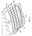
- Fig. 2 shows in diagrammatic form the keypad of Fig. 1 mounted on a substrate or carrier component in a communication device;
- Fig. 3 shows in diagrammatic form a bottom view of a keypad actuator according to an embodiment
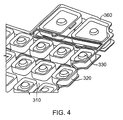
- Fig. 4 is a more detailed view of a portion of the keypad actuator depicted in Fig. 3 ;
- Fig. 5 is a bottom view of the keypad of Fig. 1 ;
- Fig. 6 is a more detailed view of a portion of the keypad of Fig. 5 ;
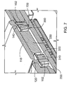
- Fig. 7 is a partial cross-sectional view of the keypad taken along line 1-1 of Fig. 1 ;
- Fig. 8 is a bottom view of the keypad of Fig. 5 with a dome overlay in place.
- Fig. 1 shows in diagrammatic form a keypad assembly according to an embodiment and indicated generally by reference 100.
- Fig. 2 shows the keypad assembly 100 installed, fitted or otherwise mounted or affixed to a printed circuit board (PCB) or other substrate, carrier or structural member for a communication device (e.g. a mobile or handheld), indicated generally by reference 200.
- the PCB 200 is configured with key-switches or contacts for the keypad and other electronic components in known manner.
- the keypad 100 comprises, according to an embodiment, a base-frame or member 102, a plurality of keys indicated by 110, a menu key 112, an ESC key 114, a phone call key 116 and an end phone call key 118.
- the base-frame or member 102 comprises a structural component which may be formed as a plastic frame (e.g. rigid or semi-rigid), and the keys or groups of keys are operatively coupled to the base frame 102.
- the keys are configured as a QWERTY type keypad.
- the keypad 100 may include one or more decoration bars or "frets" 120, indicated individually by references 120a, 120b, 120c and 120d.
- the frets 120 may be formed as part of the base-frame 102 or attached as separate components.
- the keypad assembly may include a socket for a "trackball" (indicated by reference 210 in Fig. 2 ) or other pointer moving mechanism, indicated generally by reference 130.
- the keypad 100 i.e. the base-frame 102
- the edge structure 140 is configured to function in a light guide.
- Figs. 3 and 4 shows a keypad actuator component or insert according to an embodiment and indicated generally by reference 300 in Fig. 3 .
- the keypad actuator or insert 300 is formed from or comprises multiple materials.
- the keypad actuator 300 comprises a light-guide indicated by reference 310, deflection webs 320 and actuators 330.
- the light-guide 310 is formed from a clear or semi-clear plastic material (rigid or semi-rigid) that is co-molded with a corresponding deflection web 320 and actuator 330 for each of the keys.
- the actuators 330 are formed from a resilient material such as silicone material.
- the deflection webs 320 have enough inherent stiffness to hold the keys in their correct position when not pressed, and to yield enough when a user exerts a downward force on the key to bring the associated actuator 330 in contact with the corresponding key-switch component on the PCB 200 ( Fig. 2 ).
- the actuators 330 are formed from a flexible material such as silicone rubber, for example, to provide deflection for tactile feedback to a user.
- each of the actuators 330 comprises a contact dome structure that is configured to function with a dome overlay component, for example, as indicated by reference 800 in Fig. 8 .
- the dome overlay component 800 provides the interface between the keypad 100 and the PCB 200.
- the dome overlay component 800 includes key-switches indicated by reference 810 for each of the actuators 330 ( Fig. 3 ).
- the key-switches 810 are configured to generate a keypad signal on the PCB 200 in response to the depression of the associated actuator 330 and key 110 ( Fig. 1 ) on the keypad 100.
- the dome overlay 800 also includes openings or cut-outs for LEDs configured to provide a backlighting source.
- the keypad actuator or insert 300 includes a sealing structure indicated by reference 360.
- the sealing structure 360 comprises a continuous bead, protrusion or raised ridge which runs around the perimeter of the keypad actuator 300 as depicted in Fig. 3 .
- the sealing structure 360 is formed from a resilient or a compressible material, such as silicone rubber.
- the silicon rubber for the sealing structure or ridge 360 is co-molded in the keypad actuator or insert 300, which comprises the light-guide 310, the deflection webs 320 and the actuators 330.
- the sealing structure 360 is formed from silicone rubber with a height in the range of 0.05 to 0.15 mm and a width in the range of 0.3 to 3.0 mm, although it will be appreciated that other dimensions may be utilized to suit the application.
- the height of the sealing structure 360 is taken as the height above the edge of the keypad, i.e. the surface of the edge structure 140, for example, as depicted in Fig. 7 .
- the keypad actuator 300 includes backlight pockets or sockets indicated by reference 350.
- the backlight pockets 350 receive a light source 352 (e.g. a light emitting diode or LED).
- the LEDs 352 are mounted on and powered from the PCB 200 ( Fig. 2 ).
- the keys in the keypad 100 comprise transparent or semi-transparent keycaps that permit passage of light from the light sources 352 to provide a lighted keypad. To prevent light from the backlighting sources (i.e.
- the base-frame 102 includes the edge structure 140 which serves to provide a backlight shielding function.
- the edge structure 140 comprises a dark (e.g. black) plastic edge that runs substantially around the perimeter of the keypad 100 or base-frame 102 and functions to block the transmission of light emitted by the light source(s) for backlighting the keypad.
- the edge structure 140 also serves to define a cavity or compartment which can assist in the positioning and/or insertion of the keypad actuator layer 300.
- the sealing structure 360 rests on the surface of the PCB 200.
- a sealing structure 360 formed from silicone rubber allows the seal 360 to be compressed against the surface of the PCB 200, which serves to improve the sealing properties.
- the keypad 100 includes a space (i.e. a channel or gap) indicated by reference 700.
- the space or gap 700 runs along the sealing structure 360 and is formed between the edge 140 and the dome overlay.
- the gap 700 provides a space to allow the sealing structure to be compressed when the keypad is assembled, i.e. a force applied during the keypad assembly procedure.
- the gap 700 has a height in the range of 0.05 to 0.10 mm. although it will be appreciated that other dimensions may be appropriate.
- the sealing structure 360 when compressed against the surface of the PCB 200, for example, as depicted in Fig. 7 , provides a seal or barrier to prevent the entry of moisture and/or dust and/or electrostatic discharge into the keypad 100.
- the keypad actuator 300 is formed from multiple materials using a co-molding process.
- the deflection webs 320, the actuators 330 and the sealing bead or protrusion 360 are formed from a first resilient or a compressible material such as silicone rubber, and the light guide 310 is formed from a second material such as a rigid or semi-rigid plastic material. According to an embodiment, this allows the sealing bead or protrusion to be formed at the same time as the actuators 330 and an integral element of the keypad actuator 300.
- the keypad 100 may be installed or implemented with a mobile communication device.
- the mobile communication device comprises electronic circuitry and components configured and/or assembled on the PCB 200.
- the electronic circuitry includes a central processing unit or CPU, which operates under the control of a program (i.e. firmware or software) stored in program memory.
- the CPU is also provided with data memory.
- the CPU is operatively coupled to the keypad 100 and the trackball 210 ( Fig. 2 ), i.e. input devices, a display module and an audio transducer or speaker.
- the program memory may include other applications, such as a browser program.
- the mobile communication device also includes circuitry for wireless communication with a wireless network. The particular implementation details of the mobile communication device will be within the understanding of those skilled in the art, and are therefore not described in further detail.
Landscapes
- Push-Button Switches (AREA)
- Input From Keyboards Or The Like (AREA)
- Telephone Set Structure (AREA)
- Switches With Compound Operations (AREA)
- Cleaning Implements For Floors, Carpets, Furniture, Walls, And The Like (AREA)
Abstract
Description
- The present application relates generally to keypads, and more particularly, to a keypad intended for portable or handheld communication devices.
- The portability and convenience of mobile or handheld communication devices has resulted in their widespread use and popularity. The portability of handheld communication devices also makes them more susceptible to exposure to outdoor elements and hazards, such as moisture (e.g. rain, sleet, and snow), dust, and other environmental elements.
-
EP 1737010 A discloses a push-button switch cover member having a hard base and a keypad formed of a silicone rubber film covering the entire back surface of the hard base. -
EP 1619703 A discloses a key sheet having a base sheet formed by a hard resin base plate and a holding/receiving portion formed of a rubber like elastic material extending around the periphery of the base plate. -
EP 1467391 A discloses a key pad comprising a key sheet formed by a hard resin plate having a reinforcing outer frame formed of a thermoplastic elastomer extending around the periphery of the hard resin plate. - Accordingly, there remains a need for improvements in the art for keypads.
- The present application is directed generally to a keypad and structure that may provide protection against elements such as water, dust and/or electrostatic discharge.
- Embodiments according to the present application are generally directed to a keypad assembly and structure configured to preferably provide a seal against environmental elements or agents, such as water/moisture, dust and/or ESD (Electro-Static Discharge).
- According to an embodiment, there may be provided an actuator component for a keypad, said actuator component comprising: a plurality of actuators formed from a first material; a light guide comprising a plastic material co-molded with said plurality of actuators; and a sealing bead being formed from said silicone rubber and co-molded with said plastic light guide and said raised sealing bead being configured for compression in a channel configured in the keypad.
- Preferably, said sealing bead has a height dimension in the range of 0.05 to 0.15 mm.
- According to another embodiment, there may be provided a process for manufacturing a keypad insert for a keypad, said process comprising: providing a plurality of actuators formed from silicone rubber; providing a light guide formed from a plastic material; providing a raised sealing bead formed from silicone rubber and configured for compression in a gap configured in the keypad; bonding together said plurality of actuators, said light guide and said sealing bead using co-molding.
- Preferably, said sealing bead extends around a perimeter line of the keypad insert.
- According to another embodiment, there may be provided a keypad suitable for use with a mobile communication device and the mobile communication device comprising a mounting substrate, the keypad comprising: a base-frame; a plurality of keys operatively coupled to the base-frame; an actuator component positioned with the base-frame, and the actuator component includes an actuator for each of the keys, and each of the actuators are responsive to depression of an associated one of the keys; and the actuator component comprises a sealing bead running along a perimeter portion of the actuator component formed with the actuator component from a flexible material. The sealing bead may be compressed against the mounting substrate during installation to provide a seal or barrier against environmental agents.
- According to another embodiment, there may be provided an actuator component for a keypad, the actuator component comprising: a plurality of actuators and each of the actuators being formed from a first material; a light guide comprising a plastic material co-molded with the plurality of actuators; and a sealing bead formed from the first material, and co-molded with the light guide.
- According to another embodiment, there may be provided a process for manufacturing a keypad insert, the process comprising: providing a plurality of actuators formed of a first material; providing a light guide formed of a second material; providing a sealing bead formed from the first material; bonding together the plurality of actuators, the light guide and the sealing bead using co-molding.
- According to another embodiment, there may be provided a keypad for a mobile communication device, said mobile communication device having a mounting substrate, said keypad comprising: a base-frame; a plurality of keys operatively coupled to said base-frame; an actuator component positioned with said base-frame, and said actuator component having an actuator for each of said plurality of keys, and each of said actuators being responsive to depression of an associated one of said keys; and said actuator component having a sealing bead running along a perimeter portion of said actuator component formed of a compressible material, and said sealing bead being compressed against the mounting substrate during installation to provide a seal against environmental agents.
- Preferably, said sealing bead comprises a silicone rubber material co-molded with said actuator component.
- Preferably, said actuator component comprises a plastic light guide co-molded with said silicone rubber material for said sealing bead.
- Preferably, said base-frame comprises a perimeter edge defining a gap for allowing compression of said sealing bead when a force is applied during assembly of the keypad.
- Preferably, said actuator component is formed from two or more materials, and said sealing bead is formed from one of said materials.
- According to another embodiment, there may be provided an actuator component for a keypad, said actuator component comprising: a plurality of actuators formed from a first material; a light guide comprising a plastic material co-molded with said plurality of actuators; and a sealing bead being formed from said first material and co-molded with said plastic light guide.
- Preferably, said first material comprises silicone rubber and said sealing bead is formed of silicone rubber.
- Preferably, said sealing bead has a height dimension in the range of 0.05 to 0.15 mm.
- According to another embodiment, there may be provided a process for manufacturing a keypad insert, said process comprising: providing a plurality of actuators formed of a first material; providing a light guide formed of a second material; providing a sealing bead formed from said first material; bonding together said plurality of actuators, said light guide and said sealing bead using co-molding.
- Preferably, said sealing bead is formed from silicone rubber.
- Preferably, said light guide is formed from a plastic material. Preferably, said sealing bead extends around a perimeter line of the keypad insert.
- According to another embodiment, there may be provided a mobile communication device having a keypad according to a previous embodiment, said mobile communication device comprising a display module and an electronic circuit responsive to said keypad and being configured for operating said display module and another electronic circuit configured for wireless communication.
- Other aspects and features will become apparent to those ordinarily skilled in the art upon review of the following description of embodiments in conjunction with the accompanying figures.
- Reference will now be made to the accompanying drawings which show, by way of example, embodiments of the apparatus described herein, and how they may be carried into effect, and in which:
-
Fig. 1 shows in diagrammatic form a keypad according to an embodiment; -
Fig. 2 shows in diagrammatic form the keypad ofFig. 1 mounted on a substrate or carrier component in a communication device; -
Fig. 3 shows in diagrammatic form a bottom view of a keypad actuator according to an embodiment; -
Fig. 4 is a more detailed view of a portion of the keypad actuator depicted inFig. 3 ; -
Fig. 5 is a bottom view of the keypad ofFig. 1 ; -
Fig. 6 is a more detailed view of a portion of the keypad ofFig. 5 ; -
Fig. 7 is a partial cross-sectional view of the keypad taken along line 1-1 ofFig. 1 ; and -
Fig. 8 is a bottom view of the keypad ofFig. 5 with a dome overlay in place. - Like reference numerals indicate like or corresponding elements in the drawings.
- Reference is made to
Fig. 1 , which shows in diagrammatic form a keypad assembly according to an embodiment and indicated generally byreference 100.Fig. 2 shows thekeypad assembly 100 installed, fitted or otherwise mounted or affixed to a printed circuit board (PCB) or other substrate, carrier or structural member for a communication device (e.g. a mobile or handheld), indicated generally byreference 200. The PCB 200 is configured with key-switches or contacts for the keypad and other electronic components in known manner. - In the figures, like reference numerals indicate like or corresponding elements.
- As shown in
Fig. 1 , thekeypad 100 comprises, according to an embodiment, a base-frame ormember 102, a plurality of keys indicated by 110, amenu key 112, anESC key 114, aphone call key 116 and an endphone call key 118. The base-frame ormember 102 comprises a structural component which may be formed as a plastic frame (e.g. rigid or semi-rigid), and the keys or groups of keys are operatively coupled to thebase frame 102. According to an embodiment the keys are configured as a QWERTY type keypad. As also shown, thekeypad 100 may include one or more decoration bars or "frets" 120, indicated individually byreferences frets 120 may be formed as part of the base-frame 102 or attached as separate components. According to another aspect, the keypad assembly may include a socket for a "trackball" (indicated byreference 210 inFig. 2 ) or other pointer moving mechanism, indicated generally byreference 130. The keypad 100 (i.e. the base-frame 102) includes an edge structure indicated by reference 140 (Fig. 2 ). According to an embodiment, theedge structure 140 is configured to function in a light guide. - Reference is next made to
Figs. 3 and4 , which shows a keypad actuator component or insert according to an embodiment and indicated generally byreference 300 inFig. 3 . The keypad actuator orinsert 300 is formed from or comprises multiple materials. According to an embodiment, thekeypad actuator 300 comprises a light-guide indicated byreference 310,deflection webs 320 andactuators 330. According to an embodiment, the light-guide 310 is formed from a clear or semi-clear plastic material (rigid or semi-rigid) that is co-molded with acorresponding deflection web 320 andactuator 330 for each of the keys. According to an embodiment, theactuators 330 are formed from a resilient material such as silicone material. Thedeflection webs 320 have enough inherent stiffness to hold the keys in their correct position when not pressed, and to yield enough when a user exerts a downward force on the key to bring theassociated actuator 330 in contact with the corresponding key-switch component on the PCB 200 (Fig. 2 ). - According to an embodiment, the
actuators 330 are formed from a flexible material such as silicone rubber, for example, to provide deflection for tactile feedback to a user. According to an embodiment, each of theactuators 330 comprises a contact dome structure that is configured to function with a dome overlay component, for example, as indicated byreference 800 inFig. 8 . Thedome overlay component 800 provides the interface between thekeypad 100 and the PCB 200. Thedome overlay component 800 includes key-switches indicated byreference 810 for each of the actuators 330 (Fig. 3 ). The key-switches 810 are configured to generate a keypad signal on thePCB 200 in response to the depression of the associatedactuator 330 and key 110 (Fig. 1 ) on thekeypad 100. Thedome overlay 800 also includes openings or cut-outs for LEDs configured to provide a backlighting source. - Referring back to
Figs. 3 and4 , the keypad actuator or insert 300 includes a sealing structure indicated byreference 360. According to an embodiment, the sealingstructure 360 comprises a continuous bead, protrusion or raised ridge which runs around the perimeter of thekeypad actuator 300 as depicted inFig. 3 . According to an embodiment, the sealingstructure 360 is formed from a resilient or a compressible material, such as silicone rubber. According to an embodiment, the silicon rubber for the sealing structure orridge 360 is co-molded in the keypad actuator or insert 300, which comprises the light-guide 310, thedeflection webs 320 and theactuators 330. In an implementation, the sealingstructure 360 is formed from silicone rubber with a height in the range of 0.05 to 0.15 mm and a width in the range of 0.3 to 3.0 mm, although it will be appreciated that other dimensions may be utilized to suit the application. The height of the sealingstructure 360 is taken as the height above the edge of the keypad, i.e. the surface of theedge structure 140, for example, as depicted inFig. 7 . - Reference is next made to
Figs. 5 and6 , which show a bottom view of thekeypad 100 with the keypad actuator or insert 300 in place. As shown, thekeypad actuator 300 includes backlight pockets or sockets indicated byreference 350. The backlight pockets 350 receive a light source 352 (e.g. a light emitting diode or LED). TheLEDs 352 are mounted on and powered from the PCB 200 (Fig. 2 ). According to an embodiment, the keys in thekeypad 100 comprise transparent or semi-transparent keycaps that permit passage of light from thelight sources 352 to provide a lighted keypad. To prevent light from the backlighting sources (i.e. the LEDs) from leaking outside the edges or periphery of the keypad, the base-frame 102 includes theedge structure 140 which serves to provide a backlight shielding function. According to an embodiment, theedge structure 140 comprises a dark (e.g. black) plastic edge that runs substantially around the perimeter of thekeypad 100 or base-frame 102 and functions to block the transmission of light emitted by the light source(s) for backlighting the keypad. Theedge structure 140 also serves to define a cavity or compartment which can assist in the positioning and/or insertion of thekeypad actuator layer 300. - Reference is next made to
Fig. 7 , which shows the configuration of the sealingstructure 360 in more detail. As shown inFig. 7 , the sealingstructure 360 rests on the surface of thePCB 200. A sealingstructure 360 formed from silicone rubber allows theseal 360 to be compressed against the surface of thePCB 200, which serves to improve the sealing properties. According to an embodiment, thekeypad 100 includes a space (i.e. a channel or gap) indicated byreference 700. The space orgap 700 runs along the sealingstructure 360 and is formed between theedge 140 and the dome overlay. Thegap 700 provides a space to allow the sealing structure to be compressed when the keypad is assembled, i.e. a force applied during the keypad assembly procedure. According to an embodiment, thegap 700 has a height in the range of 0.05 to 0.10 mm. although it will be appreciated that other dimensions may be appropriate. - According to an aspect, the sealing
structure 360 when compressed against the surface of thePCB 200, for example, as depicted inFig. 7 , provides a seal or barrier to prevent the entry of moisture and/or dust and/or electrostatic discharge into thekeypad 100. - In accordance with an embodiment, the
keypad actuator 300 is formed from multiple materials using a co-molding process. For example, thedeflection webs 320, theactuators 330 and the sealing bead orprotrusion 360 are formed from a first resilient or a compressible material such as silicone rubber, and thelight guide 310 is formed from a second material such as a rigid or semi-rigid plastic material. According to an embodiment, this allows the sealing bead or protrusion to be formed at the same time as theactuators 330 and an integral element of thekeypad actuator 300. - The
keypad 100 may be installed or implemented with a mobile communication device. The mobile communication device comprises electronic circuitry and components configured and/or assembled on thePCB 200. The electronic circuitry includes a central processing unit or CPU, which operates under the control of a program (i.e. firmware or software) stored in program memory. The CPU is also provided with data memory. The CPU is operatively coupled to thekeypad 100 and the trackball 210 (Fig. 2 ), i.e. input devices, a display module and an audio transducer or speaker. In addition to the program executable code provided for performing the functions associated with the operation of the mobile communication device, the program memory may include other applications, such as a browser program. The mobile communication device also includes circuitry for wireless communication with a wireless network. The particular implementation details of the mobile communication device will be within the understanding of those skilled in the art, and are therefore not described in further detail. - While the embodiments according to the present application have been described in the context of mobile communication devices, the embodiments may be extended or find application in other types devices having a keypad or keys.
- The keypad according to the present application may be embodied in other specific forms without departing from the spirit or essential characteristics thereof. Certain adaptations and modifications of the keypad will be obvious to those skilled in the art. Therefore, the presently discussed embodiments are considered to be illustrative and not restrictive, and the scope being indicated by the appended claims rather than the foregoing description, and all changes which come within the meaning and range of equivalency of the claims are therefore intended to be embraced therein.
Claims (4)
- An actuator component (300) for a keypad (100), said actuator component (300) comprising:a plurality of actuators (330) formed from a first material;a light guide (310) comprising a plastic material co-molded with said plurality of actuators (330); anda sealing bead (360) being formed from said silicone rubber and co-molded with said plastic light guide (310) and said raised sealing bead (360) being configured for compression in a channel configured in the keypad.
- The actuator component as claimed in claim 1, wherein said sealing bead has a height dimension in the range of 0.05 to 0.15 mm.
- A process for manufacturing a keypad insert (300) for a keypad, said process comprising:providing a plurality of actuators (330) formed from silicone rubber;providing a light guide (310) formed from a plastic material;providing a raised sealing bead (360) formed from silicone rubber and configured for compression in a gap configured in the keypad;bonding together said plurality of actuators (330), said light guide (310) and said sealing bead (360) using co-molding.
- The process as claimed in claim 3, wherein said sealing bead extends around a perimeter line of the keypad insert.
Applications Claiming Priority (1)
| Application Number | Priority Date | Filing Date | Title |
|---|---|---|---|
| EP08152961A EP2104126B1 (en) | 2008-03-18 | 2008-03-18 | Keypad with water and dust protection |
Related Parent Applications (1)
| Application Number | Title | Priority Date | Filing Date |
|---|---|---|---|
| EP08152961.2 Division | 2008-03-18 |
Publications (2)
| Publication Number | Publication Date |
|---|---|
| EP2270824A1 true EP2270824A1 (en) | 2011-01-05 |
| EP2270824B1 EP2270824B1 (en) | 2011-11-09 |
Family
ID=39339819
Family Applications (2)
| Application Number | Title | Priority Date | Filing Date |
|---|---|---|---|
| EP08152961A Active EP2104126B1 (en) | 2008-03-18 | 2008-03-18 | Keypad with water and dust protection |
| EP10188124A Active EP2270824B1 (en) | 2008-03-18 | 2008-03-18 | Keypad with Water and Dust Protection |
Family Applications Before (1)
| Application Number | Title | Priority Date | Filing Date |
|---|---|---|---|
| EP08152961A Active EP2104126B1 (en) | 2008-03-18 | 2008-03-18 | Keypad with water and dust protection |
Country Status (5)
| Country | Link |
|---|---|
| EP (2) | EP2104126B1 (en) |
| CN (1) | CN201893261U (en) |
| AT (2) | ATE533167T1 (en) |
| CA (1) | CA2657735C (en) |
| DE (1) | DE602008004090D1 (en) |
Families Citing this family (3)
| Publication number | Priority date | Publication date | Assignee | Title |
|---|---|---|---|---|
| US9075576B2 (en) | 2010-02-25 | 2015-07-07 | Blackberry Limited | Keypads for mobile devices and method of manufacturing the same |
| EP2362405B1 (en) * | 2010-02-25 | 2016-05-04 | BlackBerry Limited | Keypads for mobile devices and method of manufacturing the same |
| CN205725872U (en) * | 2016-03-17 | 2016-11-23 | 中兴通讯股份有限公司 | A kind of button and terminal |
Citations (4)
| Publication number | Priority date | Publication date | Assignee | Title |
|---|---|---|---|---|
| EP1467391A1 (en) | 2003-04-11 | 2004-10-13 | Polymatech Co., Ltd. | Key sheets and method of producing the same |
| EP1619703A2 (en) | 2004-07-20 | 2006-01-25 | Polymatech Co., Ltd. | Key sheet and key sheet manufacturing method |
| EP1737010A1 (en) | 2004-03-25 | 2006-12-27 | Shin-Etsu Polymer Co., Ltd. | Cover member for push-button switch and method of manufacturing the same |
| WO2008018416A1 (en) * | 2006-08-07 | 2008-02-14 | Sunarrow Limited | Key sheet, key unit having it, and key sheet manufacturing method |
Family Cites Families (1)
| Publication number | Priority date | Publication date | Assignee | Title |
|---|---|---|---|---|
| JP2000151772A (en) * | 1998-11-12 | 2000-05-30 | Matsushita Electric Ind Co Ltd | Mobile terminal device |
-
2008
- 2008-03-18 DE DE602008004090T patent/DE602008004090D1/en active Active
- 2008-03-18 EP EP08152961A patent/EP2104126B1/en active Active
- 2008-03-18 EP EP10188124A patent/EP2270824B1/en active Active
- 2008-03-18 AT AT10188124T patent/ATE533167T1/en active
- 2008-03-18 AT AT08152961T patent/ATE492898T1/en not_active IP Right Cessation
-
2009
- 2009-03-10 CA CA2657735A patent/CA2657735C/en active Active
- 2009-03-18 CN CN2009200087368U patent/CN201893261U/en not_active Expired - Lifetime
Patent Citations (4)
| Publication number | Priority date | Publication date | Assignee | Title |
|---|---|---|---|---|
| EP1467391A1 (en) | 2003-04-11 | 2004-10-13 | Polymatech Co., Ltd. | Key sheets and method of producing the same |
| EP1737010A1 (en) | 2004-03-25 | 2006-12-27 | Shin-Etsu Polymer Co., Ltd. | Cover member for push-button switch and method of manufacturing the same |
| EP1619703A2 (en) | 2004-07-20 | 2006-01-25 | Polymatech Co., Ltd. | Key sheet and key sheet manufacturing method |
| WO2008018416A1 (en) * | 2006-08-07 | 2008-02-14 | Sunarrow Limited | Key sheet, key unit having it, and key sheet manufacturing method |
Also Published As
| Publication number | Publication date |
|---|---|
| HK1136085A1 (en) | 2010-06-18 |
| EP2270824B1 (en) | 2011-11-09 |
| CA2657735A1 (en) | 2009-09-18 |
| EP2104126A1 (en) | 2009-09-23 |
| DE602008004090D1 (en) | 2011-02-03 |
| CA2657735C (en) | 2013-08-27 |
| CN201893261U (en) | 2011-07-06 |
| ATE492898T1 (en) | 2011-01-15 |
| ATE533167T1 (en) | 2011-11-15 |
| EP2104126B1 (en) | 2010-12-22 |
Similar Documents
| Publication | Publication Date | Title |
|---|---|---|
| US8050019B2 (en) | Keypad with water and dust protection | |
| US9450631B2 (en) | Case for a hand held device | |
| EP1901321B1 (en) | Key assembly and mobile terminal having the same | |
| US7345250B2 (en) | Keyboard with key supporting structure for portable electronics devices | |
| US8441445B2 (en) | Electrophoretic display keypad structure | |
| US6861600B1 (en) | Integrated switch and backlight assembly | |
| US8207464B2 (en) | Portable terminal | |
| US8085246B2 (en) | Keypad panel assembly having laterally-illuminated keypad surface | |
| EP2270824B1 (en) | Keypad with Water and Dust Protection | |
| US20100224473A1 (en) | Multi-function switch structure | |
| US7679015B2 (en) | Keypad assembly for electronic device | |
| KR101095547B1 (en) | Dome switch cover member and keypad including the same | |
| JPH06275169A (en) | Keyboard switch | |
| HK1136085B (en) | Keypad with water and dust protection | |
| JP5619369B2 (en) | Seat switch | |
| JP3293077B2 (en) | Flexible illuminated key | |
| CN102136386A (en) | Key component and portable electronic device with key component | |
| WO2008078143A1 (en) | A keypad assembly | |
| KR20130007240A (en) | Mobile terminal | |
| CN101091230A (en) | Thin key sheet and thin key unit incorporating the thin key sheet | |
| JP2008159346A (en) | Portable electronic devices |
Legal Events
| Date | Code | Title | Description |
|---|---|---|---|
| PUAI | Public reference made under article 153(3) epc to a published international application that has entered the european phase |
Free format text: ORIGINAL CODE: 0009012 |
|
| 17P | Request for examination filed |
Effective date: 20101024 |
|
| AC | Divisional application: reference to earlier application |
Ref document number: 2104126 Country of ref document: EP Kind code of ref document: P |
|
| AK | Designated contracting states |
Kind code of ref document: A1 Designated state(s): AT BE BG CH CY CZ DE DK EE ES FI FR GB GR HR HU IE IS IT LI LT LU LV MC MT NL NO PL PT RO SE SI SK TR |
|
| AX | Request for extension of the european patent |
Extension state: AL BA MK RS |
|
| GRAP | Despatch of communication of intention to grant a patent |
Free format text: ORIGINAL CODE: EPIDOSNIGR1 |
|
| RIC1 | Information provided on ipc code assigned before grant |
Ipc: H01H 13/88 20060101ALI20110509BHEP Ipc: H01H 13/702 20060101AFI20110509BHEP Ipc: H01H 13/86 20060101ALI20110509BHEP |
|
| GRAS | Grant fee paid |
Free format text: ORIGINAL CODE: EPIDOSNIGR3 |
|
| GRAA | (expected) grant |
Free format text: ORIGINAL CODE: 0009210 |
|
| AC | Divisional application: reference to earlier application |
Ref document number: 2104126 Country of ref document: EP Kind code of ref document: P |
|
| AK | Designated contracting states |
Kind code of ref document: B1 Designated state(s): AT BE BG CH CY CZ DE DK EE ES FI FR GB GR HR HU IE IS IT LI LT LU LV MC MT NL NO PL PT RO SE SI SK TR |
|
| REG | Reference to a national code |
Ref country code: GB Ref legal event code: FG4D |
|
| REG | Reference to a national code |
Ref country code: CH Ref legal event code: EP |
|
| REG | Reference to a national code |
Ref country code: IE Ref legal event code: FG4D |
|
| REG | Reference to a national code |
Ref country code: DE Ref legal event code: R096 Ref document number: 602008011346 Country of ref document: DE Effective date: 20120209 |
|
| REG | Reference to a national code |
Ref country code: NL Ref legal event code: VDEP Effective date: 20111109 |
|
| LTIE | Lt: invalidation of european patent or patent extension |
Effective date: 20111109 |
|
| PG25 | Lapsed in a contracting state [announced via postgrant information from national office to epo] |
Ref country code: IS Free format text: LAPSE BECAUSE OF FAILURE TO SUBMIT A TRANSLATION OF THE DESCRIPTION OR TO PAY THE FEE WITHIN THE PRESCRIBED TIME-LIMIT Effective date: 20120309 Ref country code: NO Free format text: LAPSE BECAUSE OF FAILURE TO SUBMIT A TRANSLATION OF THE DESCRIPTION OR TO PAY THE FEE WITHIN THE PRESCRIBED TIME-LIMIT Effective date: 20120209 Ref country code: LT Free format text: LAPSE BECAUSE OF FAILURE TO SUBMIT A TRANSLATION OF THE DESCRIPTION OR TO PAY THE FEE WITHIN THE PRESCRIBED TIME-LIMIT Effective date: 20111109 |
|
| PG25 | Lapsed in a contracting state [announced via postgrant information from national office to epo] |
Ref country code: PL Free format text: LAPSE BECAUSE OF FAILURE TO SUBMIT A TRANSLATION OF THE DESCRIPTION OR TO PAY THE FEE WITHIN THE PRESCRIBED TIME-LIMIT Effective date: 20111109 Ref country code: NL Free format text: LAPSE BECAUSE OF FAILURE TO SUBMIT A TRANSLATION OF THE DESCRIPTION OR TO PAY THE FEE WITHIN THE PRESCRIBED TIME-LIMIT Effective date: 20111109 Ref country code: HR Free format text: LAPSE BECAUSE OF FAILURE TO SUBMIT A TRANSLATION OF THE DESCRIPTION OR TO PAY THE FEE WITHIN THE PRESCRIBED TIME-LIMIT Effective date: 20111109 Ref country code: PT Free format text: LAPSE BECAUSE OF FAILURE TO SUBMIT A TRANSLATION OF THE DESCRIPTION OR TO PAY THE FEE WITHIN THE PRESCRIBED TIME-LIMIT Effective date: 20120309 Ref country code: GR Free format text: LAPSE BECAUSE OF FAILURE TO SUBMIT A TRANSLATION OF THE DESCRIPTION OR TO PAY THE FEE WITHIN THE PRESCRIBED TIME-LIMIT Effective date: 20120210 Ref country code: SE Free format text: LAPSE BECAUSE OF FAILURE TO SUBMIT A TRANSLATION OF THE DESCRIPTION OR TO PAY THE FEE WITHIN THE PRESCRIBED TIME-LIMIT Effective date: 20111109 Ref country code: SI Free format text: LAPSE BECAUSE OF FAILURE TO SUBMIT A TRANSLATION OF THE DESCRIPTION OR TO PAY THE FEE WITHIN THE PRESCRIBED TIME-LIMIT Effective date: 20111109 Ref country code: BE Free format text: LAPSE BECAUSE OF FAILURE TO SUBMIT A TRANSLATION OF THE DESCRIPTION OR TO PAY THE FEE WITHIN THE PRESCRIBED TIME-LIMIT Effective date: 20111109 Ref country code: LV Free format text: LAPSE BECAUSE OF FAILURE TO SUBMIT A TRANSLATION OF THE DESCRIPTION OR TO PAY THE FEE WITHIN THE PRESCRIBED TIME-LIMIT Effective date: 20111109 |
|
| PG25 | Lapsed in a contracting state [announced via postgrant information from national office to epo] |
Ref country code: CY Free format text: LAPSE BECAUSE OF FAILURE TO SUBMIT A TRANSLATION OF THE DESCRIPTION OR TO PAY THE FEE WITHIN THE PRESCRIBED TIME-LIMIT Effective date: 20111109 |
|
| PG25 | Lapsed in a contracting state [announced via postgrant information from national office to epo] |
Ref country code: DK Free format text: LAPSE BECAUSE OF FAILURE TO SUBMIT A TRANSLATION OF THE DESCRIPTION OR TO PAY THE FEE WITHIN THE PRESCRIBED TIME-LIMIT Effective date: 20111109 Ref country code: BG Free format text: LAPSE BECAUSE OF FAILURE TO SUBMIT A TRANSLATION OF THE DESCRIPTION OR TO PAY THE FEE WITHIN THE PRESCRIBED TIME-LIMIT Effective date: 20120209 Ref country code: SK Free format text: LAPSE BECAUSE OF FAILURE TO SUBMIT A TRANSLATION OF THE DESCRIPTION OR TO PAY THE FEE WITHIN THE PRESCRIBED TIME-LIMIT Effective date: 20111109 Ref country code: EE Free format text: LAPSE BECAUSE OF FAILURE TO SUBMIT A TRANSLATION OF THE DESCRIPTION OR TO PAY THE FEE WITHIN THE PRESCRIBED TIME-LIMIT Effective date: 20111109 Ref country code: CZ Free format text: LAPSE BECAUSE OF FAILURE TO SUBMIT A TRANSLATION OF THE DESCRIPTION OR TO PAY THE FEE WITHIN THE PRESCRIBED TIME-LIMIT Effective date: 20111109 |
|
| PG25 | Lapsed in a contracting state [announced via postgrant information from national office to epo] |
Ref country code: IT Free format text: LAPSE BECAUSE OF FAILURE TO SUBMIT A TRANSLATION OF THE DESCRIPTION OR TO PAY THE FEE WITHIN THE PRESCRIBED TIME-LIMIT Effective date: 20111109 Ref country code: RO Free format text: LAPSE BECAUSE OF FAILURE TO SUBMIT A TRANSLATION OF THE DESCRIPTION OR TO PAY THE FEE WITHIN THE PRESCRIBED TIME-LIMIT Effective date: 20111109 |
|
| PLBE | No opposition filed within time limit |
Free format text: ORIGINAL CODE: 0009261 |
|
| STAA | Information on the status of an ep patent application or granted ep patent |
Free format text: STATUS: NO OPPOSITION FILED WITHIN TIME LIMIT |
|
| REG | Reference to a national code |
Ref country code: AT Ref legal event code: MK05 Ref document number: 533167 Country of ref document: AT Kind code of ref document: T Effective date: 20111109 |
|
| 26N | No opposition filed |
Effective date: 20120810 |
|
| PG25 | Lapsed in a contracting state [announced via postgrant information from national office to epo] |
Ref country code: MC Free format text: LAPSE BECAUSE OF NON-PAYMENT OF DUE FEES Effective date: 20120331 |
|
| REG | Reference to a national code |
Ref country code: CH Ref legal event code: PL |
|
| REG | Reference to a national code |
Ref country code: DE Ref legal event code: R097 Ref document number: 602008011346 Country of ref document: DE Effective date: 20120810 |
|
| REG | Reference to a national code |
Ref country code: IE Ref legal event code: MM4A |
|
| PG25 | Lapsed in a contracting state [announced via postgrant information from national office to epo] |
Ref country code: IE Free format text: LAPSE BECAUSE OF NON-PAYMENT OF DUE FEES Effective date: 20120318 Ref country code: CH Free format text: LAPSE BECAUSE OF NON-PAYMENT OF DUE FEES Effective date: 20120331 Ref country code: LI Free format text: LAPSE BECAUSE OF NON-PAYMENT OF DUE FEES Effective date: 20120331 Ref country code: AT Free format text: LAPSE BECAUSE OF FAILURE TO SUBMIT A TRANSLATION OF THE DESCRIPTION OR TO PAY THE FEE WITHIN THE PRESCRIBED TIME-LIMIT Effective date: 20111109 |
|
| PG25 | Lapsed in a contracting state [announced via postgrant information from national office to epo] |
Ref country code: ES Free format text: LAPSE BECAUSE OF FAILURE TO SUBMIT A TRANSLATION OF THE DESCRIPTION OR TO PAY THE FEE WITHIN THE PRESCRIBED TIME-LIMIT Effective date: 20120220 |
|
| PG25 | Lapsed in a contracting state [announced via postgrant information from national office to epo] |
Ref country code: FI Free format text: LAPSE BECAUSE OF FAILURE TO SUBMIT A TRANSLATION OF THE DESCRIPTION OR TO PAY THE FEE WITHIN THE PRESCRIBED TIME-LIMIT Effective date: 20111109 |
|
| PG25 | Lapsed in a contracting state [announced via postgrant information from national office to epo] |
Ref country code: MT Free format text: LAPSE BECAUSE OF FAILURE TO SUBMIT A TRANSLATION OF THE DESCRIPTION OR TO PAY THE FEE WITHIN THE PRESCRIBED TIME-LIMIT Effective date: 20111109 |
|
| PG25 | Lapsed in a contracting state [announced via postgrant information from national office to epo] |
Ref country code: TR Free format text: LAPSE BECAUSE OF FAILURE TO SUBMIT A TRANSLATION OF THE DESCRIPTION OR TO PAY THE FEE WITHIN THE PRESCRIBED TIME-LIMIT Effective date: 20111109 |
|
| PG25 | Lapsed in a contracting state [announced via postgrant information from national office to epo] |
Ref country code: LU Free format text: LAPSE BECAUSE OF NON-PAYMENT OF DUE FEES Effective date: 20120318 |
|
| PG25 | Lapsed in a contracting state [announced via postgrant information from national office to epo] |
Ref country code: HU Free format text: LAPSE BECAUSE OF FAILURE TO SUBMIT A TRANSLATION OF THE DESCRIPTION OR TO PAY THE FEE WITHIN THE PRESCRIBED TIME-LIMIT Effective date: 20080318 |
|
| REG | Reference to a national code |
Ref country code: DE Ref legal event code: R082 Ref document number: 602008011346 Country of ref document: DE Representative=s name: MERH-IP MATIAS ERNY REICHL HOFFMANN, DE |
|
| REG | Reference to a national code |
Ref country code: DE Ref legal event code: R081 Ref document number: 602008011346 Country of ref document: DE Owner name: BLACKBERRY LIMITED, WATERLOO, CA Free format text: FORMER OWNER: RESEARCH IN MOTION LIMITED, WATERLOO, ONTARIO, CA Effective date: 20140926 Ref country code: DE Ref legal event code: R082 Ref document number: 602008011346 Country of ref document: DE Representative=s name: MERH-IP MATIAS ERNY REICHL HOFFMANN, DE Effective date: 20140926 Ref country code: DE Ref legal event code: R082 Ref document number: 602008011346 Country of ref document: DE Representative=s name: MERH-IP MATIAS ERNY REICHL HOFFMANN PATENTANWA, DE Effective date: 20140926 |
|
| REG | Reference to a national code |
Ref country code: FR Ref legal event code: PLFP Year of fee payment: 9 |
|
| REG | Reference to a national code |
Ref country code: FR Ref legal event code: PLFP Year of fee payment: 10 |
|
| REG | Reference to a national code |
Ref country code: FR Ref legal event code: PLFP Year of fee payment: 11 |
|
| REG | Reference to a national code |
Ref country code: DE Ref legal event code: R082 Ref document number: 602008011346 Country of ref document: DE Ref country code: DE Ref legal event code: R081 Ref document number: 602008011346 Country of ref document: DE Owner name: MALIKIE INNOVATIONS LTD., IE Free format text: FORMER OWNER: BLACKBERRY LIMITED, WATERLOO, ONTARIO, CA |
|
| PGFP | Annual fee paid to national office [announced via postgrant information from national office to epo] |
Ref country code: DE Payment date: 20250327 Year of fee payment: 18 |
|
| PGFP | Annual fee paid to national office [announced via postgrant information from national office to epo] |
Ref country code: FR Payment date: 20250324 Year of fee payment: 18 |
|
| PGFP | Annual fee paid to national office [announced via postgrant information from national office to epo] |
Ref country code: GB Payment date: 20250325 Year of fee payment: 18 |