EP2270753A1 - System and method for intermediate mipmap level generation - Google Patents
System and method for intermediate mipmap level generation Download PDFInfo
- Publication number
- EP2270753A1 EP2270753A1 EP20100004960 EP10004960A EP2270753A1 EP 2270753 A1 EP2270753 A1 EP 2270753A1 EP 20100004960 EP20100004960 EP 20100004960 EP 10004960 A EP10004960 A EP 10004960A EP 2270753 A1 EP2270753 A1 EP 2270753A1
- Authority
- EP
- European Patent Office
- Prior art keywords
- mipmap
- interpolation
- kernel
- filter kernel
- filter
- Prior art date
- Legal status (The legal status is an assumption and is not a legal conclusion. Google has not performed a legal analysis and makes no representation as to the accuracy of the status listed.)
- Withdrawn
Links
Images


Classifications
-
- G—PHYSICS
- G06—COMPUTING OR CALCULATING; COUNTING
- G06T—IMAGE DATA PROCESSING OR GENERATION, IN GENERAL
- G06T15/00—Three-dimensional [3D] image rendering
- G06T15/04—Texture mapping
Definitions
- the present invention relates generally to computer generated images. More particularly, the present invention relates to mipmap filtering with increased efficiency and quality.
- Mipmapping is a common technique used to accelerate texture mapping for computer generated three-dimensional rendering applications. Such applications may include rendering for animated films and other media, or real-time rendering for videogames and other simulations.
- a renderer can select a mipmap closely matching a resolution of a projected mapping of the texture instead of always using the original high-resolution texture. In this manner, filtering operations can operate faster on lower resolution mipmaps, shortening rendering time or increasing real-time performance, sometimes by orders-of-magnitude, with very little quality degradation.
- One difficulty arising from the use of mipmaps is visual artifacting that results from the renderer filtering between mipmap transitions in a rendered scene. For example, a tiled texture on a floor or wall in perspective may appear to have abrupt changes in resolution as the renderer switches from one mipmap level to another.
- One way this is commonly addressed is by using trilinear interpolation or other interpolation methods that read texels from two mipmap levels, smoothly blending between the two.
- reading the texels of multiple mipmap levels may place a large I/O burden on the renderer, particularly for high-resolution textures having many mipmaps, reducing rendering efficiency.
- the present application is directed to a system and method for filter kernel interpolation for seamless mipmap filtering.
- the following description contains specific information pertaining to the implementation of the present invention.
- One skilled in the art will recognize that the present invention may be implemented in a manner different from that specifically discussed in the present application. Moreover, some of the specific details of the invention are not discussed in order not to obscure the invention. The specific details not described in the present application are within the knowledge of a person of ordinary skill in the art.
- the drawings in the present application and their accompanying detailed description are directed to merely exemplary embodiments of the invention. To maintain brevity, other embodiments of the invention, which use the principles of the present invention, are not specifically described in the present application and are not specifically illustrated by the present drawings.
- Figure 1 presents a rendering device using filter kernel interpolation for seamless mipmap filtering, according to one embodiment of the present invention.
- Environment 100 of Figure 1 includes rendering device 100 and display 160.
- Rendering device 100 includes processor 111, memory 112, rendering program 115, interpolation 135, interpolated kernel weights 140, filter kernel 145, filtered texture 150, and rendered scene 155.
- Memory 112 includes base-image texture 120, prefilter 125, and mipmap set 130.
- Mipmap set 130 includes mipmaps 131a-131e.
- FIG. 1 presents an overview of an exemplary rendering device 110 for generating rendered scene 155.
- memory 112 already stores base-image texture 120, which corresponds to a level 0 mipmap.
- Base-image texture 120 may comprise a one, two, or even three-dimensional texture for mapping onto surfaces, although a two-dimensional texture may be most commonly used for a typical three-dimensional renderer.
- Dimension is being used here in the sense of the domain of the texels, such as X, Y, Z axes, rather than the range of texels, such as for example red-green-blue (RGB) color channels.
- RGB red-green-blue
- Base-image texture 120 comprises a map of surface colors, which might comprise a plurality of texels in a red-green-blue (RGB) or red-green-blue-alpha (RGBA) format.
- Processor 111 may be directed by rendering program 115 to generate mipmap set 130 in advance by applying prefilter 125 to base-image texture 120. If mipmap set 130 comprises a set of symmetric power-of-two reductions, then a simple successive averaging algorithm or box prefilter may be used to generate mipmaps 131b-131e of mipmap set 130, and mipmap 131a may simply copy base-image texture 120 without modification. However, other prefilters such as a tent or gaussian filter may be used as well.
- base-image texture 120 and mipmap 131a may correspond to a 16 texel 1D texture
- mipmap 131b may correspond to an 8 texel 1D texture
- mipmap 131c may correspond to a 4 texel 1D texture
- mipmap 131d may correspond to a 2 texel 1D texture
- mipmap 131e may correspond to a 1 texel 1D texture.
- Alternative embodiments may further include asymmetric ripmaps in addition to standard symmetric mipmaps.
- processor 111 might store only the most commonly anticipated mipmaps within mipmap set 130 and generate the rest on demand.
- a floor texture might include a symmetric mipmap set and an asymmetric ripmap set retaining high resolution along the horizontal axis in anticipation of the renderer tiling the floor texture on a horizontal plane at an oblique angle to the view camera. Since asymmetric ripmaps retaining high resolution along the vertical axis may be accessed very infrequently for a floor texture, these ripmaps might be omitted from mipmap set 130 and instead generated on demand.
- rendering device 110 may typically have access to several different base-image textures and corresponding mipmap sets for reconstructing rendered scene 155. In this manner, rendering device 110 can select from various textures suitable for mapping onto surfaces of three-dimensional models, producing a more realistic and detailed rendered scene 155. However, for simplicity, only a single base-image texture 120 and mipmap set 130 are shown in Figure 1 .
- base-image texture 120 After rendering program 115 decides a surface for base-image texture 120 to be mapped on, base-image texture 120 must be scaled to match the projection of the surface by a particular camera view used by rendering program 115. That is, if the surface is on a distant object relative to the camera view, the texture needs to be scaled down or minified, and if the surface is close to the camera view, the texture needs to be scaled up or magnified, and if the surface is not directly facing the camera view, which is likely to be the case, the renderer will need to transform the texture to match the proper surface orientation relative to the camera view.
- rendering program 115 must determine how to filter the texels as pixels of display 160 may correspond to several texels or fractional texels. This filtering process is necessary since memory 112 only contains base-image texture 120 at specific resolutions contained in mipmap set 130, whereas mapping the texture may require any arbitrary resolution depending on the positioning of a surface to be mapped.
- this filtering process might be accomplished by selecting one or more mipmaps from mipmap set 130 and applying interpolation 135 and filter kernel 145.
- An appropriate mipmap level is chosen based on the minimum resolution necessary to retain rendering quality while simultaneously reducing rendering workload, which generally corresponds to a mipmap level having texels just smaller than a chosen filter width corresponding to a desired rendering resolution. If interpolation between mipmap levels is desired to avoid discontinuities when switching mipmap levels, then a second mipmap level L+1 may also be necessary for interpolation. Furthermore, if anisotropic filtering is desired, then interpolation needs to be considered for each separate axis; for example, a two-dimensional texture requires four mipmap levels to be interpolated.
- interpolated kernel weights 140 are calculated and applied to a surface via filter kernel 145, it may result in filtered texture 150, which can then be incorporated along with other filtered textures into rendered scene 155 as a final result. Then, rendered scene 155 can be output directly to display 160 for viewing, or may be written to storage such as a hard disk drive for future retrieval and output to display 160 or another display. If rendering program 115 is generating an animation rather than a still frame, then a rendered scene 155 will be generated for each animation frame and updated on display 160 or successively written to the storage.
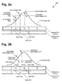
- Figure 2a presents a diagram illustrating filter kernel value interpolation for seamless mipmap filtering, according to one embodiment of the present invention.
- Diagram 200 of Figure 2a includes mipmaps 231a-231b, filter kernel 245, kernel weights 246a-246c, and interpolated kernel weights 247a-247b.
- Mipmap 231a includes texels 232a-232b, and mipmap 231b includes texel 232c.
- mipmap 231a corresponds to mipmap 131a from Figure 1
- mipmap 231b corresponds to mipmap 131b.
- Figure 2a illustrates the technique described as filter kernel value interpolation, which is generally usable for any type of prefilter and filter kernel.
- a function with a result mathematically equivalent to the traditional interpolation technique can be derived by substituting an expected data value from the second mipmap level L+1 on the fly, rather than accessing it from the stored mipmap level L+1.
- the equation above is one method of determining a mipmap level based on a chosen filter width; similar alternative formulations may also be used, such as for example an equation using a ceiling function instead of a floor function, or an equation subtracting a constant value offset from the level value to minimize prefilter aliasing.
- the filter width factor may be unity or one texel.
- a kernel width may be chosen as four times the filter width factor, resulting in a kernel evaluating four to eight samples for each evaluated axis.
- Kernel weights 246a-246c are defined in relation to filter kernel 245, which takes the shape of the filter curve shown in Figure 2a .
- filter kernel 245 may be defined using any desired filter shape, such as tent, gaussian, B-spline, or some other filter function.
- the kernel weights simplify to an interpolation towards k c , which is shown in Figure 2a via interpolated kernel weight 247a for k' a and interpolated kernel weight 247b for k' b . Since d c drops out of the final equation for f abc , there is no need to read mipmap 231b and apply filter kernel 245 separately to mipmap 231b, greatly increasing rendering speed while maintaining the same interpolated filter quality.
- Figure 2a focuses on a single dimensional application, the process shown in Figure 2a can easily be extended to multiple dimensions by iterating a separable kernel over each axis. The resulting efficiency benefits are even greater for applications using anisotropy for the filter kernel, as several mipmap and/or ripmap comparisons can be completely avoided.
- Figure 2b presents a diagram illustrating filter kernel position interpolation for seamless mipmap filtering, according to one embodiment of the present invention.
- Diagram 200 of Figure 2b includes mipmaps 231a-231b, filter kernel 245, interpolated kernel weights 247a-247b, indexes 248a-248b, and interpolated indexes 249a-249b.
- Mipmap 231a includes texels 232a-232b, and mipmap 231b includes texel 232c.
- mipmap 231a corresponds to base-image texture 120 from Figure 1
- mipmap 231b corresponds to mipmap 131b.
- Figure 3 presents a diagram illustrating a rendering through progressively larger filter widths with and without filter kernel interpolation for seamless mipmap filtering, according to one embodiment of the present invention.
- Diagram 300 of Figure 3 includes mipmap set 330, rendered scene 355a, and rendered scene 355b.
- Mipmap set 300 includes mipmaps 331a-331e.
- Rendered scene 355a includes filtered textures 350a-350c and mipmap transitions 332a-332b.
- Rendered scene 355b includes filtered textures 350d-350f.
- mipmap set 330 corresponds to mipmap set 130 from Figure 1
- rendered scenes 355a-355b correspond to rendered scene 155.
- Figure 2b takes a different approach than the method used for Figure 2a . Instead of interpolating kernel weights as in Figure 2a, Figure 2b focuses on interpolating index positions and using those interpolated index positions to determine kernel weights. Focusing on Figure 3 , it can be seen that mipmap set 330 has been generated using a box prefilter, with the original texture or mipmap 331a comprising a single white texel in a one-dimensional 16-texel array. Examining rendered scene 355a, it should be apparent that without using interpolation or lerping, any filter kernel using mipmaps will result in the appearance of position shifts or discontinuities at mipmap transitions such as mipmap transitions 332a-332b.
- filter kernel position interpolation does not require access or kernel filter processing of additional mipmap levels other than the higher resolution mipmap level L. Moreover, with filter kernel position interpolation, improved visual quality may result, kernel weights only need to be computed for a single mipmap level L, and positions may be interpolated separately even with a non-separable kernel such as the elliptical gaussian.
- filter kernel position interpolation is only applicable to a variable-width filter kernel with mipmaps generated using a box prefilter as in Figure 3 , unlike the more generally applicable filter kernel value interpolation method. Thus, either filter kernel position interpolation or filter kernel value interpolation may prove to be more suitable depending on the particular requirements of a renderer or application.
- x could be an n-tuple for filtering n-dimensional textures, such as two-dimensional or three-dimensional textures.
- a 1-tuple is selected for simplicity.
- f ab k ⁇ x - x ⁇ a / ⁇ ⁇ d a + k ⁇ x - x ⁇ b / ⁇ ⁇ d b
- x' a corresponds to interpolated index 249a
- x' b corresponds to interpolated index 249b
- the data value d c for texel 232c or texel c can be derived by a simple average as indicated above with Figure 2a .
- Figure 4 presents a diagram illustrating filter kernel interpolation for seamless mipmap filtering using several different filter kernels with or without x-lerping, according to one embodiment of the present invention.
- Diagram 400 of Figure 4 includes rendered scenes 455a-455h. With regards to Figure 4 , it should be noted that rendered scenes 455a-455h correspond to rendered scene 155 from Figure 1 .
- filter kernel position interpolation provides results that may appear of higher quality with fewer artifacts resulting from mipmap transitions.
- Figure 4 highlights these differences by showing rendered scenes 455a-455d produced with traditional mipmap interpolation techniques and rendered scenes 455e-455h resulting from x-lerping.
- rendered scenes 455a and 455e correspond to a tent filter kernel
- rendered scenes 455b and 455f correspond to a gaussian filter kernel
- rendered scenes 455c and 455g correspond to a gaussian filter kernel with smoothing
- rendered scenes 455d and 455h correspond to a contour filter kernel to emphasize artifacts resulting from mipmap transitions.
- Figure 5 shows a flowchart describing the steps, according to one embodiment of the present invention, by which a rendering device may implement filter kernel interpolation for seamless filtering of transitions within a plurality of mipmaps.
- a rendering device may implement filter kernel interpolation for seamless filtering of transitions within a plurality of mipmaps.
- Certain details and features have been left out of flowchart 500 that are apparent to a person of ordinary skill in the art.
- a step may comprise one or more substeps or may involve specialized equipment or materials, as known in the art.
- steps 510 through 550 indicated in flowchart 500 are sufficient to describe one embodiment of the present invention, other embodiments of the invention may utilize steps different from those shown in flowchart 500.
- step 510 of flowchart 500 comprises processor 111 of rendering device 110 choosing filter kernel 145.
- filter kernel 145 may be any suitable filter kernel, such as tent, gaussian, B-spline, or some other filter function.
- step 520 of flowchart 500 comprises processor 111 of rendering device 110 determining a filter width for use with filter kernel 145 chosen from step 510.
- rendering program 115 may determine a projected surface for texture mapping base-image texture 120 based on a particular camera view. After rendering program 115 determines the resolution required for texture mapping, it can then determine the proper filter width to use.
- step 530 of flowchart 500 comprises processor 111 of rendering device 110 selecting a first mipmap and a second mipmap from mipmap set 130, where the first mipmap has a mipmap level based on the filter width determined in step 520, and the second mipmap has a mipmap level one higher than the first mipmap.
- the first mipmap has a mipmap level 3 and the second mipmap has a mipmap level 4 if the filter width from step 520 is 10 pixels.
- step 540 of flowchart 500 comprises processor 111 of rendering device 110 applying interpolation 135 on filter kernel 145 chosen from step 510 to generate an interpolated filter kernel, or filter kernel 145 using interpolated kernel weights 140.
- the step of interpolation 135 is based on prefilter 125 and mipmaps 131d-131e selected from step 530.
- Two alternative approaches to implementing interpolation 135 have been discussed in detail: filter kernel value interpolation, which is described with Figure 2a , and filter kernel position interpolation with x-lerping, which is described with Figure 2b above.
- prefilter 125 is a box filter
- the implementation of these filter kernel interpolations can simplify mathematically into particularly efficient implementations.
- Each method has its own advantages and limitations, so the selection of a particular interpolation implementation may depend on the particular requirements of a rendering project.
- the result is the creation of interpolated kernel weights 140, ready to use with filter kernel 145 to apply to any texture data, such as mipmap 131d.
- step 550 of flowchart 500 comprises processor 111 of rendering device 110 applying filter kernel 145 using interpolated kernel weights 140 generated from step 540 to mipmap 131d selected from step 530 to generate filtered texture 150 having a seamless filtering between mipmaps 131d-131e selected from step 530.
- This seamless filtering is due to the combination of steps 540 and 550, as illustrated and explained in conjunction with Figures 3 and 4 above.
- processor 111 may optionally smoothen an interpolation fraction used for filter kernel 145 as previously discussed. Filtered texture 150 may then be combined with other filtered textures into rendered scene 155 for output to display 160 or for writing to storage for future output to display 160 or another display.
- the described invention is applicable to any rendering pipeline that uses mipmaps, it has broad applicability to a wide range of rendering systems such as, for example, RenderMan for generating film quality animation, OpenGL or DirectX for real-time rendering applications such as simulations or videogames, and hardware accelerated video cards or specialized rendering hardware. More specifically, in situations where large quantities of high quality textures and associated mipmaps need to be accessed with minimal I/O penalties such as large networked server rendering clusters, the described invention may help make more efficient use of existing computing resources while also providing improved image rendering quality. This may be of particular importance to 3D film rendering studios having limited budgets for constantly upgrading hardware infrastructure.
Landscapes
- Engineering & Computer Science (AREA)
- Computer Graphics (AREA)
- Physics & Mathematics (AREA)
- General Physics & Mathematics (AREA)
- Theoretical Computer Science (AREA)
- Image Generation (AREA)
- Image Processing (AREA)
Abstract
There is provided a system and method for filter kernel interpolation for seamless mipmap filtering. There is provided a method of implementing a filter kernel interpolation for seamless filtering of transitions within a plurality of mipmaps derived from a base-image texture filtered using a prefilter, the method comprising choosing a filter kernel, determining a filter width for the filter kernel, selecting a first mipmap and a second mipmap from the plurality of mipmaps, applying interpolation on the filter kernel based on the prefilter, the first mipmap, and the second mipmap to generate an interpolated filter kernel, and applying the interpolated filter kernel to the first mipmap to generate a seamless filtered texture. Two alternative methods of interpolation are introduced, including filter kernel value interpolation and filter kernel position interpolation with x-lerping. By avoiding access to the second mipmap, greater efficiency and image quality can be achieved versus conventional interpolation.
Description
- The present invention relates generally to computer generated images. More particularly, the present invention relates to mipmap filtering with increased efficiency and quality.
- Mipmapping is a common technique used to accelerate texture mapping for computer generated three-dimensional rendering applications. Such applications may include rendering for animated films and other media, or real-time rendering for videogames and other simulations. By calculating in advance a set of pre-filtered reductions or mipmaps from a high-resolution texture, a renderer can select a mipmap closely matching a resolution of a projected mapping of the texture instead of always using the original high-resolution texture. In this manner, filtering operations can operate faster on lower resolution mipmaps, shortening rendering time or increasing real-time performance, sometimes by orders-of-magnitude, with very little quality degradation.
- One difficulty arising from the use of mipmaps is visual artifacting that results from the renderer filtering between mipmap transitions in a rendered scene. For example, a tiled texture on a floor or wall in perspective may appear to have abrupt changes in resolution as the renderer switches from one mipmap level to another. One way this is commonly addressed is by using trilinear interpolation or other interpolation methods that read texels from two mipmap levels, smoothly blending between the two. However, reading the texels of multiple mipmap levels may place a large I/O burden on the renderer, particularly for high-resolution textures having many mipmaps, reducing rendering efficiency.
- Accordingly, there is a need to overcome the drawbacks and deficiencies in the art by finding a way to implement efficient mipmapping while maintaining high filter interpolation quality.
- There are provided systems and methods for filter kernel interpolation for seamless mipmap filtering, substantially as shown in and/or described in connection with at least one of the figures, as set forth more completely in the claims.
- The features and advantages of the present invention will become more readily apparent to those ordinarily skilled in the art after reviewing the following detailed description and accompanying drawings, wherein:
-
Figure 1 presents a rendering device using filter kernel interpolation for seamless mipmap filtering, according to one embodiment of the present invention; -
Figure 2a presents a diagram illustrating filter kernel value interpolation for seamless mipmap filtering, according to one embodiment of the present invention; -
Figure 2b presents a diagram illustrating filter kernel position interpolation for seamless mipmap filtering, according to one embodiment of the present invention; -
Figure 3 presents a diagram illustrating a rendering through progressively larger filter widths with and without filter kernel interpolation for seamless mipmap filtering, according to one embodiment of the present invention; -
Figure 4 presents a diagram illustrating filter kernel interpolation for seamless mipmap filtering using several different filter kernels with or without x-lerping, according to one embodiment of the present invention; and -
Figure 5 shows a flowchart describing the steps, according to one embodiment of the present invention, by which a rendering device may implement filter kernel interpolation for seamless filtering of transitions within a plurality of mipmaps. - The present application is directed to a system and method for filter kernel interpolation for seamless mipmap filtering. The following description contains specific information pertaining to the implementation of the present invention. One skilled in the art will recognize that the present invention may be implemented in a manner different from that specifically discussed in the present application. Moreover, some of the specific details of the invention are not discussed in order not to obscure the invention. The specific details not described in the present application are within the knowledge of a person of ordinary skill in the art. The drawings in the present application and their accompanying detailed description are directed to merely exemplary embodiments of the invention. To maintain brevity, other embodiments of the invention, which use the principles of the present invention, are not specifically described in the present application and are not specifically illustrated by the present drawings.
-
Figure 1 presents a rendering device using filter kernel interpolation for seamless mipmap filtering, according to one embodiment of the present invention.Environment 100 ofFigure 1 includesrendering device 100 anddisplay 160. Renderingdevice 100 includesprocessor 111,memory 112,rendering program 115,interpolation 135, interpolatedkernel weights 140,filter kernel 145, filteredtexture 150, and renderedscene 155. Memory 112 includes base-image texture 120,prefilter 125, and mipmap set 130. Mipmap set 130 includesmipmaps 131a-131e. -
Figure 1 presents an overview of anexemplary rendering device 110 for generating renderedscene 155. As shown inFigure 1 ,memory 112 already stores base-image texture 120, which corresponds to alevel 0 mipmap. Base-image texture 120 may comprise a one, two, or even three-dimensional texture for mapping onto surfaces, although a two-dimensional texture may be most commonly used for a typical three-dimensional renderer. Dimension is being used here in the sense of the domain of the texels, such as X, Y, Z axes, rather than the range of texels, such as for example red-green-blue (RGB) color channels. Base-image texture 120 comprises a map of surface colors, which might comprise a plurality of texels in a red-green-blue (RGB) or red-green-blue-alpha (RGBA) format.Processor 111 may be directed by renderingprogram 115 to generate mipmap set 130 in advance by applyingprefilter 125 to base-image texture 120. If mipmap set 130 comprises a set of symmetric power-of-two reductions, then a simple successive averaging algorithm or box prefilter may be used to generatemipmaps 131b-131e ofmipmap set 130, andmipmap 131a may simply copy base-image texture 120 without modification. However, other prefilters such as a tent or gaussian filter may be used as well. As a result, base-image texture 120 andmipmap 131a may correspond to a 16 texel 1D texture, mipmap 131b may correspond to an 8 texel 1D texture,mipmap 131c may correspond to a 4 texel 1D texture,mipmap 131d may correspond to a 2 texel 1D texture, andmipmap 131e may correspond to a 1 texel 1D texture. - Alternative embodiments may further include asymmetric ripmaps in addition to standard symmetric mipmaps. Additionally,
processor 111 might store only the most commonly anticipated mipmaps within mipmap set 130 and generate the rest on demand. For example, a floor texture might include a symmetric mipmap set and an asymmetric ripmap set retaining high resolution along the horizontal axis in anticipation of the renderer tiling the floor texture on a horizontal plane at an oblique angle to the view camera. Since asymmetric ripmaps retaining high resolution along the vertical axis may be accessed very infrequently for a floor texture, these ripmaps might be omitted from mipmap set 130 and instead generated on demand. - While only a single base-
image texture 120 and associatedmipmap set 130 are stored inmemory 112, renderingdevice 110 may typically have access to several different base-image textures and corresponding mipmap sets for reconstructing renderedscene 155. In this manner, renderingdevice 110 can select from various textures suitable for mapping onto surfaces of three-dimensional models, producing a more realistic and detailed renderedscene 155. However, for simplicity, only a single base-image texture 120 andmipmap set 130 are shown inFigure 1 . - After rendering
program 115 decides a surface for base-image texture 120 to be mapped on, base-image texture 120 must be scaled to match the projection of the surface by a particular camera view used by renderingprogram 115. That is, if the surface is on a distant object relative to the camera view, the texture needs to be scaled down or minified, and if the surface is close to the camera view, the texture needs to be scaled up or magnified, and if the surface is not directly facing the camera view, which is likely to be the case, the renderer will need to transform the texture to match the proper surface orientation relative to the camera view. - In other words, there is generally not a one-to-one correspondence between the texels of base-
image texture 120 as projected on a surface and thepixels comprising display 160, so renderingprogram 115 must determine how to filter the texels as pixels ofdisplay 160 may correspond to several texels or fractional texels. This filtering process is necessary sincememory 112 only contains base-image texture 120 at specific resolutions contained inmipmap set 130, whereas mapping the texture may require any arbitrary resolution depending on the positioning of a surface to be mapped. - In general, this filtering process might be accomplished by selecting one or more mipmaps from
mipmap set 130 and applyinginterpolation 135 and filterkernel 145. An appropriate mipmap level is chosen based on the minimum resolution necessary to retain rendering quality while simultaneously reducing rendering workload, which generally corresponds to a mipmap level having texels just smaller than a chosen filter width corresponding to a desired rendering resolution. If interpolation between mipmap levels is desired to avoid discontinuities when switching mipmap levels, then a second mipmap level L+1 may also be necessary for interpolation. Furthermore, if anisotropic filtering is desired, then interpolation needs to be considered for each separate axis; for example, a two-dimensional texture requires four mipmap levels to be interpolated. Conventionally, this is accomplished by linear interpolation or lerping separately evaluated filter kernels for each mipmap, referred to as trilinear interpolation when used with a linear filter kernel. However, this conventional interpolation technique is an expensive operation due to the necessity of accessing and filtering each mipmap individually, increasing input/output (I/O) overhead and reducing efficiency. The filter kernel interpolation technique of this application avoids the efficiency problems of the conventional interpolation technique by calculating interpolatedkernel weights 140 instead of interpolating between mipmaps, as further discussed below. - Once interpolated
kernel weights 140 are calculated and applied to a surface viafilter kernel 145, it may result in filteredtexture 150, which can then be incorporated along with other filtered textures into renderedscene 155 as a final result. Then, renderedscene 155 can be output directly to display 160 for viewing, or may be written to storage such as a hard disk drive for future retrieval and output to display 160 or another display. Ifrendering program 115 is generating an animation rather than a still frame, then a renderedscene 155 will be generated for each animation frame and updated ondisplay 160 or successively written to the storage. -
Figure 2a presents a diagram illustrating filter kernel value interpolation for seamless mipmap filtering, according to one embodiment of the present invention. Diagram 200 ofFigure 2a includes mipmaps 231a-231b,filter kernel 245,kernel weights 246a-246c, and interpolatedkernel weights 247a-247b.Mipmap 231a includes texels 232a-232b, and mipmap 231b includestexel 232c. With regards toFigure 2a , it should be noted thatmipmap 231a corresponds to mipmap 131a fromFigure 1 , and that mipmap 231b corresponds tomipmap 131b. -
Figure 2a illustrates the technique described as filter kernel value interpolation, which is generally usable for any type of prefilter and filter kernel. By taking into account the type of prefilter used for mipmap generation, a function with a result mathematically equivalent to the traditional interpolation technique can be derived by substituting an expected data value from the second mipmap level L+1 on the fly, rather than accessing it from the stored mipmaplevel L+ 1. In the case of a box prefilter in one dimension, since it is a known property that a texel reduction is simply the average of the adjacent two texels from a higher resolution mipmap, the traditional interpolation technique simplifies to an interpolation between the kernel weights of the two mipmap levels used for a filtering of the higher resolution mipmap level L alone. Thus, mipmap level L+1 does not need to be accessed at all, reducing I/O workload and improving efficiency of filtering while retaining the same quality result. - To discuss in further detail, an appropriate mipmap level as discussed above may be determined with the equation:

wherein L is the chosen mipmap level, floor corresponds to the integer floor function, and w is the chosen filter width for filtering the texture onto a surface expressed in pixels of base-image texture 120. The equation above is one method of determining a mipmap level based on a chosen filter width; similar alternative formulations may also be used, such as for example an equation using a ceiling function instead of a floor function, or an equation subtracting a constant value offset from the level value to minimize prefilter aliasing. - If the filter kernel is variable width, this generally results in a filter width factor varying between one to two texels of the chosen mipmap level, as the mipmaps were generated using successive power-of-two reductions:

wherein ω is the filter width factor, w is the filter width, and L is the selected mipmap level. If the filter kernel is fixed width, the filter width factor may be unity or one texel. A kernel width may be chosen as four times the filter width factor, resulting in a kernel evaluating four to eight samples for each evaluated axis. Additionally, an interpolation fraction may be derived from the filter width factor:
wherein λ is the interpolation fraction, and ω is the filter width factor. The interpolation fraction represents relative weights for mipmap levels L+1 and L when interpolating; that is, for the example shown inFigure 2a :
wherein fabc represents the final interpolated values, ka iskernel weight 246a, da is the data value of texel 232a, kb iskernel weight 246b, db is the data value oftexel 232b, λ is the interpolation fraction, kc iskernel weight 246c, and dc is the data value oftexel 232c.Kernel weights 246a-246c are defined in relation to filterkernel 245, which takes the shape of the filter curve shown inFigure 2a . However,filter kernel 245 may be defined using any desired filter shape, such as tent, gaussian, B-spline, or some other filter function. - Explaining the equation of fabe in another manner, the closer the filter width w is to the texels of
mipmap 231a rather than the texels of mipmap 231b, the larger the relative weight, (1 - λ), of the contributing components ofmipmap 231 a, (kada + kbdb). Conversely, the closer the filter width w is to the texels of mipmap 231b rather than the texels ofmipmap 231 a, the larger the relative weight, λ, of the contributing components of mipmap 231b, kcdc. - As previously noted, since it is assumed the mipmaps were generated with a box prefilter, the data value of
texel 232c can be derived by simply substituting the average of the data values for texels 232a-232b, or:
- Substituting this dc into the previous equation for fabe and refactoring yields:

which may be rewritten as:
where k'a = (ka(1 - λ) + kcλ/2) and k'b = (kb(1- λ) + kcλ/2). - As shown by the equations for k'a and k'b, the kernel weights simplify to an interpolation towards kc, which is shown in
Figure 2a via interpolatedkernel weight 247a for k'a and interpolated kernel weight 247b for k'b. Since dc drops out of the final equation for fabc, there is no need to read mipmap 231b and applyfilter kernel 245 separately to mipmap 231b, greatly increasing rendering speed while maintaining the same interpolated filter quality. AlthoughFigure 2a focuses on a single dimensional application, the process shown inFigure 2a can easily be extended to multiple dimensions by iterating a separable kernel over each axis. The resulting efficiency benefits are even greater for applications using anisotropy for the filter kernel, as several mipmap and/or ripmap comparisons can be completely avoided. -
Figure 2b presents a diagram illustrating filter kernel position interpolation for seamless mipmap filtering, according to one embodiment of the present invention. Diagram 200 ofFigure 2b includes mipmaps 231a-231b,filter kernel 245, interpolatedkernel weights 247a-247b,indexes 248a-248b, and interpolatedindexes 249a-249b.Mipmap 231a includes texels 232a-232b, and mipmap 231b includestexel 232c. With regards toFigure 2b , it should be noted thatmipmap 231a corresponds to base-image texture 120 fromFigure 1 , and that mipmap 231b corresponds tomipmap 131b. -
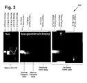
Figure 3 presents a diagram illustrating a rendering through progressively larger filter widths with and without filter kernel interpolation for seamless mipmap filtering, according to one embodiment of the present invention. Diagram 300 ofFigure 3 includesmipmap set 330, renderedscene 355a, and renderedscene 355b. Mipmap set 300 includes mipmaps 331a-331e. Renderedscene 355a includes filtered textures 350a-350c andmipmap transitions 332a-332b. Renderedscene 355b includes filtered textures 350d-350f. With regards toFigure 3 , it should be noted that mipmap set 330 corresponds to mipmap set 130 fromFigure 1 , and that renderedscenes 355a-355b correspond to renderedscene 155. -
Figure 2b takes a different approach than the method used forFigure 2a . Instead of interpolating kernel weights as inFigure 2a, Figure 2b focuses on interpolating index positions and using those interpolated index positions to determine kernel weights. Focusing onFigure 3 , it can be seen that mipmap set 330 has been generated using a box prefilter, with the original texture or mipmap 331a comprising a single white texel in a one-dimensional 16-texel array. Examining renderedscene 355a, it should be apparent that without using interpolation or lerping, any filter kernel using mipmaps will result in the appearance of position shifts or discontinuities at mipmap transitions such asmipmap transitions 332a-332b. This is also demonstrated by the apparently shifting texel position in mipmap set 330 indicated by the arrow. While generally it may be impossible in practice to shift filtered textures 350a-350c back into alignment due to differing shifts for each texel, if the prefilter is a box prefilter, then it is possible to realign the result by shifting the texels themselves during filter convolution. Thus, a new interpolation technique named "x-lerping" shall be utilized to realign the slices of filtered textures 350a-350c into a clean and seamless continuous result shown by filtered textures 350d-350f of renderedscene 355b. In other words, the "x-lerping" technique adjusts the positions of texels to offset the discontinuities introduced by the box prefilter:x'¡ = x¡ + λ/2 if i is even x'i = xi - λ/2 if i is odd - As with filter kernel value interpolation, filter kernel position interpolation does not require access or kernel filter processing of additional mipmap levels other than the higher resolution mipmap level L. Moreover, with filter kernel position interpolation, improved visual quality may result, kernel weights only need to be computed for a single mipmap level L, and positions may be interpolated separately even with a non-separable kernel such as the elliptical gaussian. However, filter kernel position interpolation is only applicable to a variable-width filter kernel with mipmaps generated using a box prefilter as in
Figure 3 , unlike the more generally applicable filter kernel value interpolation method. Thus, either filter kernel position interpolation or filter kernel value interpolation may prove to be more suitable depending on the particular requirements of a renderer or application. - To discuss in further detail, a general convolution equation for
Figure 2b may be written as follows:
where x is a 1-tuple representing a texel index position. Of course, in alternative embodiments, x could be an n-tuple for filtering n-dimensional textures, such as two-dimensional or three-dimensional textures. However, a 1-tuple is selected for simplicity. Assuming a variable-width filter kernel, applying the contributions of texel 232a or texel a andtexel 232b or texel b results in the following:
wherein x'a corresponds to interpolatedindex 249a and x'b corresponds to interpolated index 249b, each index interpolated towardstexel 232c of mipmap 231b as shown inFigure 2b . Since it is already known that a box prefilter was used to generate mipmaps 231a-231b, the data value dc fortexel 232c or texel c can be derived by a simple average as indicated above withFigure 2a . - To confirm that this x-lerping method is providing correct results, it may be instructive to use a test case at the verge of a mipmap transition. Thus, given:
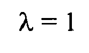


and combining with the equation for fab and dc as listed above, the result is:
which matches the contribution oftexel 232c after the transition. It should be noted that the extra factor of 2 drops out during kernel normalization since an extra factor of 2 will be included in the denominator during convolution and cancelled out, and the division by 2 reflects the difference in resolution betweenmipmap 231a and mipmap 231 b. As a result of the filter kernel position interpolation process shown inFigure 2b and the x-lerping interpolation described above, a seamless rendering similar to renderedscene 355b ofFigure 3 can be generated, again without ever needing to access the texels of mipmap 231b. -
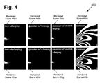
Figure 4 presents a diagram illustrating filter kernel interpolation for seamless mipmap filtering using several different filter kernels with or without x-lerping, according to one embodiment of the present invention. Diagram 400 ofFigure 4 includes rendered scenes 455a-455h. With regards toFigure 4 , it should be noted that rendered scenes 455a-455h correspond to renderedscene 155 fromFigure 1 . - Although filter kernel value interpolation results in an interpolation identical to the traditional interpolation or lerping process, filter kernel position interpolation provides results that may appear of higher quality with fewer artifacts resulting from mipmap transitions.
Figure 4 highlights these differences by showing rendered scenes 455a-455d produced with traditional mipmap interpolation techniques and renderedscenes 455e-455h resulting from x-lerping. As shown inFigure 1 , renderedscenes 455a and 455e correspond to a tent filter kernel, renderedscenes scenes scenes - Comparing rendered
scene 455d and renderedscene 455h, for example, a discontinuous gap artifact can be plainly observed towards the upper-left of the curve in renderedscene 455d, whereas the curve is smooth throughout without any abrupt discontinuities in renderedscene 455h. Similarly, rendered scene 455a appears to have similar gap artifacts whereas the corresponding x-lerped renderedscene 455e has none. As a result, textures using x-lerping for interpolation may benefit from smoother rendering of textures while minimizing distracting artifacts. - However, even with x-lerping, there is still the problem of C1 discontinuities at mipmap transition points where the texel shift suddenly changes direction. This is most easily observed in rendered
scene 455e, where it appears that the rendering is changing directions up and down at each mipmap transition. Although the gaussian filter for renderedscenes scene 455b. To avoid this sudden shift, the interpolation fraction may be smoothed, for example:
where λ' is the smoothed interpolation fraction to replace the standard interpolation fraction λ used throughout the equations described above. The effects of this smoothing can be observed in renderedscenes -
Figure 5 shows a flowchart describing the steps, according to one embodiment of the present invention, by which a rendering device may implement filter kernel interpolation for seamless filtering of transitions within a plurality of mipmaps. Certain details and features have been left out offlowchart 500 that are apparent to a person of ordinary skill in the art. For example, a step may comprise one or more substeps or may involve specialized equipment or materials, as known in the art. Whilesteps 510 through 550 indicated inflowchart 500 are sufficient to describe one embodiment of the present invention, other embodiments of the invention may utilize steps different from those shown inflowchart 500. - Referring to step 510 of
flowchart 500 inFigure 5 andenvironment 100 ofFigure 1 , step 510 offlowchart 500 comprisesprocessor 111 ofrendering device 110 choosingfilter kernel 145. As previously discussed,filter kernel 145 may be any suitable filter kernel, such as tent, gaussian, B-spline, or some other filter function. - Referring to step 520 of
flowchart 500 inFigure 5 andenvironment 100 ofFigure 1 , step 520 offlowchart 500 comprisesprocessor 111 ofrendering device 110 determining a filter width for use withfilter kernel 145 chosen fromstep 510. As previously discussed,rendering program 115 may determine a projected surface for texture mapping base-image texture 120 based on a particular camera view. Afterrendering program 115 determines the resolution required for texture mapping, it can then determine the proper filter width to use. - Referring to step 530 of
flowchart 500 inFigure 5 andenvironment 100 ofFigure 1 , step 530 offlowchart 500 comprisesprocessor 111 ofrendering device 110 selecting a first mipmap and a second mipmap from mipmap set 130, where the first mipmap has a mipmap level based on the filter width determined instep 520, and the second mipmap has a mipmap level one higher than the first mipmap. In one embodiment, this is the same as the equation as previously discussed:
wherein w represents the filter width determined fromstep 520, the first mipmap has a mipmap level L, and the second mipmap has a mipmaplevel L+ 1. Similar formulations using, for example, a ceiling function or a constant subtractive offset may be used as well. Continuing with the example used instep 520, if the filter width fromstep 520 is determined to be 10 pixels, then:
- As a result, the first mipmap has a
mipmap level 3 and the second mipmap has amipmap level 4 if the filter width fromstep 520 is 10 pixels. - Referring to step 540 of
flowchart 500 inFigure 5 andenvironment 100 ofFigure 1 , step 540 offlowchart 500 comprisesprocessor 111 ofrendering device 110 applyinginterpolation 135 onfilter kernel 145 chosen fromstep 510 to generate an interpolated filter kernel, orfilter kernel 145 using interpolatedkernel weights 140. The step ofinterpolation 135 is based onprefilter 125 andmipmaps 131d-131e selected fromstep 530. Two alternative approaches to implementinginterpolation 135 have been discussed in detail: filter kernel value interpolation, which is described withFigure 2a , and filter kernel position interpolation with x-lerping, which is described withFigure 2b above. As previously noted, ifprefilter 125 is a box filter, then the implementation of these filter kernel interpolations can simplify mathematically into particularly efficient implementations. Each method has its own advantages and limitations, so the selection of a particular interpolation implementation may depend on the particular requirements of a rendering project. At the end ofstep 540, the result is the creation of interpolatedkernel weights 140, ready to use withfilter kernel 145 to apply to any texture data, such asmipmap 131d. - Referring to step 550 of
flowchart 500 inFigure 5 andenvironment 100 ofFigure 1 , step 550 offlowchart 500 comprisesprocessor 111 ofrendering device 110 applyingfilter kernel 145 using interpolatedkernel weights 140 generated fromstep 540 to mipmap 131d selected fromstep 530 to generate filteredtexture 150 having a seamless filtering between mipmaps 131d-131e selected fromstep 530. This seamless filtering is due to the combination ofsteps Figures 3 and4 above. In addition,processor 111 may optionally smoothen an interpolation fraction used forfilter kernel 145 as previously discussed. Filteredtexture 150 may then be combined with other filtered textures into renderedscene 155 for output to display 160 or for writing to storage for future output to display 160 or another display. - As the described invention is applicable to any rendering pipeline that uses mipmaps, it has broad applicability to a wide range of rendering systems such as, for example, RenderMan for generating film quality animation, OpenGL or DirectX for real-time rendering applications such as simulations or videogames, and hardware accelerated video cards or specialized rendering hardware. More specifically, in situations where large quantities of high quality textures and associated mipmaps need to be accessed with minimal I/O penalties such as large networked server rendering clusters, the described invention may help make more efficient use of existing computing resources while also providing improved image rendering quality. This may be of particular importance to 3D film rendering studios having limited budgets for constantly upgrading hardware infrastructure.
- From the above description of the invention it is manifest that various techniques can be used for implementing the concepts of the present invention without departing from its scope. Moreover, while the invention has been described with specific reference to certain embodiments, a person of ordinary skills in the art would recognize that changes can be made in form and detail without departing from the spirit and the scope of the invention. As such, the described embodiments are to be considered in all respects as illustrative and not restrictive. It should also be understood that the invention is not limited to the particular embodiments described herein, but is capable of many rearrangements, modifications, and substitutions without departing from the scope of the invention.
Claims (14)
- A method of implementing a filter kernel interpolation for seamless filtering of transitions within a plurality of mipmaps derived from a base-image texture filtered using a prefilter, the method comprising:determining a filter width in pixels for use with a filter kernel, the pixels corresponding to texels of the base-image texture;selecting a first mipmap and a second mipmap from the plurality of mipmaps wherein the first mipmap has a mipmap level based on the filter width and the second mipmap has a mipmap level one higher than the first mipmap;applying interpolation on the filter kernel based on the prefilter, the first mipmap, and the second mipmap to generate an interpolated filter kernel; andapplying the interpolated filter kernel using texels of the first mipmap to generate a filtered texture having a seamless filtering of a transition between the first mipmap and the second mipmap.
- The method of claim 1, wherein the prefilter is a box prefilter.
- The method of claim 2, wherein the filter kernel uses a variable width.
- The method of claim 3, wherein applying the interpolation interpolates a position of each texel in the first mipmap towards a corresponding texel in the second mipmap.
- The method of claim 1, wherein applying the interpolation:determines a first kernel weight and second kernel weight of every two adjacent texels from the first mipmap and a third kernel weight of a corresponding texel from the second mipmap; andinterpolates the first kernel weight and the second kernel weight towards the third kernel weight for the every two adjacent texels from the first mipmap.
- The method of claim 1, wherein each texel is an n-tuple in an n dimensional domain, wherein n is at least two.
- The method of claim 6, wherein n is equal to three.
- The method of claim 6, wherein the applying of the interpolated filter kernel is separable into each dimension.
- The method of claim 6, wherein the filter kernel is non-separable.
- The method of claim 1, wherein the applying of the interpolated filter kernel uses anisotropy.
- The method of claim 10, wherein the applying of the interpolated filter kernel uses ripmaps or asymmetric reductions of the base-image texture.
- The method of claim 1, wherein the applying the interpolation uses a smoothing function to remove position shifting artifacts attributable to a C1 discontinuity caused by the first mipmap and the second mipmap transitioning to adjacent mipmap levels.
- The method of claim 1 further comprising outputting the filtered texture to a display.
- A rendering device having a memory and a processor, and adapted to perform the method of any of claims 1 to 13.
Applications Claiming Priority (1)
| Application Number | Priority Date | Filing Date | Title |
|---|---|---|---|
| US12/459,560 US9082216B2 (en) | 2009-07-01 | 2009-07-01 | System and method for filter kernel interpolation for seamless mipmap filtering |
Publications (1)
| Publication Number | Publication Date |
|---|---|
| EP2270753A1 true EP2270753A1 (en) | 2011-01-05 |
Family
ID=42983402
Family Applications (1)
| Application Number | Title | Priority Date | Filing Date |
|---|---|---|---|
| EP20100004960 Withdrawn EP2270753A1 (en) | 2009-07-01 | 2010-05-11 | System and method for intermediate mipmap level generation |
Country Status (3)
| Country | Link |
|---|---|
| US (1) | US9082216B2 (en) |
| EP (1) | EP2270753A1 (en) |
| NZ (1) | NZ585197A (en) |
Families Citing this family (6)
| Publication number | Priority date | Publication date | Assignee | Title |
|---|---|---|---|---|
| US9626789B2 (en) * | 2013-05-07 | 2017-04-18 | Advanced Micro Devices, Inc. | Implicit texture map parameterization for GPU rendering |
| US10354432B2 (en) | 2016-01-15 | 2019-07-16 | Intel Corporation | Texture space shading and reconstruction for ray tracing |
| US10395408B1 (en) * | 2016-10-14 | 2019-08-27 | Gopro, Inc. | Systems and methods for rendering vector shapes |
| US11361477B2 (en) * | 2020-01-30 | 2022-06-14 | Unity Technologies Sf | Method for improved handling of texture data for texturing and other image processing tasks |
| CN116324689A (en) | 2020-10-30 | 2023-06-23 | 海信视像科技股份有限公司 | Display device, geometric figure recognition method and multi-layer overlay display method |
| CN115243094B (en) * | 2020-12-22 | 2024-10-01 | 海信视像科技股份有限公司 | A display device and a multi-layer overlay method |
Citations (2)
| Publication number | Priority date | Publication date | Assignee | Title |
|---|---|---|---|---|
| EP0447227A2 (en) * | 1990-03-16 | 1991-09-18 | Hewlett-Packard Company | Method and apparatus for generating textured graphics primitives in frame buffer computer graphics systems |
| US6304268B1 (en) * | 1997-06-26 | 2001-10-16 | S3 Graphics Co., Ltd. | Trilinear texture filtering of two levels of detail based on a single level of detail |
Family Cites Families (26)
| Publication number | Priority date | Publication date | Assignee | Title |
|---|---|---|---|---|
| JP2673101B2 (en) | 1994-08-29 | 1997-11-05 | インターナショナル・ビジネス・マシーンズ・コーポレイション | Computer graphics equipment |
| US6005582A (en) * | 1995-08-04 | 1999-12-21 | Microsoft Corporation | Method and system for texture mapping images with anisotropic filtering |
| US6331856B1 (en) | 1995-11-22 | 2001-12-18 | Nintendo Co., Ltd. | Video game system with coprocessor providing high speed efficient 3D graphics and digital audio signal processing |
| US6333743B1 (en) | 1997-10-23 | 2001-12-25 | Silicon Graphics, Inc. | Method and apparatus for providing image and graphics processing using a graphics rendering engine |
| US6421048B1 (en) | 1998-07-17 | 2002-07-16 | Sensable Technologies, Inc. | Systems and methods for interacting with virtual objects in a haptic virtual reality environment |
| US6292193B1 (en) * | 1998-07-30 | 2001-09-18 | Compaq Computer Corporation | Techniques for anisotropic texture mapping using multiple space-invariant filtering operations per pixel |
| AU5686299A (en) | 1998-08-20 | 2000-03-14 | Raycer, Inc. | Method and apparatus for generating texture |
| US6947057B2 (en) | 2000-01-11 | 2005-09-20 | Sun Microsystems, Inc. | Rendering lines with sample weighting |
| US6583787B1 (en) | 2000-02-28 | 2003-06-24 | Mitsubishi Electric Research Laboratories, Inc. | Rendering pipeline for surface elements |
| US6850243B1 (en) | 2000-12-07 | 2005-02-01 | Nvidia Corporation | System, method and computer program product for texture address operations based on computations involving other textures |
| US6778181B1 (en) | 2000-12-07 | 2004-08-17 | Nvidia Corporation | Graphics processing system having a virtual texturing array |
| JPWO2003009125A1 (en) | 2001-07-19 | 2004-11-11 | ソニー株式会社 | Arithmetic device and image processing device |
| EP1461775A2 (en) * | 2001-12-20 | 2004-09-29 | Koninklijke Philips Electronics N.V. | Image rendering apparatus and method using mipmap texture mapping |
| US6753870B2 (en) | 2002-01-30 | 2004-06-22 | Sun Microsystems, Inc. | Graphics system configured to switch between multiple sample buffer contexts |
| US6819324B2 (en) | 2002-03-11 | 2004-11-16 | Sun Microsystems, Inc. | Memory interleaving technique for texture mapping in a graphics system |
| US7324116B2 (en) | 2002-06-20 | 2008-01-29 | Microsoft Corporation | Systems and methods for providing controllable texture sampling |
| TWI249144B (en) * | 2003-02-21 | 2006-02-11 | Via Tech Inc | Single level MIP filtering algorithm for anisotropic texturing |
| ATE454681T1 (en) | 2003-04-15 | 2010-01-15 | Nxp Bv | COMPUTER GRAPHICS PROCESSOR AND METHOD FOR GENERATING A COMPUTER GRAPHICS IMAGE |
| EP1494175A1 (en) | 2003-07-01 | 2005-01-05 | Koninklijke Philips Electronics N.V. | Selection of a mipmap level |
| US7672476B2 (en) | 2005-01-26 | 2010-03-02 | Pixar | Bandlimited noise for computer graphics |
| US7626591B2 (en) * | 2006-01-24 | 2009-12-01 | D & S Consultants, Inc. | System and method for asynchronous continuous-level-of-detail texture mapping for large-scale terrain rendering |
| US8203564B2 (en) | 2007-02-16 | 2012-06-19 | Qualcomm Incorporated | Efficient 2-D and 3-D graphics processing |
| US7872648B2 (en) | 2007-06-14 | 2011-01-18 | Microsoft Corporation | Random-access vector graphics |
| AU2008275873B2 (en) | 2007-07-19 | 2013-06-06 | Disney Enterprises, Inc. | Methods and apparatus for multiple texture map storage and filtering |
| US8040355B2 (en) | 2007-07-23 | 2011-10-18 | Disney Enterprises, Inc. | Three-dimensional location-based texture transfers |
| US8217940B2 (en) | 2007-07-23 | 2012-07-10 | Disney Enterprises, Inc. | Directable lighting method and apparatus |
-
2009
- 2009-07-01 US US12/459,560 patent/US9082216B2/en active Active
-
2010
- 2010-05-07 NZ NZ585197A patent/NZ585197A/en not_active IP Right Cessation
- 2010-05-11 EP EP20100004960 patent/EP2270753A1/en not_active Withdrawn
Patent Citations (2)
| Publication number | Priority date | Publication date | Assignee | Title |
|---|---|---|---|---|
| EP0447227A2 (en) * | 1990-03-16 | 1991-09-18 | Hewlett-Packard Company | Method and apparatus for generating textured graphics primitives in frame buffer computer graphics systems |
| US6304268B1 (en) * | 1997-06-26 | 2001-10-16 | S3 Graphics Co., Ltd. | Trilinear texture filtering of two levels of detail based on a single level of detail |
Non-Patent Citations (1)
| Title |
|---|
| EWINS J P ET AL: "MIP-MAP LEVEL SELECTION FOR TEXTURE MAPPING", IEEE TRANSACTIONS ON VISUALIZATION AND COMPUTER GRAPHICS, IEEE SERVICE CENTER, LOS ALAMITOS, CA, US LNKD- DOI:10.1109/2945.765326, vol. 4, no. 4, 1 October 1998 (1998-10-01), pages 317 - 329, XP000831199, ISSN: 1077-2626 * |
Also Published As
| Publication number | Publication date |
|---|---|
| NZ585197A (en) | 2010-12-24 |
| US20110001756A1 (en) | 2011-01-06 |
| US9082216B2 (en) | 2015-07-14 |
Similar Documents
| Publication | Publication Date | Title |
|---|---|---|
| US8098258B2 (en) | Methods and apparatus for multiple texture map storage and filtering | |
| US9013499B2 (en) | Methods and apparatus for multiple texture map storage and filtering including irregular texture maps | |
| US9171390B2 (en) | Automatic and semi-automatic generation of image features suggestive of motion for computer-generated images and video | |
| DeBry et al. | Painting and rendering textures on unparameterized models | |
| Burley et al. | Ptex: Per‐face texture mapping for production rendering | |
| Aliaga | Visualization of complex models using dynamic texture-based simplification | |
| WO2008013605A1 (en) | Real-time gpu rendering of piecewise algebraic surfaces | |
| US20080074415A1 (en) | Method, medium and apparatus rendering 3D graphic data | |
| US9082216B2 (en) | System and method for filter kernel interpolation for seamless mipmap filtering | |
| WO2006094199A2 (en) | Hybrid hardware-accelerated relighting system for computer cinematography | |
| US12094143B2 (en) | Image-based environment reconstruction | |
| Majercik et al. | Scaling probe-based real-time dynamic global illumination for production | |
| WO2006048961A1 (en) | Drawing device and drawing method | |
| US12243164B2 (en) | Method for generating a hierarchical data structure, hierarchical data structure, and method for streaming three-dimensional objects | |
| KR20240163125A (en) | Ultra high resolution upscaling | |
| KR20240169001A (en) | Locking mechanism for image classification | |
| CN120318422A (en) | A high-fidelity 3D reconstruction method for specular reflection planes | |
| Breslav et al. | Dynamic 2D patterns for shading 3D scenes | |
| Zhang et al. | When a tree model meets texture baking: an approach for quality-preserving lightweight visualization in virtual 3D scene construction | |
| Iglesias‐Guitian et al. | Pixel History Linear Models for Real‐Time Temporal Filtering | |
| Fajardo et al. | Stochastic texture filtering | |
| Besenthal et al. | Multi-resolution rendering for computationally expensive lighting effects | |
| KR100392516B1 (en) | real-time rendering method for noninterpolated volume data | |
| Lauritzen | Rendering antialiased shadows using warped variance shadow maps | |
| Gonzalez et al. | Continuity and interpolation techniques for computer graphics |
Legal Events
| Date | Code | Title | Description |
|---|---|---|---|
| PUAI | Public reference made under article 153(3) epc to a published international application that has entered the european phase |
Free format text: ORIGINAL CODE: 0009012 |
|
| AK | Designated contracting states |
Kind code of ref document: A1 Designated state(s): AL AT BE BG CH CY CZ DE DK EE ES FI FR GB GR HR HU IE IS IT LI LT LU LV MC MK MT NL NO PL PT RO SE SI SK SM TR |
|
| AX | Request for extension of the european patent |
Extension state: BA ME RS |
|
| 17P | Request for examination filed |
Effective date: 20110421 |
|
| 17Q | First examination report despatched |
Effective date: 20130328 |
|
| STAA | Information on the status of an ep patent application or granted ep patent |
Free format text: STATUS: THE APPLICATION IS DEEMED TO BE WITHDRAWN |
|
| 18D | Application deemed to be withdrawn |
Effective date: 20130806 |