EP2270577A1 - Method of and apparatus for generating a surface of an optical lens - Google Patents

Method of and apparatus for generating a surface of an optical lens Download PDF

Info

Publication number
EP2270577A1
EP2270577A1 EP09305634A EP09305634A EP2270577A1 EP 2270577 A1 EP2270577 A1 EP 2270577A1 EP 09305634 A EP09305634 A EP 09305634A EP 09305634 A EP09305634 A EP 09305634A EP 2270577 A1 EP2270577 A1 EP 2270577A1
Authority
EP
European Patent Office
Prior art keywords
difference data
optical
optical lens
ini
lens
Prior art date
Legal status (The legal status is an assumption and is not a legal conclusion. Google has not performed a legal analysis and makes no representation as to the accuracy of the status listed.)
Withdrawn
Application number
EP09305634A
Other languages
German (de)
French (fr)
Inventor
Pascal Allione
Fabien Muradore
Jordan Brouns
Current Assignee (The listed assignees may be inaccurate. Google has not performed a legal analysis and makes no representation or warranty as to the accuracy of the list.)
EssilorLuxottica SA
Original Assignee
Essilor International Compagnie Generale dOptique SA
Priority date (The priority date is an assumption and is not a legal conclusion. Google has not performed a legal analysis and makes no representation as to the accuracy of the date listed.)
Filing date
Publication date
Application filed by Essilor International Compagnie Generale dOptique SA filed Critical Essilor International Compagnie Generale dOptique SA
Priority to EP09305634A priority Critical patent/EP2270577A1/en
Priority to EP10726517A priority patent/EP2449420A1/en
Priority to PCT/EP2010/059235 priority patent/WO2011000846A1/en
Priority to US13/381,702 priority patent/US9002491B2/en
Priority to CN201080038355.XA priority patent/CN102483525B/en
Publication of EP2270577A1 publication Critical patent/EP2270577A1/en
Withdrawn legal-status Critical Current

Links

Images

Classifications

    • G—PHYSICS
    • G02—OPTICS
    • G02C—SPECTACLES; SUNGLASSES OR GOGGLES INSOFAR AS THEY HAVE THE SAME FEATURES AS SPECTACLES; CONTACT LENSES
    • G02C7/00—Optical parts
    • G02C7/02—Lenses; Lens systems ; Methods of designing lenses
    • G02C7/06—Lenses; Lens systems ; Methods of designing lenses bifocal; multifocal ; progressive
    • G02C7/061—Spectacle lenses with progressively varying focal power
    • G—PHYSICS
    • G02—OPTICS
    • G02C—SPECTACLES; SUNGLASSES OR GOGGLES INSOFAR AS THEY HAVE THE SAME FEATURES AS SPECTACLES; CONTACT LENSES
    • G02C2202/00—Generic optical aspects applicable to one or more of the subgroups of G02C7/00
    • G02C2202/08—Series of lenses, lens blanks

Definitions

  • the present invention relates to a method of and an apparatus for generating a surface of an optical lens.
  • the invention further relates to a method of and an apparatus for manufacturing an optical lens according to the surface generated by the method of the invention.
  • Multifocal ophthalmic lenses are a type of ophthalmic lens which in practice often comprise an aspherical face, and a face, which is spherical or toric, machined to match the lens to the wearer's prescription.
  • Progressive ophthalmic lenses usually comprise a far vision region, a near vision region, and a progressive corridor (or channel) there between.
  • the progressive corridor provides a gradual power progression from the far vision zone to the near vision zone without a dividing line or a prismatic jump.
  • the power in the various far, intermediate and near vision regions is determined by the prescription.
  • a prescription may for example define lens characteristics such as a power value for near vision, a power value for far vision, an addition, and possibly an astigmatism value with its axis and prism.
  • the dispensing of a particular progressive addition lens to a wearer involves selecting a progressive addition lens design from a range of available progressive addition lens designs based on certain visual requirements of the wearer.
  • a semi-finished lens blank having suitable optical characteristics is selected based on a prescription.
  • the semi-finished progressive lens blank comprises a front progressive multifocal surface and a back spherical surface.
  • the back surface of the semi-finished lens blank is then machined and polished to match the far-vision prescription.
  • An alternative method for producing multifocal progressive lenses uses less expensive single vision semi-finished lens blanks having a front spherical surface and a back spherical surface. Based on the optical lens parameters including prescription parameters and other wearer parameters, a single vision semi-finished lens blank having a suitable optical power is selected. A progressive surface design is then computed, for example obtained by optimisation, in accordance with optical lens parameters, and the back surface of the lens blank is machined and polished to produce the desired progressive surface. Although less expensive, this method for producing multifocal progressive lenses is relatively time consuming, partly due to the computational complexity of computing the progressive surface for each prescription.
  • the optimisation of an ophthalmic lens involves determining coefficients ⁇ of a surface equation S( ⁇ ) for defining a surface layer of one of the surfaces of the lens according to optical lens parameters denoted as ⁇ .
  • a lens surface may be composed of one or more surface layers and thus defined by one or more surface equations.
  • Optical lens parameters include wearing parameters A including optical prescription data such as prescribed values defining surface characteristics including sphere, cylinder, axe, prism power, addition, progression length etc; personalisation parameters, environmental factors, positioning parameters etc; for the wearing of the optical lens.
  • the surface equation coefficients ⁇ are determined such that a function F ⁇ ( ⁇ ) known as a merit function and which represents the optical defects of an optical lens, is kept to a minimum.
  • constraints may include prescription constraints relating to the near vision NV and the far vision FV zone or to lens thickness constraints, and the like.
  • the function F ⁇ ( ⁇ ) is not continuous in variables A.
  • the base curves chart which is an allocation law of the curvature radius of one of the surfaces of the lens can introduce discontinuities to the function F ⁇ ( ⁇ )
  • the method according to a first aspect of the invention enables the time for calculation of a customised surface of an optical lens according to a prescription to be reduced. Moreover the method allows the complete geometry of any customised lens associated with a given prescription to be provided without having to perform a full optimisation process for that particular prescription. From a predetermined set of optimised lenses corresponding to a set of prescriptions, an interpolation of the predetermined optimised surface equations leads to the generation of a desired target surface, an approximated target surface, which otherwise would have been optimised according to the conventional methods. Thus the method according to the invention enables lens information to be provided rapidly to an optician.
  • a method of manufacturing an optical lens surface comprising generating an optical surface S ⁇ ( ⁇ ) according to the methods of the invention and a step of manufacturing the optical surface according to the optical surface S ⁇ ( ⁇ ) generated.
  • Embodiments of the present invention may include apparatuses for performing the operations herein.
  • This apparatus may be specially constructed for the desired purposes, or it may comprise a general purpose computer or Digital Signal Processor ("DSP") selectively activated or reconfigured by a computer program stored in the computer.
  • DSP Digital Signal Processor
  • Such a computer program may be stored in a computer readable storage medium, such as, but is not limited to, any type of disk including floppy disks, optical disks, CD-ROMs, magnetic-optical disks, read-only memories (ROMs), random access memories (RAMs) electrically programmable read-only memories (EPROMs), electrically erasable and programmable read only memories (EEPROMs), magnetic or optical cards, or any other type of media suitable for storing electronic instructions, and capable of being coupled to a computer system bus.
  • a computer readable storage medium such as, but is not limited to, any type of disk including floppy disks, optical disks, CD-ROMs, magnetic-optical disks, read-only memories (ROMs), random access memories (RAMs) electrically programmable read-only memories (EPROMs), electrically erasable and programmable read only memories (EEPROMs), magnetic or optical cards, or any other type of media suitable for storing electronic instructions, and capable of being coupled to a computer system bus.
  • the surfaces may be calculated according to surface calculation methods known in the art, such as for example that described in European patent EP990939 which is incorporated herein by reference thereto.
  • the first difference data E( ⁇ j ) or optimised difference data is stored in a database from which it can be accessed for subsequent steps of the method.
  • the condition w j ⁇ ⁇ 0 if ⁇ j ⁇ O ⁇ ensures that the interpolation will be performed on a continuous function.
  • the method according to the embodiment of the invention includes two main operations.
  • a further operation of the method according to embodiments of the invention involves defining a rule for constructing weighting coefficients w j ⁇ ⁇ for the step of interpolation.
  • a preliminary step of the method according to certain embodiments of the invention may include changing the parameters ⁇ in order to work in conditions better adapted to the step of interpolation.
  • parameters ⁇ instead of working with prescription variables sphere, cylinder and axe, it may be more suitable in some cases to work with optical power in 3 particular optical directions, horizontal, vertical and diagonal.
  • the idea is to mesh the sub-sets O i sufficiently finely in order to obtain a more reliable approximation for obtaining the target surface.
  • Example of suitable polytopes include:
  • the set of optical lens parameters can be partitioned into triangles according to (sph, cyl) i values and into intervals along the dimensions consecrated to the axe and the addition.
  • the decomposition of an n-polytope into an association of n-simplexes respects the condition that the intersection between two distinct simplexes is either empty or is one of the (n-d) simplex cells (d ⁇ 1) of one of the 2 simplexes.
  • optical lens parameters ⁇ are characterised by Far Vision FV prescription parameters of sphere, cylinder and axe values, and addition values.
  • optical lens parameters ⁇ lie in a sub-space of 4 dimensions. If further parameters such as personalisation parameters are added, the parameter space will have additional dimensions.
  • the set of parameters ( sph,cyl ) i represents the subset of prescription data (sph,cyl) associated with the i ème base.
  • the interval [0,180[ corresponds to the axe intervals and the interval [0.75,4] corresponds to the addition intervals.
  • each of the sub-sets ( sph,cyl ) i is connected; i.e. they are not partitioned into disjointed parts and are polygons in the plane.
  • the partitioning of subsets O i into polytopes is carried out in two steps. In one step the subsets are partitioned by triangles in (sph, cyl) and in another step the intervals associated with the axe and addition are partitioned into sub-intervals.
  • the gap in values that can be seen on the graphical representations correspond to the different base changes; i.e. to the discontinuities of the optimisation solutions.
  • FIG. 3 is a graphical representation of a plane of prescription parameters of sphere value versus cylinder value and illustrates the manner in which the plane of prescription parameters is partitioned into triangles.
  • Each section pattern represents a base partitioned into 2 or 3 triangles by lines.
  • the representative prescriptions for validating the partitioning are shown in Figure 4 .
  • the maximum differences in sphere and cylinder values between the optimised surface difference data and the approximated surface difference data observed at the control points (PRP, MC, FV, NV) was found to be 0.05 D. This may be deemed as being sufficient. In order that this may be reduced a finer partitioning may be used.
  • Partitioning according to addition values can be carried out in a similar manner to partitioning according to axe values.
  • sub intervals of [0.75, 4.0] necessary for appropriately fitting the curves of sphere difference values and cylinder difference values at the control points as a function of the addition par straight segments are defined per base.
  • Figures 11 and 12 illustrate surface maps of sphere and cylinder values for optimised difference data and the difference data approximated for a given prescritpion and for an addition of 1.75D.
  • the partitioning of the optical lens parameters space into polytopes can be performed satisfacly or automatically.
  • a database of predetermined optimised surfaces may be built up over time and prescription labs may share surface data which has already been optimised.
  • the methods according to embodiments of the invention thus enable the calculation time for calculating a target optical surface to be reduced. This in turn enables information such as lens thicknesses to be provided more quickly to an optician without the need for a full optimisation process to be implemented for each lens prescription.

Landscapes

  • Health & Medical Sciences (AREA)
  • Ophthalmology & Optometry (AREA)
  • Physics & Mathematics (AREA)
  • General Health & Medical Sciences (AREA)
  • General Physics & Mathematics (AREA)
  • Optics & Photonics (AREA)
  • Eyeglasses (AREA)

Abstract

A method of generating a target surface S (» ) of an optical lens according to optical lens parameters » , the method comprising: providing a set of L first surface difference data E(A j ) each first surface difference data E(A j ) corresponding to the surface difference between a pre-calculated surface S » j pc ± » j ¢ j = 1 , €¦ , L and an initial surface S » j ini j = 1 , €¦ , L , from which the target surface will be generated, according to the expression : E » j = S » j pc ± » j - S » j ini j = 1 , €¦ , L where » j ( j = 1,..., L ) correspond to the optical lens parameters of the pre-calculated optical lenses; providing a set of second surface difference data E (» ) corresponding to the surface difference between the target optical surface S (» ) and the initial surface S » €¾ ini by linear interpolation of the first surface difference data E (» j ) according to the expression: E Ü » €¾ = ˆ‘ j = 1 L w j » €¾ ¢ E » j , where w j » represents an interpolation coefficient; and; determining the target surface S (» ) by combining the second surface difference data E (» )and the inital surface S » €¾ ini according to the expression: S Ü » €¾ = E Ü » €¾ + S » €¾ ini

Description

  • The present invention relates to a method of and an apparatus for generating a surface of an optical lens. The invention further relates to a method of and an apparatus for manufacturing an optical lens according to the surface generated by the method of the invention.
  • Ophthalmic lens for the compensation of eyesight defects are well known. Multifocal ophthalmic lenses are a type of ophthalmic lens which in practice often comprise an aspherical face, and a face, which is spherical or toric, machined to match the lens to the wearer's prescription.
  • Progressive ophthalmic lenses usually comprise a far vision region, a near vision region, and a progressive corridor (or channel) there between. The progressive corridor provides a gradual power progression from the far vision zone to the near vision zone without a dividing line or a prismatic jump.
  • For multimodal lenses, the power in the various far, intermediate and near vision regions is determined by the prescription. A prescription may for example define lens characteristics such as a power value for near vision, a power value for far vision, an addition, and possibly an astigmatism value with its axis and prism.
  • Generally, the dispensing of a particular progressive addition lens to a wearer involves selecting a progressive addition lens design from a range of available progressive addition lens designs based on certain visual requirements of the wearer.
  • In a common method for producing progressive multifocal lenses according to optical lens parameters including prescription data, a semi-finished lens blank having suitable optical characteristics is selected based on a prescription. Typically the semi-finished progressive lens blank comprises a front progressive multifocal surface and a back spherical surface. The back surface of the semi-finished lens blank is then machined and polished to match the far-vision prescription.
  • An alternative method for producing multifocal progressive lenses uses less expensive single vision semi-finished lens blanks having a front spherical surface and a back spherical surface. Based on the optical lens parameters including prescription parameters and other wearer parameters, a single vision semi-finished lens blank having a suitable optical power is selected. A progressive surface design is then computed, for example obtained by optimisation, in accordance with optical lens parameters, and the back surface of the lens blank is machined and polished to produce the desired progressive surface. Although less expensive, this method for producing multifocal progressive lenses is relatively time consuming, partly due to the computational complexity of computing the progressive surface for each prescription.
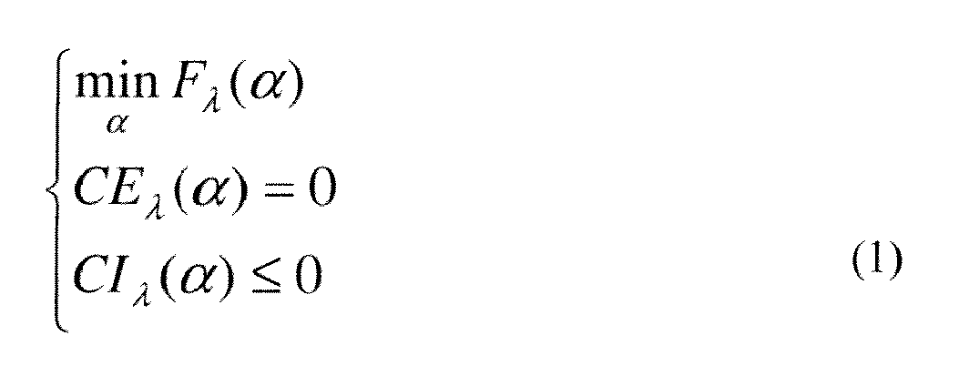
  • The optimisation of an ophthalmic lens involves determining coefficients α of a surface equation S(α) for defining a surface layer of one of the surfaces of the lens according to optical lens parameters denoted as λ. A lens surface may be composed of one or more surface layers and thus defined by one or more surface equations. Optical lens parameters include wearing parameters A including optical prescription data such as prescribed values defining surface characteristics including sphere, cylinder, axe, prism power, addition, progression length etc; personalisation parameters, environmental factors, positioning parameters etc; for the wearing of the optical lens. The surface equation coefficients α are determined such that a function F λ (α) known as a merit function and which represents the optical defects of an optical lens, is kept to a minimum.
  • In some cases in addition to coefficient α a set of equality constraints CE λ(α) = 0 and inequality constraints Clλ(α) ≤ 0 should be respected. These constraints may include prescription constraints relating to the near vision NV and the far vision FV zone or to lens thickness constraints, and the like.
  • The optimisation of an optical lens may thus be mathematically represented by the following problem: { min α ⁢ F λ α CE λ α = 0 CI λ α ≤ 0
    Figure imgb0001

    In many cases the function F λ(α) is not continuous in variables A. For example the base curves chart which is an allocation law of the curvature radius of one of the surfaces of the lens can introduce discontinuities to the function Fλ(α)
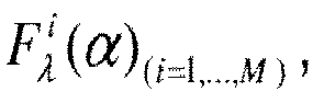
  • The set O of all optical lens parameters λ can be divided into M distinct and connected zones Oi (i=1...M) of optical lens parameters in which the functions F λ(α),CEλ(α) and CI λ(α) are continuous. The continuous functions associated with these zones are denoted as F λ i ⁢ α i = 1 , … , M ,
    Figure imgb0002
    and C ⁢ E λ i ⁢ α i = 1 , … , M
    Figure imgb0003
    and C ⁢ I λ i ⁢ α i = 1 , … , M .
    Figure imgb0004
  • This leads to the following representations: F λ α = { F λ 1 α if λ ∈ O 1 … F λ M α if λ ∈ O M
    Figure imgb0005
    C ⁢ E λ α = { C ⁢ E λ 1 α if λ ∈ O 1 … C ⁢ E λ M α if λ ∈ O M
    Figure imgb0006
    C ⁢ I λ α = { C ⁢ I λ 1 α if λ ∈ O 1 … C ⁢ I λ M α if λ ∈ O M
    Figure imgb0007
  • If we make the assumption that the optimisation problem represented by formula (1) has a unique solution, then the solutions of the problem are continuous in each zone O i(i=1,...,M).
  • When an order for a personalised optical lens defined by a set of optical lens parameters λ arrives in a prescription laboratory problem 1 is solved for each prescription using an adapted algorithm. Such a process is however time consuming and complex.
  • In view of the foregoing it would be desirable to reduce the complexity of the calculation design and to improve the reliability of the calculations in the design of a surface of an optical lens.
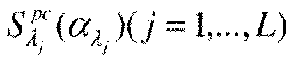
  • According to a first aspect of the invention, there is provided a method of generating a target surface S̃(λ̅) of an optical lens according to optical lens parameters λ̅, the method comprising:providing a set of L first surface difference data E(λj) each first surface difference data E(λj) corresponding to the surface difference between a pre-calculated surface S λ j pc α λ j ⁢ j = 1 , … , L
    Figure imgb0008
    and an initial surface S λ j ini j = 1 , … , L ,
    Figure imgb0009
    from which the target surface will be generated, according to the expression : E λ j = S λ j pc α λ j - S λ j ini j = 1 , … , L
    Figure imgb0010

    where λ j (j = 1,..., L) correspond to the optical lens parameters of optical lenses associated with the pre-calculated surfaces; providing a set of second surface difference data Ẽ(λ̅) corresponding to the surface difference between the target optical surface S̃(λ̅) and the initial surface S λ ‾ ini
    Figure imgb0011
    by linear interpolation of the first surface difference data E(λj) according to the expression: E ˜ λ ‾ = ∑ j = 1 L w j λ ‾ ⁢ E λ j ,
    Figure imgb0012
    where w j λ ‾
    Figure imgb0013
    represents an interpolation coefficient;
    and; determining the target surface S̃(λ̅) by combining the second surface difference data Ẽ(λ̅) and the inital surface S λ ‾ ini
    Figure imgb0014
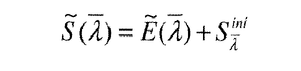
    according to the expression: S ˜ λ ‾ = E ˜ λ ‾ + S λ ‾ ini
    Figure imgb0015
  • The method according to a first aspect of the invention enables the time for calculation of a customised surface of an optical lens according to a prescription to be reduced. Moreover the method allows the complete geometry of any customised lens associated with a given prescription to be provided without having to perform a full optimisation process for that particular prescription. From a predetermined set of optimised lenses corresponding to a set of prescriptions, an interpolation of the predetermined optimised surface equations leads to the generation of a desired target surface, an approximated target surface, which otherwise would have been optimised according to the conventional methods. Thus the method according to the invention enables lens information to be provided rapidly to an optician.
  • According to a second aspect of the invention there is provided a method of manufacturing an optical lens surface comprising generating an optical surface S̃(λ̅) according to the methods of the invention and a step of manufacturing the optical surface according to the optical surface S̃(λ̅) generated.
  • Further optional features of embodiments of the invention are set out below:
    • ■ the interpolation coefficient w j λ ‾ = 0
      Figure imgb0016
      if λ j ∉ O λ̅ where O λ̅ corresponds to a parameter subset for which λ̅ ∈ O λ̅ from among M parameter subsets O i(i=1,...,M)
    • ■ the interpolation coefficients w j λ i = δ ij
      Figure imgb0017
      for (i,j=1,...,L) where δ ij represents the Kronecker symbol where δ ij =0 if i ≠ j and δ ij =1 si i=j.
    • ■ the optical lens parameters λ j (j = 1,..., L) are modified in order to optimise the step of interpolation.
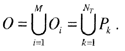
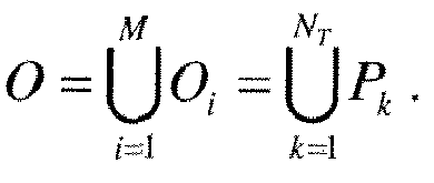
    • ■ the method further includes the step of covering the pre-defined parameter subsets O i(i=1,...,M) by a one or more of NT n-polytopes Pk (k = 1,NT ) the vertices of which make up part of the optical lens parameters λ j (j = 1,...,L) according to the expression: O = ∪ i = 1 M O i = ∪ k = 1 N T P k .
      Figure imgb0018
      According to another aspect, the invention relates to a computer program product comprising one or more stored sequence of instructions accessible to a processor which, when executed by the processor, causes the processor to carry out the steps of a method according to the invention. The invention also relates to a computer readable medium carrying one or more sequences of instructions of the computer program product according to the invention.
  • Unless specifically stated otherwise, it will be appreciated that throughout the specification terms such as "computing", "calculating", "generating", or the like, refer to the action and/or processes of a computer or computing system, or similar electronic computing device, that manipulate and/or transform data represented as physical, such as electronic, quantities within the computing system's registers and/or memories into other data similarly represented as physical quantities within the computing system's memories, registers or other such information storage, transmission or display devices.
  • Embodiments of the present invention may include apparatuses for performing the operations herein. This apparatus may be specially constructed for the desired purposes, or it may comprise a general purpose computer or Digital Signal Processor ("DSP") selectively activated or reconfigured by a computer program stored in the computer. Such a computer program may be stored in a computer readable storage medium, such as, but is not limited to, any type of disk including floppy disks, optical disks, CD-ROMs, magnetic-optical disks, read-only memories (ROMs), random access memories (RAMs) electrically programmable read-only memories (EPROMs), electrically erasable and programmable read only memories (EEPROMs), magnetic or optical cards, or any other type of media suitable for storing electronic instructions, and capable of being coupled to a computer system bus.
  • The processes and displays presented herein are not inherently related to any particular computer or other apparatus. Various general purpose systems may be used with programs in accordance with the teachings herein, or it may prove convenient to construct a more specialized apparatus to perform the desired method. The desired structure for a variety of these systems will appear from the description below. In addition, embodiments of the present invention are not described with reference to any particular programming language. It will be appreciated that a variety of programming languages may be used to implement the teachings of the inventions as described herein.
  • In the context of the present invention, the following terms may be deemed to have meanings indicated herein below:
    • Near vision point NV relates to the point of a surface of a progressive addition lens through which the sight of the wearer passes when said wearer is in a reading position.
    • Far vision point FV relates to the point of a surface of a progressive addition lens through which the sight of the wearer passes when said wearer looks at infinity
    • near vision zone: zone of the lens that surrounds the near vision point, and within which the local optical characteristics of optical power and of astigmatism of the lens are substantially identical to those of the near vision point;
    • far vision zone: zone of the lens that surrounds the far vision point, and within which the local optical characteristics of optical power and of astigmatism of the lens are substantially identical to those at the far vision point;
    • addition of a progressive addition lens: difference between the value of optical power of the lens at the near vision point and that at the far vision point;
    • optical characteristics of a progressive addition lens: data on optical power, astigmatism, aberration, etc., relating to the modifications of a light beam that passes through the progressive addition lens;
    • prescription: set of optical characteristics of optical power, of astigmatism and, where relevant, of addition, determined by an ophthalmologist in order to correct the vision defects of an individual, for example by means of a lens positioned in front of his eye.
    • surface characteristics of a progressive addition lens: geometrical data relating to one face of the lens, such as values of average sphere, cylinder, axe at surface points, for example;
    • prism reference point (PRP) - point on the front surface of a lens at which the prismatic effect of the lens is determined;
    • mounting centre (MC) or Fitting Cross (FC)- point on the front surface of a lens used by the manufacturer as a reference point for positioning the lens in front of the eye.
  • Embodiments of the invention will now be described, by way of example only, and with reference to the following drawings in which:-
    • Figure 1 is a flow chart of steps of a method of generating a surface of an optical lens according to embodiments of the invention;
    • Figure 2A is a 3D graphical representation of FV and NV cylinder values of first difference data E(λj) for prescription parameters Axe=0, Add=2.0 according to an embodiment of the invention;
    • Figure 2B is a 3D graphical representation of FV and NV mean sphere values of first difference data E(λj) for prescription parameters Axe=0, Add=2.0 according to an embodiment of the invention;
    • Figure 3 is a graphical representation of partitioning of a plane of prescriptions into triangles;
    • Figure 4 is a graphical representation of a partitioned plane of validation prescriptions;
    • Figure 5A is a surface map of the mean sphere values of approximated difference data for a first prescription;
    • Figure 5B is a surface map of the mean sphere values of optimised difference data for the first prescription;
    • Figure 6A is a surface map of the cylinder values of approximated difference data for the first prescription;
    • Figure 6B is a surface map of the cylinder values of optimised difference data for the first prescription;
    • Figure 7 is a graphical representation of the partitioning of the interval of axes into 8 sub-intervals;
    • Figure 8A is a surface map of the mean sphere values of approximated difference data for the second prescription;
    • Figure 8B is a surface map of the mean sphere values of optimised difference data for the second prescription;
    • Figure 9A is a surface map of the cylinder values of approximated difference data for the second prescription;
    • Figure 9B is a surface map of the cylinder values of optimised difference data for the second prescription;
    • Figure 10A is a graphical representation of the variation in NV sphere values as a function of addition for a number of prescriptions of base 8.0;
    • Figure 10B is a graphical representation of the variation in PRP sphere values as a function of addition for a number of prescriptions of base 8.0;
    • Figure 10C is a graphical representation of the variation in FV sphere values as a function of addition for a number of prescriptions of base 8.0;
    • Figure 11A is a surface map of the mean sphere values of approximated difference data for a third prescription;
    • Figure 11B is a surface map of the mean sphere values of optimised difference data for the third prescription;
    • Figure 12A is a surface map of the cylinder values of approximated difference data for the second prescription; and
    • Figure 12B is a surface map of the cylinder values of optimised difference data for the second prescription.
  • A first embodiment of the method according to the invention will now be described with reference to Figures 1 to 4.
  • In an initial step E1 of the method, a predetermined number L of surfaces S λ j pc α λ j ⁢ j = 1 , … , L
    Figure imgb0019
    according to a set of L optical lens parameter data λ j (j = 1,..., L) are pre-calculated. The surfaces may be calculated according to surface calculation methods known in the art, such as for example that described in European patent EP990939 which is incorporated herein by reference thereto. In step E2 a set of L first surface difference data E(λj) is determined in which each surface difference data E(λj) defines a surface layer corresponding to the difference between a pre-calculated optimised surface S λ j pc α λ j ⁢ j = 1 , … , L
    Figure imgb0020
    and a corresponding initial surface S λ j ini j = 1 , … , L
    Figure imgb0021
    according to the expression : E λ j = S λ j pc α λ j - S λ j ini j = 1 , … , L
    Figure imgb0022

    The initial surface S λ j ini j = 1 , … , L
    Figure imgb0023
    acts as a starting point for the optimisation process for generating a target surface.
  • The first difference data E(λj) or optimised difference data is stored in a database from which it can be accessed for subsequent steps of the method.
  • In step E3, when a prescription for an optical lens according to an optical lens parameter data λ̅ is received, second surface difference data Ẽ(λ̅) or approximated difference data for defining the difference between the target optical surface S̃(λ̅) and the corresponding initial surface S λ ‾ ini
    Figure imgb0024
    is then approximated by linear interpolation of the pre-determined first difference data E(λj) according to the expression: E ˜ λ ‾ = ∑ j = 1 L w j λ ‾ ⁢ E λ j
    Figure imgb0025

    where w j λ ‾
    Figure imgb0026
    represents an interpolation coefficient.
  • The interpolation coefficient w j λ ‾ = 0
    Figure imgb0027
    if λ j ∉ O λ̅ where O λ̅ corresponds to a parameter subset or zone to which λ̅ belongs i.e. λ̅ ∈ O λ̅, from among M zones O i(i=1,...,M).
  • The condition w j λ ‾ = 0
    Figure imgb0028
    if λ j ∉ O λ̅ ensures that the interpolation will be performed on a continuous function. The interpolation coefficients w j λ i
    Figure imgb0029
    should respect the condition w j λ i = δ ij
    Figure imgb0030
    for (i,j=1,...,L) where δ ij represents the Kronecker symbol defined by δ ij =0 if i ≠ j and δ ij =1 if i=j. This means that if the optical lens parameters λ̅ of the received prescription for the target surface correspond to one of those stocked in the data base, the interpolation should remain coherent with the optimisation calculation.
  • In step E4 the final approximate customised or target surface S̃(λ̅) according to the prescription is determined by combining the second difference data Ẽ(λ̅) and the initial surface S λ ini
    Figure imgb0031
    according to the expression: S ˜ λ ‾ = E ˜ λ ‾ + S λ ‾ ini
    Figure imgb0032
  • The method according to the embodiment of the invention includes two main operations. A first sampling operation consists in defining for each sub-set O i(i=1,...,M) in which the solution to equation (1) is continuous in variable λ, the sample points λj for which problem (1) will be solved. A further operation of the method according to embodiments of the invention involves defining a rule for constructing weighting coefficients w j λ ‾
    Figure imgb0033
    for the step of interpolation.
  • A preliminary step of the method according to certain embodiments of the invention may include changing the parameters λ in order to work in conditions better adapted to the step of interpolation. For example, instead of working with prescription variables sphere, cylinder and axe, it may be more suitable in some cases to work with optical power in 3 particular optical directions, horizontal, vertical and diagonal.
  • In the sampling operation the idea is to mesh the sub-sets Oi sufficiently finely in order to obtain a more reliable approximation for obtaining the target surface.
  • Assuming subset zones Oi are covered by a set of NT n-polytopes Pk (k = 1,...NT ) according to the expression O = ∪ k = 1 N T P k .
    Figure imgb0034
    The vertices of the n-polytopes form part of the optical lens parameters λ j (j = 1,..., L). The assumption is made that the covering is such that the intersection between two different polytopes is either empty or is one of the (n-d)-cells, where d ≥ 1, of one of the 2 polytopes where n corresponds to the number of optical lens parameters and the space dimension, and where (n-d) is thus less than n.
  • Example of suitable polytopes include:
    • ■ n-simplexes (triangles, tetrahedrons,...)
    • ■ parallelotopes (squares, parallelepiped,...)
  • For example, the set of optical lens parameters can be partitioned into triangles according to (sph, cyl)i values and into intervals along the dimensions consecrated to the axe and the addition.
  • In terms of interpolation given the optical lens parameters λ̅ included in the sub-set Oi, and by the decomposition of Oi, there is at least one polytope Pk respecting the conditions that λ̅ ∈ Pk . λ k l l = 1 , … , N
    Figure imgb0035
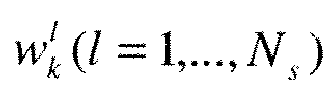
    represent the vertices of the polytope Pk , from the definition of a polytope, there is a series of real numbers w k l l = 1 , … , N s
    Figure imgb0036
    such that w k l ≥ 0 ,
    Figure imgb0037
    ∑ l = 1 N s w k l = 1
    Figure imgb0038
    and such that λ ‾ = ∑ l = 1 N s w k l ⁢ λ k l .
    Figure imgb0039
  • Coefficients w k l l = 1 , … , N s
    Figure imgb0040
    will be used for the interpolation of the first difference data E λ k l
    Figure imgb0041
    to provide second difference data Ẽ(λ̅) for determining the target surface. If the polytopes are of an n-simplex type, the coefficients w k l l = 1 , … , N s
    Figure imgb0042
    correspond to the barycentric coordinates of the point λ̅ with respect to the simplex Pk . Since any n-polytope can be decomposed into an association of n-simplexes the vertices of which being those of the n-polytope, the problem can be reduced to finding the barycentric coordinates of an n-simplex. The decomposition of an n-polytope into an association of n-simplexes respects the condition that the intersection between two distinct simplexes is either empty or is one of the (n-d) simplex cells (d≥1) of one of the 2 simplexes.
  • The principle of the method according to the embodiment of the invention will now be illustrated for the case of a lens A (of type Physio). In the example of lens A the optical lens parameters λ are characterised by Far Vision FV prescription parameters of sphere, cylinder and axe values, and addition values.
  • Thus the optical lens parameters λ lie in a sub-space of 4 dimensions. If further parameters such as personalisation parameters are added, the parameter space will have additional dimensions. In this case the sub-sets O i(i=1,...,M) come directly from the base design of the product. In this example, there are 6 bases (1.75 2.75 3.75 5.25 6.50 8.00) Thus the number of parameter zones M=6 and the sub sets Oi of parameters are decomposed according to the following Cartesian product: Oi = (sph,cyl) ¡ × [0,180[×[0.75,4].
  • The set of parameters (sph,cyl) i represents the subset of prescription data (sph,cyl) associated with the i ème base. The interval [0,180[ corresponds to the axe intervals and the interval [0.75,4] corresponds to the addition intervals. In the base designs for lens A each of the sub-sets (sph,cyl) i is connected; i.e. they are not partitioned into disjointed parts and are polygons in the plane.
  • In this embodiment the partitioning of subsets O i into polytopes is carried out in two steps. In one step the subsets are partitioned by triangles in (sph, cyl) and in another step the intervals associated with the axe and addition are partitioned into sub-intervals.
  • In order to carry out a partitioning in (sph, cyl) the variations of the surface difference data E(λ) according to the surface value and sphere value of the prescription parameters are analysed. The analysis can be carried out in the case where Axe=0 and Add=2.0 diopters. For each prescription the magnitudes of the average sphere and the cylinder values at the far vision FV and near vision NV points of the surface difference data are calculated, for example according to the method described in WO2007017766A2 which is incorporated herein by reference thereto. Figures 2A and 2B graphically illustrate the cylinder and sphere values for the set of prescriptions. Figure 2A illustrates the cylinders in NV and FV of the first surface difference data E λ j = S λ j α λ j - S λ j ini j = 1 , … , L
    Figure imgb0043
    for the set of prescriptions in which Axe=0 and Add=2.0. Figure 2B graphically illustrates the spheres in NV and FV of the first surface difference data E λ j = S λ j α λ j - S λ j ini j = 1 , … , L
    Figure imgb0044
    for the set of prescriptions in which Axe=0 and Add=2.0. The gap in values that can be seen on the graphical representations correspond to the different base changes; i.e. to the discontinuities of the optimisation solutions. Apart from these discontinuous zones the variation of sphere or cylinder quantities is relatively gradual and each zone can be easily approximated by a plane or preferably by several planes. A meshing based on several triangles is sufficient to ensure a good approximation between the optimised surfaces and the approximated surfaces. Figure 3 is a graphical representation of a plane of prescription parameters of sphere value versus cylinder value and illustrates the manner in which the plane of prescription parameters is partitioned into triangles. Each section pattern represents a base partitioned into 2 or 3 triangles by lines.
  • In order to validate the partitioning, the optimised surface and the approximated surface have been calculated for a representative set of prescriptions (in this case Axe =0, addition =2). The representative prescriptions for validating the partitioning are shown in Figure 4.
  • Figures 5 and 6 illustrate as an example the surface maps of the mean sphere and cylinder values of the optimised difference data and approximate difference data for the prescription (Sph=4.75, cyl=0.75, Axe=0, Add=2.0).
  • On the set of validation prescriptions the maximum differences in sphere and cylinder values between the optimised surface difference data and the approximated surface difference data observed at the control points (PRP, MC, FV, NV) was found to be 0.05 D. This may be deemed as being sufficient. In order that this may be reduced a finer partitioning may be used.
  • For partitioning according to the prescription axe, the variation of the sphere and cylinder values at the control points PRP, MC, FV, NV of the optimised difference data for a number of test prescriptions in each base was studied. For each base a set of sub-intervals on which the differences in the variable "axe" could be approximated by a straight segment was identified. In this way, for the base 2.75 the interval 0-180 degrees was partitioned into 8 sub-intervals as shown in Figure 7 which represents the variation of the NV sphere as a function of the axe for a number of prescriptions in this base.
  • For the set of 6 bases the interval 0-180 was divided in this way according to the following rules
    • Base 8.00 : 0 / 30 / 50 / 70 / 100 / 130 / 150 / 180
    • Base 6.50 : 0 / 20 / 50 / 70 / 90 / 110 / 120 / 140 / 180
    • Base 5.25 : 0 / 30 / 50 / 70 / 90 / 110 / 130 / 140 / 180
    • Base 3.75 : 0 / 30 / 50 / 70 / 90 / 120 / 140 / 150 / 180
    • Base 2.75 : 0 / 30 / 50 / 70 / 90 / 110 / 140 / 150 / 180
    • Base 1.75 : 0 / 30 / 50 / 70 / 90/ 120/ 140 / 180
  • With such partitioning the maximum differences obtained at the points of control are of the order of 0.12D for the same set of test prescriptions as illustrated in Figure 4 extended to a number of different axes. In order to reduce these differences a finer partitioning of the axes per base can be used.
  • Figures 8 and 9 respectively show an example of surface maps of mean sphere and cylinder values for optimised and approximated difference data for the prescription (Sph=3.25, Cyl=1.50, Axe=80, Add=2.0) corresponding to the base 6.50.
  • Partitioning according to addition values can be carried out in a similar manner to partitioning according to axe values. After analysis of the variation of the optimum difference data according to the addition, sub intervals of [0.75, 4.0] necessary for appropriately fitting the curves of sphere difference values and cylinder difference values at the control points as a function of the addition par straight segments are defined per base. Thus Figure 10 presents for a certain number of prescriptions of base 8.0 sphere variations at NV, PRP and FV of the optimised difference data as a function of the addition (axe=0).
  • It can be seen from these figures that the dependence on addition of the spheres of the difference data is virtually linear locally contrary to that for the axe.
  • In studying the variations base by base the interval [0.75, 4.0] has been partitioned as follows:
    • Base 8.00 : 0,75 / 2,00 2,50 / 2,75 / 4,00
    • Base 6.50 : 0,75 / 1,50 / 2,00 / 2,50 / 4,00
    • Base 5.25 : 0,75 / 1,50 / 2,00 / 2,50 / 3,00 / 4,00
    • Base 3.75 : 0,75 / 1,50 / 2,00 / 2,25 / 2,75 / 3,25 / 4,00
    • Base 2.75 : 0,75 / 1,50 / 2,00 3,75 / 4,00
    • Base 1.75 : 0,75 / 1,25 / 1,50 / 2,00 / 3,25 / 4,00
  • Figures 11 and 12 illustrate surface maps of sphere and cylinder values for optimised difference data and the difference data approximated for a given prescritpion and for an addition of 1.75D.
  • The partitioning of the optical lens parameters space into polytopes can be performed manuelly or automatically. A database of predetermined optimised surfaces may be built up over time and prescription labs may share surface data which has already been optimised.
  • The methods according to embodiments of the invention thus enable the calculation time for calculating a target optical surface to be reduced. This in turn enables information such as lens thicknesses to be provided more quickly to an optician without the need for a full optimisation process to be implemented for each lens prescription.
  • Many further modifications and variations will suggest themselves to those versed in the art upon making reference to the foregoing illustrative embodiments, which are given by way of example only and which are not intended to limit the scope of the invention, that being determined solely by the appended claims. In particular the different features from different embodiments may be interchanged, where appropriate.

Claims (8)

  1. A method of generating a target surface S̃(λ̅) of an optical lens according to optical lens parameters λ, the method comprising:
    providing a set of L first surface difference data E(λj) each first surface difference data E(λj) corresponding to the surface difference between a pre-calculated surface S λ j pc α λ j ⁢ j = 1 , … , L
    Figure imgb0045
    and an initial surface S λ j ini j = 1 , … , L ,
    Figure imgb0046
    from which the target surface will be generated, according to the expression : E λ j = S λ j pc α λ j - S λ j ini j = 1 , … , L
    Figure imgb0047

    where λ j (j = 1,..., L) correspond to the optical lens parameters of optical lenses associated with the pre-calculated surfaces;
    providing a set of second surface difference data Ẽ(λ̅) corresponding to the surface difference between the target optical surface S̃(λ̅) and the initial surface S λ ‾ ini
    Figure imgb0048
    by linear interpolation of the first surface difference data E(λj) according to the expression: E ˜ λ ‾ = ∑ j = 1 L w j λ ‾ ⁢ E λ j ,
    Figure imgb0049
    where w j λ ‾
    Figure imgb0050
    represents an interpolation coefficient;
    and;
    determining the target surface S̃(λ̅) by combining the second surface difference data Ẽ(λ̅) and the inital surface S λ ‾ ini
    Figure imgb0051
    according to the expression: S ˜ λ ‾ = E ˜ λ ‾ + S λ ‾ ini
    Figure imgb0052
  2. A method according to claim 1, wherein the interpolation coefficient w j λ ‾ = 0
    Figure imgb0053
    if λ j ∉ O λ̅
    where O λ̅ corresponds to a parameter subset for which λ̅ ∈ O λ̅ from among M parameter subsets O i(i=1,...,M)
  3. A method according to claim 1 or 2, wherein the interpolation coefficients w j λ i = δ ij
    Figure imgb0054
    for (i,j=1,...,L) where δ ij represents the Kronecker symbol where δ ij =0 if i ≠ j and δ ij =1 si i=j.
  4. A method according to any one of the preceding claims, wherein the optical lens parameters λ j (j = 1,..., L) are modified in order to optimise the step of interpolation.
  5. A method according to any one of the preceding claims, further comprising the step of covering the pre-defined parameter subsets O i(i=1,...,M) by one or more of NT n-polytopes Pk (k = 1,NT ) the vertices of which make up part of the optical lens parameters λ j (j = 1,..., L) according to the expression: O = ∪ i = 1 M O i = ∪ k = 1 N T P k .
    Figure imgb0055
  6. A method of manufacturing an optical lens comprising generating an optical surface S̃(λ̅) according to the method of any one of claims 1 to 5 and a step of manufacturing the optical surface according to the optical surface S̃(λ̅) generated.
  7. A computer program product for a data-processing device, the computer program product comprising a set of instructions which, when loaded into the data-processing device, causes the device to perform the steps of the method as claimed in any of claims 1 to 5 or claim 6.
  8. A computer-readable medium having computer-executable instructions to enable a computer system to perform the method of any one of claims 1 to 6.
EP09305634A 2009-06-30 2009-06-30 Method of and apparatus for generating a surface of an optical lens Withdrawn EP2270577A1 (en)

Priority Applications (5)

Application Number Priority Date Filing Date Title
EP09305634A EP2270577A1 (en) 2009-06-30 2009-06-30 Method of and apparatus for generating a surface of an optical lens
EP10726517A EP2449420A1 (en) 2009-06-30 2010-06-29 Method of and apparatus for generating a surface of an optical lens
PCT/EP2010/059235 WO2011000846A1 (en) 2009-06-30 2010-06-29 Method of and apparatus for generating a surface of an optical lens
US13/381,702 US9002491B2 (en) 2009-06-30 2010-06-29 Method and apparatus for generating a surface of an optical lens
CN201080038355.XA CN102483525B (en) 2009-06-30 2010-06-29 Form the method and apparatus of optical lens surface

Applications Claiming Priority (1)

Application Number Priority Date Filing Date Title
EP09305634A EP2270577A1 (en) 2009-06-30 2009-06-30 Method of and apparatus for generating a surface of an optical lens

Publications (1)

Publication Number Publication Date
EP2270577A1 true EP2270577A1 (en) 2011-01-05

Family

ID=41401691

Family Applications (2)

Application Number Title Priority Date Filing Date
EP09305634A Withdrawn EP2270577A1 (en) 2009-06-30 2009-06-30 Method of and apparatus for generating a surface of an optical lens
EP10726517A Withdrawn EP2449420A1 (en) 2009-06-30 2010-06-29 Method of and apparatus for generating a surface of an optical lens

Family Applications After (1)

Application Number Title Priority Date Filing Date
EP10726517A Withdrawn EP2449420A1 (en) 2009-06-30 2010-06-29 Method of and apparatus for generating a surface of an optical lens

Country Status (4)

Country Link
US (1) US9002491B2 (en)
EP (2) EP2270577A1 (en)
CN (1) CN102483525B (en)
WO (1) WO2011000846A1 (en)

Cited By (1)

* Cited by examiner, † Cited by third party
Publication number Priority date Publication date Assignee Title
CN113867818A (en) * 2021-09-28 2021-12-31 潍柴动力股份有限公司 Method and device for generating ini file, computer equipment and medium

Families Citing this family (2)

* Cited by examiner, † Cited by third party
Publication number Priority date Publication date Assignee Title
SG193766A1 (en) 2012-03-30 2013-10-30 Johnson & Johnson Vision Care Contour form control
DE102020004840A1 (en) 2020-08-07 2022-02-10 Rodenstock Gmbh Improved calculation of ophthalmic lenses

Citations (7)

* Cited by examiner, † Cited by third party
Publication number Priority date Publication date Assignee Title
EP0132955A2 (en) * 1983-07-22 1985-02-13 Sola International Holdings, Ltd. Ophthalmic lens
EP0295849A2 (en) * 1987-06-19 1988-12-21 Sola International Holdings, Ltd. Improved progressive lens and manufacture thereof
EP0990939A1 (en) 1998-09-28 2000-04-05 Essilor International Compagnie Generale D'optique Toric ophthalmic lenses
EP1004918A1 (en) * 1998-06-12 2000-05-31 Seiko Epson Corporation Progressive refractive power lens
WO2000052517A1 (en) * 1999-03-04 2000-09-08 Shamir Optical Industry Method for the design of multifocal optical elements
WO2001092948A1 (en) * 2000-06-01 2001-12-06 Inray Ltd. Wavefront method for designing optical elements
WO2007017766A2 (en) 2005-08-11 2007-02-15 Essilor International (Compagnie Generale D'optique) Method of manufacturing an optical system

Family Cites Families (15)

* Cited by examiner, † Cited by third party
Publication number Priority date Publication date Assignee Title
US4787733A (en) * 1986-11-24 1988-11-29 Polycore Optical Pte Ltd Method for designing progressive addition lenses
CN1162747A (en) * 1995-05-04 1997-10-22 庄臣及庄臣视力产品有限公司 Multifocal ophthalmic lens
ATE524762T1 (en) * 2002-05-31 2011-09-15 Crossbows Optical Ltd PROGRESSIVE LENS
DE10313275A1 (en) * 2003-03-24 2004-10-14 Rodenstock Gmbh Procedure for calculating an individual progressive lens
EP1610168A4 (en) * 2003-04-02 2007-06-13 Seiko Epson Corp PROGRESSIVE MULTIFOCAL LENS AND DESIGN METHOD THEREOF
JP4225205B2 (en) * 2004-01-19 2009-02-18 セイコーエプソン株式会社 Design data generation system, design data generation method, recording medium, and program
JP4225204B2 (en) * 2004-01-19 2009-02-18 セイコーエプソン株式会社 Design data providing method and design data providing system
ES2217987B1 (en) * 2004-05-05 2005-10-16 Indo Internacional S.A. PROCEDURE FOR THE CALCULATION OF AN OPHTHALMIC LENS AND CORRESPONDING LENS.
JP2008058576A (en) * 2006-08-31 2008-03-13 Seiko Epson Corp Eyeglass lens design method
FR2906621B1 (en) * 2006-09-28 2008-11-28 Essilor Int METHOD FOR DETERMINING AN OPHTHALMIC LENS
FR2910136B1 (en) * 2006-12-18 2009-02-27 Essilor Int METHOD FOR CORRECTING THE GEOMETRY OF A SPINNING LAYER APPROACHING A LONGITUDINAL STRAND OF A GOGGLE MOUNT DRAWER AND METHOD OF ACQUIRING THE GEOMETRY OF A CONTOUR OF SUCH A DRAWER
FR2910645B1 (en) * 2006-12-22 2009-07-03 Essilor Int METHOD FOR DETERMINING AN OPHTHALMIC LENS
CN102083587B (en) * 2008-07-02 2013-05-08 东海光学株式会社 Method for manufacturing precursor lens for spectacle frame-shaped lenses
DE102009005206A1 (en) * 2009-01-20 2010-07-22 Rodenstock Gmbh Variable progressive lens design
DE102010049168A1 (en) * 2010-10-21 2012-04-26 Rodenstock Gmbh Regulation and individualization-dependent modification of the temporal peripheral target astigmatism and adaptation of the object distance function to changed object distances for proximity and / or distance

Patent Citations (8)

* Cited by examiner, † Cited by third party
Publication number Priority date Publication date Assignee Title
EP0132955A2 (en) * 1983-07-22 1985-02-13 Sola International Holdings, Ltd. Ophthalmic lens
US4676610A (en) * 1983-07-22 1987-06-30 Sola International Holdings Ltd. Method of making progressive lens surface and resulting article
EP0295849A2 (en) * 1987-06-19 1988-12-21 Sola International Holdings, Ltd. Improved progressive lens and manufacture thereof
EP1004918A1 (en) * 1998-06-12 2000-05-31 Seiko Epson Corporation Progressive refractive power lens
EP0990939A1 (en) 1998-09-28 2000-04-05 Essilor International Compagnie Generale D'optique Toric ophthalmic lenses
WO2000052517A1 (en) * 1999-03-04 2000-09-08 Shamir Optical Industry Method for the design of multifocal optical elements
WO2001092948A1 (en) * 2000-06-01 2001-12-06 Inray Ltd. Wavefront method for designing optical elements
WO2007017766A2 (en) 2005-08-11 2007-02-15 Essilor International (Compagnie Generale D'optique) Method of manufacturing an optical system

Cited By (2)

* Cited by examiner, † Cited by third party
Publication number Priority date Publication date Assignee Title
CN113867818A (en) * 2021-09-28 2021-12-31 潍柴动力股份有限公司 Method and device for generating ini file, computer equipment and medium
CN113867818B (en) * 2021-09-28 2024-04-16 潍柴动力股份有限公司 A method, device, computer equipment and medium for generating ini file

Also Published As

Publication number Publication date
US9002491B2 (en) 2015-04-07
US20120101618A1 (en) 2012-04-26
CN102483525B (en) 2015-10-14
CN102483525A (en) 2012-05-30
WO2011000846A1 (en) 2011-01-06
EP2449420A1 (en) 2012-05-09

Similar Documents

Publication Publication Date Title
EP2384479B1 (en) Method for calculating an optical system
US8313194B2 (en) Method for selecting base-curves for an ophthalmic lens and related spectacle lens manufacturing method
KR20120059488A (en) Method of and apparatus for designing an optical lens
EP1920291B1 (en) Method of manufacturing an optical system
US12607874B2 (en) Calculation of ophthalmological lenses
EP2177943A1 (en) Optical system determination according to advanced criteria
EP2916164B1 (en) Method for designing spectacle lens, and system for designing spectacle lens
WO2016183357A1 (en) Preference Based Financial Tool System and Method
US12228803B2 (en) Computer implemented method of determining a base curve for a spectacle lens and method of manufacturing a spectacle lens
US9002491B2 (en) Method and apparatus for generating a surface of an optical lens
EP2387734B1 (en) Method for determining an aspherization layer for an ophthalmic lens
Bass Marketing research expenditures: a decision model
WO2019068586A1 (en) Method for evaluating an ophthalmic lens; associated evaluation system and industrial assembly for manufacturing an ophthalmic lens
CA2969491C (en) A method for comparing a first ophthalmic lens with a second ophthalmic lens
EP1744203A1 (en) Ophthalmic lens calculation method and corresponding lens
EP1555589A2 (en) System and method for generating design data
EP4040221B1 (en) Bifocal spectacle lens, computer implemented method for creating a numerical representation of same, computer program, data processing system, and non-volatile computer readable storage medium
EP4675343A1 (en) System for determining an updated value of at least one characteristic of a head-mountable device
EP2780761B1 (en) Method for providing an optical system of an ophthalmic spectacle lens and method for manufacturing an ophthalmic spectacle lens
EP4086694A1 (en) Establishing a progression profile for a power-variation lens and determining a spectacle lens design
Hofmann A New Spline Algorithm For Computing And Developing Contact Lenses
HK1235865A1 (en) A method of optimising geometry of a semi-finished ophthalmic lens in a set of semi-finished ophthalmic lenses
NZ613171A (en) A method for determining target optical functions

Legal Events

Date Code Title Description
PUAI Public reference made under article 153(3) epc to a published international application that has entered the european phase

Free format text: ORIGINAL CODE: 0009012

AK Designated contracting states

Kind code of ref document: A1

Designated state(s): AT BE BG CH CY CZ DE DK EE ES FI FR GB GR HR HU IE IS IT LI LT LU LV MC MK MT NL NO PL PT RO SE SI SK TR

AX Request for extension of the european patent

Extension state: AL BA RS

STAA Information on the status of an ep patent application or granted ep patent

Free format text: STATUS: THE APPLICATION IS DEEMED TO BE WITHDRAWN

18D Application deemed to be withdrawn

Effective date: 20110706