EP2270515A1 - Microchannel and analyzing device - Google Patents
Microchannel and analyzing device Download PDFInfo
- Publication number
- EP2270515A1 EP2270515A1 EP09733832A EP09733832A EP2270515A1 EP 2270515 A1 EP2270515 A1 EP 2270515A1 EP 09733832 A EP09733832 A EP 09733832A EP 09733832 A EP09733832 A EP 09733832A EP 2270515 A1 EP2270515 A1 EP 2270515A1
- Authority
- EP
- European Patent Office
- Prior art keywords
- specimen
- discharge
- microchannel
- flow
- liquid
- Prior art date
- Legal status (The legal status is an assumption and is not a legal conclusion. Google has not performed a legal analysis and makes no representation as to the accuracy of the status listed.)
- Granted
Links
Images




Classifications
-
- G—PHYSICS
- G01—MEASURING; TESTING
- G01N—INVESTIGATING OR ANALYSING MATERIALS BY DETERMINING THEIR CHEMICAL OR PHYSICAL PROPERTIES
- G01N33/00—Investigating or analysing materials by specific methods not covered by groups G01N1/00 - G01N31/00
- G01N33/48—Biological material, e.g. blood, urine; Haemocytometers
- G01N33/483—Physical analysis of biological material
- G01N33/487—Physical analysis of biological material of liquid biological material
- G01N33/49—Blood
- G01N33/491—Blood by separating the blood components
-
- B—PERFORMING OPERATIONS; TRANSPORTING
- B01—PHYSICAL OR CHEMICAL PROCESSES OR APPARATUS IN GENERAL
- B01L—CHEMICAL OR PHYSICAL LABORATORY APPARATUS FOR GENERAL USE
- B01L3/00—Containers or dishes for laboratory use, e.g. laboratory glassware; Droppers
- B01L3/50—Containers for the purpose of retaining a material to be analysed, e.g. test tubes
- B01L3/502—Containers for the purpose of retaining a material to be analysed, e.g. test tubes with fluid transport, e.g. in multi-compartment structures
- B01L3/5027—Containers for the purpose of retaining a material to be analysed, e.g. test tubes with fluid transport, e.g. in multi-compartment structures by integrated microfluidic structures, i.e. dimensions of channels and chambers are such that surface tension forces are important, e.g. lab-on-a-chip
- B01L3/502723—Containers for the purpose of retaining a material to be analysed, e.g. test tubes with fluid transport, e.g. in multi-compartment structures by integrated microfluidic structures, i.e. dimensions of channels and chambers are such that surface tension forces are important, e.g. lab-on-a-chip characterised by venting arrangements
-
- B—PERFORMING OPERATIONS; TRANSPORTING
- B01—PHYSICAL OR CHEMICAL PROCESSES OR APPARATUS IN GENERAL
- B01L—CHEMICAL OR PHYSICAL LABORATORY APPARATUS FOR GENERAL USE
- B01L3/00—Containers or dishes for laboratory use, e.g. laboratory glassware; Droppers
- B01L3/50—Containers for the purpose of retaining a material to be analysed, e.g. test tubes
- B01L3/502—Containers for the purpose of retaining a material to be analysed, e.g. test tubes with fluid transport, e.g. in multi-compartment structures
- B01L3/5027—Containers for the purpose of retaining a material to be analysed, e.g. test tubes with fluid transport, e.g. in multi-compartment structures by integrated microfluidic structures, i.e. dimensions of channels and chambers are such that surface tension forces are important, e.g. lab-on-a-chip
- B01L3/502738—Containers for the purpose of retaining a material to be analysed, e.g. test tubes with fluid transport, e.g. in multi-compartment structures by integrated microfluidic structures, i.e. dimensions of channels and chambers are such that surface tension forces are important, e.g. lab-on-a-chip characterised by integrated valves
-
- B—PERFORMING OPERATIONS; TRANSPORTING
- B01—PHYSICAL OR CHEMICAL PROCESSES OR APPARATUS IN GENERAL
- B01L—CHEMICAL OR PHYSICAL LABORATORY APPARATUS FOR GENERAL USE
- B01L3/00—Containers or dishes for laboratory use, e.g. laboratory glassware; Droppers
- B01L3/50—Containers for the purpose of retaining a material to be analysed, e.g. test tubes
- B01L3/502—Containers for the purpose of retaining a material to be analysed, e.g. test tubes with fluid transport, e.g. in multi-compartment structures
- B01L3/5027—Containers for the purpose of retaining a material to be analysed, e.g. test tubes with fluid transport, e.g. in multi-compartment structures by integrated microfluidic structures, i.e. dimensions of channels and chambers are such that surface tension forces are important, e.g. lab-on-a-chip
- B01L3/502746—Containers for the purpose of retaining a material to be analysed, e.g. test tubes with fluid transport, e.g. in multi-compartment structures by integrated microfluidic structures, i.e. dimensions of channels and chambers are such that surface tension forces are important, e.g. lab-on-a-chip characterised by the means for controlling flow resistance, e.g. flow controllers, baffles or throttle valves
-
- G—PHYSICS
- G01—MEASURING; TESTING
- G01N—INVESTIGATING OR ANALYSING MATERIALS BY DETERMINING THEIR CHEMICAL OR PHYSICAL PROPERTIES
- G01N35/00—Automatic analysis not limited to methods or materials provided for in any single one of groups G01N1/00 - G01N33/00; Handling materials therefor
- G01N35/00029—Automatic analysis not limited to methods or materials provided for in any single one of groups G01N1/00 - G01N33/00; Handling materials therefor provided with flat sample substrates, e.g. slides
- G01N35/00069—Automatic analysis not limited to methods or materials provided for in any single one of groups G01N1/00 - G01N33/00; Handling materials therefor provided with flat sample substrates, e.g. slides whereby the sample substrate is of the bio-disk type, i.e. having the format of an optical disk
-
- B—PERFORMING OPERATIONS; TRANSPORTING
- B01—PHYSICAL OR CHEMICAL PROCESSES OR APPARATUS IN GENERAL
- B01L—CHEMICAL OR PHYSICAL LABORATORY APPARATUS FOR GENERAL USE
- B01L2300/00—Additional constructional details
- B01L2300/06—Auxiliary integrated devices, integrated components
- B01L2300/0681—Filter
-
- B—PERFORMING OPERATIONS; TRANSPORTING
- B01—PHYSICAL OR CHEMICAL PROCESSES OR APPARATUS IN GENERAL
- B01L—CHEMICAL OR PHYSICAL LABORATORY APPARATUS FOR GENERAL USE
- B01L2300/00—Additional constructional details
- B01L2300/08—Geometry, shape and general structure
- B01L2300/0803—Disc shape
-
- B—PERFORMING OPERATIONS; TRANSPORTING
- B01—PHYSICAL OR CHEMICAL PROCESSES OR APPARATUS IN GENERAL
- B01L—CHEMICAL OR PHYSICAL LABORATORY APPARATUS FOR GENERAL USE
- B01L2300/00—Additional constructional details
- B01L2300/08—Geometry, shape and general structure
- B01L2300/0809—Geometry, shape and general structure rectangular shaped
- B01L2300/0816—Cards, e.g. flat sample carriers usually with flow in two horizontal directions
-
- B—PERFORMING OPERATIONS; TRANSPORTING
- B01—PHYSICAL OR CHEMICAL PROCESSES OR APPARATUS IN GENERAL
- B01L—CHEMICAL OR PHYSICAL LABORATORY APPARATUS FOR GENERAL USE
- B01L2300/00—Additional constructional details
- B01L2300/08—Geometry, shape and general structure
- B01L2300/0861—Configuration of multiple channels and/or chambers in a single devices
- B01L2300/0864—Configuration of multiple channels and/or chambers in a single devices comprising only one inlet and multiple receiving wells, e.g. for separation, splitting
-
- B—PERFORMING OPERATIONS; TRANSPORTING
- B01—PHYSICAL OR CHEMICAL PROCESSES OR APPARATUS IN GENERAL
- B01L—CHEMICAL OR PHYSICAL LABORATORY APPARATUS FOR GENERAL USE
- B01L2400/00—Moving or stopping fluids
- B01L2400/04—Moving fluids with specific forces or mechanical means
- B01L2400/0403—Moving fluids with specific forces or mechanical means specific forces
- B01L2400/0406—Moving fluids with specific forces or mechanical means specific forces capillary forces
-
- B—PERFORMING OPERATIONS; TRANSPORTING
- B01—PHYSICAL OR CHEMICAL PROCESSES OR APPARATUS IN GENERAL
- B01L—CHEMICAL OR PHYSICAL LABORATORY APPARATUS FOR GENERAL USE
- B01L2400/00—Moving or stopping fluids
- B01L2400/06—Valves, specific forms thereof
- B01L2400/0633—Valves, specific forms thereof with moving parts
- B01L2400/0672—Swellable plugs
-
- B—PERFORMING OPERATIONS; TRANSPORTING
- B01—PHYSICAL OR CHEMICAL PROCESSES OR APPARATUS IN GENERAL
- B01L—CHEMICAL OR PHYSICAL LABORATORY APPARATUS FOR GENERAL USE
- B01L2400/00—Moving or stopping fluids
- B01L2400/06—Valves, specific forms thereof
- B01L2400/0688—Valves, specific forms thereof surface tension valves, capillary stop, capillary break
-
- Y—GENERAL TAGGING OF NEW TECHNOLOGICAL DEVELOPMENTS; GENERAL TAGGING OF CROSS-SECTIONAL TECHNOLOGIES SPANNING OVER SEVERAL SECTIONS OF THE IPC; TECHNICAL SUBJECTS COVERED BY FORMER USPC CROSS-REFERENCE ART COLLECTIONS [XRACs] AND DIGESTS
- Y10—TECHNICAL SUBJECTS COVERED BY FORMER USPC
- Y10T—TECHNICAL SUBJECTS COVERED BY FORMER US CLASSIFICATION
- Y10T137/00—Fluid handling
- Y10T137/7287—Liquid level responsive or maintaining systems
- Y10T137/7303—Control of both inflow and outflow of tank
-
- Y—GENERAL TAGGING OF NEW TECHNOLOGICAL DEVELOPMENTS; GENERAL TAGGING OF CROSS-SECTIONAL TECHNOLOGIES SPANNING OVER SEVERAL SECTIONS OF THE IPC; TECHNICAL SUBJECTS COVERED BY FORMER USPC CROSS-REFERENCE ART COLLECTIONS [XRACs] AND DIGESTS
- Y10—TECHNICAL SUBJECTS COVERED BY FORMER USPC
- Y10T—TECHNICAL SUBJECTS COVERED BY FORMER US CLASSIFICATION
- Y10T137/00—Fluid handling
- Y10T137/8593—Systems
Definitions
- the present invention relates to a microchannel for transporting a liquid and an analyzing device.
- Reaction liquids obtained when a specimen and a reagent are allowed to react have been conventionally analyzed by methods using optical techniques.
- an analyzing device is used that provides a reaction field.
- analyzing devices are used in which a microchannel is formed for transporting a liquid using capillary phenomenon (see, for example, Patent Document 1).
- Fig. 17 shows an example of such a microchannel.
- the microchannel X shown in the figure includes an inflow opening 91, an analysis chamber 92, a discharge opening 93 and an open chamber 94, and is configured to allow a specimen S such as blood to be transported by capillary phenomenon.
- the analysis chamber 92 has a circular cross-section, and optically analyzes the concentration of a specific component in the specimen, for example, by allowing light to pass therethrough when filled with the specimen.
- the analysis chamber 92 is defined by a pair of mutually opposing side surfaces 92a and 92b, and a pair of surfaces (not shown) that are perpendicular to the side surfaces 92a and 92b and mutually opposed with a slight distance there between.
- the open chamber 94 is connected to the analysis chamber 92 via the discharge opening 93.
- the open chamber 94 is open to the atmosphere by a pathway not shown.
- Liquid is transported through the microchannel X in the following manner.
- a specimen S such as blood is introduced into the upstream side of the microchannel X.
- This specimen S is introduced by capillary phenomenon, and flows into the analysis chamber 92 from the inflow opening 91 as shown in Fig. 18 .
- the vicinities of the side surfaces 92a and 92b constitute regions that are surrounded on three sides by the pair of surfaces and the side surface 92a or the pair of surfaces and the side surface 92b, and facilitate the action of capillary force on the specimen S to increase thrust. Consequently, the specimen S tends to proceed along the side surfaces 92a and 92b.
- the specimen S reaches the discharge opening 93 by passing over only the side surface 92a as shown in Fig. 20 , thereby causing the discharge opening 93 to be blocked by the specimen S.
- an air bubble Bl ends up forming in the vicinity of the side surface 92b.
- An object of the present invention which is conceived under the above-described circumstances, is to provide a microchannel and an analyzing device that are able to properly transport a liquid.
- a microchannel for transporting a liquid.
- the microchannel includes: an inflow portion located on the upstream side in the direction of flow; a discharge portion located on the downstream side in the direction of flow; and an enlarged portion located between the inflow portion and the discharge portion and having a cross-sectional area larger than those of the inflow portion and the discharge portion.
- the discharge portion includes a pair of discharge openings located opposite to each other with respect to the inflow portion as viewed in the direction of flow.
- the liquid is transported using capillary phenomenon.
- the discharge portion further includes a separating portion located between the pair of discharge openings and tapered towards the upstream side in the direction of flow.
- the discharge portion further includes a retaining portion that is connected to at least one of the discharge openings on the downstream side in the direction of flow and has a cross-sectional area larger than the discharge opening.
- the retaining portion is provided with a swelling member that inhibits the outflow of the liquid from the retaining portion to the downstream side by swelling upon absorbing the liquid.
- the retaining portion has a top surface and a bottom surface that face each other with a space therebetween in a direction perpendicular to the direction of flow.
- the bottom surface includes an island portion located near the center when viewed in the direction in which the top surface and the bottom surface face each other with a space therebetween, and a surrounding portion that surrounds the island portion when viewed in the direction in which the top surface and the bottom surface face each other with a space therebetween, and is farther away from the top surface than the island portion is.
- the retaining portion may include a hydrophobic region.
- the microchannel further includes: an additional enlarged portion located on the downstream side of the retaining portion in the direction of flow; an additional inflow portion for guiding the liquid from the retaining portion to the additional enlarged portion; and an additional discharge portion into which the liquid from the additional enlarged portion is discharged and includes a pair of additional discharge openings located opposite to each other with respect to the additional inflow portion as viewed in the direction of flow.
- an open chamber that can be open to the atmosphere is provided between the retaining portion and the additional inflow portion.
- the open chamber is connected to a pressure reducer capable of reducing pressure within the open chamber.
- An analyzing device provided according to a second aspect of the present invention includes the microchannel as set forth in the first aspect of the present invention.
- the enlarged portion is used as an analysis field.
- FIGs. 1 and 2 show an example of an analyzing device according to the present invention.
- An analyzing device A of the present embodiment is for carrying out analyses relating to a specific component by an optical technique on a specimen S such as blood.
- the analyzing device A is configured to be installed in an analyzer (not shown).
- a cover 2 to be described later is omitted to facilitate understanding.
- the analyzing device A is supported by a support stand 83 provided in the analyzer.
- a rotating shaft 84 is connected to the support stand 83, making the analyzing device A rotatable.
- a light emitting module 81 which includes an LED chip, for example, serves as a light source that emits light for optical analyses.
- a light receiving module 82 which includes an silicon photodiode, for example, receives light from the light emitting module 81 that has passed through the analyzing device A.
- the analyzer is configured to analyze a specific component of the specimen S according to the light receiving state of the light receiving module 82.
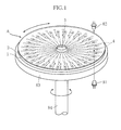
- the analyzing device A is roughly in the shape of a disc overall. As shown in Fig. 1 , the analyzing device comprises a base 1 and a cover 2 and is formed with an introducing chamber 3 and a plurality of microchannels 4.
- the base 1 is made of a transparent resin material such as polystyrene (PS), polymethyl methacrylate (PMMA) or polydimethylsiloxane (PDMS), and is in the shape of a disc.
- the base 1 is formed with indentations that constitute the introducing chamber 3 and the plurality of microchannels 4.
- the cover 2 is affixed to the base 1.
- the cover is in the form of a circular film or disc made of a transparent resin material such as polyethylene terephthalate (PET), polystyrene (PS), polymethyl methacrylate (PMMA) or polydimethylsiloxane (PDMS).
- the introducing chamber 3 is a site for introducing the specimen S such as blood using a dropper and the like, and is made of a through-hole formed in the cover 2 and a circular indentation formed in the base 1.
- a separating film (not shown) is provided in the introducing chamber 3. This separating film is interposed, for example, between the base 1 and the cover 2 to separate blood cell components in the blood.
- a porous substance such as a paper-like material, foam, woven fabric, non-woven fabric, knitted fabric, membrane filter, glass filter or gel-like material can be used for the separating film.
- the plurality of microchannels 4 are for transporting the specimen S introduced from the introducing chamber 3 by capillary phenomenon, and a portion thereof is used as the location of analyses using an optical technique.
- the plurality of microchannels 4 extends radially from the introducing chamber 3.
- each of the plurality of microchannels 4 includes an inflow opening 5, an analysis chamber 6 and a discharge portion 7.
- the inflow opening 5 is a site where the specimen S that has been introduced into the introducing chamber 3 flows into the analysis chamber 6.
- the width of the inflow opening 5 is about 0.1 mm and the depth is about 0.1 mm.
- the analysis chamber 6 is a site for carrying out analyses on the specimen S using an optical technique.
- the analysis chamber is circular, for example, and has a cross-sectional area which is larger than that of the portions located in front and behind thereof in the direction of flow.
- the analysis chamber 6 is an example of an enlarged portion defined in the present invention.
- the analysis chamber 6 is defined by a top surface 61, a bottom surface 62 and a pair of side surfaces 63a and 63b.
- the top surface 61 and the bottom surface 62 face each other, with a space therebetween, in the vertical direction of Fig. 4 that is perpendicular to the direction of flow.
- the paired side surfaces 63a and 63b face each other, with a space therebetween, in the width direction that is perpendicular to the vertical direction.
- the distance between the top surface 61 and the bottom surface 62, namely the depth of the analysis chamber 6, is about 0.1 mm.
- the radius of curvature of the pair of side surfaces 63a and 63b is about 0.6 mm, and from this, the approximate diameter of the analysis chamber 6 is about 1.2 mm.
- the analysis chamber 6 is coated with a reagent (not shown).
- This reagent is in the form of a dry solid that dissolves when the specimen S is supplied, and becomes colored as a result of reacting with a specific component in the specimen S.
- a plurality of types of reagents having different components or compositions, for example, is provided in the analyzing device A so as to enable measurement of a plurality of parameters.
- suitable locations other than the analysis chamber 6 may also be coated with a reagent.
- the discharge portion 7 is a site where the specimen S is discharged from the analysis chamber 6.
- the discharge portion includes a pair of discharge openings 71a and 71b, a separating portion 72, a pair of connecting channels 73a and 73b, a pair of retaining portions 74a and 74b, a pair of connecting channels 76a and 76b, and an open chamber 77.
- the paired discharge openings 71a and 71b are arranged side by side so as to be opposite to each other with respect to the inflow opening 5 as viewed in the direction of flow.
- the discharge opening 71a is connected to the side surface 63a, while the discharge opening 71b is connected to the side surface 63b.
- the separating portion 72 demarcates the pair of discharge openings 71a and 71b, and is tapered towards the upstream side in the direction of flow.
- the pair of connecting channels 73a and 73b are respectively connected to the pair of discharge openings 71a and 71b, and the width thereof is, for example, about 0.05 mm while the depth thereof is about 0.05 mm.
- the pair of retaining portions 74a and 74b are circular portions for retaining the discharged specimen S, and are respectively connected to the pair of connecting channels 73a and 73b.
- swelling members 75a and 75b are respectively provided in the retaining portions 74a and 74b.
- the swelling members 75a and 75b are made of a material in which the volume thereof swells by several to several hundred times as a result of absorbing the specimen S. Examples of such materials that may be used include Aquacork (Sumitomo Seika Chemicals), Wonder-Gel (Kao), Sanwet (Sanyo Chemical Industries) and Aqua Reserve GP (Nippon Synthetic Chemical Industry).
- the swelling members 75a and 75b are applied to a thickness so as to leave a space in the upper portions of the retaining portions 74a and 74b.
- the pair of retaining portions 74a and 74b are connected to the open chamber 77 via a pair of connecting channels 76a and 76b.
- the open chamber 77 is open to the atmosphere via a pathway not shown.
- the specimen S introduced from the introducing chamber 3 flows through the inflow opening 5 into the analysis chamber 6 by capillary phenomenon.
- the specimen S that has flowed in has a tendency to progress along the pair of side surfaces 63a and 63b. This is because the portion in the vicinity of each of the side surfaces 63a and 64b comprises a space surrounded on three sides by the top surface 61, the bottom surface 62 and the side surface 63a or 63b.
- the capillary force of such a space acts more strongly in comparison with a space surrounded on two sides only by the top surface 61 and the bottom surface 62 as in, for example, the central portion of the analysis chamber 6. Consequently, the specimen S proceeds more strongly.
- the side surface 63a and the side surface 63b are completely identical, and the side surfaces have various differences in nearly all cases.
- the boundary portion between the side surfaces 63a and 63b and the top surface 61 or the bottom surface 62 is formed to have an extremely minute round shape having a prescribed radius of curvature. Since there are limitations on the processing accuracy of such a boundary portion, a slight amount of error occurs in the round shape.
- variations occur in this processing as well depending on the particular location.
- the speed at which the specimen S proceeds along the side surface 63a is assumed to be relatively fast as shown in Fig. 6 .
- the specimen S proceeds along the side surface 63a while hardly proceeding at all along the side surface 63b.
- the specimen S proceeds further along the side surface 63a.
- the specimen S attempts to also proceed from the discharge opening 71a to the discharge opening 71b.
- the apex of the separating portion 72 constitutes a sharp angle, the apex demonstrates a considerably large resistance force on the specimen S when it attempts to cross it. Consequently, the specimen S does not proceed to the discharge opening 71b by crossing the separating portion 72.
- the specimen S proceeds from the discharge opening 71a to the connecting channel 73a. At this time as well, the specimen S hardly proceeds at all along the side surface 63b.
- the specimen S When the specimen S goes beyond the connecting channel 73a and reaches the retaining portion 74a, the specimen S is absorbed by the swelling member 75a. When this happens, the swelling member 75a that has become swollen completely blocks the retaining portion 74a as shown in Fig. 9 . As a result, the force that causes the specimen S to proceed through the discharge opening 71a, the connecting channel 73a and the retaining portion 74a no longer acts on the specimen S. Consequently, as shown in Fig. 10 , the force that causes the specimen S to move towards the discharge opening 71b, the connecting channel 73b and the retaining portion 74b acts on the specimen S. The specimen S then proceeds along the side surface 63b and reaches the discharge opening 71b as shown in Fig.
- the specimen S that has flowed into the analysis chamber 6 is discharged from both of the paired discharge openings 71a and 71b. Consequently, even if the specimen S reaches either the discharge opening 71a or 71b first, the remaining specimen S and air present in the analysis chamber 6 can be discharged from the other discharge opening 71a or 71b. Thus, a large air bubble can be prevented from remaining in the analysis chamber 6, thereby enabling analysis by an optical technique to be suitably carried out.
- the specimen S easily proceeds along the pair of side surfaces 63a and 63b where capillary force acts more strongly. Since the pair of discharge openings 71a and 71b are connected to these side surfaces 63a and 63b, the specimen S that has proceeded thereto can be reliably discharged from the discharge openings 71a and 71b. In addition, the specimen S that has proceeded to either of the pair of discharge openings 71a and 71b is stopped up by the separating portion 72. Consequently, there is little risk of both the discharge openings 71a and 71b being blocked by the specimen S that has proceeded along either of the pair of side surfaces 63a and 63b. This is suitable for avoiding the retention of an air bubble in the analysis chamber 6.
- the pair of retaining portions 74a and 74b are completely blocked by the swelling members 75a and 75b when the specimen S flows therein. Consequently, the specimen S that has been discharged from one of the paired discharge openings 71a and 71b can be prevented from flowing back into the analysis chamber 6 from the other one of the paired discharge openings 71a and 71b. This is suitable for preventing the retention of an air bubble in the analysis chamber 6. Furthermore, even if the swelling members 75a and 75b are not provided unlike the present embodiment, a considerable amount of specimens can still be retained in the retaining portions 74a and 74b. Consequently, the backflow of the specimen S from one of the paired discharge openings 71a and 71b into the other discharge opening can be delayed for a considerable amount of time, and the retention of an air bubble in the analysis chamber can also be avoided in this manner as well.
- Figs. 12 and 13 show another example of a retaining portion according to the present invention.
- the retaining portion 74c shown in the figure has a circular shape when viewed in plan, and as shown in Fig. 13 , has a top surface 741 and a bottom surface 742.
- the top surface 741 is a flat surface that does not have a level difference, and flush with the upper surfaces of connecting channels 73a and 76a.
- the bottom surface 742 as a whole faces the top surface 741 with a space therebetween, and is made up of an island portion 742a and a surrounding portion 742b. As shown in Fig.
- the island portion 742a is a portion that is located towards the center of the bottom surface 742, and in the present embodiment, has a circular shape when viewed in plan.
- the surrounding portion 742b surrounds the island portion 742a when viewed in plan, and in the present embodiment, has a doughnut shape when viewed in plan.
- the island portion 742a is relatively close to the top surface 741.
- the surrounding portion 742b is farther away from the top surface 741 than the island portion 742a is.
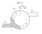
- the specimen S when the specimen S flows into the retaining portion 74c from the connecting channel 73a, the specimen S is retained between the surrounding portion 742b and the top surface 741, and does not enter the space between the island portion 742a and the top surface 741. As inflow of the specimen S proceeds further, the specimen S proceeds within the retaining portion 74c while being divided into two flows following the shape of the surrounding portion 742b. When air within the microchannel 4 attempts to flow with the inflow of the specimen S, the air is discharged to the connecting channel 76a after passing between the island portion 742a and the top surface 741. When the entire surrounding portion 742b is covered with the specimen S, the specimen S subsequently flows out to the connecting channel 76a.
- Fig. 15 shows still another example of a retaining portion according to the present invention.
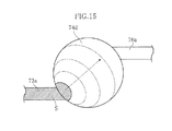
- the retaining portion 74d shown in the figure has a hydrophobic region in which the inner surface thereof has been subjected to hydrophobic treatment, and in the present embodiment, the top surface and the bottom surface constitute this hydrophobic region.
- resistance force by which the progression of the specimen is impaired is imparted by this hydrophobic region to the specimen S which is flown from the connecting channel 73a.
- the retaining portion 74b is able to delay outflow of the specimen S to the connecting channel 76a located on the downstream side thereof.
- Fig. 16 shows another example of a microchannel according to the present invention.
- the microchannel 4 shown in the figure includes three analysis chambers 6A, 6B and 6C connected to each other.
- the following provides an explanation of liquid transport using this microchannel 4.
- the specimen S is transported from the inflow opening 5A to the retaining portions 74a and 74b of a discharge portion 7A via the analysis chamber 6A using the same method as the liquid transport explained with reference to Figs. 5 to 11 .
- the specimen S reacts with, for example, a reagent applied in advance to the chamber.
- the retaining portions 74a and 74b of the present embodiment comprise relatively large-volume liquid tanks which do not contain the above-described swelling members 75a and 75b.
- retaining portions 74c or 74d may also be employed instead of the retaining portions 74a and 74b.
- a pressure reducing pump PA as pressure reducing means is connected to the open chamber 77A of the discharge portion 7A. After transport to the retaining portions 74a and 74b has been completed, the specimen S flows into the open chamber 77A when the internal pressure of the open chamber 77A is reduced by the pressure reducing pump PA.
- an open chamber 77B of the discharge portion 7B on the downstream side of the analysis chamber 6B is opened to the atmosphere.
- the specimen S is transported from the inflow opening 5B to the retaining portions 74a and 74b of the discharge portion 7B via the analysis chamber 6B in the same manner as the liquid transport explained with reference to Figs. 5 to 11 .
- the analysis chamber 6B the specimen is allowed to react, for example, with a different reagent from the reagent of the analysis chamber 6A.
- the analysis chamber 6B may be used to correct for the effects of the color of the specimen itself.
- a pressure reducing pump PB is connected to the open chamber 77B. The specimen S flows into the open chamber 77B when the internal pressure of the open chamber 77B is reduced by the pressure reducing pump PB.
- the specimen S is sent from the inflow opening 5C to the retaining portions 74a and 74b of the discharge portion 7C via the analysis chamber 6C.
- the specimen S is allowed to react, for example, with another different type of reagent.
- a pressure reducing pump PC is connected to the open chamber 77C. The specimen S flows into the open chamber 77C when the internal pressure of the open chamber 77C is reduced by the pressure reducing pump PC.
- processing in the plurality of analysis chambers 6A, 6B and 6C can be carried out consecutively. This is suitable for carrying out different types of tests on the same specimen in a short period of time.
- inflow of the specimen S into the open chamber 77C means that the specimen is ready to be further transported downstream from this chamber.
- different tests can also be carried out by adding different analysis chambers to the analysis chambers 6A, 6B and 6C and transporting the specimen S thereto.
- microchannel and analyzing device according to the present invention are not limited to the above-described embodiments.
- the specific structure of each portion of the microchannel and analyzing device according to the present invention may be varied in design in various ways.
- the analysis chamber 6 corresponding to an enlarged portion defined in the present invention is not limited to that having a circular shape, but rather is only required to have a shape that is able to suitably realize analysis by an optical technique while allowing transport of the specimen S by capillary phenomenon.
- the pair of discharge openings 71a and 71b is preferably demarcated by the separating portion 72, the present invention is not limited thereto.
- the pair of retaining portions 74a and 74b and the swelling members 75a and 75b provided therein are preferable for the purpose of preventing backflow of the specimen S, a configuration not provided therewith may also be employed provided that a configuration that makes it difficult for the specimen S to flow back through the microchannel 4 is provided on the downstream side of the discharge portion 7.
- the analyzing device A is an example of a device which carries out liquid transport using the microchannel 4, and may be a device which carries out analysis other than the analysis using an optical technique, for example.
- the liquid used for the specimen S is naturally not limited to blood.
- the microchannel according to the present invention is preferably used to analyze minute amounts of blood, it is not limited thereto, but rather can also be used in various applications in which a liquid is to be transported through an enlarged portion.
- the microchannel according to the present invention is not limited to that which uses capillary phenomenon as the driving force of liquid transport, but rather a structure may also be employed in which a liquid is transported by a relatively small pressure difference generated in front of and behind the microchannel in the direction of flow. This structure can also be expected to demonstrate the effect of inhibiting an air bubble from remaining in the enlarged portion, thereby enabling smooth liquid transport.
Landscapes
- Health & Medical Sciences (AREA)
- Chemical & Material Sciences (AREA)
- Life Sciences & Earth Sciences (AREA)
- General Health & Medical Sciences (AREA)
- Hematology (AREA)
- Analytical Chemistry (AREA)
- Engineering & Computer Science (AREA)
- Biomedical Technology (AREA)
- Physics & Mathematics (AREA)
- Chemical Kinetics & Catalysis (AREA)
- Clinical Laboratory Science (AREA)
- Dispersion Chemistry (AREA)
- General Physics & Mathematics (AREA)
- Pathology (AREA)
- Biochemistry (AREA)
- Immunology (AREA)
- Molecular Biology (AREA)
- Ecology (AREA)
- Medicinal Chemistry (AREA)
- Food Science & Technology (AREA)
- Urology & Nephrology (AREA)
- Biophysics (AREA)
- Automatic Analysis And Handling Materials Therefor (AREA)
Abstract
Description
- The present invention relates to a microchannel for transporting a liquid and an analyzing device.
- Reaction liquids obtained when a specimen and a reagent are allowed to react, for example, have been conventionally analyzed by methods using optical techniques. In the case of analyzing a specimen using such methods, an analyzing device is used that provides a reaction field. In the case of analyzing minute amounts of specimens, analyzing devices are used in which a microchannel is formed for transporting a liquid using capillary phenomenon (see, for example, Patent Document 1).
-
Fig. 17 shows an example of such a microchannel. The microchannel X shown in the figure includes aninflow opening 91, ananalysis chamber 92, adischarge opening 93 and anopen chamber 94, and is configured to allow a specimen S such as blood to be transported by capillary phenomenon. Theanalysis chamber 92 has a circular cross-section, and optically analyzes the concentration of a specific component in the specimen, for example, by allowing light to pass therethrough when filled with the specimen. Theanalysis chamber 92 is defined by a pair of mutuallyopposing side surfaces side surfaces open chamber 94 is connected to theanalysis chamber 92 via thedischarge opening 93. Theopen chamber 94 is open to the atmosphere by a pathway not shown. - Liquid is transported through the microchannel X in the following manner. First, a specimen S such as blood is introduced into the upstream side of the microchannel X. This specimen S is introduced by capillary phenomenon, and flows into the
analysis chamber 92 from theinflow opening 91 as shown inFig. 18 . The vicinities of theside surfaces side surface 92a or the pair of surfaces and theside surface 92b, and facilitate the action of capillary force on the specimen S to increase thrust. Consequently, the specimen S tends to proceed along theside surfaces - However, it is difficult to make the
side surfaces side surfaces side surfaces side surface 92a and the speed at which the specimen S proceeds along theside surface 92b. If this happens, the specimen S unevenly proceeds along theside surface 92a, for example, as shown inFig. 19 . As a result, the specimen S reaches the discharge opening 93 by passing over only theside surface 92a as shown inFig. 20 , thereby causing the discharge opening 93 to be blocked by the specimen S. As a result, an air bubble Bl ends up forming in the vicinity of theside surface 92b. Once this happens, even if analysis is carried out by an optical technique, light radiated onto theanalysis chamber 92 ends up passing through the air bubble Bl in addition to the specimen S. Thus, it becomes no longer possible to properly analyze a specific component of the specimen S. -
- Patent Document 1:
JP-A-2004-150804 - An object of the present invention, which is conceived under the above-described circumstances, is to provide a microchannel and an analyzing device that are able to properly transport a liquid.
- According to a first aspect of the present invention, there is provided a microchannel for transporting a liquid. The microchannel includes: an inflow portion located on the upstream side in the direction of flow; a discharge portion located on the downstream side in the direction of flow; and an enlarged portion located between the inflow portion and the discharge portion and having a cross-sectional area larger than those of the inflow portion and the discharge portion. The discharge portion includes a pair of discharge openings located opposite to each other with respect to the inflow portion as viewed in the direction of flow.
- In a preferred embodiment of the present invention, the liquid is transported using capillary phenomenon.
- In a preferred embodiment of the present invention, the discharge portion further includes a separating portion located between the pair of discharge openings and tapered towards the upstream side in the direction of flow.
- In a preferred embodiment of the present invention, the discharge portion further includes a retaining portion that is connected to at least one of the discharge openings on the downstream side in the direction of flow and has a cross-sectional area larger than the discharge opening.
- In a preferred embodiment of the present invention, the retaining portion is provided with a swelling member that inhibits the outflow of the liquid from the retaining portion to the downstream side by swelling upon absorbing the liquid.
- In a preferred embodiment of the present invention, the retaining portion has a top surface and a bottom surface that face each other with a space therebetween in a direction perpendicular to the direction of flow. The bottom surface includes an island portion located near the center when viewed in the direction in which the top surface and the bottom surface face each other with a space therebetween, and a surrounding portion that surrounds the island portion when viewed in the direction in which the top surface and the bottom surface face each other with a space therebetween, and is farther away from the top surface than the island portion is.
The retaining portion may include a hydrophobic region. - In a preferred embodiment of the present invention, the microchannel further includes: an additional enlarged portion located on the downstream side of the retaining portion in the direction of flow; an additional inflow portion for guiding the liquid from the retaining portion to the additional enlarged portion; and an additional discharge portion into which the liquid from the additional enlarged portion is discharged and includes a pair of additional discharge openings located opposite to each other with respect to the additional inflow portion as viewed in the direction of flow.
- In a preferred embodiment of the present invention, an open chamber that can be open to the atmosphere is provided between the retaining portion and the additional inflow portion.
- In a preferred embodiment of the present invention, the open chamber is connected to a pressure reducer capable of reducing pressure within the open chamber.
- An analyzing device provided according to a second aspect of the present invention includes the microchannel as set forth in the first aspect of the present invention. In the analyzing device, the enlarged portion is used as an analysis field.
- Other features and advantages of the present invention will be made clearer from the following detailed description provided with reference to the attached drawings.
-
-
Fig. 1 is a perspective view showing an example of an analyzing device according to the present invention; -
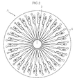
Fig. 2 is a plan view showing the principal parts of the analyzing device shown inFig. 1 ; -
Fig. 3 is a plan view showing the principal parts of an example of a microchannel according to the present invention; -
Fig. 4 is a sectional view showing principal parts taken along line IV-IV inFig. 3 ; -
Fig. 5 is a plan view of principal parts depicting liquid transport in the microchannel shown inFig. 3 ; -
Fig. 6 is a plan view of principal parts depicting liquid transport in the microchannel shown inFig. 3 ; -
Fig. 7 is a plan view of principal parts depicting liquid transport in the microchannel shown inFig. 3 ; -
Fig. 8 is a plan view of principal parts depicting liquid transport in the microchannel shown inFig. 3 ; -
Fig. 9 is a sectional view showing principal parts taken along line IX-IX inFig. 8 ; -
Fig. 10 is a plan view of principal parts depicting liquid transport in the microchannel shown inFig. 3 ; -
Fig. 11 is a plan view of principal parts depicting liquid transport in the microchannel shown inFig. 3 ; -
Fig. 12 is a plan view showing the principal parts of another example of a retaining portion; -
Fig. 13 is a sectional view showing principal parts taken along line XIII-XIII inFig. 12 ; -
Fig. 14 is a plan view of principal parts depicting the flow of a liquid in the retaining portion shown inFig. 12 ; -
Fig. 15 is a plan view of the principal parts of still another example of a retaining portion; -
Fig. 16 is a plan view of the principal parts of another example of a microchannel according to the present invention; -
Fig. 17 is a plan view showing the principal parts of an example of a conventional microchannel; -
Fig. 18 is a plan view of principal parts showing liquid transport in the microchannel shown inFig. 12 ; -
Fig. 19 is a plan view of principal parts showing liquid transport in the microchannel shown inFig. 12 ; and, -
Fig. 20 is a plan view of principal parts showing liquid transport in the microchannel shown inFig. 12 . - Preferred embodiments of the present invention are described below with reference to the drawings.
-
Figs. 1 and2 show an example of an analyzing device according to the present invention. An analyzing device A of the present embodiment is for carrying out analyses relating to a specific component by an optical technique on a specimen S such as blood. The analyzing device A is configured to be installed in an analyzer (not shown). InFig. 2 , acover 2 to be described later is omitted to facilitate understanding. The analyzing device A is supported by asupport stand 83 provided in the analyzer. A rotatingshaft 84 is connected to thesupport stand 83, making the analyzing device A rotatable. Alight emitting module 81, which includes an LED chip, for example, serves as a light source that emits light for optical analyses. Alight receiving module 82, which includes an silicon photodiode, for example, receives light from thelight emitting module 81 that has passed through the analyzing device A. The analyzer is configured to analyze a specific component of the specimen S according to the light receiving state of thelight receiving module 82. - The analyzing device A is roughly in the shape of a disc overall. As shown in
Fig. 1 , the analyzing device comprises abase 1 and acover 2 and is formed with an introducingchamber 3 and a plurality ofmicrochannels 4. - The
base 1 is made of a transparent resin material such as polystyrene (PS), polymethyl methacrylate (PMMA) or polydimethylsiloxane (PDMS), and is in the shape of a disc. Thebase 1 is formed with indentations that constitute the introducingchamber 3 and the plurality ofmicrochannels 4. Thecover 2 is affixed to thebase 1. The cover is in the form of a circular film or disc made of a transparent resin material such as polyethylene terephthalate (PET), polystyrene (PS), polymethyl methacrylate (PMMA) or polydimethylsiloxane (PDMS). - The introducing
chamber 3 is a site for introducing the specimen S such as blood using a dropper and the like, and is made of a through-hole formed in thecover 2 and a circular indentation formed in thebase 1. A separating film (not shown) is provided in the introducingchamber 3. This separating film is interposed, for example, between thebase 1 and thecover 2 to separate blood cell components in the blood. A porous substance such as a paper-like material, foam, woven fabric, non-woven fabric, knitted fabric, membrane filter, glass filter or gel-like material can be used for the separating film. - The plurality of
microchannels 4 are for transporting the specimen S introduced from the introducingchamber 3 by capillary phenomenon, and a portion thereof is used as the location of analyses using an optical technique. In the present embodiment, the plurality ofmicrochannels 4 extends radially from the introducingchamber 3. As shown inFig. 3 , each of the plurality ofmicrochannels 4 includes aninflow opening 5, ananalysis chamber 6 and adischarge portion 7. - The
inflow opening 5 is a site where the specimen S that has been introduced into the introducingchamber 3 flows into theanalysis chamber 6. In the present embodiment, the width of theinflow opening 5 is about 0.1 mm and the depth is about 0.1 mm. - The
analysis chamber 6 is a site for carrying out analyses on the specimen S using an optical technique. The analysis chamber is circular, for example, and has a cross-sectional area which is larger than that of the portions located in front and behind thereof in the direction of flow. Theanalysis chamber 6 is an example of an enlarged portion defined in the present invention. As shown inFigs. 3 and 4 , theanalysis chamber 6 is defined by atop surface 61, abottom surface 62 and a pair ofside surfaces top surface 61 and thebottom surface 62 face each other, with a space therebetween, in the vertical direction ofFig. 4 that is perpendicular to the direction of flow. The pairedside surfaces top surface 61 and thebottom surface 62, namely the depth of theanalysis chamber 6, is about 0.1 mm. The radius of curvature of the pair ofside surfaces analysis chamber 6 is about 1.2 mm. - In the present embodiment, the
analysis chamber 6 is coated with a reagent (not shown). This reagent is in the form of a dry solid that dissolves when the specimen S is supplied, and becomes colored as a result of reacting with a specific component in the specimen S. A plurality of types of reagents having different components or compositions, for example, is provided in the analyzing device A so as to enable measurement of a plurality of parameters. However, it is not always necessary to provide the reagents in all of theanalysis chambers 6, and coating of the reagent may be omitted for theanalysis chambers 6 that are used, for example, to correct for the effects of the color of the specimen itself. In addition, suitable locations other than theanalysis chamber 6 may also be coated with a reagent. - The
discharge portion 7 is a site where the specimen S is discharged from theanalysis chamber 6. The discharge portion includes a pair ofdischarge openings portion 72, a pair of connectingchannels portions channels open chamber 77. The paireddischarge openings inflow opening 5 as viewed in the direction of flow. Thedischarge opening 71a is connected to theside surface 63a, while thedischarge opening 71b is connected to theside surface 63b. The separatingportion 72 demarcates the pair ofdischarge openings channels discharge openings - The pair of retaining
portions channels members portions members members portions portions open chamber 77 via a pair of connectingchannels open chamber 77 is open to the atmosphere via a pathway not shown. - Next, liquid transport in the
microchannels 4 is described with reference toFigs. 5 to 11 . - As shown in
Fig. 5 , the specimen S introduced from the introducingchamber 3 flows through theinflow opening 5 into theanalysis chamber 6 by capillary phenomenon. The specimen S that has flowed in has a tendency to progress along the pair ofside surfaces top surface 61, thebottom surface 62 and theside surface top surface 61 and thebottom surface 62 as in, for example, the central portion of theanalysis chamber 6. Consequently, the specimen S proceeds more strongly. - However, it is rare for the
side surface 63a and theside surface 63b to be completely identical, and the side surfaces have various differences in nearly all cases. For example, the boundary portion between the side surfaces 63a and 63b and thetop surface 61 or thebottom surface 62 is formed to have an extremely minute round shape having a prescribed radius of curvature. Since there are limitations on the processing accuracy of such a boundary portion, a slight amount of error occurs in the round shape. Alternatively, in the case of carrying out surface treatment on e.g. thetop surface 61 andbottom surface 62 to make capillary force uniform, variations occur in this processing as well depending on the particular location. In such circumstances, a considerable difference ends up occurring between the speed at which the specimen S proceeds along theside surface 63a and the speed at which the specimen S proceeds along theside surface 63b. In the present embodiment, the speed at which the specimen S proceeds along theside surface 63a is assumed to be relatively fast as shown inFig. 6 . In such a case, as shown inFig. 7 , the specimen S proceeds along theside surface 63a while hardly proceeding at all along theside surface 63b. - As shown in
Fig. 8 , as the specimen S proceeds further along theside surface 63a, the specimen S reaches thedischarge opening 71a. At this time, the specimen S attempts to also proceed from thedischarge opening 71a to thedischarge opening 71b. However, since the apex of the separatingportion 72 constitutes a sharp angle, the apex demonstrates a considerably large resistance force on the specimen S when it attempts to cross it. Consequently, the specimen S does not proceed to thedischarge opening 71b by crossing the separatingportion 72. Thus, the specimen S proceeds from thedischarge opening 71a to the connectingchannel 73a. At this time as well, the specimen S hardly proceeds at all along theside surface 63b. - When the specimen S goes beyond the connecting
channel 73a and reaches the retainingportion 74a, the specimen S is absorbed by the swellingmember 75a. When this happens, the swellingmember 75a that has become swollen completely blocks the retainingportion 74a as shown inFig. 9 . As a result, the force that causes the specimen S to proceed through thedischarge opening 71a, the connectingchannel 73a and the retainingportion 74a no longer acts on the specimen S. Consequently, as shown inFig. 10 , the force that causes the specimen S to move towards thedischarge opening 71b, the connectingchannel 73b and the retainingportion 74b acts on the specimen S. The specimen S then proceeds along theside surface 63b and reaches thedischarge opening 71b as shown inFig. 11 . When the specimen S reaches the retainingportion 74b via the connectingchannel 73b, the retainingportion 74b is blocked by swelling of the swellingmember 75b. As a result of the above, transport of the specimen S in themicrochannel 4 shown ends. Subsequently, analysis is carried out by an optical technique by radiating light from thelight emitting module 81 onto theanalysis chamber 6 that is filled with the specimen S. - Next, the advantages of the analyzing device A and the
microchannels 4 are described. - According to the present embodiment, the specimen S that has flowed into the
analysis chamber 6 is discharged from both of the paireddischarge openings discharge opening analysis chamber 6 can be discharged from the other discharge opening 71a or 71b. Thus, a large air bubble can be prevented from remaining in theanalysis chamber 6, thereby enabling analysis by an optical technique to be suitably carried out. - The specimen S easily proceeds along the pair of
side surfaces discharge openings side surfaces discharge openings discharge openings portion 72. Consequently, there is little risk of both thedischarge openings side surfaces analysis chamber 6. - The pair of retaining
portions members discharge openings analysis chamber 6 from the other one of the paireddischarge openings analysis chamber 6. Furthermore, even if the swellingmembers portions discharge openings -
Figs. 12 and13 show another example of a retaining portion according to the present invention. The retainingportion 74c shown in the figure has a circular shape when viewed in plan, and as shown inFig. 13 , has atop surface 741 and abottom surface 742. Thetop surface 741 is a flat surface that does not have a level difference, and flush with the upper surfaces of connectingchannels bottom surface 742 as a whole faces thetop surface 741 with a space therebetween, and is made up of anisland portion 742a and a surroundingportion 742b. As shown inFig. 12 , theisland portion 742a is a portion that is located towards the center of thebottom surface 742, and in the present embodiment, has a circular shape when viewed in plan. The surroundingportion 742b surrounds theisland portion 742a when viewed in plan, and in the present embodiment, has a doughnut shape when viewed in plan. As shown inFig. 13 , theisland portion 742a is relatively close to thetop surface 741. On the other hand, the surroundingportion 742b is farther away from thetop surface 741 than theisland portion 742a is. - As shown in
Fig. 14 , when the specimen S flows into the retainingportion 74c from the connectingchannel 73a, the specimen S is retained between the surroundingportion 742b and thetop surface 741, and does not enter the space between theisland portion 742a and thetop surface 741. As inflow of the specimen S proceeds further, the specimen S proceeds within the retainingportion 74c while being divided into two flows following the shape of the surroundingportion 742b. When air within themicrochannel 4 attempts to flow with the inflow of the specimen S, the air is discharged to the connectingchannel 76a after passing between theisland portion 742a and thetop surface 741. When the entire surroundingportion 742b is covered with the specimen S, the specimen S subsequently flows out to the connectingchannel 76a. With this arrangement as well, backflow of the specimen S from one of the paireddischarge openings Fig. 3 to the other discharge opening can be delayed for a considerable amount of time, thereby making it possible to avoid retention of air bubbles. -
Fig. 15 shows still another example of a retaining portion according to the present invention. The retainingportion 74d shown in the figure has a hydrophobic region in which the inner surface thereof has been subjected to hydrophobic treatment, and in the present embodiment, the top surface and the bottom surface constitute this hydrophobic region. In this case, resistance force by which the progression of the specimen is impaired is imparted by this hydrophobic region to the specimen S which is flown from the connectingchannel 73a. As a result, the retainingportion 74b is able to delay outflow of the specimen S to the connectingchannel 76a located on the downstream side thereof. With this arrangement as well, backflow of the specimen S from one of the paireddischarge openings Fig. 3 to the other discharge opening can be delayed for a considerable amount of time, thereby making it possible to avoid retention of air bubbles. -
Fig. 16 shows another example of a microchannel according to the present invention. Themicrochannel 4 shown in the figure includes threeanalysis chambers microchannel 4. First, the specimen S is transported from theinflow opening 5A to the retainingportions discharge portion 7A via theanalysis chamber 6A using the same method as the liquid transport explained with reference toFigs. 5 to 11 . In theanalysis chamber 6A, the specimen S reacts with, for example, a reagent applied in advance to the chamber. The retainingportions swelling members retaining portions portions open chamber 77A of thedischarge portion 7A. After transport to the retainingportions open chamber 77A when the internal pressure of theopen chamber 77A is reduced by the pressure reducing pump PA. - Next, an
open chamber 77B of thedischarge portion 7B on the downstream side of theanalysis chamber 6B is opened to the atmosphere. When this happens, the specimen S is transported from theinflow opening 5B to the retainingportions discharge portion 7B via theanalysis chamber 6B in the same manner as the liquid transport explained with reference toFigs. 5 to 11 . In theanalysis chamber 6B, the specimen is allowed to react, for example, with a different reagent from the reagent of theanalysis chamber 6A. Alternatively, in the case where theanalysis chamber 6B is of a configuration in which a reagent is not applied, theanalysis chamber 6B may be used to correct for the effects of the color of the specimen itself. A pressure reducing pump PB is connected to theopen chamber 77B. The specimen S flows into theopen chamber 77B when the internal pressure of theopen chamber 77B is reduced by the pressure reducing pump PB. - Moreover, when an
open chamber 77C of adischarge portion 7C on the downstream side of theanalysis chamber 6C is opened to the atmosphere, the specimen S is sent from the inflow opening 5C to the retainingportions discharge portion 7C via theanalysis chamber 6C. In theanalysis chamber 6C, the specimen S is allowed to react, for example, with another different type of reagent. A pressure reducing pump PC is connected to theopen chamber 77C. The specimen S flows into theopen chamber 77C when the internal pressure of theopen chamber 77C is reduced by the pressure reducing pump PC. - Thus, according to the present embodiment, processing in the plurality of
analysis chambers open chamber 77C means that the specimen is ready to be further transported downstream from this chamber. Thus, different tests can also be carried out by adding different analysis chambers to theanalysis chambers - The microchannel and analyzing device according to the present invention are not limited to the above-described embodiments. The specific structure of each portion of the microchannel and analyzing device according to the present invention may be varied in design in various ways.
- The
analysis chamber 6 corresponding to an enlarged portion defined in the present invention is not limited to that having a circular shape, but rather is only required to have a shape that is able to suitably realize analysis by an optical technique while allowing transport of the specimen S by capillary phenomenon. Although the pair ofdischarge openings portion 72, the present invention is not limited thereto. Although the pair of retainingportions members microchannel 4 is provided on the downstream side of thedischarge portion 7. - The analyzing device A is an example of a device which carries out liquid transport using the
microchannel 4, and may be a device which carries out analysis other than the analysis using an optical technique, for example. In addition, the liquid used for the specimen S is naturally not limited to blood. Although the microchannel according to the present invention is preferably used to analyze minute amounts of blood, it is not limited thereto, but rather can also be used in various applications in which a liquid is to be transported through an enlarged portion. Moreover, the microchannel according to the present invention is not limited to that which uses capillary phenomenon as the driving force of liquid transport, but rather a structure may also be employed in which a liquid is transported by a relatively small pressure difference generated in front of and behind the microchannel in the direction of flow. This structure can also be expected to demonstrate the effect of inhibiting an air bubble from remaining in the enlarged portion, thereby enabling smooth liquid transport.
Claims (11)
- A microchannel for transporting a liquid, comprising:an inflow portion located on an upstream side in a direction of flow;a discharge portion located on a downstream side in the direction of flow; andan enlarged portion located between the inflow portion and the discharge portion and having a cross-sectional area larger than those of the inflow portion and the discharge portion;wherein the discharge portion includes a pair of discharge openings located opposite to each other with respect to the inflow portion as viewed in the direction of flow.
- The microchannel according to claim 1, wherein the liquid is transported using capillary phenomenon.
- The microchannel according to claim 1, wherein the discharge portion further includes a separating portion located between the discharge openings and tapered towards the upstream side in the direction of flow.
- The microchannel according to claim 1, wherein the discharge portion further includes a retaining portion that is connected to at least one of the discharge openings on the downstream side in the direction of flow and has a cross-sectional area larger than that of the discharge opening.
- The microchannel according to claim 4, wherein the retaining portion is provided with a swelling member that inhibits outflow of the liquid from the retaining portion to the downstream side by swelling upon absorbing the liquid.
- The microchannel according to claim 4, wherein the retaining portion includes a top surface and a bottom surface that face each other with a space therebetween in a direction perpendicular to the direction of flow, and
the bottom surface includes an island portion located near the center when viewed in a direction in which the top surface and the bottom surface face each other with a space therebetween, and a surrounding portion that surrounds the island portion when viewed in the direction in which the top surface and the bottom surface face each other with a space therebetween, and is farther away from the top surface than the island portion is. - The microchannel according to claim 4, wherein the retaining portion includes a hydrophobic region.
- The microchannel according to claim 1, further comprising:an additional enlarged portion located on the downstream side of the retaining portion in the direction of flow;an additional inflow portion for guiding the liquid from the retaining portion to the additional enlarged portion; andan additional discharge portion into which the liquid from the additional enlarged portion is discharged and includes a pair of additional discharge openings located opposite to each other with respect to the additional inflow portion as viewed in the direction of flow.
- The microchannel according to claim 7, wherein an open chamber that can be open to the atmosphere is provided between the retaining portion and the additional inflow portion.
- The microchannel according to claim 8, wherein the open chamber is connected to a pressure reducer capable of reducing pressure within the open chamber.
- An analyzing device, comprising the microchannel as set forth in claim 1, wherein the enlarged portion is used as an analysis field.
Applications Claiming Priority (2)
| Application Number | Priority Date | Filing Date | Title |
|---|---|---|---|
| JP2008115481 | 2008-04-25 | ||
| PCT/JP2009/056503 WO2009130976A1 (en) | 2008-04-25 | 2009-03-30 | Microchannel and analyzing device |
Publications (3)
| Publication Number | Publication Date |
|---|---|
| EP2270515A1 true EP2270515A1 (en) | 2011-01-05 |
| EP2270515A4 EP2270515A4 (en) | 2016-10-05 |
| EP2270515B1 EP2270515B1 (en) | 2019-05-08 |
Family
ID=41216714
Family Applications (1)
| Application Number | Title | Priority Date | Filing Date |
|---|---|---|---|
| EP09733832.1A Active EP2270515B1 (en) | 2008-04-25 | 2009-03-30 | Microchannel and analyzing device |
Country Status (5)
| Country | Link |
|---|---|
| US (1) | US8398937B2 (en) |
| EP (1) | EP2270515B1 (en) |
| JP (1) | JP5255628B2 (en) |
| CN (1) | CN102016598B (en) |
| WO (1) | WO2009130976A1 (en) |
Cited By (1)
| Publication number | Priority date | Publication date | Assignee | Title |
|---|---|---|---|---|
| TWI385030B (en) * | 2010-12-22 | 2013-02-11 | Univ Nat Chiao Tung | Microfluidic system and gas discharge method and gas reaction method thereof |
Families Citing this family (6)
| Publication number | Priority date | Publication date | Assignee | Title |
|---|---|---|---|---|
| EP2213364A1 (en) * | 2009-01-30 | 2010-08-04 | Albert-Ludwigs-Universität Freiburg | Phase guide patterns for liquid manipulation |
| JP5250574B2 (en) * | 2010-02-10 | 2013-07-31 | 富士フイルム株式会社 | Microchannel device |
| EP2896457B1 (en) * | 2014-01-15 | 2017-08-23 | IMEC vzw | Microstructured micropillar arrays for controllable filling of a capillary pump |
| JP2016217929A (en) * | 2015-05-22 | 2016-12-22 | セイコーエプソン株式会社 | Sensor gel and sensor |
| US9757728B2 (en) * | 2016-01-26 | 2017-09-12 | Lidong Qin | Microfluidic aliquoting for single-cell isolation |
| WO2020066609A1 (en) * | 2018-09-28 | 2020-04-02 | ウシオ電機株式会社 | Cell culture chip |
Family Cites Families (10)
| Publication number | Priority date | Publication date | Assignee | Title |
|---|---|---|---|---|
| US4756884A (en) | 1985-08-05 | 1988-07-12 | Biotrack, Inc. | Capillary flow device |
| US6637463B1 (en) * | 1998-10-13 | 2003-10-28 | Biomicro Systems, Inc. | Multi-channel microfluidic system design with balanced fluid flow distribution |
| US8231845B2 (en) * | 2000-10-25 | 2012-07-31 | Steag Microparts | Structures for uniform capillary flow |
| WO2003025547A1 (en) * | 2001-09-21 | 2003-03-27 | Biomedlab Corporation | Method and device for screening analytes using surface plasmon resonance |
| JP4262466B2 (en) | 2002-10-28 | 2009-05-13 | アークレイ株式会社 | Analysis tool and analyzer |
| EP1525916A1 (en) | 2003-10-23 | 2005-04-27 | F. Hoffmann-La Roche Ag | Flow triggering device |
| WO2006098370A1 (en) * | 2005-03-16 | 2006-09-21 | Nec Corporation | Delay circuit with mechanism for adjusting effective passing time of channel, microchip, and method for fabricating the same |
| US20090220948A1 (en) * | 2005-03-16 | 2009-09-03 | Attogenix Biosystems Pte Ltd. | Methods and Device for Transmitting, Enclosing and Analysing Fluid Samples |
| US7754151B2 (en) | 2005-04-04 | 2010-07-13 | Panasonic Corporation | Liquid homogenizer and analyzer employing the same |
| JPWO2007013562A1 (en) * | 2005-07-29 | 2009-02-12 | アークレイ株式会社 | Analysis tool |
-
2009
- 2009-03-30 US US12/988,602 patent/US8398937B2/en active Active
- 2009-03-30 EP EP09733832.1A patent/EP2270515B1/en active Active
- 2009-03-30 JP JP2010509125A patent/JP5255628B2/en active Active
- 2009-03-30 WO PCT/JP2009/056503 patent/WO2009130976A1/en not_active Ceased
- 2009-03-30 CN CN2009801144765A patent/CN102016598B/en active Active
Non-Patent Citations (1)
| Title |
|---|
| See references of WO2009130976A1 * |
Cited By (1)
| Publication number | Priority date | Publication date | Assignee | Title |
|---|---|---|---|---|
| TWI385030B (en) * | 2010-12-22 | 2013-02-11 | Univ Nat Chiao Tung | Microfluidic system and gas discharge method and gas reaction method thereof |
Also Published As
| Publication number | Publication date |
|---|---|
| JPWO2009130976A1 (en) | 2011-08-18 |
| EP2270515A4 (en) | 2016-10-05 |
| CN102016598B (en) | 2013-10-30 |
| CN102016598A (en) | 2011-04-13 |
| EP2270515B1 (en) | 2019-05-08 |
| US8398937B2 (en) | 2013-03-19 |
| JP5255628B2 (en) | 2013-08-07 |
| US20110038766A1 (en) | 2011-02-17 |
| WO2009130976A1 (en) | 2009-10-29 |
Similar Documents
| Publication | Publication Date | Title |
|---|---|---|
| US10159978B2 (en) | Flow control in microfluidic systems | |
| EP2270515B1 (en) | Microchannel and analyzing device | |
| US11181522B2 (en) | Analytical cartridge with fluid flow control | |
| ES2859481T3 (en) | Mixing and dispensing fluids in microfluidic systems | |
| JP4141494B2 (en) | Microanalytical measuring apparatus and microanalytical measuring method using the same | |
| US8821813B2 (en) | Liquid-feeding chip and analysis method | |
| US20040265172A1 (en) | Method and apparatus for entry and storage of specimens into a microfluidic device | |
| US20080257754A1 (en) | Method and apparatus for entry of specimens into a microfluidic device | |
| US20210154662A1 (en) | Apparatus and method for directing a liquid through a porous medium | |
| JP2005230816A (en) | Platform microstructured to process liquid and using method of the same | |
| ES2863533T3 (en) | Fluidic system for testing | |
| JP4619224B2 (en) | Rotational analysis device | |
| US20250147016A1 (en) | Chip-based optical detection system | |
| CN101623660A (en) | Analysis spraying canister having liquid stream control | |
| JP2009287971A (en) | Microchip | |
| JP5177533B2 (en) | Microchip | |
| JP2006053090A (en) | Inspection plate and inspection method using it | |
| US7586612B2 (en) | Photometric analysis of biological samples using in-plane detection | |
| EP1912074B1 (en) | Analyzer | |
| JP7807822B2 (en) | Assay Device |
Legal Events
| Date | Code | Title | Description |
|---|---|---|---|
| PUAI | Public reference made under article 153(3) epc to a published international application that has entered the european phase |
Free format text: ORIGINAL CODE: 0009012 |
|
| 17P | Request for examination filed |
Effective date: 20101028 |
|
| AK | Designated contracting states |
Kind code of ref document: A1 Designated state(s): AT BE BG CH CY CZ DE DK EE ES FI FR GB GR HR HU IE IS IT LI LT LU LV MC MK MT NL NO PL PT RO SE SI SK TR |
|
| AX | Request for extension of the european patent |
Extension state: AL BA RS |
|
| DAX | Request for extension of the european patent (deleted) | ||
| RA4 | Supplementary search report drawn up and despatched (corrected) |
Effective date: 20160907 |
|
| RIC1 | Information provided on ipc code assigned before grant |
Ipc: G01N 35/00 20060101ALI20160901BHEP Ipc: G01N 37/00 20060101ALI20160901BHEP Ipc: G01N 35/08 20060101AFI20160901BHEP |
|
| STAA | Information on the status of an ep patent application or granted ep patent |
Free format text: STATUS: EXAMINATION IS IN PROGRESS |
|
| 17Q | First examination report despatched |
Effective date: 20180528 |
|
| REG | Reference to a national code |
Ref country code: DE Ref legal event code: R079 Ref document number: 602009058246 Country of ref document: DE Free format text: PREVIOUS MAIN CLASS: G01N0035080000 Ipc: G01N0033490000 |
|
| RIC1 | Information provided on ipc code assigned before grant |
Ipc: B01L 3/00 20060101ALI20181010BHEP Ipc: G01N 35/00 20060101ALI20181010BHEP Ipc: G01N 33/49 20060101AFI20181010BHEP |
|
| GRAP | Despatch of communication of intention to grant a patent |
Free format text: ORIGINAL CODE: EPIDOSNIGR1 |
|
| STAA | Information on the status of an ep patent application or granted ep patent |
Free format text: STATUS: GRANT OF PATENT IS INTENDED |
|
| INTG | Intention to grant announced |
Effective date: 20181205 |
|
| GRAS | Grant fee paid |
Free format text: ORIGINAL CODE: EPIDOSNIGR3 |
|
| GRAA | (expected) grant |
Free format text: ORIGINAL CODE: 0009210 |
|
| STAA | Information on the status of an ep patent application or granted ep patent |
Free format text: STATUS: THE PATENT HAS BEEN GRANTED |
|
| AK | Designated contracting states |
Kind code of ref document: B1 Designated state(s): AT BE BG CH CY CZ DE DK EE ES FI FR GB GR HR HU IE IS IT LI LT LU LV MC MK MT NL NO PL PT RO SE SI SK TR |
|
| REG | Reference to a national code |
Ref country code: GB Ref legal event code: FG4D |
|
| REG | Reference to a national code |
Ref country code: CH Ref legal event code: EP Ref country code: AT Ref legal event code: REF Ref document number: 1130975 Country of ref document: AT Kind code of ref document: T Effective date: 20190515 |
|
| REG | Reference to a national code |
Ref country code: DE Ref legal event code: R096 Ref document number: 602009058246 Country of ref document: DE Ref country code: IE Ref legal event code: FG4D |
|
| REG | Reference to a national code |
Ref country code: NL Ref legal event code: MP Effective date: 20190508 |
|
| REG | Reference to a national code |
Ref country code: LT Ref legal event code: MG4D |
|
| PG25 | Lapsed in a contracting state [announced via postgrant information from national office to epo] |
Ref country code: NL Free format text: LAPSE BECAUSE OF FAILURE TO SUBMIT A TRANSLATION OF THE DESCRIPTION OR TO PAY THE FEE WITHIN THE PRESCRIBED TIME-LIMIT Effective date: 20190508 Ref country code: SE Free format text: LAPSE BECAUSE OF FAILURE TO SUBMIT A TRANSLATION OF THE DESCRIPTION OR TO PAY THE FEE WITHIN THE PRESCRIBED TIME-LIMIT Effective date: 20190508 Ref country code: LT Free format text: LAPSE BECAUSE OF FAILURE TO SUBMIT A TRANSLATION OF THE DESCRIPTION OR TO PAY THE FEE WITHIN THE PRESCRIBED TIME-LIMIT Effective date: 20190508 Ref country code: FI Free format text: LAPSE BECAUSE OF FAILURE TO SUBMIT A TRANSLATION OF THE DESCRIPTION OR TO PAY THE FEE WITHIN THE PRESCRIBED TIME-LIMIT Effective date: 20190508 Ref country code: PT Free format text: LAPSE BECAUSE OF FAILURE TO SUBMIT A TRANSLATION OF THE DESCRIPTION OR TO PAY THE FEE WITHIN THE PRESCRIBED TIME-LIMIT Effective date: 20190908 Ref country code: ES Free format text: LAPSE BECAUSE OF FAILURE TO SUBMIT A TRANSLATION OF THE DESCRIPTION OR TO PAY THE FEE WITHIN THE PRESCRIBED TIME-LIMIT Effective date: 20190508 Ref country code: NO Free format text: LAPSE BECAUSE OF FAILURE TO SUBMIT A TRANSLATION OF THE DESCRIPTION OR TO PAY THE FEE WITHIN THE PRESCRIBED TIME-LIMIT Effective date: 20190808 Ref country code: HR Free format text: LAPSE BECAUSE OF FAILURE TO SUBMIT A TRANSLATION OF THE DESCRIPTION OR TO PAY THE FEE WITHIN THE PRESCRIBED TIME-LIMIT Effective date: 20190508 |
|
| PG25 | Lapsed in a contracting state [announced via postgrant information from national office to epo] |
Ref country code: GR Free format text: LAPSE BECAUSE OF FAILURE TO SUBMIT A TRANSLATION OF THE DESCRIPTION OR TO PAY THE FEE WITHIN THE PRESCRIBED TIME-LIMIT Effective date: 20190809 Ref country code: BG Free format text: LAPSE BECAUSE OF FAILURE TO SUBMIT A TRANSLATION OF THE DESCRIPTION OR TO PAY THE FEE WITHIN THE PRESCRIBED TIME-LIMIT Effective date: 20190808 Ref country code: LV Free format text: LAPSE BECAUSE OF FAILURE TO SUBMIT A TRANSLATION OF THE DESCRIPTION OR TO PAY THE FEE WITHIN THE PRESCRIBED TIME-LIMIT Effective date: 20190508 |
|
| REG | Reference to a national code |
Ref country code: AT Ref legal event code: MK05 Ref document number: 1130975 Country of ref document: AT Kind code of ref document: T Effective date: 20190508 |
|
| PG25 | Lapsed in a contracting state [announced via postgrant information from national office to epo] |
Ref country code: EE Free format text: LAPSE BECAUSE OF FAILURE TO SUBMIT A TRANSLATION OF THE DESCRIPTION OR TO PAY THE FEE WITHIN THE PRESCRIBED TIME-LIMIT Effective date: 20190508 Ref country code: AT Free format text: LAPSE BECAUSE OF FAILURE TO SUBMIT A TRANSLATION OF THE DESCRIPTION OR TO PAY THE FEE WITHIN THE PRESCRIBED TIME-LIMIT Effective date: 20190508 Ref country code: DK Free format text: LAPSE BECAUSE OF FAILURE TO SUBMIT A TRANSLATION OF THE DESCRIPTION OR TO PAY THE FEE WITHIN THE PRESCRIBED TIME-LIMIT Effective date: 20190508 Ref country code: RO Free format text: LAPSE BECAUSE OF FAILURE TO SUBMIT A TRANSLATION OF THE DESCRIPTION OR TO PAY THE FEE WITHIN THE PRESCRIBED TIME-LIMIT Effective date: 20190508 Ref country code: CZ Free format text: LAPSE BECAUSE OF FAILURE TO SUBMIT A TRANSLATION OF THE DESCRIPTION OR TO PAY THE FEE WITHIN THE PRESCRIBED TIME-LIMIT Effective date: 20190508 Ref country code: SK Free format text: LAPSE BECAUSE OF FAILURE TO SUBMIT A TRANSLATION OF THE DESCRIPTION OR TO PAY THE FEE WITHIN THE PRESCRIBED TIME-LIMIT Effective date: 20190508 |
|
| REG | Reference to a national code |
Ref country code: DE Ref legal event code: R097 Ref document number: 602009058246 Country of ref document: DE |
|
| PLBE | No opposition filed within time limit |
Free format text: ORIGINAL CODE: 0009261 |
|
| STAA | Information on the status of an ep patent application or granted ep patent |
Free format text: STATUS: NO OPPOSITION FILED WITHIN TIME LIMIT |
|
| PG25 | Lapsed in a contracting state [announced via postgrant information from national office to epo] |
Ref country code: TR Free format text: LAPSE BECAUSE OF FAILURE TO SUBMIT A TRANSLATION OF THE DESCRIPTION OR TO PAY THE FEE WITHIN THE PRESCRIBED TIME-LIMIT Effective date: 20190508 |
|
| 26N | No opposition filed |
Effective date: 20200211 |
|
| PG25 | Lapsed in a contracting state [announced via postgrant information from national office to epo] |
Ref country code: PL Free format text: LAPSE BECAUSE OF FAILURE TO SUBMIT A TRANSLATION OF THE DESCRIPTION OR TO PAY THE FEE WITHIN THE PRESCRIBED TIME-LIMIT Effective date: 20190508 |
|
| PG25 | Lapsed in a contracting state [announced via postgrant information from national office to epo] |
Ref country code: SI Free format text: LAPSE BECAUSE OF FAILURE TO SUBMIT A TRANSLATION OF THE DESCRIPTION OR TO PAY THE FEE WITHIN THE PRESCRIBED TIME-LIMIT Effective date: 20190508 |
|
| PG25 | Lapsed in a contracting state [announced via postgrant information from national office to epo] |
Ref country code: MC Free format text: LAPSE BECAUSE OF FAILURE TO SUBMIT A TRANSLATION OF THE DESCRIPTION OR TO PAY THE FEE WITHIN THE PRESCRIBED TIME-LIMIT Effective date: 20190508 |
|
| REG | Reference to a national code |
Ref country code: CH Ref legal event code: PL |
|
| REG | Reference to a national code |
Ref country code: BE Ref legal event code: MM Effective date: 20200331 |
|
| PG25 | Lapsed in a contracting state [announced via postgrant information from national office to epo] |
Ref country code: LU Free format text: LAPSE BECAUSE OF NON-PAYMENT OF DUE FEES Effective date: 20200330 |
|
| PG25 | Lapsed in a contracting state [announced via postgrant information from national office to epo] |
Ref country code: CH Free format text: LAPSE BECAUSE OF NON-PAYMENT OF DUE FEES Effective date: 20200331 Ref country code: IE Free format text: LAPSE BECAUSE OF NON-PAYMENT OF DUE FEES Effective date: 20200330 Ref country code: LI Free format text: LAPSE BECAUSE OF NON-PAYMENT OF DUE FEES Effective date: 20200331 |
|
| PG25 | Lapsed in a contracting state [announced via postgrant information from national office to epo] |
Ref country code: BE Free format text: LAPSE BECAUSE OF NON-PAYMENT OF DUE FEES Effective date: 20200331 |
|
| PG25 | Lapsed in a contracting state [announced via postgrant information from national office to epo] |
Ref country code: MT Free format text: LAPSE BECAUSE OF FAILURE TO SUBMIT A TRANSLATION OF THE DESCRIPTION OR TO PAY THE FEE WITHIN THE PRESCRIBED TIME-LIMIT Effective date: 20190508 Ref country code: CY Free format text: LAPSE BECAUSE OF FAILURE TO SUBMIT A TRANSLATION OF THE DESCRIPTION OR TO PAY THE FEE WITHIN THE PRESCRIBED TIME-LIMIT Effective date: 20190508 |
|
| PG25 | Lapsed in a contracting state [announced via postgrant information from national office to epo] |
Ref country code: MK Free format text: LAPSE BECAUSE OF FAILURE TO SUBMIT A TRANSLATION OF THE DESCRIPTION OR TO PAY THE FEE WITHIN THE PRESCRIBED TIME-LIMIT Effective date: 20190508 Ref country code: IS Free format text: LAPSE BECAUSE OF FAILURE TO SUBMIT A TRANSLATION OF THE DESCRIPTION OR TO PAY THE FEE WITHIN THE PRESCRIBED TIME-LIMIT Effective date: 20190908 |
|
| PGFP | Annual fee paid to national office [announced via postgrant information from national office to epo] |
Ref country code: DE Payment date: 20250319 Year of fee payment: 17 |
|
| PGFP | Annual fee paid to national office [announced via postgrant information from national office to epo] |
Ref country code: FR Payment date: 20250325 Year of fee payment: 17 |
|
| PGFP | Annual fee paid to national office [announced via postgrant information from national office to epo] |
Ref country code: IT Payment date: 20250325 Year of fee payment: 17 Ref country code: GB Payment date: 20250321 Year of fee payment: 17 |