EP2270252A1 - Sintered target and method for production of sintered material - Google Patents
Sintered target and method for production of sintered material Download PDFInfo
- Publication number
- EP2270252A1 EP2270252A1 EP08873387A EP08873387A EP2270252A1 EP 2270252 A1 EP2270252 A1 EP 2270252A1 EP 08873387 A EP08873387 A EP 08873387A EP 08873387 A EP08873387 A EP 08873387A EP 2270252 A1 EP2270252 A1 EP 2270252A1
- Authority
- EP
- European Patent Office
- Prior art keywords
- sintered compact
- target
- elements selected
- micropores
- less
- Prior art date
- Legal status (The legal status is an assumption and is not a legal conclusion. Google has not performed a legal analysis and makes no representation as to the accuracy of the status listed.)
- Granted
Links
Images
Classifications
-
- B—PERFORMING OPERATIONS; TRANSPORTING
- B22—CASTING; POWDER METALLURGY
- B22F—WORKING METALLIC POWDER; MANUFACTURE OF ARTICLES FROM METALLIC POWDER; MAKING METALLIC POWDER; APPARATUS OR DEVICES SPECIALLY ADAPTED FOR METALLIC POWDER
- B22F3/00—Manufacture of workpieces or articles from metallic powder characterised by the manner of compacting or sintering; Apparatus specially adapted therefor ; Presses and furnaces
- B22F3/10—Sintering only
- B22F3/11—Making porous workpieces or articles
- B22F3/1103—Making porous workpieces or articles with particular physical characteristics
-
- B—PERFORMING OPERATIONS; TRANSPORTING
- B22—CASTING; POWDER METALLURGY
- B22F—WORKING METALLIC POWDER; MANUFACTURE OF ARTICLES FROM METALLIC POWDER; MAKING METALLIC POWDER; APPARATUS OR DEVICES SPECIALLY ADAPTED FOR METALLIC POWDER
- B22F3/00—Manufacture of workpieces or articles from metallic powder characterised by the manner of compacting or sintering; Apparatus specially adapted therefor ; Presses and furnaces
- B22F3/12—Both compacting and sintering
- B22F3/14—Both compacting and sintering simultaneously
-
- C—CHEMISTRY; METALLURGY
- C22—METALLURGY; FERROUS OR NON-FERROUS ALLOYS; TREATMENT OF ALLOYS OR NON-FERROUS METALS
- C22C—ALLOYS
- C22C12/00—Alloys based on antimony or bismuth
-
- C—CHEMISTRY; METALLURGY
- C22—METALLURGY; FERROUS OR NON-FERROUS ALLOYS; TREATMENT OF ALLOYS OR NON-FERROUS METALS
- C22C—ALLOYS
- C22C28/00—Alloys based on a metal not provided for in groups C22C5/00 - C22C27/00
-
- C—CHEMISTRY; METALLURGY
- C22—METALLURGY; FERROUS OR NON-FERROUS ALLOYS; TREATMENT OF ALLOYS OR NON-FERROUS METALS
- C22C—ALLOYS
- C22C30/00—Alloys containing less than 50% by weight of each constituent
-
- C—CHEMISTRY; METALLURGY
- C23—COATING METALLIC MATERIAL; COATING MATERIAL WITH METALLIC MATERIAL; CHEMICAL SURFACE TREATMENT; DIFFUSION TREATMENT OF METALLIC MATERIAL; COATING BY VACUUM EVAPORATION, BY SPUTTERING, BY ION IMPLANTATION OR BY CHEMICAL VAPOUR DEPOSITION, IN GENERAL; INHIBITING CORROSION OF METALLIC MATERIAL OR INCRUSTATION IN GENERAL
- C23C—COATING METALLIC MATERIAL; COATING MATERIAL WITH METALLIC MATERIAL; SURFACE TREATMENT OF METALLIC MATERIAL BY DIFFUSION INTO THE SURFACE, BY CHEMICAL CONVERSION OR SUBSTITUTION; COATING BY VACUUM EVAPORATION, BY SPUTTERING, BY ION IMPLANTATION OR BY CHEMICAL VAPOUR DEPOSITION, IN GENERAL
- C23C14/00—Coating by vacuum evaporation, by sputtering or by ion implantation of the coating forming material
- C23C14/06—Coating by vacuum evaporation, by sputtering or by ion implantation of the coating forming material characterised by the coating material
- C23C14/0623—Sulfides, selenides or tellurides
-
- C—CHEMISTRY; METALLURGY
- C23—COATING METALLIC MATERIAL; COATING MATERIAL WITH METALLIC MATERIAL; CHEMICAL SURFACE TREATMENT; DIFFUSION TREATMENT OF METALLIC MATERIAL; COATING BY VACUUM EVAPORATION, BY SPUTTERING, BY ION IMPLANTATION OR BY CHEMICAL VAPOUR DEPOSITION, IN GENERAL; INHIBITING CORROSION OF METALLIC MATERIAL OR INCRUSTATION IN GENERAL
- C23C—COATING METALLIC MATERIAL; COATING MATERIAL WITH METALLIC MATERIAL; SURFACE TREATMENT OF METALLIC MATERIAL BY DIFFUSION INTO THE SURFACE, BY CHEMICAL CONVERSION OR SUBSTITUTION; COATING BY VACUUM EVAPORATION, BY SPUTTERING, BY ION IMPLANTATION OR BY CHEMICAL VAPOUR DEPOSITION, IN GENERAL
- C23C14/00—Coating by vacuum evaporation, by sputtering or by ion implantation of the coating forming material
- C23C14/22—Coating by vacuum evaporation, by sputtering or by ion implantation of the coating forming material characterised by the process of coating
- C23C14/34—Sputtering
- C23C14/3407—Cathode assembly for sputtering apparatus, e.g. Target
- C23C14/3414—Metallurgical or chemical aspects of target preparation, e.g. casting, powder metallurgy
-
- G—PHYSICS
- G11—INFORMATION STORAGE
- G11B—INFORMATION STORAGE BASED ON RELATIVE MOVEMENT BETWEEN RECORD CARRIER AND TRANSDUCER
- G11B7/00—Recording or reproducing by optical means, e.g. recording using a thermal beam of optical radiation by modifying optical properties or the physical structure, reproducing using an optical beam at lower power by sensing optical properties; Record carriers therefor
- G11B7/24—Record carriers characterised by shape, structure or physical properties, or by the selection of the material
- G11B7/241—Record carriers characterised by shape, structure or physical properties, or by the selection of the material characterised by the selection of the material
- G11B7/242—Record carriers characterised by shape, structure or physical properties, or by the selection of the material characterised by the selection of the material of recording layers
- G11B7/243—Record carriers characterised by shape, structure or physical properties, or by the selection of the material characterised by the selection of the material of recording layers comprising inorganic materials only, e.g. ablative layers
- G11B7/2433—Metals or elements of Groups 13, 14, 15 or 16 of the Periodic Table, e.g. B, Si, Ge, As, Sb, Bi, Se or Te
-
- B—PERFORMING OPERATIONS; TRANSPORTING
- B22—CASTING; POWDER METALLURGY
- B22F—WORKING METALLIC POWDER; MANUFACTURE OF ARTICLES FROM METALLIC POWDER; MAKING METALLIC POWDER; APPARATUS OR DEVICES SPECIALLY ADAPTED FOR METALLIC POWDER
- B22F2998/00—Supplementary information concerning processes or compositions relating to powder metallurgy
- B22F2998/10—Processes characterised by the sequence of their steps
-
- B—PERFORMING OPERATIONS; TRANSPORTING
- B22—CASTING; POWDER METALLURGY
- B22F—WORKING METALLIC POWDER; MANUFACTURE OF ARTICLES FROM METALLIC POWDER; MAKING METALLIC POWDER; APPARATUS OR DEVICES SPECIALLY ADAPTED FOR METALLIC POWDER
- B22F3/00—Manufacture of workpieces or articles from metallic powder characterised by the manner of compacting or sintering; Apparatus specially adapted therefor ; Presses and furnaces
- B22F3/12—Both compacting and sintering
- B22F3/14—Both compacting and sintering simultaneously
- B22F3/15—Hot isostatic pressing
-
- G—PHYSICS
- G11—INFORMATION STORAGE
- G11B—INFORMATION STORAGE BASED ON RELATIVE MOVEMENT BETWEEN RECORD CARRIER AND TRANSDUCER
- G11B7/00—Recording or reproducing by optical means, e.g. recording using a thermal beam of optical radiation by modifying optical properties or the physical structure, reproducing using an optical beam at lower power by sensing optical properties; Record carriers therefor
- G11B7/24—Record carriers characterised by shape, structure or physical properties, or by the selection of the material
- G11B7/241—Record carriers characterised by shape, structure or physical properties, or by the selection of the material characterised by the selection of the material
- G11B7/242—Record carriers characterised by shape, structure or physical properties, or by the selection of the material characterised by the selection of the material of recording layers
- G11B7/243—Record carriers characterised by shape, structure or physical properties, or by the selection of the material characterised by the selection of the material of recording layers comprising inorganic materials only, e.g. ablative layers
- G11B2007/24302—Metals or metalloids
- G11B2007/24308—Metals or metalloids transition metal elements of group 11 (Cu, Ag, Au)
-
- G—PHYSICS
- G11—INFORMATION STORAGE
- G11B—INFORMATION STORAGE BASED ON RELATIVE MOVEMENT BETWEEN RECORD CARRIER AND TRANSDUCER
- G11B7/00—Recording or reproducing by optical means, e.g. recording using a thermal beam of optical radiation by modifying optical properties or the physical structure, reproducing using an optical beam at lower power by sensing optical properties; Record carriers therefor
- G11B7/24—Record carriers characterised by shape, structure or physical properties, or by the selection of the material
- G11B7/241—Record carriers characterised by shape, structure or physical properties, or by the selection of the material characterised by the selection of the material
- G11B7/242—Record carriers characterised by shape, structure or physical properties, or by the selection of the material characterised by the selection of the material of recording layers
- G11B7/243—Record carriers characterised by shape, structure or physical properties, or by the selection of the material characterised by the selection of the material of recording layers comprising inorganic materials only, e.g. ablative layers
- G11B2007/24302—Metals or metalloids
- G11B2007/2431—Metals or metalloids group 13 elements (B, Al, Ga, In)
-
- G—PHYSICS
- G11—INFORMATION STORAGE
- G11B—INFORMATION STORAGE BASED ON RELATIVE MOVEMENT BETWEEN RECORD CARRIER AND TRANSDUCER
- G11B7/00—Recording or reproducing by optical means, e.g. recording using a thermal beam of optical radiation by modifying optical properties or the physical structure, reproducing using an optical beam at lower power by sensing optical properties; Record carriers therefor
- G11B7/24—Record carriers characterised by shape, structure or physical properties, or by the selection of the material
- G11B7/241—Record carriers characterised by shape, structure or physical properties, or by the selection of the material characterised by the selection of the material
- G11B7/242—Record carriers characterised by shape, structure or physical properties, or by the selection of the material characterised by the selection of the material of recording layers
- G11B7/243—Record carriers characterised by shape, structure or physical properties, or by the selection of the material characterised by the selection of the material of recording layers comprising inorganic materials only, e.g. ablative layers
- G11B2007/24302—Metals or metalloids
- G11B2007/24312—Metals or metalloids group 14 elements (e.g. Si, Ge, Sn)
-
- G—PHYSICS
- G11—INFORMATION STORAGE
- G11B—INFORMATION STORAGE BASED ON RELATIVE MOVEMENT BETWEEN RECORD CARRIER AND TRANSDUCER
- G11B7/00—Recording or reproducing by optical means, e.g. recording using a thermal beam of optical radiation by modifying optical properties or the physical structure, reproducing using an optical beam at lower power by sensing optical properties; Record carriers therefor
- G11B7/24—Record carriers characterised by shape, structure or physical properties, or by the selection of the material
- G11B7/241—Record carriers characterised by shape, structure or physical properties, or by the selection of the material characterised by the selection of the material
- G11B7/242—Record carriers characterised by shape, structure or physical properties, or by the selection of the material characterised by the selection of the material of recording layers
- G11B7/243—Record carriers characterised by shape, structure or physical properties, or by the selection of the material characterised by the selection of the material of recording layers comprising inorganic materials only, e.g. ablative layers
- G11B2007/24302—Metals or metalloids
- G11B2007/24314—Metals or metalloids group 15 elements (e.g. Sb, Bi)
-
- G—PHYSICS
- G11—INFORMATION STORAGE
- G11B—INFORMATION STORAGE BASED ON RELATIVE MOVEMENT BETWEEN RECORD CARRIER AND TRANSDUCER
- G11B7/00—Recording or reproducing by optical means, e.g. recording using a thermal beam of optical radiation by modifying optical properties or the physical structure, reproducing using an optical beam at lower power by sensing optical properties; Record carriers therefor
- G11B7/24—Record carriers characterised by shape, structure or physical properties, or by the selection of the material
- G11B7/241—Record carriers characterised by shape, structure or physical properties, or by the selection of the material characterised by the selection of the material
- G11B7/242—Record carriers characterised by shape, structure or physical properties, or by the selection of the material characterised by the selection of the material of recording layers
- G11B7/243—Record carriers characterised by shape, structure or physical properties, or by the selection of the material characterised by the selection of the material of recording layers comprising inorganic materials only, e.g. ablative layers
- G11B2007/24302—Metals or metalloids
- G11B2007/24316—Metals or metalloids group 16 elements (i.e. chalcogenides, Se, Te)
-
- G—PHYSICS
- G11—INFORMATION STORAGE
- G11B—INFORMATION STORAGE BASED ON RELATIVE MOVEMENT BETWEEN RECORD CARRIER AND TRANSDUCER
- G11B7/00—Recording or reproducing by optical means, e.g. recording using a thermal beam of optical radiation by modifying optical properties or the physical structure, reproducing using an optical beam at lower power by sensing optical properties; Record carriers therefor
- G11B7/24—Record carriers characterised by shape, structure or physical properties, or by the selection of the material
- G11B7/241—Record carriers characterised by shape, structure or physical properties, or by the selection of the material characterised by the selection of the material
- G11B7/242—Record carriers characterised by shape, structure or physical properties, or by the selection of the material characterised by the selection of the material of recording layers
- G11B7/243—Record carriers characterised by shape, structure or physical properties, or by the selection of the material characterised by the selection of the material of recording layers comprising inorganic materials only, e.g. ablative layers
- G11B2007/24318—Non-metallic elements
- G11B2007/24322—Nitrogen
Definitions
- the present invention relates to a method of producing a sintered compact target capable of reducing minute defects within the sintered compact and having high deflecting strength, and containing a Vb group element (A) and a chalcogenide element (B) or containing the elements (A) and (B) and additionally a IVb group element (C) and/or an additive element (D).
- a thin film formed from a Ge-Sb-Te base material is being used as a material for use in phase change recording; that is, as a medium for recording information by using phase transformation.
- a method of forming this thin film formed from the Ge-Sb-Te base alloy material it is standard to use a means generally referred to as a physical vapor deposition method such as the vacuum deposition method or the sputtering method.
- the thin film is often formed using the magnetron sputtering method from the perspective of operability and film stability.
- Formation of films by way of the sputtering method is performed by physically colliding positive ions such as Ar ions to a target disposed on a cathode, using that collision energy to discharge materials configuring the target, and laminating a film having roughly the same composition as the target material on the opposite anode-side substrate.
- the coating method based on the sputtering method is characterized in that it is possible to form films of various thicknesses; for instance, from a thin film of angstrom units to a thick film of several ten ⁇ m, with a stable deposition speed by adjusting the processing time, power supply and the like.
- a high density sintered compact having a relative density of approximately 98.8% was prepared by sintering, via hot press, raw material powder having high purity and a prescribed grain size.
- Patent Document 1 Japanese Published Unexamined Application No. 2000-26960
- the present invention provides a sintered compact target capable of reducing minute defects within the sintered compact and having high deflecting strength, and containing a Vb group element (A) and a chalcogenide element (B) or containing the elements (A) and (B) and additionally a IVb group element (C) and/or an additive element (D), and a method of producing such a sintered compact target, and additionally provides technology that is able to eliminate the source of grain dropping or generation of nodules in the target during sputtering, and additionally inhibit the generation of particles.
- the present invention can be applied to both pulverized powder having an average grain size of approximately 30 ⁇ m and fine powder having an average grain size of less than 3 ⁇ m.
- the grains mutually become cross-linked due to necking during hydrogen reduction, and the gaps thereof remain as pores if the present technology is employed, the foregoing pores can also be eliminated completely, and it is also possible to produce a low-oxygen product.
- the present invention provides a sintered compact containing a chalcogenide element (A) and a Vb group element (B) or containing the element (A) and (B) and additionally a IVb group element (C) and/or an additive element (D) which is free from cracks even when it is assembled and used as a sputtering target-backing plate assembly, as well as a method of producing such a sintered compact.
- the present invention provides:
- the present invention additionally provides:
- the present invention further provides:
- the present invention also provides:
- the sintered compact having the composition of the present invention is extremely fragile, if a large diameter sputtering target is prepared and this is bonded with a backing plate, there was a problem in that cracks would occur on the target surface or the target itself would crack due to the difference in thermal expansion. Nevertheless, the present invention is able to produce a high strength, high density and large diameter sintered compact or sputtering target capable of considerably reducing defects such as micropores by improving the production process. The present invention yields a superior effect of being able to prevent the generation of cracks and the like even when the target is bonded to a backing plate, and also keep the warping to be within a tolerable range.
- Controlling the pressure rise and temperature rise conditions of the hot press in a vacuum as described above is an important and basic process, and is achieved by relatively and gradually increasing the pressure P in relation to the temperature T during the course of the temperature rise.
- the material of the present invention which is easily oxidized can be sintered in a low-oxygen state.
- the sintered compact target obtained based on the production method of the present invention is able to considerably reduce the defects of micropores and the like.
- a large diameter sputtering target having a mechanically high strength is able to inhibit and improve the particle generation rate of a conventional target having a diameter of approximately 300 mm. This is because the grain boundary of the sintered compact has been strengthened based on the fine uniform crystal structure that is free from pores. This can only be achieved based on the foregoing condition of the present invention.
- One of the essential basic conditions for achieving the present invention is to perform hot pressing under conditions that satisfy P (pressure) ⁇ ⁇ Pf/(Tf - T 0 ) ⁇ ⁇ (T - T 0 ) + P 0 , (Pf: final pressure, Tf: final temperature, P 0 : atmospheric pressure, T: heating temperature, T 0 : room temperature, temperatures are expressed in degrees Celsius), but it is effect to stabilize the pressure for 10 to 120 minutes during the course of the temperature T rising from 100 to 500°C.
- the content of oxygen as an impurity is 2000 ppm or less.
- the inclusion of gas components in excess of the foregoing value will cause the generation of a nonconductor such as oxides.
- the reduction of oxygen will prevent arcing and thereby inhibit the generation of particles caused by the arcing.
- the Sb-Te-based alloy sintered compact sputtering target of the present invention may contain, at maximum 20 at%, one or more elements selected from Ag, Au, Pd, Pt, B, Al, Ga, In, Ti, and Zr as additive elements. So as long as the amount is within the foregoing range, in addition to obtaining the intended glass transition temperature, transformation rate and electrical resistance value, it is also possible to minimize the surface defects resulting from the machining process, and the particles can also be effectively inhibited.
- the sputtering target produced from the sintered compact obtained as described above is able to considerably reduce defects such as micropores, is free from cracks even when it is bonded to a backing plate, and yields a superior effect of also maintaining the warping within a tolerable range.
- the sintered compact sputtering target is free from defects such as micropores, and a target having a uniform fine crystal structure will have reduced surface irregularities caused by sputter erosion and yield a half-mirror appearance, is free from a crater-shaped abnormal structure, and is able to effectively inhibit the generation of particles caused by the redeposited film on the target surface peeling off. Consequently, it is possible to effectively inhibit the generation of particles, abnormal discharge, and nodules during the foregoing sputtering process.
- the content of oxygen is 2000 ppm or less, in particular 1000 ppm or less, and even 500 ppm or less.
- the reduction of oxygen is effective in further reducing the generation of particles and the generation of abnormal discharge.
- the respective raw material powders of Te, Sb and Ge respectively having a purity of 99.995 (4N5) excluding gas components were melted to obtain a composition of Ge 22 Sb 22 Te 56 , and slowly cooled in a furnace to prepare a cast ingot.
- the raw materials of the respective elements were subject to acid cleaning and deionized water cleaning prior to the melting process in order to sufficiently eliminate impurities remaining on the surface. Consequently, a high purity Ge 22 Sb 22 Te 56 ingot maintaining a purity 99.995 (4N5) was obtained.
- the high purity Ge 22 Sb 22 Te 56 ingot was pulverized with a ball mill in an inert atmosphere to prepare raw material powder having an average grain size of approximately 30 ⁇ m, and a maximum grain size of approximately 90 ⁇ m (one figure of the grain size was rounded off).
- the raw material powder was filled in a graphite die having a diameter of 400 mm, and subject to the following conditions in an inert atmosphere; namely, a final rise temperature of 600°C at a temperature rise rate of 5°C/min, and a final pressing pressure of 150 kgf/cm 2 .
- the pressing pressure was strictly adjusted to P ⁇ 20 kgf/cm 2 since this will be P (kgf/cm 2 ) ⁇ ⁇ 150 (kgf/cm 2 ) / (600°C - 25°C) ⁇ ⁇ (100°C - 25°C) + 1 (kgf/cm 2 ) at a heating temperature of 100°C.
- the pressing pressure was strictly adjusted to P ⁇ 5 kgf/cm 2 at a heating temperature of 200°C and to P ⁇ 72 kgf/cm 2 at a heating temperature of 300°C in order to achieve the hot press pressurization pattern according to the foregoing formula.
- the final pressing pressure since the pressing pressure can be gradually increased as described above pursuant to the increase in the heating temperature, the final pressing pressure will reach 150 kgf/cm 2 more quickly. Thus, it can be said that the production time efficiency can be shortened and the production efficiency can be improved by just that much. Nevertheless, an absolute condition is not to deviate from the foregoing formula. Moreover, the sintered compact was retained for 2 hours after reaching the final rise temperature and the final pressing pressure.
- micropores having an average diameter of 0.1 to 1 ⁇ m
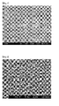
- Fig. 1 This is a 5000x microphotograph upon observing the structure of the target. Specifically, as shown in Fig. 1 , the number of micropores having an average diameter of less than 1 ⁇ m existing in an area of 40000 ⁇ m 2 on the target surface was 0 micropores. Pores having an average diameter of 1 ⁇ m or more also did not exist at all.
- the measurement was performed upon sampling from 9 locations in a cross shape. This average value was defined as the sintered compact density.
- the average value of the deflecting strength was measured by sampling from the middle of the center and the radial direction, and three locations in the peripheral vicinity, and this average value was defined as the deflecting strength.
- the average grain size of the sintered compact was calculated from the result of observing the structure of 9 locations in a cross shape.
- Example 1 the relative density of the sintered compact was 99.8%, the standard deviation of the variation in the density was ⁇ 1%, the deflecting strength was 61 MPa, and, with respect to the composition of the respective crystal grains, Ge was within the range of 17.8 to 26.6 at% and Sb was within the range of 17.8 to 26.6 at% ( ⁇ 20%), the average grain size of the sintered compact was 36 ⁇ m and the maximum grain size was 90 ⁇ m, and a favorable sintered compact was obtained.
- Example 2 In addition to the conditions of Example 1, additional pulverization was performed using a jet mill.
- the sintering conditions using this powder that is, the sintering conditions of the vacuum hot press and HIP were the same as Example 1.
- the structure of the target using the jet mill powder is shown in Fig. 2 .
- micropores having an average diameter of less than 1 ⁇ m existing in an area of 40000 ⁇ m 2 on the target surface could not be acknowledged at all.
- Example 1 Ag, In, Sb, Te powder raw materials respectively having a purity of 4N5 excluding gas components were used and blended to achieve a Ag 5 In 5 Sb 70 Te 20 alloy, and, under the same sintering conditions as Example 1; that is, based on vacuum hot press and HIP, a sintered compact having a purity of 4N5 and a composition of Ag 5 In 5 Sb 70 Te 20 was obtained. Specifically, excluding the component composition, a sintered compact was prepared to coincide with the conditions of Example 1.
- Micropores were examined in the sintered compact having a diameter of 400 mm that was prepared in Example 3. Consequently, nearly all of the micropores were eliminated. After HIP, the number of micropores having an average diameter of less than 1 ⁇ m existing in an area of 40000 ⁇ m 2 on the target surface was also 0 micropores. Moreover, pores having an average diameter of 1 ⁇ m or more also did not exist at all. As described above, it was discovered that the two-stage sintering for which appropriate conditions were set is extremely effective in eliminating the micropores.
- the measurement was performed upon sampling from 9 locations in a cross shape. This average value was defined as the sintered compact density.
- the average value of the deflecting strength was measured by sampling from the middle of the center and the radial direction, and three locations in the peripheral vicinity, and this average value was defined as the deflecting strength.
- the average grain size of the sintered compact was calculated from the result of observing the structure of 9 locations in a cross shape. Consequently, in Example 3, the relative density of the sintered compact was 99.8%, the standard deviation of the variation in the density was ⁇ 1%, the deflecting strength was 51 MPa, and the average grain size of the sintered compact was 38 ⁇ m, and a favorable sintered compact was obtained. In addition, there was no occurrence of grain dropping or generation of nodules caused by micropores during sputtering.
- the sintered compacts and the targets produced therefrom containing other chalcogenide elements (A) and Vb group elements (B) as well as other IVb group elements (C) or additive elements (D) were all favorable sintered compacts as with Example 1 and Example 2 in which the relative density of the sintered compact was 99.8% or higher, standard deviation in the variation of the density was ⁇ 1%, deflecting strength was 60 MPa or more, and average grain size of the sintered compact was 36 ⁇ m or less.
- the respective raw material powders of Te, Sb and Ge respectively having a purity of 99.995 (4N5) excluding gas components were melted to obtain a composition of Ge 22 Sb 22 Te 56 , and prepare a cast ingot.
- the raw materials of the respective elements were subject to acid cleaning and deionized water cleaning prior to the melting process in order to sufficiently eliminate impurities remaining on the surface. Consequently, a high purity Te 5 Sb 2 Ge 2 ingot maintaining a purity 99.995 (4N5) was obtained.
- the high purity Ge 22 Sb 22 Te 56 ingot was pulverized with a ball mill in an inert atmosphere to prepare raw material powder having an average grain size of approximately 30 ⁇ m, and a maximum grain size of approximately 90 ⁇ m (one figure of the grain size was rounded off).
- the foregoing conditions are the same as Example 1.
- the raw material powder was filled in a graphite die having a diameter of 400 mm, and subject to the following conditions in an inert atmosphere; namely, a final rise temperature of 600°C at a temperature rise rate of 15°C/min, and a final pressing pressure of 150 kgf/cm 2 .
- the raw material powder obtained in Comparative Example 1 was filled in a graphite die having a diameter of 400 mm, and subject to the following conditions in an inert atmosphere; namely, a final rise temperature of 450°C at a temperature rise rate of 5°C/min, and a final pressing pressure of 150 kgf/cm 2 .
- the raw material powder obtained in Comparative Example 1 was filled in a graphite die having a diameter of 400 mm, and subject to the following conditions in an inert atmosphere; namely, a final rise temperature of 600°C at a temperature rise rate of 5°C/min, and a final pressing pressure of 80 kgf/cm 2 .
- the raw material powder obtained in Comparative Example 1 was filled in a graphite die having a diameter of 400 mm, and subject to the following conditions in an inert atmosphere; namely, a final rise temperature of 600°C at a temperature rise rate of 5°C/min, and a final pressing pressure of 150 kgf/cm 2 .
- the pressing pressure was strictly adjusted to P ⁇ 20 kgf/cm 2 since this will be P ⁇ 150 (kgf/cm 2 )/600°C ⁇ 100°C at a heating temperature of 100°C.
- the pressing pressure was strictly adjusted to P ⁇ 45 kgf/cm 2 at a heating temperature of 200°C and to P ⁇ 72 kgf/cm 2 at a heating temperature of 300°C in order to achieve the hot press pressurization pattern according to the foregoing formula.
- this production method clearly differs from the present invention with respect to the point that HIP was not performed.
- Example 2 In addition to the conditions of Example 1, additional pulverization was performed using a jet mill.
- the sintering conditions using this powder that is, the sintering conditions of the vacuum hot press and HIP were the same as Example 1. Nevertheless, the sintered compact was produced without performing HIP, and the conditions are for comparison with Example 2.
- the composition was as follows; namely, Ge was within the range of 21.1 to 23.3 at%, and Sb was within the range of 21.1 to 23.3 at% ( ⁇ 5%).
- the average crystal grain size was 2.2 ⁇ m
- maximum grain size was 8 ⁇ m
- oxygen concentration was 1900 ppm
- relative density of the sintered compact was 99.8%
- standard deviation in the variation of the density was ⁇ 1%
- deflecting strength was 75 MPa.
- the structure of the target prepared with this production method is shown in Fig. 4 . As shown in Fig. 4 , numerous micropores were observed.
- Comparative Example 1 the relative density of the sintered compact was 98.5%, the standard deviation of the variation in the density was 3%, the deflecting strength was 32 MPa, and the average grain size of the sintered compact was 42 ⁇ m, and a fragile sintered compact was obtained.
- the number of micropores having an average diameter of less than 1 ⁇ m existing in an area of 40000 ⁇ m 2 on the target surface was numerous at 500 micropores.
- the relative density of the sintered compact was 94%
- the standard deviation of the variation in the density was 1%
- the deflecting strength was 26 MPa
- the average grain size of the sintered compact was 35 ⁇ m
- a fragile sintered compact was obtained.
- the number of micropores having an average diameter of less than 1 ⁇ m existing in an area of 40000 ⁇ m 2 on the target surface was numerous at 1000 micropores.
- the relative density of the sintered compact was 96.1%
- the standard deviation of the variation in the density was 1%
- the deflecting strength was 29 MPa
- the average grain size of the sintered compact was 39 ⁇ m
- a fragile sintered compact was obtained.
- the number of micropores having an average diameter of less than 1 ⁇ m existing in an area of 40000 ⁇ m 2 on the target surface was numerous at 1500 micropores.
- the relative density of the sintered compact was 99.2%
- the standard deviation of the variation in the density was 1%
- the deflecting strength was 39 MPa
- the average grain size of the sintered compact was 42 ⁇ m
- a fragile sintered compact was obtained.
- the number of micropores having an average diameter of less than 1 ⁇ m existing in an area of 40000 ⁇ m 2 on the target surface was numerous at 1200 micropores.
- the relative density of the sintered compact was 99.2%
- the standard deviation of the variation in the density was 1%
- the deflecting strength was 75 MPa
- the average grain size of the sintered compact was 42 ⁇ m
- a fragile sintered compact was obtained in comparison to Example 2.
- the number of micropores having an average diameter of less than 1 ⁇ m existing in an area of 40000 ⁇ m 2 on the target surface was numerous at 7000 micropores.
- the sintered compacts prepared in Comparative Example 1 to 5 were respectively bonded to a copper alloy backing plate using indium so that the bonding thickness would become 0.4 to 1.4 mm according to the same process as Example 1. Subsequently, a target plate was prepared by performing cutting work. Consequently, warping occurred after bonding, and some cracks were observed after the bonding, and a macro pattern was observed at various parts of the target . Sputtering was performed using this target, but the particle generation rate was significantly high at 300 to several thousand particles, and was far lower than a practically applicable level.
- the present invention discovered that defects of micropores and the like are a major cause of the generation of particles, and offers a method of considerably reducing the defects of such micropores from the sintered compact target.
- the present invention is able to significantly reduce defects of micropores and the like by improving the production process. Since the sintered compact having the composition of the present invention is extremely fragile, if a large diameter sputtering target is prepared and this is bonded with a backing plate, there was a problem in that cracks would occur on the target surface or the target itself would crack due to the difference in thermal expansion. Nevertheless, the present invention is able to produce a high strength, high density and large diameter sintered compact or sputtering target.
- phase change recording material that is, as a medium for recording information by using phase transformation
Landscapes
- Chemical & Material Sciences (AREA)
- Engineering & Computer Science (AREA)
- Mechanical Engineering (AREA)
- Materials Engineering (AREA)
- Metallurgy (AREA)
- Organic Chemistry (AREA)
- Chemical Kinetics & Catalysis (AREA)
- Manufacturing & Machinery (AREA)
- Inorganic Chemistry (AREA)
- Physical Vapour Deposition (AREA)
- Powder Metallurgy (AREA)
Abstract
Description
- The present invention relates to a method of producing a sintered compact target capable of reducing minute defects within the sintered compact and having high deflecting strength, and containing a Vb group element (A) and a chalcogenide element (B) or containing the elements (A) and (B) and additionally a IVb group element (C) and/or an additive element (D).
- In recent years, a thin film formed from a Ge-Sb-Te base material is being used as a material for use in phase change recording; that is, as a medium for recording information by using phase transformation.
As a method of forming this thin film formed from the Ge-Sb-Te base alloy material, it is standard to use a means generally referred to as a physical vapor deposition method such as the vacuum deposition method or the sputtering method. In particular, the thin film is often formed using the magnetron sputtering method from the perspective of operability and film stability. - Formation of films by way of the sputtering method is performed by physically colliding positive ions such as Ar ions to a target disposed on a cathode, using that collision energy to discharge materials configuring the target, and laminating a film having roughly the same composition as the target material on the opposite anode-side substrate.
The coating method based on the sputtering method is characterized in that it is possible to form films of various thicknesses; for instance, from a thin film of angstrom units to a thick film of several ten µm, with a stable deposition speed by adjusting the processing time, power supply and the like. - Conventionally, in order to inhibit the generation of particles that occurs during the sputtering process, a high density sintered compact having a relative density of approximately 98.8% was prepared by sintering, via hot press, raw material powder having high purity and a prescribed grain size.
A sintered compact that is sintered by combining a chalcogenide element (S, Se, Te), a Vb group element (Bi, Sb, As, P, N), and additionally a IVb group element (Pb, Sn, Ge, Si, C) and an additive element (Ag, Au, Pd, Pt, B, Al, Ga, In, Ti, Zr) generally has low thermal conductivity. - If there are minute defects (micropores; gaps of less than 1 µm that appear at the grain boundary portion) in this kind of sintered compact having low thermal conductivity, since the dispersion of heat is inhibited by the defects, heat will remain at the periphery thereof, and components (for instance, GeTe2) having high vapor pressure will be volatilized from such portion.
Meanwhile, the remaining portion will take on a crater shape and become an abnormally eroded portion. The surface structure of a target having the foregoing defects will become the source of causing grain dropping or generating nodules, and additionally cause a major problem in that particles are generated easily. - As conventional technology, there is a method of producing a sputtering target of phase-change ZnS and SiO2 having a relative density of 98% or higher by using HIP (hot isostatic pressing) and performing the treatment at a temperature of 1000°C or higher and a pressure of 100 MPa or more (refer to Patent Document 1).
Nevertheless, in the foregoing case, if only the HIP process of pressurizing the product using high-pressure Ar gas is performed, since there will always be gas at the periphery thereof, there is a drawback in that it is not possible to obtain a dense sintered compact that can be obtained with the vacuum hot press method of advancing the sintering process while eliminating the gas that is generated from the product.
[Patent Document 1] Japanese Published Unexamined Application No.2000-26960 - The present invention provides a sintered compact target capable of reducing minute defects within the sintered compact and having high deflecting strength, and containing a Vb group element (A) and a chalcogenide element (B) or containing the elements (A) and (B) and additionally a IVb group element (C) and/or an additive element (D), and a method of producing such a sintered compact target, and additionally provides technology that is able to eliminate the source of grain dropping or generation of nodules in the target during sputtering, and additionally inhibit the generation of particles.
This is groundbreaking technology of being able to form a low-oxygen sintered compact while initially eliminating unnecessary gas components based on vacuum hot press from the Sb-Te alloy such as GST in which pores caused by insufficient sintering due to the oxidation of the powder surface are easily formed, and further completely crushing and eliminating the remaining minute pores.
The present invention can be applied to both pulverized powder having an average grain size of approximately 30 µm and fine powder having an average grain size of less than 3 µm. In addition, although there are cases where the grains mutually become cross-linked due to necking during hydrogen reduction, and the gaps thereof remain as pores, if the present technology is employed, the foregoing pores can also be eliminated completely, and it is also possible to produce a low-oxygen product.
In addition, it is possible to produce a high density, high strength and large diameter sintered compact target, and the present invention provides a sintered compact containing a chalcogenide element (A) and a Vb group element (B) or containing the element (A) and (B) and additionally a IVb group element (C) and/or an additive element (D) which is free from cracks even when it is assembled and used as a sputtering target-backing plate assembly, as well as a method of producing such a sintered compact. - As a result of devising the sintering conditions, the present inventors discovered that the foregoing problems can be solved.
Based on the foregoing discovery, the present invention provides: - 1. A sintered compact target containing an element of (A) and an element of (B) below, wherein the sintered compact target is free from pores having an average diameter of 1 µm or more, and the number of micropores having an average diameter of less than 1 µm existing in an area of 40000 µm2 of the target surface is 100 micropores or less:
- (A): one or more chalcogenide elements selected from S, Se, and Te; and
- (B): one or more Vb group elements selected from Bi, Sb, As, P, and N; and
- 2. A sintered compact target containing an element of (A) and an element of (B) below as well as one or more elements selected from (C) or (D) below, wherein the sintered compact target is free from pores having an average diameter of 1 µm or more, and the number of micropores having an average diameter of 0.1 to 1 µm existing in an arbitrarily selected area of 40000 µm2 of the target surface is 100 micropores or less:
- (A): one or more chalcogenide elements selected from S, Se, and Te;
- (B): one or more Vb group elements selected from Bi, Sb, As, P, and N;
- (C): one or more IVb group elements selected from Pb, Sn, Ge, Si, and C; and
- (D): one or more elements selected from Ag, Au, Pd, Pt, B, Al, Ga, In, Ti, and Zr.
- The present invention additionally provides:
- 3. The sintered compact target according to paragraph 1 or paragraph 2 above, wherein the element of (A) is Te, the element of (B) is Sb, the element of (C) is Ge, and the element of (D) is one or more elements selected from Ag, Ga, and In;
- 4. The sintered compact target according to paragraph 3, wherein the sintered compact target is one among Ge-Sb-Te, Ag-In-Sb-Te, and Ge-In-Sb-Te;
- 5. The sintered compact target according to any one of paragraphs 1 to 4 above, wherein the average crystal grain size of the structure of the sintered compact target is 50 µm or less, the deflecting strength is 40 MPa or more, the relative density is 99% or higher, the standard deviation of the relative density is 1%, and the variation in the composition of the respective crystal grains configuring the target is less than ± 20% of the overall average composition; and
- 6. The sintered compact target according to paragraph 5 above, wherein the average crystal grain size is 10 µm or less.
- The present invention further provides:
- 7. A method of producing a sintered compact containing an element of (A) and an element of (B) below, including the steps of mixing raw material powder composed of the respective elements or raw material powder of an alloy of two or more elements, and vacuum hot press the mixed powder under conditions that satisfy the following formula: P (pressure) ≤ {Pf/(Tf - T0)} × (T - T0) + P0, (Pf: final pressure, P0: atmospheric pressure, Tf: final temperature, T: heating temperature, T0:
- room temperature, temperatures are expressed in degrees Celsius)), and further performing HIP treatment under the conditions of Phip > 5 × Pf, wherein the sintered compact is free from pores having an average diameter of 1 µm or more, and the number of micropores having an average diameter of less than 1 µm existing in an area of 40000 µm2 of the target surface is 100 micropores or less:
- (A): one or more chalcogenide elements selected from S, Se, and Te; and
- (B): one or more Vb group elements selected from Bi, Sb, As, P, and N.
- room temperature, temperatures are expressed in degrees Celsius)), and further performing HIP treatment under the conditions of Phip > 5 × Pf, wherein the sintered compact is free from pores having an average diameter of 1 µm or more, and the number of micropores having an average diameter of less than 1 µm existing in an area of 40000 µm2 of the target surface is 100 micropores or less:
- 8. A method of producing a sintered compact containing an element of (A) and an element of (B) below as well as one or more elements selected from (C) or (D) below, including the steps of mixing raw material powder composed of the respective elements or raw material powder of an alloy of two or more elements, and vacuum hot press the mixed powder under conditions that satisfy the following formula: P (pressure) ≤ {Pf/(Tf - T0)} × (T - T0) + P0, (Pf: final pressure, P0:
- atmospheric pressure, Tf: final temperature, T: heating temperature, T0: room temperature, temperatures are expressed in degrees Celsius)), and further performing HIP treatment under the conditions of Phip > 5 × Pf, wherein the sintered compact is free from pores having an average diameter of 1 µm or more, and the number of micropores having an average diameter of 0.1 to 1 µm existing in an area of 40000 µm2 of the target surface is 100 micropores or less:
- (A): one or more chalcogenide elements selected from S, Se, and Te;
- (B): one or more Vb group elements selected from Bi, Sb, As, P, and N;
- (C): one or more IVb group elements selected from Pb, Sn, Ge, Si, and C; and
- (D): one or more elements selected from Ag, Au, Pd, Pt, B, Al, Ga, In, Ti, and Zr.
- atmospheric pressure, Tf: final temperature, T: heating temperature, T0: room temperature, temperatures are expressed in degrees Celsius)), and further performing HIP treatment under the conditions of Phip > 5 × Pf, wherein the sintered compact is free from pores having an average diameter of 1 µm or more, and the number of micropores having an average diameter of 0.1 to 1 µm existing in an area of 40000 µm2 of the target surface is 100 micropores or less:
- The present invention also provides:
- 9. The method of producing a sintered compact according to paragraph 7 or paragraph 8 above,
wherein sintering is performed by using raw material powder in which the element of (A) is Te, the element of (B) is Sb, the element of (C) is Ge, and the element of (D) is one or more elements selected from Ag, Ga, and In. - 10. The method of producing a sintered compact according to paragraph 9 above,
wherein the sintered compact is one among Ge-Sb-Te, Ag-In-Sb-Te, and Ge-In-Sb-Te. - 11. The method of producing a sintered compact according to any one of paragraphs 7 to 10 above, wherein sintering is performed by using raw material powder of elements constituting the sintered compact in which the raw material powder is composed of an alloy, a compound or a mixture of constituent elementary substances or constituent elements, and the average grain size is 0.1 µm to 50 µm, the maximum grain size is 90 µm or less, and the purity is 4N or higher.
- 12. The method of producing a sintered compact according to any one of paragraphs 7 to 11 above, wherein, during the course of heating temperature T rising from 100 to 500°C during the hot press, the pressure is maintained at a constant level for 10 to 120 minutes at least in a part of the heating temperature range.
- Conventionally, when producing a sintered compact target using raw material powder containing a chalcogenide element (A) and a Vb group element (B) or raw material powder additionally containing a IVb group element (C) or an intended additive element (D), numerous defects of micropores would exist and become the source of grain dropping and nodules, and this is a major cause of the generation of particles during sputtering deposition. The present invention discovered that defects of micropores and the like are a major cause of the generation of particles, and offers a method of considerably reducing the defects of such micropores from the sintered compact target.
Since the sintered compact having the composition of the present invention is extremely fragile, if a large diameter sputtering target is prepared and this is bonded with a backing plate, there was a problem in that cracks would occur on the target surface or the target itself would crack due to the difference in thermal expansion. Nevertheless, the present invention is able to produce a high strength, high density and large diameter sintered compact or sputtering target capable of considerably reducing defects such as micropores by improving the production process.
The present invention yields a superior effect of being able to prevent the generation of cracks and the like even when the target is bonded to a backing plate, and also keep the warping to be within a tolerable range. -
- [
Fig. 1 ] A 5000x microphotograph upon observing the target structure of Example 1. - [
Fig. 2 ] A 5000x microphotograph upon observing the target structure of Example 2. - [
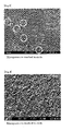
Fig. 3 ] A 5000x microphotograph upon observing the target structure of Comparative Example 1. - [
Fig. 4 ] A 5000x microphotograph upon observing the target structure of Comparative Example 5. - As described above, upon producing a sintered compact, the following steps are performed; namely, mixing raw material powder composed of the respective elements or raw material powder of an alloy of two or more elements, and vacuum hot pressing the mixed powder under conditions that satisfy the following formula: P (pressure) ≤ {Pf/(Tf - T0)} × (T - T0) + P0 (Pf: final pressure, Tf: final temperature, P0: atmospheric pressure, T: heating temperature, T0: room temperature (temperatures are expressed in degrees Celsius)):
- (A): one or more chalcogenide elements selected from S, Se, and Te
- (B): one or more Vb group elements selected from Bi, Sb, As, P, and N In addition, as necessary, the following element of (C) or element of (D) is added.
- (C): one or more IVb group elements selected from Pb, Sn, Ge, Si, and C
- (D): one or more elements selected from Ag, Au, Pd, Pt, B, Al, Ga, In, Ti, and Zr
- Controlling the pressure rise and temperature rise conditions of the hot press in a vacuum as described above is an important and basic process, and is achieved by relatively and gradually increasing the pressure P in relation to the temperature T during the course of the temperature rise.
When deviating from these conditions, it becomes difficult to effectively inhibit the generation of defects such as micropores, and it is also virtually impossible to product a large diameter sintered compact or sputtering target having high strength and high density.
With the foregoing vacuum hot press, the material of the present invention which is easily oxidized can be sintered in a low-oxygen state. In addition, it is also possible to simultaneously prevent the inclusion of unwanted gas components. - The sintered compact target obtained based on the production method of the present invention is able to considerably reduce the defects of micropores and the like. In addition, a large diameter sputtering target having a mechanically high strength is able to inhibit and improve the particle generation rate of a conventional target having a diameter of approximately 300 mm. This is because the grain boundary of the sintered compact has been strengthened based on the fine uniform crystal structure that is free from pores. This can only be achieved based on the foregoing condition of the present invention.
- One of the essential basic conditions for achieving the present invention is to perform hot pressing under conditions that satisfy P (pressure) ≤ {Pf/(Tf - T0)} × (T - T0) + P0, (Pf: final pressure, Tf: final temperature, P0: atmospheric pressure, T: heating temperature, T0: room temperature, temperatures are expressed in degrees Celsius), but it is effect to stabilize the pressure for 10 to 120 minutes during the course of the temperature T rising from 100 to 500°C.
- By devising the sintering conditions; that is, by combining hot press and HIP, it is possible to produce a low-oxygen, high density sintered compact that is free from micropores.
HIP is performed under the same achieving temperature condition as the hot press, and under the condition of PHIP > 5 × Pf. HIP is able to completely eliminate the micropores that are remaining internally. The HIP treatment is an important requirement for achieving the number of micropores having an average diameter of 0.1 to 1 µm existing in an area of 40000 µm2 on the target surface to be 10 micropores or less, and even 1 micropore or less. - Further, it is desirable to keep the content of oxygen as an impurity to be 2000 ppm or less. The inclusion of gas components in excess of the foregoing value will cause the generation of a nonconductor such as oxides. Thus, the reduction of oxygen will prevent arcing and thereby inhibit the generation of particles caused by the arcing. Although this is not a special condition in the present invention, it is a preferable condition.
- The Sb-Te-based alloy sintered compact sputtering target of the present invention may contain, at maximum 20 at%, one or more elements selected from Ag, Au, Pd, Pt, B, Al, Ga, In, Ti, and Zr as additive elements. So as long as the amount is within the foregoing range, in addition to obtaining the intended glass transition temperature, transformation rate and electrical resistance value, it is also possible to minimize the surface defects resulting from the machining process, and the particles can also be effectively inhibited.
- Based on the above, it is possible to obtain a sintered compact having a diameter of 380 mm or more and a thickness of 20 mm or less containing a chalcogenide element (A) and a Vb group element (B) and, as needed, additionally containing a IVb group element (C) and/or additive element (D).
Consequently, it is possible to obtain a sintered compact composed of a chalcogenide element (A) and a Vb group element (B) or a sintered compact composed of a chalcogenide element (A) and a Vb group element (B) as well as a IVb group element (C) and/or additive element (D) having a sintered structure in which the average grain size is 50 µm or less, the deflecting strength is 40 MPa or more, the relative density is 99% or higher, and the standard deviation of the in-plane density of the sintered compact surface is less than 1%.
The sputtering target produced from the sintered compact obtained as described above is able to considerably reduce defects such as micropores, is free from cracks even when it is bonded to a backing plate, and yields a superior effect of also maintaining the warping within a tolerable range. - As described above, the sintered compact sputtering target is free from defects such as micropores, and a target having a uniform fine crystal structure will have reduced surface irregularities caused by sputter erosion and yield a half-mirror appearance, is free from a crater-shaped abnormal structure, and is able to effectively inhibit the generation of particles caused by the redeposited film on the target surface peeling off. Consequently, it is possible to effectively inhibit the generation of particles, abnormal discharge, and nodules during the foregoing sputtering process.
- With the sputtering target of the present invention, it is possible to make the content of oxygen to be 2000 ppm or less, in particular 1000 ppm or less, and even 500 ppm or less. The reduction of oxygen is effective in further reducing the generation of particles and the generation of abnormal discharge.
- The present invention is now explained in detail with reference to the Examples. These Examples are merely illustrative, and the present invention shall in no way be limited thereby. In other words, various modifications and other embodiments based on the technical spirit claimed in the claims shall be included in the present invention as a matter of course.
- The respective raw material powders of Te, Sb and Ge respectively having a purity of 99.995 (4N5) excluding gas components were melted to obtain a composition of Ge22Sb22Te56, and slowly cooled in a furnace to prepare a cast ingot. The raw materials of the respective elements were subject to acid cleaning and deionized water cleaning prior to the melting process in order to sufficiently eliminate impurities remaining on the surface.
Consequently, a high purity Ge22Sb22Te56 ingot maintaining a purity 99.995 (4N5) was obtained. Subsequently, the high purity Ge22Sb22Te56 ingot was pulverized with a ball mill in an inert atmosphere to prepare raw material powder having an average grain size of approximately 30 µm, and a maximum grain size of approximately 90 µm (one figure of the grain size was rounded off). - Subsequently, the raw material powder was filled in a graphite die having a diameter of 400 mm, and subject to the following conditions in an inert atmosphere; namely, a final rise temperature of 600°C at a temperature rise rate of 5°C/min, and a final pressing pressure of 150 kgf/cm2. Further, as a result of controlling the hot press pressurization pattern to satisfy, with respect to the temperature, the conditions of the following formula: P (pressure) ≤ {Pf/(Tf - T0)} × (T - T0) + P0, (Pf: final pressure, Tf: final temperature, P0: atmospheric pressure, T: heating temperature, T0: room temperature, temperatures are expressed in degrees Celsius), a Ge22Sb22Te56 intermediate sintered compact was prepared.
- In the foregoing case, for instance, based on the foregoing formula, the pressing pressure was strictly adjusted to P ≤ 20 kgf/cm2 since this will be P (kgf/cm2) ≤ {150 (kgf/cm2) / (600°C - 25°C)} × (100°C - 25°C) + 1 (kgf/cm2) at a heating temperature of 100°C. Similarly, the pressing pressure was strictly adjusted to P ≤ 5 kgf/cm2 at a heating temperature of 200°C and to P ≤ 72 kgf/cm2 at a heating temperature of 300°C in order to achieve the hot press pressurization pattern according to the foregoing formula.
- Specifically, the pressing pressure was set to P = 0 kgf/cm2 when the heating temperature is less than 100°C, to the pressing pressure of P = 20 kgf/cm2 when the heating temperature is 100 to 200°C, to the pressing pressure of P = 45 kgf/cm2 when the heating temperature is 200 to 300°C, to the pressing pressure of P = 72 kgf/cm2 when the heating temperature is 300 to the final rise temperature of 600°C, and to the pressing pressure of P = 150 kgf/cm2 when the heating temperature is 600°C.
- Incidentally, since the pressing pressure can be gradually increased as described above pursuant to the increase in the heating temperature, the final pressing pressure will reach 150 kgf/cm2 more quickly. Thus, it can be said that the production time efficiency can be shortened and the production efficiency can be improved by just that much. Nevertheless, an absolute condition is not to deviate from the foregoing formula. Moreover, the sintered compact was retained for 2 hours after reaching the final rise temperature and the final pressing pressure.
- HIP treatment was further performed to the obtained intermediate sintered compact having a diameter of 400 mm under the condition of PHIP = 750 to 2000 kgf/cm2. Specifically, HIP treatment was performed under the following five types of conditions; namely, PHIP = 750 kgf/cm2, PHIP = 900 kgf/cm2, PHIP = 1000 kgf/cm2, PHIP = 1500 kgf/cm2, and PHIP = 2000 kgf/cm2.
The target shown inFig. 1 is an example of PHIP = 1000 kgf/cm2, and is the structure of a target that used standard pulverized powder, and had a crystal grain size of 30 µm or less.
WithFig. 3 corresponding to Comparative Example 1 described later, at the hot press stage, 5 micropores (micropores having an average diameter of 0.1 to 1 µm) were observed at the grain boundary. This corresponds to approximately 500 micropores in an area of 40000 µm2. - Subsequently, the obtained final sintered compact was subject to cutting work in order to prepare a target. Based on the foregoing HIP treatment, nearly all of the micropores were eliminated. The results are shown in
Fig. 1 . This is a 5000x microphotograph upon observing the structure of the target.
Specifically, as shown inFig. 1 , the number of micropores having an average diameter of less than 1 µm existing in an area of 40000 µm2 on the target surface was 0 micropores. Pores having an average diameter of 1 µm or more also did not exist at all. - Although this result is based on a representative example of performing the HIP treatment at PHIP = 1000 kgf/cm2, even with the targets that were subject to the HIP treatment based on the other four conditions, the number of micropores having an average diameter of less than 1 µm existing in an area of 40000 µm2 on the target surface was also 0 micropores. Pores having an average diameter of 1 µm or more also did not exist at all.
As described above, it was discovered that the two-stage sintering for which appropriate conditions were set is extremely effective in eliminating the micropores. - Moreover, in order to measure the density, the measurement was performed upon sampling from 9 locations in a cross shape. This average value was defined as the sintered compact density. The average value of the deflecting strength was measured by sampling from the middle of the center and the radial direction, and three locations in the peripheral vicinity, and this average value was defined as the deflecting strength.
The average grain size of the sintered compact was calculated from the result of observing the structure of 9 locations in a cross shape. Consequently, in Example 1, the relative density of the sintered compact was 99.8%, the standard deviation of the variation in the density was < 1%, the deflecting strength was 61 MPa, and, with respect to the composition of the respective crystal grains, Ge was within the range of 17.8 to 26.6 at% and Sb was within the range of 17.8 to 26.6 at% (± 20%), the average grain size of the sintered compact was 36 µm and the maximum grain size was 90 µm, and a favorable sintered compact was obtained. - Using similar methods, favorable bonding properties have been confirmed regardless of the type of backing plate; regardless of whether they are formed from copper alloy or aluminum alloy.
Subsequently, the target surface was observed, but no macro pattern could be found across the entire target.
Sputtering was performed using this target, and this target had an extremely low particle generation rate of 18 particles or less in comparison to a conventional high quality, high density small-sized target (diameter 280 mm). In addition, there was no occurrence of grain dropping or generation of nodules caused by micropores during sputtering. - In addition to the conditions of Example 1, additional pulverization was performed using a jet mill. The sintering conditions using this powder; that is, the sintering conditions of the vacuum hot press and HIP were the same as Example 1. The structure of the target using the jet mill powder is shown in
Fig. 2 .
As shown inFig. 2 , as with Example 1, micropores having an average diameter of less than 1 µm existing in an area of 40000 µm2 on the target surface could not be acknowledged at all.
It was possible to obtain a sintered compact having composition uniformity in which Ge is within the range 21.1 to 23.3 at% and Sb is within the range of 21.1 to 23.3 at% (± 5%), average crystal grain size was 2.2 µm and maximum grain size was 8 µm yielding an ultrafine structure, oxygen concentration was 1900 ppm, relative density was 99.8%, standard deviation in the variation of the density was < 1%, and deflecting strength was 90 MPa. - Ag, In, Sb, Te powder raw materials respectively having a purity of 4N5 excluding gas components were used and blended to achieve a Ag5In5Sb70Te20 alloy, and, under the same sintering conditions as Example 1; that is, based on vacuum hot press and HIP, a sintered compact having a purity of 4N5 and a composition of Ag5In5Sb70Te20 was obtained. Specifically, excluding the component composition, a sintered compact was prepared to coincide with the conditions of Example 1.
- Micropores were examined in the sintered compact having a diameter of 400 mm that was prepared in Example 3. Consequently, nearly all of the micropores were eliminated. After HIP, the number of micropores having an average diameter of less than 1 µm existing in an area of 40000 µm2 on the target surface was also 0 micropores. Moreover, pores having an average diameter of 1 µm or more also did not exist at all. As described above, it was discovered that the two-stage sintering for which appropriate conditions were set is extremely effective in eliminating the micropores.
- Moreover, in order to measure the density, the measurement was performed upon sampling from 9 locations in a cross shape. This average value was defined as the sintered compact density. The average value of the deflecting strength was measured by sampling from the middle of the center and the radial direction, and three locations in the peripheral vicinity, and this average value was defined as the deflecting strength. The average grain size of the sintered compact was calculated from the result of observing the structure of 9 locations in a cross shape.
Consequently, in Example 3, the relative density of the sintered compact was 99.8%, the standard deviation of the variation in the density was < 1%, the deflecting strength was 51 MPa, and the average grain size of the sintered compact was 38 µm, and a favorable sintered compact was obtained. In addition, there was no occurrence of grain dropping or generation of nodules caused by micropores during sputtering. - Although not shown in the Examples, the sintered compacts and the targets produced therefrom containing other chalcogenide elements (A) and Vb group elements (B) as well as other IVb group elements (C) or additive elements (D) were all favorable sintered compacts as with Example 1 and Example 2 in which the relative density of the sintered compact was 99.8% or higher, standard deviation in the variation of the density was < 1%, deflecting strength was 60 MPa or more, and average grain size of the sintered compact was 36 µm or less.
- Moreover, warping after the bonding could not be acknowledged at all, and there were no cracks after the bonding. In addition, the macro pattern was observed during the polishing process, but no macro pattern could be found across the entire target. Sputtering was performed using this target, and this target showed a particle generation rate that is equal to or less than a conventional high quality, high density small-sized target (diameter 280 mm).
- The respective raw material powders of Te, Sb and Ge respectively having a purity of 99.995 (4N5) excluding gas components were melted to obtain a composition of Ge22Sb22Te56, and prepare a cast ingot. The raw materials of the respective elements were subject to acid cleaning and deionized water cleaning prior to the melting process in order to sufficiently eliminate impurities remaining on the surface.
Consequently, a high purity Te5Sb2Ge2 ingot maintaining a purity 99.995 (4N5) was obtained. Subsequently, the high purity Ge22Sb22Te56 ingot was pulverized with a ball mill in an inert atmosphere to prepare raw material powder having an average grain size of approximately 30 µm, and a maximum grain size of approximately 90 µm (one figure of the grain size was rounded off). The foregoing conditions are the same as Example 1. - Subsequently, the raw material powder was filled in a graphite die having a diameter of 400 mm, and subject to the following conditions in an inert atmosphere; namely, a final rise temperature of 600°C at a temperature rise rate of 15°C/min, and a final pressing pressure of 150 kgf/cm2. Further, as a result of controlling the hot press pressurization pattern to satisfy, with respect to the temperature, the conditions of the following formula: P (pressure) ≤ {Pf/(Tf - T0)} × (T - T0) + P0, (Pf: final pressure, Tf: final temperature, P0: atmospheric pressure, T: heating temperature, T0: room temperature, temperatures are expressed in degrees Celsius), a Ge22Sb22Te56 sintered compact was prepared. HIP was not performed. The structure of the target prepared based on the foregoing conditions is shown in
Fig. 3 . As shown inFig. 3 , micropores can be observed at the crystal grain boundary. - The raw material powder obtained in Comparative Example 1 was filled in a graphite die having a diameter of 400 mm, and subject to the following conditions in an inert atmosphere; namely, a final rise temperature of 450°C at a temperature rise rate of 5°C/min, and a final pressing pressure of 150 kgf/cm2. Further, as a result of controlling the hot press pressurization pattern to satisfy, with respect to the temperature, the conditions of the following formula: P (pressure) ≤ {Pf/(Tf - T0)} × (T - T0) + P0, (Pf: final pressure, Tf: final temperature, P0: atmospheric pressure, T: heating temperature, T0: room temperature, temperatures are expressed in degrees Celsius), a Ge22Sb22Te56 sintered compact was prepared. HIP was not performed.
- The raw material powder obtained in Comparative Example 1 was filled in a graphite die having a diameter of 400 mm, and subject to the following conditions in an inert atmosphere; namely, a final rise temperature of 600°C at a temperature rise rate of 5°C/min, and a final pressing pressure of 80 kgf/cm2. Further, as a result of controlling the hot press pressurization pattern to satisfy, with respect to the temperature, the conditions of the following formula: P (pressure) ≤ {Pf/(Tf - T0)} × (T - T0) + P0, (Pf: final pressure, Tf: final temperature, P0: atmospheric pressure, T: heating temperature, T0: room temperature, temperatures are expressed in degrees Celsius), a sintered compact was prepared. HIP was not performed.
- The raw material powder obtained in Comparative Example 1 was filled in a graphite die having a diameter of 400 mm, and subject to the following conditions in an inert atmosphere; namely, a final rise temperature of 600°C at a temperature rise rate of 5°C/min, and a final pressing pressure of 150 kgf/cm2. Further, as a result of controlling the hot press pressurization pattern outside the conditions of the following formula: P (pressure) ≤ {Pf/(Tf - T0)} × (T - T0) + P0, (Pf: final pressure, Tf: final temperature, P0: atmospheric pressure, T: heating temperature, T0: room temperature, temperatures are expressed in degrees Celsius), a sintered compact was prepared.
As the condition outside the foregoing formula, the pressing pressure was raised to P = 75 kgf/cm2 at the stage when the heating temperature was 100°C in order to accelerate the pressurization process. HIP was not performed. - As described above, with the conditions of the present invention, based on the foregoing formula, the pressing pressure was strictly adjusted to P ≤ 20 kgf/cm2 since this will be P ≤ 150 (kgf/cm2)/600°C × 100°C at a heating temperature of 100°C. Similarly, the pressing pressure was strictly adjusted to P ≤ 45 kgf/cm2 at a heating temperature of 200°C and to P ≤ 72 kgf/cm2 at a heating temperature of 300°C in order to achieve the hot press pressurization pattern according to the foregoing formula. However, the condition of accelerating the pressurization process by raising the pressing pressure to P = 72 kgf/cm2 deviates from the conditions of the present invention. In addition, this production method clearly differs from the present invention with respect to the point that HIP was not performed.
- In addition to the conditions of Example 1, additional pulverization was performed using a jet mill. The sintering conditions using this powder; that is, the sintering conditions of the vacuum hot press and HIP were the same as Example 1. Nevertheless, the sintered compact was produced without performing HIP, and the conditions are for comparison with Example 2. The composition was as follows; namely, Ge was within the range of 21.1 to 23.3 at%, and Sb was within the range of 21.1 to 23.3 at% (± 5%).
With the obtained sintered compact, the average crystal grain size was 2.2 µm, maximum grain size was 8 µm, oxygen concentration was 1900 ppm, relative density of the sintered compact was 99.8%, standard deviation in the variation of the density was < 1%, and deflecting strength was 75 MPa.
The structure of the target prepared with this production method is shown inFig. 4 . As shown inFig. 4 , numerous micropores were observed. - In order to measure the density of the sintered compact having a diameter of 400 mm obtained in Comparative Examples 1 to 5, the measurement was performed upon sampling from 9 locations in a cross shape. This average value was defined as the sintered compact density. The average value of the deflecting strength was measured by sampling from the middle of the center and the radial direction, and three locations in the peripheral vicinity, and this average value was defined as the deflecting strength. The average grain size of the sintered compact was calculated from the result of observing the structure of 9 locations in a cross shape. These measurement conditions are the same as Example 1.
- Consequently, in Comparative Example 1, the relative density of the sintered compact was 98.5%, the standard deviation of the variation in the density was 3%, the deflecting strength was 32 MPa, and the average grain size of the sintered compact was 42 µm, and a fragile sintered compact was obtained. The number of micropores having an average diameter of less than 1 µm existing in an area of 40000 µm2 on the target surface was numerous at 500 micropores.
- Similarly, in Comparative Example 2, the relative density of the sintered compact was 94%, the standard deviation of the variation in the density was 1%, the deflecting strength was 26 MPa, and the average grain size of the sintered compact was 35 µm, and a fragile sintered compact was obtained. The number of micropores having an average diameter of less than 1 µm existing in an area of 40000 µm2 on the target surface was numerous at 1000 micropores.
- Similarly, in Comparative Example 3, the relative density of the sintered compact was 96.1%, the standard deviation of the variation in the density was 1%, the deflecting strength was 29 MPa, and the average grain size of the sintered compact was 39 µm, and a fragile sintered compact was obtained. The number of micropores having an average diameter of less than 1 µm existing in an area of 40000 µm2 on the target surface was numerous at 1500 micropores.
- Similarly, in Comparative Example 4, the relative density of the sintered compact was 99.2%, the standard deviation of the variation in the density was 1%, the deflecting strength was 39 MPa, and the average grain size of the sintered compact was 42 µm, and a fragile sintered compact was obtained. The number of micropores having an average diameter of less than 1 µm existing in an area of 40000 µm2 on the target surface was numerous at 1200 micropores.
- Similarly, in Comparative Example 5, the relative density of the sintered compact was 99.2%, the standard deviation of the variation in the density was 1%, the deflecting strength was 75 MPa, and the average grain size of the sintered compact was 42 µm, and a fragile sintered compact was obtained in comparison to Example 2. The number of micropores having an average diameter of less than 1 µm existing in an area of 40000 µm2 on the target surface was numerous at 7000 micropores.
- The sintered compacts prepared in Comparative Example 1 to 5 were respectively bonded to a copper alloy backing plate using indium so that the bonding thickness would become 0.4 to 1.4 mm according to the same process as Example 1. Subsequently, a target plate was prepared by performing cutting work.
Consequently, warping occurred after bonding, and some cracks were observed after the bonding, and a macro pattern was observed at various parts of the target.
Sputtering was performed using this target, but the particle generation rate was significantly high at 300 to several thousand particles, and was far lower than a practically applicable level. - The present invention discovered that defects of micropores and the like are a major cause of the generation of particles, and offers a method of considerably reducing the defects of such micropores from the sintered compact target. The present invention is able to significantly reduce defects of micropores and the like by improving the production process.
Since the sintered compact having the composition of the present invention is extremely fragile, if a large diameter sputtering target is prepared and this is bonded with a backing plate, there was a problem in that cracks would occur on the target surface or the target itself would crack due to the difference in thermal expansion. Nevertheless, the present invention is able to produce a high strength, high density and large diameter sintered compact or sputtering target. - Accordingly, upon forming a thin film of a Ge-Sb-Te material or the like as a phase change recording material; that is, as a medium for recording information by using phase transformation, it will be possible to use a larger sputtering target and improve the quality of deposition, and the present invention yields superior effects of being able to improve the production efficiency, and produce a uniform phase change recording material.
Claims (12)
- A sintered compact target containing an element of (A) and an element of (B) below, wherein the sintered compact target is free from pores having an average diameter of 1 µm or more, and the number of micropores having an average diameter of less than 1 µm existing in an area of 40000 µm2 of the target surface is 100 micropores or less:(A): one or more chalcogenide elements selected from S, Se, and Te; and(B): one or more Vb group elements selected from Bi, Sb, As, P, and N.
- A sintered compact target containing an element of (A) and an element of (B) below as well as one or more elements selected from (C) or (D) below, wherein the sintered compact target is free from pores having an average diameter of 1 µm or more, and the number of micropores having an average diameter of 0.1 to 1 µm existing in an arbitrarily selected area of 40000 µm2 of the target surface is 100 micropores or less:(A): one or more chalcogenide elements selected from S, Se, and Te;(B): one or more Vb group elements selected from Bi, Sb, As, P, and N;(C): one or more IVb group elements selected from Pb, Sn, Ge, Si, and C; and(D): one or more elements selected from Ag, Au, Pd, Pt, B, Al, Ga, In, Ti, and Zr.
- The sintered compact target according to claim 1 or claim 2,
wherein the element of (A) is Te, the element of (B) is Sb, the element of (C) is Ge, and the element of (D) is one or more elements selected from Ag, Ga, and In. - The sintered compact target according to claim 3,
wherein the sintered compact target is one among Ge-Sb-Te, Ag-In-Sb-Te, and Ge-In-Sb-Te. - The sintered compact target according to any one of claims 1 to 4,
wherein the average crystal grain size of the structure of the sintered compact target is 50 µm or less, the deflecting strength is 40 MPa or more, the relative density is 99% or higher, the standard deviation of the relative density is 1%, and the variation in the composition of the respective crystal grains configuring the target is less than ± 20% of the overall average composition. - The sintered compact target according to claim 5,
wherein the average crystal grain size is 10 µm or less. - A method of producing a sintered compact containing an element of (A) and an element of (B) below, including the steps of mixing raw material powder composed of the respective elements or raw material powder of an alloy of two or more elements, and vacuum hot press the mixed powder under conditions that satisfy the following formula: P (pressure) ≤ Pf/(Tf - T0)} × (T - T0) + P0, (Pf: final pressure, P0: atmospheric pressure, Tf: final temperature, T: heating temperature, T0: room temperature, temperatures are expressed in degrees Celsius)), and further performing HIP treatment under the conditions of Phip > 5 × Pf, wherein the sintered compact is free from pores having an average diameter of 1 µm or more, and the number of micropores having an average diameter of less than 1 µm existing in an area of 40000 µm2 of the target surface is 100 micropores or less:(A): one or more chalcogenide elements selected from S, Se, and Te; and(B): one or more Vb group elements selected from Bi, Sb, As, P, and N.
- A method of producing a sintered compact containing an element of (A) and an element of (B) below as well as one or more elements selected from (C) or (D) below, including the steps of mixing raw material powder composed of the respective elements or raw material powder of an alloy of two or more elements, and vacuum hot press the mixed powder under conditions that satisfy the following formula: P (pressure) ≤ {Pf/(Tf - T0)} × (T - T0) + P0, (Pf: final pressure, P0: atmospheric pressure, Tf: final temperature, T: heating temperature, T0: room temperature, temperatures are expressed in degrees Celsius)), and further performing HIP treatment under the conditions of Phip > 5 × Pf, wherein the sintered compact is free from pores having an average diameter of 1 µm or more, and the number of micropores having an average diameter of 0.1 to 1 µm existing in an area of 40000 µm2 of the target surface is 100 micropores or less:(A): one or more chalcogenide elements selected from S, Se, and Te;(B): one or more Vb group elements selected from Bi, Sb, As, P, and N;(C): one or more IVb group elements selected from Pb, Sn, Ge, Si, and C; and(D): one or more elements selected from Ag, Au, Pd, Pt, B, Al, Ga, In, Ti, and Zr.
- The method of producing a sintered compact according to claim 7 or claim 8,
wherein sintering is performed by using raw material powder in which the element of (A) is Te, the element of (B) is Sb, the element of (C) is Ge, and the element of (D) is one or more elements selected from Ag, Ga, and In. - The method of producing a sintered compact according to claim 9,
wherein the sintered compact is one among Ge-Sb-Te, Ag-In-Sb-Te, and Ge-In-Sb-Te. - The method of producing a sintered compact according to any one of claims 7 to 10, wherein sintering is performed by using raw material powder of elements constituting the sintered compact in which the raw material powder is composed of an alloy, a compound or a mixture of constituent elementary substances or constituent elements, and the average grain size is 0.1 µm to 50 µm, the maximum grain size is 90 µm or less, and the purity is 4N or higher.
- The method of producing a sintered compact according to any one of claims 7 to 11, wherein, during the course of heating temperature T rising from 100 to 500°C during the hot press, the pressure is maintained at a constant level for 10 to 120 minutes at least in a part of the heating temperature range.
Applications Claiming Priority (3)
| Application Number | Priority Date | Filing Date | Title |
|---|---|---|---|
| JP2008067317 | 2008-03-17 | ||
| JP2008112652 | 2008-04-23 | ||
| PCT/JP2008/072296 WO2009116213A1 (en) | 2008-03-17 | 2008-12-09 | Sintered target and method for production of sintered material |
Publications (3)
| Publication Number | Publication Date |
|---|---|
| EP2270252A1 true EP2270252A1 (en) | 2011-01-05 |
| EP2270252A4 EP2270252A4 (en) | 2011-08-03 |
| EP2270252B1 EP2270252B1 (en) | 2016-06-22 |
Family
ID=41090629
Family Applications (1)
| Application Number | Title | Priority Date | Filing Date |
|---|---|---|---|
| EP08873387.8A Active EP2270252B1 (en) | 2008-03-17 | 2008-12-09 | Sintered target and method for production of sintered material |
Country Status (6)
| Country | Link |
|---|---|
| US (3) | US20110017590A1 (en) |
| EP (1) | EP2270252B1 (en) |
| JP (1) | JP4885305B2 (en) |
| KR (1) | KR101249153B1 (en) |
| TW (1) | TWI439337B (en) |
| WO (1) | WO2009116213A1 (en) |
Cited By (1)
| Publication number | Priority date | Publication date | Assignee | Title |
|---|---|---|---|---|
| AT14701U1 (en) * | 2015-03-19 | 2016-04-15 | Plansee Composite Mat Gmbh | Coating source for producing doped carbon layers |
Families Citing this family (12)
| Publication number | Priority date | Publication date | Assignee | Title |
|---|---|---|---|---|
| EP2062994B1 (en) * | 2006-10-13 | 2016-07-27 | JX Nippon Mining & Metals Corporation | Sb-Te BASE ALLOY SINTER SPUTTERING TARGET |
| KR101552028B1 (en) * | 2007-09-13 | 2015-09-09 | 제이엑스 닛코 닛세키 킨조쿠 가부시키가이샤 | Method for producing sintered body, sintered body, sputtering target composed of the sintered body, and sputtering target-backing plate assembly |
| KR20120023022A (en) * | 2009-05-27 | 2012-03-12 | 제이엑스 닛코 닛세키 킨조쿠 가부시키가이샤 | Sintered body target and method for producing sintered body |
| JP5364202B2 (en) | 2010-04-26 | 2013-12-11 | Jx日鉱日石金属株式会社 | Sb-Te based alloy sintered compact sputtering target |
| US10854435B2 (en) | 2014-03-25 | 2020-12-01 | Jx Nippon Mining & Metals Corporation | Sputtering target of sintered Sb—Te-based alloy |
| KR101891266B1 (en) * | 2015-11-09 | 2018-08-24 | 연세대학교 산학협력단 | Chalcogenide thin film and method for preparing the same |
| JP6414165B2 (en) * | 2016-09-06 | 2018-10-31 | 三菱マテリアル株式会社 | Oxide sputtering target and manufacturing method of oxide sputtering target |
| KR102115126B1 (en) * | 2018-02-08 | 2020-05-25 | 미쓰비시 마테리알 가부시키가이샤 | Oxide sputtering target and manufacturing method of oxide sputtering target |
| TWI657159B (en) * | 2018-02-08 | 2019-04-21 | 日商三菱綜合材料股份有限公司 | Oxide sputtering target and method of producing oxide sputtering target |
| JP6801768B2 (en) | 2018-11-20 | 2020-12-16 | 三菱マテリアル株式会社 | Sputtering target |
| JP2020158846A (en) | 2019-03-27 | 2020-10-01 | 三菱マテリアル株式会社 | Sputtering target |
| JP6630460B1 (en) * | 2019-07-26 | 2020-01-15 | 松田産業株式会社 | Evaporation material |
Family Cites Families (20)
| Publication number | Priority date | Publication date | Assignee | Title |
|---|---|---|---|---|
| JP2000026960A (en) | 1998-07-10 | 2000-01-25 | Toray Ind Inc | Manufacturing method of optical recording medium |
| JP2001098366A (en) * | 1999-07-26 | 2001-04-10 | Sanyo Special Steel Co Ltd | Method for producing Ge-Sb-Te-based sputtering target material |
| TWI232241B (en) * | 2001-03-13 | 2005-05-11 | Ind Tech Res Inst | Method of regenerating a phase change sputtering target for optical storage media |
| JP2003055758A (en) * | 2001-08-10 | 2003-02-26 | Nikko Materials Co Ltd | Tungsten sintered body target for sputtering and method for producing the same |
| WO2003071531A1 (en) * | 2002-02-25 | 2003-08-28 | Nikko Materials Company, Limited | Sputtering target for phase-change memory, film for phase change memory formed by using the target, and method for producing the target |
| US7041200B2 (en) * | 2002-04-19 | 2006-05-09 | Applied Materials, Inc. | Reducing particle generation during sputter deposition |
| KR100724256B1 (en) * | 2003-03-04 | 2007-05-31 | 닛코킨조쿠 가부시키가이샤 | Sputtering target and process for producing the same |
| TWI365914B (en) * | 2003-07-03 | 2012-06-11 | Mitsubishi Materials Corp | Phase change recording film having high electrical resistance and sputtering target for forming phase change recording film |
| CN101068947A (en) * | 2004-11-30 | 2007-11-07 | 日矿金属株式会社 | Sb-Te base alloy sintered spattering target |
| US7943021B2 (en) * | 2004-12-24 | 2011-05-17 | Jx Nippon Mining & Metals Corporation | Sb-Te alloy sintered compact target and manufacturing method thereof |
| US7947106B2 (en) * | 2005-01-18 | 2011-05-24 | Jx Nippon Mining & Metals Corporation | Sb-Te alloy powder for sintering, sintered compact sputtering target obtained by sintering said powder, and manufacturing method of Sb-Te alloy powder for sintering |
| US20060201589A1 (en) * | 2005-03-11 | 2006-09-14 | Honeywell International Inc. | Components comprising metallic material, physical vapor deposition targets, thin films, and methods of forming metallic components |
| US20070099332A1 (en) * | 2005-07-07 | 2007-05-03 | Honeywell International Inc. | Chalcogenide PVD components and methods of formation |
| JP4061557B2 (en) * | 2005-07-11 | 2008-03-19 | 三菱マテリアル株式会社 | A sputtering target for forming a phase change film and a method for producing the same. |
| WO2007037796A2 (en) * | 2005-09-19 | 2007-04-05 | Honeywell International Inc. | Chalcogenide pvd components and methods of formation |
| US8118984B2 (en) * | 2006-02-22 | 2012-02-21 | Jx Nippon Mining & Metals Corporation | Sintered sputtering target made of refractory metals |
| EP2062994B1 (en) * | 2006-10-13 | 2016-07-27 | JX Nippon Mining & Metals Corporation | Sb-Te BASE ALLOY SINTER SPUTTERING TARGET |
| KR101552028B1 (en) * | 2007-09-13 | 2015-09-09 | 제이엑스 닛코 닛세키 킨조쿠 가부시키가이샤 | Method for producing sintered body, sintered body, sputtering target composed of the sintered body, and sputtering target-backing plate assembly |
| KR20120023022A (en) * | 2009-05-27 | 2012-03-12 | 제이엑스 닛코 닛세키 킨조쿠 가부시키가이샤 | Sintered body target and method for producing sintered body |
| JP5364202B2 (en) * | 2010-04-26 | 2013-12-11 | Jx日鉱日石金属株式会社 | Sb-Te based alloy sintered compact sputtering target |
-
2008
- 2008-12-09 EP EP08873387.8A patent/EP2270252B1/en active Active
- 2008-12-09 KR KR1020107019587A patent/KR101249153B1/en active Active
- 2008-12-09 US US12/922,485 patent/US20110017590A1/en not_active Abandoned
- 2008-12-09 WO PCT/JP2008/072296 patent/WO2009116213A1/en not_active Ceased
- 2008-12-09 JP JP2010503746A patent/JP4885305B2/en active Active
- 2008-12-16 TW TW097148895A patent/TWI439337B/en active
-
2017
- 2017-12-01 US US15/829,600 patent/US20180085828A1/en not_active Abandoned
-
2021
- 2021-04-26 US US17/239,740 patent/US20210237153A1/en not_active Abandoned
Cited By (2)
| Publication number | Priority date | Publication date | Assignee | Title |
|---|---|---|---|---|
| AT14701U1 (en) * | 2015-03-19 | 2016-04-15 | Plansee Composite Mat Gmbh | Coating source for producing doped carbon layers |
| US10781102B2 (en) | 2015-03-19 | 2020-09-22 | Plansee Composite Materials Gmbh | Coating source for producing doped carbon layers |
Also Published As
| Publication number | Publication date |
|---|---|
| JPWO2009116213A1 (en) | 2011-07-21 |
| US20110017590A1 (en) | 2011-01-27 |
| US20180085828A1 (en) | 2018-03-29 |
| WO2009116213A1 (en) | 2009-09-24 |
| JP4885305B2 (en) | 2012-02-29 |
| US20210237153A1 (en) | 2021-08-05 |
| KR101249153B1 (en) | 2013-03-29 |
| TWI439337B (en) | 2014-06-01 |
| EP2270252B1 (en) | 2016-06-22 |
| TW200940214A (en) | 2009-10-01 |
| KR20100114917A (en) | 2010-10-26 |
| EP2270252A4 (en) | 2011-08-03 |
Similar Documents
| Publication | Publication Date | Title |
|---|---|---|
| US20210237153A1 (en) | Sintered compact target and method of producing sintered compact | |
| EP2186917B1 (en) | Method for producing sintered body, sintered body, sputtering target composed of the sintered body, and sputtering target-backing plate assembly | |
| US9299543B2 (en) | Target of sintered compact, and method of producing the sintered compact | |
| EP2565293B1 (en) | Sb-te based alloy sintered compact sputtering target | |
| EP2062994B1 (en) | Sb-Te BASE ALLOY SINTER SPUTTERING TARGET | |
| JP2008179892A (en) | Method for producing AlRu sputtering target | |
| WO2015146394A1 (en) | Sputtering target of sintered sb-te-based alloy | |
| EP1826291B1 (en) | Sb-Te BASE ALLOY SINTERED SPATTERING TARGET | |
| EP3124647A1 (en) | SPUTTERING TARGET COMPRISING Al-Te-Cu-Zr ALLOY, AND METHOD FOR PRODUCING SAME | |
| EP1829985B1 (en) | Sb-Te ALLOY SINTERING PRODUCT TARGET | |
| JP5457609B2 (en) | Method for producing Cu-Te alloy-based sintered sputtering target | |
| KR101475133B1 (en) | Sb-Te ALLOY POWDER FOR SINTERING, PROCESS FOR PRODUCTION OF THE POWDER, AND SINTERED TARGET |
Legal Events
| Date | Code | Title | Description |
|---|---|---|---|
| PUAI | Public reference made under article 153(3) epc to a published international application that has entered the european phase |
Free format text: ORIGINAL CODE: 0009012 |
|
| 17P | Request for examination filed |
Effective date: 20100810 |
|
| AK | Designated contracting states |
Kind code of ref document: A1 Designated state(s): AT BE BG CH CY CZ DE DK EE ES FI FR GB GR HR HU IE IS IT LI LT LU LV MC MT NL NO PL PT RO SE SI SK TR |
|
| AX | Request for extension of the european patent |
Extension state: AL BA MK RS |
|
| DAX | Request for extension of the european patent (deleted) | ||
| A4 | Supplementary search report drawn up and despatched |
Effective date: 20110630 |
|
| RAP1 | Party data changed (applicant data changed or rights of an application transferred) |
Owner name: JX NIPPON MINING & METALS CORPORATION |
|
| 17Q | First examination report despatched |
Effective date: 20140624 |
|
| GRAP | Despatch of communication of intention to grant a patent |
Free format text: ORIGINAL CODE: EPIDOSNIGR1 |
|
| INTG | Intention to grant announced |
Effective date: 20160217 |
|
| RIN1 | Information on inventor provided before grant (corrected) |
Inventor name: YAMAKOSHI, YASUHIRO Inventor name: TAKAHASHI, HIDEYUKI Inventor name: YAHAGI, MASATAKA Inventor name: FUKUYO, HIDEAKI |
|
| GRAS | Grant fee paid |
Free format text: ORIGINAL CODE: EPIDOSNIGR3 |
|
| GRAA | (expected) grant |
Free format text: ORIGINAL CODE: 0009210 |
|
| AK | Designated contracting states |
Kind code of ref document: B1 Designated state(s): AT BE BG CH CY CZ DE DK EE ES FI FR GB GR HR HU IE IS IT LI LT LU LV MC MT NL NO PL PT RO SE SI SK TR |
|
| REG | Reference to a national code |
Ref country code: GB Ref legal event code: FG4D |
|
| REG | Reference to a national code |
Ref country code: CH Ref legal event code: EP |
|
| REG | Reference to a national code |
Ref country code: IE Ref legal event code: FG4D |
|
| REG | Reference to a national code |
Ref country code: AT Ref legal event code: REF Ref document number: 807716 Country of ref document: AT Kind code of ref document: T Effective date: 20160715 |
|
| REG | Reference to a national code |
Ref country code: DE Ref legal event code: R096 Ref document number: 602008044833 Country of ref document: DE |
|
| REG | Reference to a national code |
Ref country code: LT Ref legal event code: MG4D |
|
| REG | Reference to a national code |
Ref country code: NL Ref legal event code: MP Effective date: 20160622 |
|
| PG25 | Lapsed in a contracting state [announced via postgrant information from national office to epo] |
Ref country code: NO Free format text: LAPSE BECAUSE OF FAILURE TO SUBMIT A TRANSLATION OF THE DESCRIPTION OR TO PAY THE FEE WITHIN THE PRESCRIBED TIME-LIMIT Effective date: 20160922 Ref country code: LT Free format text: LAPSE BECAUSE OF FAILURE TO SUBMIT A TRANSLATION OF THE DESCRIPTION OR TO PAY THE FEE WITHIN THE PRESCRIBED TIME-LIMIT Effective date: 20160622 Ref country code: FI Free format text: LAPSE BECAUSE OF FAILURE TO SUBMIT A TRANSLATION OF THE DESCRIPTION OR TO PAY THE FEE WITHIN THE PRESCRIBED TIME-LIMIT Effective date: 20160622 |
|
| REG | Reference to a national code |
Ref country code: FR Ref legal event code: PLFP Year of fee payment: 9 |
|
| REG | Reference to a national code |
Ref country code: AT Ref legal event code: MK05 Ref document number: 807716 Country of ref document: AT Kind code of ref document: T Effective date: 20160622 |
|
| PG25 | Lapsed in a contracting state [announced via postgrant information from national office to epo] |
Ref country code: SE Free format text: LAPSE BECAUSE OF FAILURE TO SUBMIT A TRANSLATION OF THE DESCRIPTION OR TO PAY THE FEE WITHIN THE PRESCRIBED TIME-LIMIT Effective date: 20160622 Ref country code: HR Free format text: LAPSE BECAUSE OF FAILURE TO SUBMIT A TRANSLATION OF THE DESCRIPTION OR TO PAY THE FEE WITHIN THE PRESCRIBED TIME-LIMIT Effective date: 20160622 Ref country code: LV Free format text: LAPSE BECAUSE OF FAILURE TO SUBMIT A TRANSLATION OF THE DESCRIPTION OR TO PAY THE FEE WITHIN THE PRESCRIBED TIME-LIMIT Effective date: 20160622 Ref country code: GR Free format text: LAPSE BECAUSE OF FAILURE TO SUBMIT A TRANSLATION OF THE DESCRIPTION OR TO PAY THE FEE WITHIN THE PRESCRIBED TIME-LIMIT Effective date: 20160923 Ref country code: NL Free format text: LAPSE BECAUSE OF FAILURE TO SUBMIT A TRANSLATION OF THE DESCRIPTION OR TO PAY THE FEE WITHIN THE PRESCRIBED TIME-LIMIT Effective date: 20160622 |
|
| PG25 | Lapsed in a contracting state [announced via postgrant information from national office to epo] |
Ref country code: CZ Free format text: LAPSE BECAUSE OF FAILURE TO SUBMIT A TRANSLATION OF THE DESCRIPTION OR TO PAY THE FEE WITHIN THE PRESCRIBED TIME-LIMIT Effective date: 20160622 Ref country code: SK Free format text: LAPSE BECAUSE OF FAILURE TO SUBMIT A TRANSLATION OF THE DESCRIPTION OR TO PAY THE FEE WITHIN THE PRESCRIBED TIME-LIMIT Effective date: 20160622 Ref country code: RO Free format text: LAPSE BECAUSE OF FAILURE TO SUBMIT A TRANSLATION OF THE DESCRIPTION OR TO PAY THE FEE WITHIN THE PRESCRIBED TIME-LIMIT Effective date: 20160622 Ref country code: IS Free format text: LAPSE BECAUSE OF FAILURE TO SUBMIT A TRANSLATION OF THE DESCRIPTION OR TO PAY THE FEE WITHIN THE PRESCRIBED TIME-LIMIT Effective date: 20161022 Ref country code: EE Free format text: LAPSE BECAUSE OF FAILURE TO SUBMIT A TRANSLATION OF THE DESCRIPTION OR TO PAY THE FEE WITHIN THE PRESCRIBED TIME-LIMIT Effective date: 20160622 |
|
| PG25 | Lapsed in a contracting state [announced via postgrant information from national office to epo] |
Ref country code: ES Free format text: LAPSE BECAUSE OF FAILURE TO SUBMIT A TRANSLATION OF THE DESCRIPTION OR TO PAY THE FEE WITHIN THE PRESCRIBED TIME-LIMIT Effective date: 20160622 Ref country code: PL Free format text: LAPSE BECAUSE OF FAILURE TO SUBMIT A TRANSLATION OF THE DESCRIPTION OR TO PAY THE FEE WITHIN THE PRESCRIBED TIME-LIMIT Effective date: 20160622 Ref country code: AT Free format text: LAPSE BECAUSE OF FAILURE TO SUBMIT A TRANSLATION OF THE DESCRIPTION OR TO PAY THE FEE WITHIN THE PRESCRIBED TIME-LIMIT Effective date: 20160622 Ref country code: PT Free format text: LAPSE BECAUSE OF FAILURE TO SUBMIT A TRANSLATION OF THE DESCRIPTION OR TO PAY THE FEE WITHIN THE PRESCRIBED TIME-LIMIT Effective date: 20161024 Ref country code: BE Free format text: LAPSE BECAUSE OF FAILURE TO SUBMIT A TRANSLATION OF THE DESCRIPTION OR TO PAY THE FEE WITHIN THE PRESCRIBED TIME-LIMIT Effective date: 20160622 |
|
| REG | Reference to a national code |
Ref country code: DE Ref legal event code: R097 Ref document number: 602008044833 Country of ref document: DE |
|
| PLBE | No opposition filed within time limit |
Free format text: ORIGINAL CODE: 0009261 |
|
| STAA | Information on the status of an ep patent application or granted ep patent |
Free format text: STATUS: NO OPPOSITION FILED WITHIN TIME LIMIT |
|
| 26N | No opposition filed |
Effective date: 20170323 |
|
| PG25 | Lapsed in a contracting state [announced via postgrant information from national office to epo] |
Ref country code: DK Free format text: LAPSE BECAUSE OF FAILURE TO SUBMIT A TRANSLATION OF THE DESCRIPTION OR TO PAY THE FEE WITHIN THE PRESCRIBED TIME-LIMIT Effective date: 20160622 |
|
| REG | Reference to a national code |
Ref country code: CH Ref legal event code: PL |
|
| GBPC | Gb: european patent ceased through non-payment of renewal fee |
Effective date: 20161209 |
|
| PG25 | Lapsed in a contracting state [announced via postgrant information from national office to epo] |
Ref country code: SI Free format text: LAPSE BECAUSE OF FAILURE TO SUBMIT A TRANSLATION OF THE DESCRIPTION OR TO PAY THE FEE WITHIN THE PRESCRIBED TIME-LIMIT Effective date: 20160622 |
|
| REG | Reference to a national code |
Ref country code: FR Ref legal event code: CA Effective date: 20170801 |
|
| PG25 | Lapsed in a contracting state [announced via postgrant information from national office to epo] |
Ref country code: MC Free format text: LAPSE BECAUSE OF FAILURE TO SUBMIT A TRANSLATION OF THE DESCRIPTION OR TO PAY THE FEE WITHIN THE PRESCRIBED TIME-LIMIT Effective date: 20160622 |
|
| REG | Reference to a national code |
Ref country code: IE Ref legal event code: MM4A |
|
| PG25 | Lapsed in a contracting state [announced via postgrant information from national office to epo] |
Ref country code: LI Free format text: LAPSE BECAUSE OF NON-PAYMENT OF DUE FEES Effective date: 20161231 Ref country code: LU Free format text: LAPSE BECAUSE OF NON-PAYMENT OF DUE FEES Effective date: 20161209 Ref country code: CH Free format text: LAPSE BECAUSE OF NON-PAYMENT OF DUE FEES Effective date: 20161231 |
|
| REG | Reference to a national code |
Ref country code: FR Ref legal event code: PLFP Year of fee payment: 10 |
|
| PG25 | Lapsed in a contracting state [announced via postgrant information from national office to epo] |
Ref country code: GB Free format text: LAPSE BECAUSE OF NON-PAYMENT OF DUE FEES Effective date: 20161209 Ref country code: IE Free format text: LAPSE BECAUSE OF NON-PAYMENT OF DUE FEES Effective date: 20161209 |
|
| PG25 | Lapsed in a contracting state [announced via postgrant information from national office to epo] |
Ref country code: HU Free format text: LAPSE BECAUSE OF FAILURE TO SUBMIT A TRANSLATION OF THE DESCRIPTION OR TO PAY THE FEE WITHIN THE PRESCRIBED TIME-LIMIT; INVALID AB INITIO Effective date: 20081209 Ref country code: CY Free format text: LAPSE BECAUSE OF FAILURE TO SUBMIT A TRANSLATION OF THE DESCRIPTION OR TO PAY THE FEE WITHIN THE PRESCRIBED TIME-LIMIT Effective date: 20160622 |
|
| PG25 | Lapsed in a contracting state [announced via postgrant information from national office to epo] |
Ref country code: TR Free format text: LAPSE BECAUSE OF FAILURE TO SUBMIT A TRANSLATION OF THE DESCRIPTION OR TO PAY THE FEE WITHIN THE PRESCRIBED TIME-LIMIT Effective date: 20160622 |
|
| PG25 | Lapsed in a contracting state [announced via postgrant information from national office to epo] |
Ref country code: BG Free format text: LAPSE BECAUSE OF FAILURE TO SUBMIT A TRANSLATION OF THE DESCRIPTION OR TO PAY THE FEE WITHIN THE PRESCRIBED TIME-LIMIT Effective date: 20160622 |
|
| PG25 | Lapsed in a contracting state [announced via postgrant information from national office to epo] |
Ref country code: MT Free format text: LAPSE BECAUSE OF NON-PAYMENT OF DUE FEES Effective date: 20161209 |
|
| P01 | Opt-out of the competence of the unified patent court (upc) registered |
Effective date: 20230517 |
|
| PGFP | Annual fee paid to national office [announced via postgrant information from national office to epo] |
Ref country code: DE Payment date: 20251028 Year of fee payment: 18 |
|
| PGFP | Annual fee paid to national office [announced via postgrant information from national office to epo] |
Ref country code: IT Payment date: 20251121 Year of fee payment: 18 |
|
| PGFP | Annual fee paid to national office [announced via postgrant information from national office to epo] |
Ref country code: FR Payment date: 20251110 Year of fee payment: 18 |