EP2269898A2 - Undercarriage assembly component for a track-type machine - Google Patents
Undercarriage assembly component for a track-type machine Download PDFInfo
- Publication number
- EP2269898A2 EP2269898A2 EP10165515A EP10165515A EP2269898A2 EP 2269898 A2 EP2269898 A2 EP 2269898A2 EP 10165515 A EP10165515 A EP 10165515A EP 10165515 A EP10165515 A EP 10165515A EP 2269898 A2 EP2269898 A2 EP 2269898A2
- Authority
- EP
- European Patent Office
- Prior art keywords
- wear
- track
- resistant coating
- coating
- track pin
- Prior art date
- Legal status (The legal status is an assumption and is not a legal conclusion. Google has not performed a legal analysis and makes no representation as to the accuracy of the status listed.)
- Granted
Links
Images


Classifications
-
- B—PERFORMING OPERATIONS; TRANSPORTING
- B62—LAND VEHICLES FOR TRAVELLING OTHERWISE THAN ON RAILS
- B62D—MOTOR VEHICLES; TRAILERS
- B62D55/00—Endless track vehicles
- B62D55/08—Endless track units; Parts thereof
- B62D55/18—Tracks
- B62D55/20—Tracks of articulated type, e.g. chains
- B62D55/205—Connections between track links
- B62D55/21—Links connected by transverse pivot pins
-
- B—PERFORMING OPERATIONS; TRANSPORTING
- B22—CASTING; POWDER METALLURGY
- B22D—CASTING OF METALS; CASTING OF OTHER SUBSTANCES BY THE SAME PROCESSES OR DEVICES
- B22D19/00—Casting in, on, or around objects which form part of the product
- B22D19/08—Casting in, on, or around objects which form part of the product for building-up linings or coverings, e.g. of anti-frictional metal
-
- B—PERFORMING OPERATIONS; TRANSPORTING
- B62—LAND VEHICLES FOR TRAVELLING OTHERWISE THAN ON RAILS
- B62D—MOTOR VEHICLES; TRAILERS
- B62D55/00—Endless track vehicles
- B62D55/08—Endless track units; Parts thereof
- B62D55/12—Arrangement, location, or adaptation of driving sprockets
-
- B—PERFORMING OPERATIONS; TRANSPORTING
- B62—LAND VEHICLES FOR TRAVELLING OTHERWISE THAN ON RAILS
- B62D—MOTOR VEHICLES; TRAILERS
- B62D55/00—Endless track vehicles
- B62D55/08—Endless track units; Parts thereof
- B62D55/14—Arrangement, location, or adaptation of rollers
-
- B—PERFORMING OPERATIONS; TRANSPORTING
- B62—LAND VEHICLES FOR TRAVELLING OTHERWISE THAN ON RAILS
- B62D—MOTOR VEHICLES; TRAILERS
- B62D55/00—Endless track vehicles
- B62D55/08—Endless track units; Parts thereof
- B62D55/14—Arrangement, location, or adaptation of rollers
- B62D55/15—Mounting devices, e.g. bushings, axles, bearings, sealings
-
- B—PERFORMING OPERATIONS; TRANSPORTING
- B62—LAND VEHICLES FOR TRAVELLING OTHERWISE THAN ON RAILS
- B62D—MOTOR VEHICLES; TRAILERS
- B62D55/00—Endless track vehicles
- B62D55/08—Endless track units; Parts thereof
- B62D55/18—Tracks
- B62D55/20—Tracks of articulated type, e.g. chains
-
- B—PERFORMING OPERATIONS; TRANSPORTING
- B62—LAND VEHICLES FOR TRAVELLING OTHERWISE THAN ON RAILS
- B62D—MOTOR VEHICLES; TRAILERS
- B62D55/00—Endless track vehicles
- B62D55/08—Endless track units; Parts thereof
- B62D55/18—Tracks
- B62D55/20—Tracks of articulated type, e.g. chains
- B62D55/202—Wheel engaging parts; Wheel guides on links
-
- B—PERFORMING OPERATIONS; TRANSPORTING
- B62—LAND VEHICLES FOR TRAVELLING OTHERWISE THAN ON RAILS
- B62D—MOTOR VEHICLES; TRAILERS
- B62D55/00—Endless track vehicles
- B62D55/32—Assembly, disassembly, repair or servicing of endless-track systems
-
- C—CHEMISTRY; METALLURGY
- C23—COATING METALLIC MATERIAL; COATING MATERIAL WITH METALLIC MATERIAL; CHEMICAL SURFACE TREATMENT; DIFFUSION TREATMENT OF METALLIC MATERIAL; COATING BY VACUUM EVAPORATION, BY SPUTTERING, BY ION IMPLANTATION OR BY CHEMICAL VAPOUR DEPOSITION, IN GENERAL; INHIBITING CORROSION OF METALLIC MATERIAL OR INCRUSTATION IN GENERAL
- C23C—COATING METALLIC MATERIAL; COATING MATERIAL WITH METALLIC MATERIAL; SURFACE TREATMENT OF METALLIC MATERIAL BY DIFFUSION INTO THE SURFACE, BY CHEMICAL CONVERSION OR SUBSTITUTION; COATING BY VACUUM EVAPORATION, BY SPUTTERING, BY ION IMPLANTATION OR BY CHEMICAL VAPOUR DEPOSITION, IN GENERAL
- C23C24/00—Coating starting from inorganic powder
- C23C24/08—Coating starting from inorganic powder by application of heat or pressure and heat
-
- C—CHEMISTRY; METALLURGY
- C23—COATING METALLIC MATERIAL; COATING MATERIAL WITH METALLIC MATERIAL; CHEMICAL SURFACE TREATMENT; DIFFUSION TREATMENT OF METALLIC MATERIAL; COATING BY VACUUM EVAPORATION, BY SPUTTERING, BY ION IMPLANTATION OR BY CHEMICAL VAPOUR DEPOSITION, IN GENERAL; INHIBITING CORROSION OF METALLIC MATERIAL OR INCRUSTATION IN GENERAL
- C23C—COATING METALLIC MATERIAL; COATING MATERIAL WITH METALLIC MATERIAL; SURFACE TREATMENT OF METALLIC MATERIAL BY DIFFUSION INTO THE SURFACE, BY CHEMICAL CONVERSION OR SUBSTITUTION; COATING BY VACUUM EVAPORATION, BY SPUTTERING, BY ION IMPLANTATION OR BY CHEMICAL VAPOUR DEPOSITION, IN GENERAL
- C23C26/00—Coating not provided for in groups C23C2/00 - C23C24/00
-
- C—CHEMISTRY; METALLURGY
- C23—COATING METALLIC MATERIAL; COATING MATERIAL WITH METALLIC MATERIAL; CHEMICAL SURFACE TREATMENT; DIFFUSION TREATMENT OF METALLIC MATERIAL; COATING BY VACUUM EVAPORATION, BY SPUTTERING, BY ION IMPLANTATION OR BY CHEMICAL VAPOUR DEPOSITION, IN GENERAL; INHIBITING CORROSION OF METALLIC MATERIAL OR INCRUSTATION IN GENERAL
- C23C—COATING METALLIC MATERIAL; COATING MATERIAL WITH METALLIC MATERIAL; SURFACE TREATMENT OF METALLIC MATERIAL BY DIFFUSION INTO THE SURFACE, BY CHEMICAL CONVERSION OR SUBSTITUTION; COATING BY VACUUM EVAPORATION, BY SPUTTERING, BY ION IMPLANTATION OR BY CHEMICAL VAPOUR DEPOSITION, IN GENERAL
- C23C30/00—Coating with metallic material characterised only by the composition of the metallic material, i.e. not characterised by the coating process
-
- Y—GENERAL TAGGING OF NEW TECHNOLOGICAL DEVELOPMENTS; GENERAL TAGGING OF CROSS-SECTIONAL TECHNOLOGIES SPANNING OVER SEVERAL SECTIONS OF THE IPC; TECHNICAL SUBJECTS COVERED BY FORMER USPC CROSS-REFERENCE ART COLLECTIONS [XRACs] AND DIGESTS
- Y10—TECHNICAL SUBJECTS COVERED BY FORMER USPC
- Y10T—TECHNICAL SUBJECTS COVERED BY FORMER US CLASSIFICATION
- Y10T29/00—Metal working
- Y10T29/49—Method of mechanical manufacture
- Y10T29/49826—Assembling or joining
- Y10T29/49885—Assembling or joining with coating before or during assembling
Definitions
- the present invention relates to an undercarriage assembly component for a track-type machine, such as a track chain bottom roller, track chain link, track pin bushing, track pin, and track pin and bushing joint, which are made of non-carburized steel having a wear-resistant coating metallurgically bonded thereto. Furthermore the invention relates to a method for producing such an undercarriage assembly component.
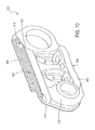
- Fig. 1 shows these undercarriage assembly components in a representative section of an endless track 100 for a track-type machine, i.e., a crawler tractor (not shown).
- Each section of the endless track 100 is a pair of track chain links 102 fastened together with a track pin bushing 104 at one end and a track pin 106 at the other end.
- the track pin 106 fits inside the track pin bushing 104 to hold the next pair of track chain links 102.
- Both the track pin 106 and the track pin bushing 104 are typically "press fit" into the track chain links 102 so the section does not work apart during the service life of the endless track 100.
- One track pin on each endless track 100 is held in by a snap ring 110 to allow removal and separation of the endless track 100, for example, when performing repairs or maintenance of the endless track 100.
- the undercarriage assembly components for track-type machines such as track chain bottom rollers, track chain links, track pin bushings, track pins, and track pin and bushing joints in endless tracks are subjected to very severe operating environments. For example, debris, soil, rocks and so forth can enter the endless track and undercarriage of a track-type machine, such as a crawler tractor, during operation. These materials can subsequently accumulate between the engaging surfaces of the undercarriage assembly components and engaging surfaces of the drive equipment, pack into the area between them and/or directly grind, wear, pit, scratch or crack the surface of the undercarriage assembly components. An endless track that is adjusted too tight can increase friction and cause accelerated wear to undercarriage assembly components, such as track pins and track pin bushings.
- undercarriage assembly components such as track pins and track pin bushings
- a too loose track can allow drive sprocket teeth to jump links, especially in reverse, causing wear to undercarriage assembly components such as the teeth and the track pin bushings, track chain bottom rollers, and so forth.
- Undercarriage assembly components are subject to wear.
- there are two types of wear on track pins and track pin bushings - external wear and internal wear.
- External wear takes place on the outer diameter of the track pin bushings in the area contacted by the drive sprocket teeth. This contact area is about 1/3 or more of the surface of the track pin bushing and occupies the majority of the center length of the track pin bushing. Wear occurs on the outside diameter of the track pin and the inside diameter of the track pin bushing.
- internal wear can occur on the outside diameter of the ends of the track pin bushings.
- Current track pins and track pin bushings are typically formed from materials that are hardened to decrease wear and increase service life.
- current track pins are case hardened by carburizing the alloy and then quenching.
- these materials and methods still result in a relatively short service life.
- current track pins and track pin bushings are either turned or replaced to present a new wear surface to the sprocket and consequently extend service life. See, for example, Louis R. Hathaway, Ed., "Tires and Tracks, Fundamentals of Service", Moline, IL: Deere and Company, 1986, pp. 47-67 .
- track pins and track pin bushings must be turned prior to being worn past the wear limit, or they will not be serviceable. Thus, frequent inspection and maintenance of track pins and track pin bushings occurs to identify and ameliorate components that have worn, resulting in the associated down time of equipment and personnel.
- pin and bushing joints are widely used as hinges between two machine members in various types of machinery such as heavy equipment including tractors, construction, forestry and mining equipment.
- the pin and bushing joint while serving as a hinge is also required to serve as a loaded bearing during relative motion between the two machine members connected to the joint.
- Such a joint by virtue of its location on the machine and depending on the type of machine, is exposed to a dusty environment.
- the dust from this environment which is mostly fine sand particles, enters into the space between the pin and the bushing and causes accelerated wear of the pin and the bushing mating surfaces and thus reduces the joint life. This then makes it necessary to replace the joint frequently even with frequent daily or weekly changing of the lubricant.
- the accelerated wear due to sand particles is due to the higher hardness of sand as compared to the hardness of the pin and bushing surfaces.
- mating surfaces which are the outer surface of the track pin and the bore surface of the track pin bushing, are case carburized and the parts are then quenched and tempered to obtain a high hardness on the surfaces.
- These high-hardness surfaces are more resistant to abrasion by fine sand particles (which travel from the outside environment into the clearance between the track pin and the track pin bushing) than if they were not carburized. This leads to a longer life of the track pin and bushing joint.
- the surface hardness obtained by this method of carburizing and quenching is only about 60 to 62 HRC which is much less than the hardness of the sand particles and therefore the technique provides only a limited pin and bushing wear protection and life extension.
- track chain links that form a component of the undercarriage assembly are subjected to severe wear and corrosion. Wear is caused by continuous contact with track chain bottom rollers which themselves are hardened. The wear rate is enhanced due to abrasive action of dry sand and wet sand slurry and other hard materials such as rocks, trapped between the link and roller contact surfaces. The wear problem is further aggravated due to the fact that sand is much harder than even the hardened steel, and wear of track chain links cannot be substantially reduced by simply hardening the contact surface. Therefore a solution other than heat treatment is required to reduce wear rate to prolong the life of the track chain link substantially.
- the current method involves hot forging medium carbon steel containing various amounts of boron, manganese, chromium and others, machining mating surface and induction hardening select surfaces.
- Hard-facing is often done by fusing a powdered, hard metal alloy onto a metal surface.
- metal parts subject to wear can be case hardened to improve wear resistance.
- application of current wear-resistant coatings prior to carburizing results in oxidation of the wear-resistant coating during subsequent carburizing with an adverse impact on the wear-resistant properties of the coating. Accordingly, longer wearing surfaces on undercarriage assembly components of endless tracks used in track-type machines, such as track pin bushings, are desired to extend the service life and to reduce the long-term maintenance cost associated with endless tracks.
- a method of producing such a longer wearing surface by coating with a wear-resistant alloy while still obtaining a desired wear resistance of the uncoated portions of the component by other suitable means, i.e., case hardening, and in particular, by induction hardening is desirable.
- the components, both the undercarriage assembly components and the hinge joint components, of these machines are required to be in intimate contact with wet sand and mud continuously during the machine operation.
- This corrosion cannot be reduced by hardening the steel.
- Any other superficial surface treatment of track chain bottom rollers such as carburizing, nitriding or other conventional surface treatment methods are not cost effective or adequate against a highly wear- and corrosion-prone environment which the track chain bottom rollers face during service.
- a more expensive material such as a highly alloyed steel or other advanced material, cannot be used since such a substitution would substantially increase cost without a corresponding increase in performance, and cannot be an acceptable solution.
- U.S. Patent 6,414,258 discloses a method of applying beads of hard material to sprocket teeth and bushings of a base carrier for a tracklaying vehicle.
- the beads are applied sequentially by weld overlays (an obviously slow process) and produce a sinusoidal type surface which is detrimental to the mating part such as the track chain link. Because of the bead nature of the deposit, it takes a substantial time to generate a smoother surface by initial wear. Before this smooth wear surface is produced, the deposited contact surface can cause damage to the mating link surface.
- the present invention provides an undercarriage assembly component for a track-type machine.
- the component has a body of non-carburized hardened steel comprising a wear surface.
- a metallurgically bonded wear-resistant coating is disposed on at least a portion of the wear surface.
- the wear-resistant coating comprises a fused hard metal alloy comprising at least 60% by weight of iron, cobalt, nickel, or alloys thereof and having a Vickers hardness greater than 950 HV.
- the method comprises the steps of (i) coating at least an exposed area of a non-carburized steel body with a slurry comprising a fusible, hard metal alloy with at least 60% by weight of iron, cobalt, nickel, or alloys thereof in the form of a finely divided powder, polyvinyl alcohol, a suspension agent, and a deflocculant, (ii) forming a metallurgical bond between the exposed area and the coating slurry to form a wear-resistant coating, and (iii) hardening the coated body.
- the parts to be coated as described above are formed from non-carburized, medium carbon alloy steel. Such a procedure avoids the need to (a) carburize the steel part prior to coating, and (b) remove a portion of the resulting high carbon steel surface to allow adequate metallurgical bonding to the coating, as is described in U.S. Patent No. 6,948,784 . This results in a more streamlined, more efficient, lower cost production process, while still producing parts with desirable and acceptable properties.
- the wear-resistance coating has a Vickers Hardness of greater than 950 HV, more particularly, from 950 HV to 1250 HV.
- the part can be through-hardened and/or case hardened by induction hardening using techniques known in the art.
- induction hardening produces a wear-resistant layer of steel having a hardness of 55 to 60 HRC over the surface of the part, and in a layer below the metallurgically bonded wear-resistant coating.
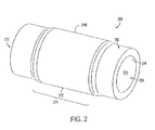
- the undercarriage assembly component is formed by a track pin bushing 200 having a metallurgically bonded wear-resistant coating 212.
- the track pin bushing 200 cooperates with a track pin (not shown) in an endless track of a track-type machine, such as a crawler tractor.
- the track pin bushing 200 has a tubular body 216 formed of non-carburized iron-based alloy, at least a section of which is case hardened, i.e., the outer surface, the inner surface, the ends, or portions or combinations thereof have been hardened following coating of at least a part of the surface.
- the track pin bushing 200 has an outer surface 202 having an outer diameter and an inner surface 204 having an inner diameter.
- the inner diameter defines the circumference of an axial bore 206 extending from the first end 208 to the second end 210 of the track pin bushing 200.
- the wear-resistant coating 212 is disposed on and metallurgically bonded to a portion 214 of the track pin bushing 200. This wear-resistant coating has been applied prior to hardening, so that the coating is applied to a non-carburized surface of the iron-based alloy.
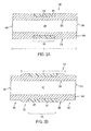
- a hard-faced track pin bushing 300 has an outer surface 310 with a uniform, i.e., non-varying, outer diameter. At least a portion 316 of the outer surface 310 of body 340 has been case hardened, e.g., induction hardened, following coating with a wear-resistant coating.
- the track pin bushing 300 has an inner surface 302 having an inner diameter that defines the circumference of an axial bore 304 extending from the first end 306 to the second end 308 of the track pin bushing 300.
- the outer surface 310 has an outer diameter that is uniform along the axial length L of the track pin bushing 300.
- a wear-resistant coating 312 is metallurgically bonded to a non-carburized surface 314.
- a hard-faced track pin bushing 318 has an outer surface 328 with a non-uniform, i.e., varying, outer diameter. At least a portion of the outer surface 328 of body 342 has been case hardened, e.g., induction hardened.
- the track pin bushing 318 has an inner surface 320 having an inner diameter that defines the circumference of an axial bore 322 extending from the first end 324 to the second end 326 of the track pin bushing 318.
- the outer surface 328 has at least one first section 330 with a first outer diameter and at least one second section 332 with a second outer diameter.
- the second section 332 is a central portion between first sections 330 which are located at both the first end 324 and the second end 326.
- the second outer diameter is greater than the first outer diameter resulting in the second section 332 protruding from the track pin bushing 318 over an axial length L'.
- a wear-resistant coating 334 is disposed on and metallurgically bonded to a non-carburized layer 336 in at least a portion 338 of the second section 332.
- the exposed non-carburized layer 314, 336 and thus the wear-resistant coating 312, 334 disposed therein and bonded thereto extends over a portion of the outer surface 310, 328 that corresponds to at least the contact surface adapted to engage with a drive sprocket in the endless track of a track-type machine.
- the exposed layer 314, 336 is formed in an annular groove or other well or cavity-like feature in the surface of the body 340, 342, so that the coated surface is flush with the non-coated surface.
- the coated layer need not be limited to such a groove or well, and can be any shape or form as long as the coated portion of the part contains a non-carburized surface to which the wear-resistant coating can fuse by a metallurgical bond.
- the coating can be applied to a grooved surface or a well that has been formed in a non-carburized metal piece, or can be formed over the entire surface of the non-carburized metal piece. Either approach can provide a coated surface without significant ridges or other discontinuities, i.e., can provide a smooth surface, without the need to carburize, then remove carburized material to form a groove or well, then coat the non-carburized layer, if such a smooth surface is desired.
- the wear-resistant coating extends over a majority of an axial length of the track pin bushing. In other aspects, the wear-resistant coating extends over an axial length corresponding to the contact surface for the particular application, i.e. for the particular track-type machine, and may be a minority length, an end or plurality of ends, a groove or plurality of grooves, and so forth, as readily discernible by those of ordinary skill in the art.
- the wear-resistant coating has an outer surface flush with the outer surface of the track pin bushing, as shown in Fig. 3A .
- the wear-resistant coating has an outer surface that is not flush with the outer surface but extends beyond the outer surface to provide a raised coating or recedes into the outer surface to provide a recessed coating.
- the thickness of the wear-resistant coating determines the wear life of the track pin bushing and can be any desired thickness, with a thicker coating promoting a longer wear life. In an exemplary embodiment, the wear-resistant coating has a thickness of approximately 1 to 2 mm.
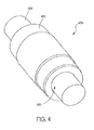
- the undercarriage assembly component is formed by separate components of a track pin and bushing joint 400 having a metallurgically bonded wear-resistant coating.
- the assembled track pin and bushing joint 400 includes a track pin bushing 402 with a track pin 404 inserted in a bore 406 of the track pin bushing 402.
- Fig. 5 shows a schematic perspective view of the disassembled track pin bushing joint 400 of Fig. 4 showing areas of the track pin bushing 402 and the track pin 404 having hard-facing applied.
- the exemplary track pin bushing joint 400 e.g., the track pin and bushing joint of an endless track of a track-type machine, comprises the track pin bushing 402 including an outer surface 410 having an outer radius R' and including an inner surface 412 having an inner radius r', and the track pin 404 including an outer surface 414.
- a portion 420 of the outer surface 414 of the track pin 404 substantially conforms to a portion 422 of the inner surface 412 of the track pin bushing 410 to form a wear surface that has a metallurgically bonded, wear-resistant coating.
- the wear-resistant coating comprises a fused hard metal alloy comprising at least 60% by weight iron, cobalt, nickel or alloys thereof.
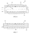
- Fig. 6 shows a schematic cross-section of the hard-faced track pin bushing 402 of Fig. 5 .
- Outer surface 410 having outer radius R' and inner surface 412 having inner radius r'.
- the portion 422 of the inner surface 412 of the track pin bushing 410 contributing to forming the wear surface is shown.
- the portion 422 is shown as a channel 424 in a body 426 of the track pin bushing 410 that has been filled with the metallurgically bonded, wear-resistant coating 428 and optionally machined to a desired surface position and roughness, e.g., machined level to the inner radius r'.
- the portion 422 can be any portion of the length of the bore 406, including the entire length, and metallurgically bonded, wear-resistant coating 428 can also optionally be applied directly to the inner surface 412 of the as-formed track pin bushing 410, without any premachining such as premachining to form the channel 424.
- the outer surface of the track pin bushing 402, such as outer surface 410 in Fig. 6 can also be hard-faced along the entire area or a portion of the area using a similar metallurgically bonded, wear-resistant coating.
- Fig. 7 shows a schematic cross-section of the hard-faced track pin 404 of Fig. 5 . Also, the portion 420 of the outer surface 414 of the track pin 404 contributing to forming the wear surface is shown. The portion 420 is shown as a channel 430 in a body 432 of the track pin 404 that has been filled with metallurgically bonded, wear-resistant coating 434 and optionally machined to a desired surface position and roughness, e.g., machined level to the outer surface 414.
- the portion 420 can be any portion of the length of the track pin 404, including the entire length, and the metallurgically bonded, wear-resistant coating 434 can also optionally be applied directly to the outer surface 414 of the as-formed pin 404, without any premachining such as premachining to form the channel 430.
- the forged track pin bushing and the forged track pin are undercut by a small amount (generally 1 to 2 mm depending on the thickness of wear coating required) in the vicinity of the portions of the track pin bushing and track pin which come in contact in the track pin and bushing joint, e.g., the wear surfaces, and a slurry coating is applied to the machined surface to a thickness such that, when fused, the slurry surface would coincide with the desired surface, i.e., the surface obtained before undercutting.
- the fused slurry coating forms a strong metallurgical bonding and does not spall off the steel substrate even on heating and cooling, as in the hardening process or when subjected to severe impact loads during service.
- the undercarriage assembly component is formed by a track chain bottom roller 500 having a metallurgically bonded wear-resistant coating.
- An outer surface 502 of the track chain bottom roller 500 has substantially cylindrical regions 504 bounded axially outwardly by flange portions 506. At least one flange portion 506 is of greater diameter than the substantially cylindrical regions 504.
- Mounting surfaces 508 for installation in an endless track of a track-type machine are also shown.
- the substantially cylindrical regions 504 are adapted to contact a contact surface of a track chain link, e.g., the upper rail surface of the track chain link as seen, for example, in the portion of the endless track of a track-type machine shown in Fig. 1 .
- some or all of the substantially cylindrical regions 504 and the flange portions 506 are subjected to wear and, therefore, some or all of the substantially cylindrical regions 504 and for the flange portions 506 have hard-facing applied thereto.
- Fig. 9 shows a schematic cross-section of the hard-faced track chain bottom roller 500 of Fig. 8 .
- Portions 520 of the substantially cylindrical regions 504 and the flange portions 506 have a metallurgically bonded, wear-resistant coating 522 and 540 comprising a fused hard metal alloy comprising at least 60% by weight iron, cobalt, nickel or alloys thereof.
- Two variations A and B for the portions 520 are shown in Fig. 9 , although multiple variations including those not shown may be used.
- the portions 520 having the metallurgically bonded, wear-resistant coating 522 are shown as a channel 530 in a body 532 of the substantially cylindrical regions 504.
- the channels 530 have been filled with the metallurgically bonded, wear-resistant coating 522 and optionally machined to a desired surface position and roughness, e.g., machined level to the outer surface 502 of the substantially cylindrical regions 504.
- the metallurgically bonded, wear-resistant coating 522 can also optionally be applied directly to the outer surface 502 of the as-formed track chain bottom roller 500, without any premachining such as premachining to form a deposit area, e.g, a channel 530.
- exemplary embodiments can include the metallurgically bonded, wear-resistant coating 522 at any portion of the substantially cylindrical regions 504, including the entire length of the outer surface of one or more of the substantially cylindrical regions 504. Further optionally, exemplary embodiments can include the metallurgically bonded, wear-resistant coating 540 at any portion of the flange portion 506, including the entire length of the outer surface of one or more of the flange portions 506.
- the metallurgically bonded, wear-resistant coating 540 can be a separate coating from the metallurgically bonded, wear-resistant coating 522 associated with the substantially cylindrical regions 504 (as shown in variation A), or the metallurgically bonded, wear-resistant coating on the flange can be continuous, at least at the outer surface 502, with the metallurgically bonded, wear-resistant coating 522 associated with the substantially cylindrical regions 504 (as shown in variation B).
- the metallurgically bonded, wear-resistant coating 540 can also optionally be applied directly to the outer surface 502 of the as-formed track chain bottom roller 500, without any premachining such as premachining to form a deposit area, e.g, a channel 542.
- the track chain bottom roller is undercut by a small amount (generally 1 to 2 mm depending on the thickness of wear coating required) in the vicinity of the portions of the track chain bottom roller which come in contact with the track chain link, e.g., the wear surfaces such as portions of the substantially cylindrical regions and/or portions of the flange portion, and a slurry coating is applied to the machined surface to a thickness such that, when fused, the slurry surface would coincide with the desired surface, i.e., the surface obtained before undercutting.
- the fused slurry coating forms a strong metallurgical bonding and does not spall off the steel substrate even on heating and cooling, as in the hardening process or when subjected to severe impact loads during service.
- the undercarriage assembly component is formed by a track chain link 600 having a metallurgically bonded wear-resistant coating 622.
- Fig. 10 shows a schematic perspective view of a first side of the track chain link 600 showing areas having hard-facing applied.
- the track chain link 600 comprises a body 602 formed of hardened steel, a mounting surface 604 on a first edge 606 of the body 602 and a contact surface 608 on a second edge 610 of the body 602.
- the mounting surface 604 includes at least one opening 612 for an attachment device, e.g., an attachment device to permanently or removably affix the track chain link 600 to a shoe of an endless track of a track-type machine as shown, for example, in Fig. 1 .
- the contact surface 608 is opposite the mounting surface 604 and includes a substantially planar region 614 extending a distance along the second edge 610 forming a wear surface.
- At least portions of the wear surface e.g., portions 620 of the substantially planar region 614, have a metallurgically bonded, wear-resistant coating 622 comprising a fused hard metal alloy comprising at least 60% by weight iron, cobalt, nickel or alloys thereof.
- the portions 620 having the metallurgically bonded, wear-resistant coating 622 have a channel 630 in the body 602 of the track chain link 600.
- the channels 630 have been filled with the metallurgically bonded, wear-resistant coating 622 and optionally machined to a desired surface position and roughness, e.g., machined level to the substantially planar region 614.
- the metallurgically bonded, wear-resistant coating 622 can also optionally be applied directly to the outer surface of the as-formed track chain link 600, prior to core hardening, and without carburizing.
- the application can be done without any premachining such as premachining to form a deposit area, e.g, a channel 630.
- the forged link surface which comes in contact with the roller surface is undercut by a small amount (generally 1 to 2 mm depending on the thickness of wear coating required) and a slurry coating is applied to the machined surface to a thickness such that, when fused, the slurry surface would coincide with the desired surface, i.e., the surface obtained before undercutting.
- the fused slurry coating forms a strong metallurgical bonding and does not spall off the steel substrate even on heating and cooling, as in the hardening process or when subjected to severe impact loads during service.
- a slurry coated track chain link can optionally then be through hardened by quenching and tempered to the required bulk hardness for improving the mechanical strength of the track chain link.
- the substrate below the coated surface is optionally again hardened by induction hardening to increase the substrate hardness to HRC 50 to 60, more particularly, 55 to 60 HRC which is higher than the bulk hardness of the quenched and tempered link steel. This adds further to the wear life of the track chain link.
- the wear life of a coated and heat treated (by through-hardening and induction hardening) track chain link can be the sum of the wear life of the slurry coating and the wear life of the induction hardened steel substrate below the coating.
- the wear-resistant coating is a fused alloy that is substantially harder and more wear-resistant than the steel typically used for tools, gears, engine parts, farm implements, and so forth, e.g., 1045 grade steel even in the hardened conditioned.
- the wear-resistant coating preferably contains substantially no inclusions, such that the wear-resistant coating is uniformly dense and less brittle and more durable than that obtained in the prior work, such as Alessi, U.S. Pat. No. Re. 27,851 .
- the fusible hard metal alloy in the exemplary embodiments is preferably at least 60% of a transition metal of Group VIII of the Periodic Table, such as iron, cobalt, or nickel.
- the hard metal alloy may be based on other metals so long as the alloys have the physical properties stated above and would form a metallurgical bond with, in this case, the ferrous substrate.
- Minor components typically are boron, carbon, chromium, iron (in nickel and cobalt-based alloys), manganese, nickel (in iron and cobalt-based alloys), silicon, tungsten, molybdenum, one or more carbide forming elements, or combinations thereof. Elements in trace amounts (less than about 0.1 wt.%), such as sulfur, may be present as de minimis, contaminants.
- the alloy has a Vickers Hardness (HV) above 950 HV, and more particularly, from 950 to 1250 HV.
- the hard metal alloy has a fusion temperature which is lower than the melting point of the metal that is to be coated, e.g., about 1110°C or less, and is preferably, between about 900°C and about 1200°C, preferably up to about 1100°C.
- Methods for hard-facing with a wear-resistant coating a metal surface of a part formed from a non-carburized metal are provided.
- a slurry of a hard metal alloy is coated on an area of a non-carburized part and a metallurgical bond is formed between the non-carburized material and the coated unfused slurry by fusing the hard metal alloy, thereby forming the wear-resistant coating.
- an exemplary method prepares the surface of the metal part, i.e., the surface of a track pin bushing, by decarburizing the surface for a suitable period of time to reduce and, at long time periods, remove carbon from the surface of the metal part to a desired depth.
- decarburization occurs in the surface layer to a depth such that the subsequent metallurgical bond only occurs with non-carburized metal.
- decarburization of the carburized layer occurs to a depth of 0.002 to 0.003 inch (50 to 75 microns) to a carbon level of 0.4 to 0.6 wt.%.
- decarburization occurs to a depth of at least the thickness of the carburization layer plus 0.5 mm, i.e., to 3.0 mm for a typical track pin bushing that is carburized to a depth of 2.5 mm.
- the carburized depth is up to 0.010 inches and the decarburization occurs up to 0.015 inches.
- a metallurgical reaction between carbon and the slurry has been observed.
- carbon from the substrate diffuses into the coating, increasing the carbon content at the interface.
- the increased carbon at the interface depresses the melting point of the slurry alloy in the interfacial region, e.g., the interfacial layer between the slurry alloy and the substrate, resulting in the slurry alloy sloughing off the substrate.
- the above procedure wherein non-carburized material is exposed has been used.
- the surface of the substrate to which the slurry is applied is kept substantially horizontal, e.g., within 5 to 10° of horizontal, during fusing so as to minimize sloughing during the fusing time, e.g., during the several minutes at the fusing temperature (not including the temperature ramp-up and cool down time).
- the slurry is aqueous-based and can be formed of polyvinyl alcohol (PVA) and a fusible, hard metal alloy in the form of a finely divided powder.
- PVA polyvinyl alcohol
- a fusible, hard metal alloy in the form of a finely divided powder.
- the hard metal alloy can be a transition metal of Group VIII of the Periodic Table, such as iron, cobalt, nickel, or alloys thereof.
- the hard metal alloy is in the form of a finely divided powder having a sufficiently small particle size to form a uniform slurry. Typical particle sizes range from about 90 mesh to about 400 mesh and may be finer than 400 mesh.
- the average particle size is finer than about 115 mesh and, most preferably, finer than about 200 mesh.
- the powder can be a mixture of powders of different particle sizes.
- one or more suspension agents and one or more deflocculants can optionally be added to the slurry.
- the slurry used is prepared by thoroughly mixing the powdered, hard metal alloy with the polyvinyl alcohol binder solution to give the desired alloy to binder solution weight ratio, as described in commonly owned U.S. Patent No. 5,879,743 , the entire contents of which are incorporated herein by reference.
- Other additives to the slurry can include suspension agents and deflocculants.
- the slurry can be applied in any suitable manner.
- the slurry can be spray coated, spun cast, dipped, poured, or spread, i.e., applied with a brush or a doctor blade.
- a substantially uniform aqueous slurry of polyvinyl alcohol and a fusible, hard metal alloy in the form of a finely divided powder is formed and coated on the metal surface.
- the aqueous slurry is then dried, preferably by applying external heat, to leave a solid layer of the fusible, hard metal alloy in a polyvinyl alcohol matrix on the metal surface.
- the steps of coating the metal surface and drying the slurry to leave a solid layer may be repeated one or more times to build up a thicker coating of the slurry material.
- the metal surface is coated with an aqueous polyvinyl alcohol solution and a substantially uniform layer of a fusible, hard metal alloy in the form of a finely divided powder is distributed onto the coating of the polyvinyl alcohol solution before the polyvinyl alcohol solution dries.
- the steps of coating the metal surface, distributing the fusible hard metal alloy, and drying the mixture of polyvinyl alcohol, binder and alloy powder to leave a solid layer may be repeated one or more times to build up a thicker coating of the slurry material.
- the preferred procedure for applying a slurry to the metal surface to be coated depends on the shape and size of the metal part having the metal surface as well as the ratio of hard metal alloy and the concentration of the polyvinyl alcohol binder solution.
- the unfused slurry is poured, brushed, or sprayed on the metal surface to be protected, or the part having the metal surface to be protected can be dipped into the unfused slurry.
- Dipping, pouring, and brushing is useful for forming relatively thick coatings, e.g., greater than 1 mm, in a short period of time, although repeated spaying can also be used to build up a thick layer over a longer period of time.
- the ratio of hard metal alloy to PVA solution is in the range of about 4:1 to about 8:1 and the concentration of PVA solution is about 1 % to about 15% PVA by weight.
- 0500/0250 and 0600/0250 or similar slurries are suitable for this procedure.
- the ratio of alloy to PVA solution is in the range of about 8:1 to about 15:1 by weight and the concentration of PVA solution is about 2% to about 15% PVA by weight.
- special additives can function as dispersants, suspending agents, and plasticizers.
- paste and tape methods can be used for thick coatings.
- these procedures are difficult to adapt to a high speed production environment.
- a reliable and economical alternative to paste and tape is a multiple coating procedure which produces uniformly thick slurry coatings even on large surfaces.
- the required thickness can be built by repeated spraying with intervening drying cycles. The drying may be done at about 80°C to about 100°C, for example, in a forced circulation air oven. A 0500/0250 slurry is particularly suitable for this method, though other formulations may be used.
- the thickness of the coated unfused slurry can be adjusted by a shrinkage factor to result in a desired final thickness after metallurgical bonding, i.e., the final thickness can be flush to the surface or diameter, protruding from, or recessed into the surface diameter of the metal piece.
- the slurry described herein was found to have a shrinkage factor of about 0.55 ⁇ 0.05. Accordingly, the thickness of the slurry before fusing can be adjusted according to the shrinkage factor to result in a desired final thickness of the wear-resistant coating, e.g. an unfused slurry layer of 1.67 to 2.0 times the final thickness is used.
- Bonding is the step of forming a metallurgical bond between the dried slurry coating and the metal part, i.e., a selected portion of the non-carburized metal part, or a selected portion of the metal part that has been decarburized.
- the metal surface coated with the layer of fusible, hard metal alloy in the polyvinyl alcohol matrix or coated with the aqueous polyvinyl alcohol solution with the layer of fusible, hard metal alloy can be heated to the fusing temperature of the hard metal alloy under a protective atmosphere until the hard metal alloy has fused onto the metal surface. Heating occurs in a controlled atmosphere, i.e., an inert or reducing atmosphere, excluding nitrogen which nitrides the alloy and can hinder alloy fusion.
- a partial pressure of He or Ar in a vacuum furnace or a slight positive pressure of about a few inches of water above atmospheric pressure of Ar, He or H 2 in a belt furnace are suitable for use during fusing. Subsequently, the metal surface with the fused hard-facing is cooled to ambient temperature.
- the track pin bushing is heated to a temperature of about 1065°C to 1110°C.
- the heating is done in a belt type conveyor furnace at a hydrogen pressure slightly above atmospheric, and the track pin bushing is held at the desired fusing temperature for approximately 2 to 5 minutes and then cooled.
- the remaining metal of the metal part can be hardened to a desired hardness by quenching.
- the remaining carburized metal can be hardened by a thermal treatment that increases hardness as compared to the non-carburized metal.
- the remaining metal corresponds to at least one of the inner surface of the track pin bushing, the first end of the track pin bushing, and/or the second end of the track pin bushing.
- decarburization can be used prior to slurry coating to improve bonding results.
- the decarburization process has at least two disadvantages: Decarburization on a partial surface (for example, only on an outer diameter and not on an inner diameter and/or the end faces) is not practical, and the time required for sufficient decarburization to occur, i.e., for an adequate non-carburized layer to form on which to coat the unfused slurry is upwards of several hours, perhaps as long as 7 to 10 hrs, which can be economically unviable.
- the coating process can desirably be carried out on a material prior to any carburization, as described more fully herein.
- carburized material is removed by, for example, machining, cutting, lathing, grinding, and or polishing, to expose a non-carburized layer.
- four track pin bushings had their outer diameters reduced by machining. The amounts removed were 3.00, 3.35, 3.75, and 4.00 mm, respectively.
- the samples were then coated in the exposed area with a hard metal slurry and bonded following the procedures outlined above.
- the unfused slurry surface was then machined on a lathe to make it smooth and concentric with the bore of the track pin bushing.
- Slurry thickness before fusing was adjusted to yield 1 mm or 1.5 mm fused thickness, based on the shrinkage factor, i.e., the empirically derived relationship that the fused thickness is about 0.55 times the unfused thickness. This machining operation, as was found after fusing, also helped produce a coating with a smooth surface and uniform thickness.
- the track pin bushings with machined and cooled surfaces were fused using a suitable time-at-temperature (T-t) cycle.
- the T-t cycle is conducted in a vacuum furnace or a belt furnace under a controlled atmosphere, i.e., an inert or reducing atmosphere, excluding nitrogen which nitrides the alloy.
- a controlled atmosphere i.e., an inert or reducing atmosphere, excluding nitrogen which nitrides the alloy.
- a partial pressure of He or Ar in a vacuum furnace or a slight positive pressure, i.e., about a few inches of water above atmospheric pressure, of Ar, He or H 2 in a belt furnace are good examples.
- the track pin bushings were placed with the axes vertical in the furnace chamber, and the maximum temperature and the time at maximum temperature were carefully selected and monitored to prevent downward gravity flow of fused semi-liquid slurry metal.
- An example of a suitable T-t cycle is as follows: Gradually heat the track pin bushing at 10 to 15°C per minute to 1080 to 1110°C, hold the temperature for 1 to 5 minutes, preferably 1 to 2 minutes, and cool the track pin bushing at any desired cooling rate, i.e., using a recirculating fan.
- a still further example of a suitable T-t cycle heats the track pin bushing at 8 to 10°C per minute to 1065 to 1110°C.
- the wear resistance was also evaluated for the wear-resistant coatings used for track pin bushings. Rubber wheel-sand abrasion tests revealed that the fused slurry coating wears at about 1/4th to 1/6th the rate of quenched 1080 steel. Thus, a 1/3 to 1/2 mm fused slurry displayed, as a first approximation, the wear equivalent to a 2 to 3 mm thick layer of hardened 1080 steel.
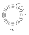
- R 1 R - X + Y + 0.5
- R 2 R - X
- R 3 R + 0.82 ⁇ X
- R 1 is the outer radius of the track pin bushing as carburized
- R 3 is the outer radius of the track pin bushing after slurry coating and before fusing
- Equations 1 to 3 give the outer radius R 1 of the carburized track pin bushing, the outer radius R 2 after machining and the outer radius R 3 after slurry coating but before fusing, respectively, in terms of final track pin bushing outer surface radius R, if values of thickness of fused slurry layer, X, and carburized depth, Y, are known.
- the coating process can desirably be carried out on a steel material prior to or without any carburization.
- the non-carburized part and then hardening by e.g., induction hardening, the need to decarburize or to machine parts to remove carburized material, are eliminated.
- the coating can be applied to, e.g., a medium carbon alloy steel.
- a coating layer having a Vickers hardness of greater than 950 HV is obtained.
- the undercarriage assembly component having a metallurgically bonded wear-resistant coating is a track pin and bushing joint and the separate components of a track pin and bushing joint, e.g., a track pin and an inner diameter of a track pin bushing.
- Fig. 4 shows a schematic perspective view of an assembled track pin and bushing joint including a track pin bushing with a track pin inserted in the bore.
- Fig. 5 shows a schematic perspective view of a disassembled track pin and bushing joint.
- a track pin and bushing joint has mating surfaces including an outer surface of the pin and the inner diameter surface (or bore surface) of the track pin bushing.
- the bore surface of the track pin bushing and outer surface of the track pin are provided with a coating harder than sand using the following steps:
- the coating can be applied to any thickness desired unlike many other coatings or platings. This gives the freedom to apply thicker coatings to correspondingly increase the joint life.
- the latest hard coatings such as thin films applied using physical vapor deposition (3 to 5 microns) or chemical vapor deposition (10 to 25 microns), or electroplating of chrome (5 to 50 microns) or electroless nickel plating (2 to 20 microns), or practical thicknesses, have thickness limitations and are therefore not suitable for, e.g., long life track pin and bushing joints deployed in the heavy equipment industry.
- Slurry coating can be easily applied to bores of long bushings without the line-of-sight limitations associated with PVD and thermal spray processes.
- the coating technology permits the parts to be heat treated after the coating is fused without detriment to coating or its bond to the substrate. Most other surface coatings will be destroyed during such heat treatment.
- This coating process has no environmental restrictions unlike hard chrome plating.
- the alloy composition is chosen such that the fused coating has a hardness much higher than that of sand particles.
- an alloy powder is used which gives a coating with a hardness of 800 to 1100 HV which is much higher than the hardness of sand particles (with an average hardness value of about 700 to 800 HV).
- the sand particles which seep into the track pin and bushing joint do not cause the same extent of abrasion damage that the same sand particles would do to a carburized and quenched surface of currently used track pin and bushing joints. It is more likely the very fine sand particles will tend to polish the coating surface rather than abrade it severely.
- the bushings with machined "green” coating were placed with their axes vertical, in a belt type hydrogen furnace and the coating was fused without any difficulty; the fused coating did not flow down the steel surface (substrate) due to gravity and also it did not shrink away from the steel.
- the as-fused surface of the coating was smooth.
- the fused coating thicknesses varied from 1.30 to 1.875 mm depending on the "green" thicknesses selected.
- a substantially uniform aqueous slurry of polyvinyl alcohol and a fusible, hard metal alloy in the form of a finely divided powder is formed and coated on the metal surface.
- the aqueous slurry is then dried, preferably by applying external heat, to leave a solid layer of the fusible, hard metal alloy in a polyvinyl alcohol matrix on the metal surface.
- the steps of coating the metal surface and drying the slurry to leave a solid layer may be repeated one or more times to build up a thicker coating of the slurry material.
- the metal surface is coated with an aqueous polyvinyl alcohol solution and a substantially uniform layer of a fusible, hard metal alloy in the form of a finely divided powder is distributed onto the coating of the polyvinyl alcohol solution before the polyvinyl alcohol solution dries.
- the steps of coating the metal surface, distributing the fusible hard metal alloy, and drying the slurry or the solution coating to leave a solid layer may be repeated one or more times to build up a thicker coating of the slurry material.
- the preferred procedure for applying a slurry to the metal surface to be coated depends on the shape and size of the metal part having the metal surface as well as the ratio of hard metal alloy and the concentration of the polyvinyl alcohol binder solution.
- the unfused slurry is poured, brushed, or sprayed on the metal surface to be protected, or the part having the metal surface to be protected can be dipped into the unfused slurry.
- the coated metal part can be quenched to harden the steel, for example, by heating to about 840°C for a 1045 steel and soaking at the quenching temperature, in this case 840°C, for a time period which depends on the mass and wall thickness of the part, and quenching in a suitable quenching medium, preferably a liquid.
- the quenched steel part can be tempered at the desired temperature between 250°C and 500°C to achieve the required bulk hardness for improving the mechanical strength of the metal part and improving the wear resistance of the body of the metal part.
- the substrate below the coated surface may optionally again be hardened by induction hardening, if necessary, to increase the substrate hardness to approximately HRC 55 to 60 or more, which is higher than the bulk hardness of the quenched and tempered part.
- This higher hardness of the coating substrate adds further to the wear life of the metal part and/or wear surfaces of the metal part such as a track chain bottom roller contact surface or a track chain link contact surface.
- the wear life of a coated and heat treated (by through-hardening followed by induction hardening) metal part is the sum of the wear life of the slurry coating and the wear life of the induction hardened steel substrate below the coating.
- This sum may be 4 to 6 or more times that of the uncoated and quenched metal part depending upon the wear and/or corrosion objectives.
- macroscopic surface cracks tend to form in the coating during the through hardening and induction hardening process, the coating does not detach itself from the substrate. This is due, at least in part, to the strong metallurgical bonding of the coating to the substrate. The cracks help to relieve stresses formed during fusing of the coating. However, such cracks are not generally observed if the coated part is not heat treated (quenched).
Landscapes
- Engineering & Computer Science (AREA)
- Chemical & Material Sciences (AREA)
- Mechanical Engineering (AREA)
- Combustion & Propulsion (AREA)
- Transportation (AREA)
- Materials Engineering (AREA)
- Chemical Kinetics & Catalysis (AREA)
- Metallurgy (AREA)
- Organic Chemistry (AREA)
- Heat Treatment Of Articles (AREA)
- Solid-Phase Diffusion Into Metallic Material Surfaces (AREA)
- Coating By Spraying Or Casting (AREA)
- Other Surface Treatments For Metallic Materials (AREA)
- Connection Of Plates (AREA)
Abstract
Description
- The present invention relates to an undercarriage assembly component for a track-type machine, such as a track chain bottom roller, track chain link, track pin bushing, track pin, and track pin and bushing joint, which are made of non-carburized steel having a wear-resistant coating metallurgically bonded thereto. Furthermore the invention relates to a method for producing such an undercarriage assembly component.
-
Fig. 1 shows these undercarriage assembly components in a representative section of anendless track 100 for a track-type machine, i.e., a crawler tractor (not shown). Each section of theendless track 100 is a pair oftrack chain links 102 fastened together with a track pin bushing 104 at one end and atrack pin 106 at the other end. Thetrack pin 106 fits inside the track pin bushing 104 to hold the next pair oftrack chain links 102. Both thetrack pin 106 and the track pin bushing 104 are typically "press fit" into thetrack chain links 102 so the section does not work apart during the service life of theendless track 100. One track pin on eachendless track 100, the so-calledmaster pin 108, is held in by asnap ring 110 to allow removal and separation of theendless track 100, for example, when performing repairs or maintenance of theendless track 100. Atrack shoe 112, having a desired grip orgrouser 114 determined by the environment of intended use (e.g., clay, slit, loam, gravel, snow, mud, or hard surfaces) is bolted to each section to provide traction. - The undercarriage assembly components for track-type machines, such as track chain bottom rollers, track chain links, track pin bushings, track pins, and track pin and bushing joints in endless tracks are subjected to very severe operating environments. For example, debris, soil, rocks and so forth can enter the endless track and undercarriage of a track-type machine, such as a crawler tractor, during operation. These materials can subsequently accumulate between the engaging surfaces of the undercarriage assembly components and engaging surfaces of the drive equipment, pack into the area between them and/or directly grind, wear, pit, scratch or crack the surface of the undercarriage assembly components. An endless track that is adjusted too tight can increase friction and cause accelerated wear to undercarriage assembly components, such as track pins and track pin bushings. In an extreme case, severely tight track adjustment can cause the endless track to run extremely hot and "draw-back" the hardness of undercarriage assembly components, such as track pins and track pin bushings, i.e., heat treat the components resulting in a reduction in the components' hardness, and even cause the track pins and track pin bushings to fuse together. At the other end of the spectrum, a too loose track can allow drive sprocket teeth to jump links, especially in reverse, causing wear to undercarriage assembly components such as the teeth and the track pin bushings, track chain bottom rollers, and so forth.
- Undercarriage assembly components are subject to wear. For example, there are two types of wear on track pins and track pin bushings - external wear and internal wear. External wear takes place on the outer diameter of the track pin bushings in the area contacted by the drive sprocket teeth. This contact area is about 1/3 or more of the surface of the track pin bushing and occupies the majority of the center length of the track pin bushing. Wear occurs on the outside diameter of the track pin and the inside diameter of the track pin bushing. Additionally, where the track pin bushings are fitted into the track link counterbores, internal wear can occur on the outside diameter of the ends of the track pin bushings. Thus, current track pins and track pin bushings in endless tracks experience wear and stress which can negatively impact the service life of the track pin bushing.
- Current track pins and track pin bushings are typically formed from materials that are hardened to decrease wear and increase service life. For example, current track pins are case hardened by carburizing the alloy and then quenching. However, these materials and methods still result in a relatively short service life. Thus, in addition to material selection for hardness and wear resistance, current track pins and track pin bushings are either turned or replaced to present a new wear surface to the sprocket and consequently extend service life. See, for example, Louis R. Hathaway, Ed., "Tires and Tracks, Fundamentals of Service", Moline, IL: Deere and Company, 1986, pp. 47-67. However, the track pins and track pin bushings must be turned prior to being worn past the wear limit, or they will not be serviceable. Thus, frequent inspection and maintenance of track pins and track pin bushings occurs to identify and ameliorate components that have worn, resulting in the associated down time of equipment and personnel.
- In addition, other pin and bushing joints are widely used as hinges between two machine members in various types of machinery such as heavy equipment including tractors, construction, forestry and mining equipment. The pin and bushing joint while serving as a hinge is also required to serve as a loaded bearing during relative motion between the two machine members connected to the joint. Such a joint, by virtue of its location on the machine and depending on the type of machine, is exposed to a dusty environment. The dust from this environment, which is mostly fine sand particles, enters into the space between the pin and the bushing and causes accelerated wear of the pin and the bushing mating surfaces and thus reduces the joint life. This then makes it necessary to replace the joint frequently even with frequent daily or weekly changing of the lubricant. The accelerated wear due to sand particles is due to the higher hardness of sand as compared to the hardness of the pin and bushing surfaces.
- In conventional track and pin bushing joints, mating surfaces, which are the outer surface of the track pin and the bore surface of the track pin bushing, are case carburized and the parts are then quenched and tempered to obtain a high hardness on the surfaces. These high-hardness surfaces are more resistant to abrasion by fine sand particles (which travel from the outside environment into the clearance between the track pin and the track pin bushing) than if they were not carburized. This leads to a longer life of the track pin and bushing joint. However, the surface hardness obtained by this method of carburizing and quenching is only about 60 to 62 HRC which is much less than the hardness of the sand particles and therefore the technique provides only a limited pin and bushing wear protection and life extension. The sand particles which enter into the clearance space between the track pin and the track pin bushing get mixed with the lubricating grease (which is injected into the clearance) and the effectiveness of the grease gradually diminishes. This makes it necessary to force out the grease from the joint clearance space frequently, sometimes daily, depending on the degree of joint seal effectiveness, and the environment in which the machine is working, to get the sand out of the joint. This frequent purging of grease helps increase the joint life to some extent. Nevertheless, this purging operation, if required to be done frequently, becomes time consuming and wasteful.
- Other current undercarriage assembly components are typically formed from materials that are hardened to decrease wear and increase service life. For example, current track chain bottom rollers are hardened by quenching. However, these materials and methods still result in a relatively short service life. The wear problem is aggravated because sand is much harder than even the hardened steel and wear of the track chain bottom roller cannot be substantially reduced by simply hardening the contact surface. Thus, frequent inspection and maintenance of track chain bottom rollers occurs to identify and ameliorate components that have worn, resulting in the associated down time of equipment and personnel. Similar efforts with similar limited results are known for other undercarriage assembly components.
- Also, for example, track chain links that form a component of the undercarriage assembly are subjected to severe wear and corrosion. Wear is caused by continuous contact with track chain bottom rollers which themselves are hardened. The wear rate is enhanced due to abrasive action of dry sand and wet sand slurry and other hard materials such as rocks, trapped between the link and roller contact surfaces. The wear problem is further aggravated due to the fact that sand is much harder than even the hardened steel, and wear of track chain links cannot be substantially reduced by simply hardening the contact surface. Therefore a solution other than heat treatment is required to reduce wear rate to prolong the life of the track chain link substantially.
- Also, due to the functional nature of the crawler and other construction and mining equipment, the undercarriage assembly components of these machines are required to be in intimate contact with wet sand and mud continuously. This causes the link surfaces to corrode, thus producing a synergistic effect on wear. This corrosion cannot be reduced by hardening the steel. Any other superficial surface treatment of links, such as carburizing, nitriding or other conventional surface treatment methods, are not cost effective against the wear-and corrosion-indicated that environment that the links face during service. A more expensive material, such as a highly alloyed steel or other advanced material, therefore does not constitute used since such a substitution would substantially increase cost and cannot be an acceptable solution.
- A solution to the problem which can reduce both wear and corrosion and also which can be applied in a production environment and at a low cost, is required.
- A change in the current manufacturing process of undercarriage assembly components is proposed. The current method involves hot forging medium carbon steel containing various amounts of boron, manganese, chromium and others, machining mating surface and induction hardening select surfaces.
- Coating a metal surface with another metal or metal alloy to enhance appearance, protect against corrosion, or improve resistance to wear is often referred to as "hard-facing" or "hard surfacing". For example, see
Alessi U.S. Pat. No. Re. 27,851 ,Revankar U.S. Pat. No. 5,027,878 andNo. 5,443,916 ,Brady, et al., U.S. Pat. No. 4,682,987 , andHill U.S. Pat. No. 5,456,323 . - Hard-facing is often done by fusing a powdered, hard metal alloy onto a metal surface. In endless track applications, metal parts subject to wear can be case hardened to improve wear resistance. However, application of current wear-resistant coatings prior to carburizing results in oxidation of the wear-resistant coating during subsequent carburizing with an adverse impact on the wear-resistant properties of the coating. Accordingly, longer wearing surfaces on undercarriage assembly components of endless tracks used in track-type machines, such as track pin bushings, are desired to extend the service life and to reduce the long-term maintenance cost associated with endless tracks. Further, a method of producing such a longer wearing surface by coating with a wear-resistant alloy while still obtaining a desired wear resistance of the uncoated portions of the component by other suitable means, i.e., case hardening, and in particular, by induction hardening is desirable.
- Also, due to the functional nature of the heavy machinery construction, mining and forestry type equipment, the components, both the undercarriage assembly components and the hinge joint components, of these machines are required to be in intimate contact with wet sand and mud continuously during the machine operation. This causes components such as the track chain bottom roller surfaces to corrode, thus producing a synergistic effect on wear due to abrasion. This corrosion cannot be reduced by hardening the steel. Any other superficial surface treatment of track chain bottom rollers such as carburizing, nitriding or other conventional surface treatment methods are not cost effective or adequate against a highly wear- and corrosion-prone environment which the track chain bottom rollers face during service. A more expensive material such as a highly alloyed steel or other advanced material, cannot be used since such a substitution would substantially increase cost without a corresponding increase in performance, and cannot be an acceptable solution.
- A solution to the problem which can reduce both wear and corrosion and also which can be applied in a production environment and at a low cost is required.
-
U.S. Patent 6,414,258 discloses a method of applying beads of hard material to sprocket teeth and bushings of a base carrier for a tracklaying vehicle. In this method, the beads are applied sequentially by weld overlays (an obviously slow process) and produce a sinusoidal type surface which is detrimental to the mating part such as the track chain link. Because of the bead nature of the deposit, it takes a substantial time to generate a smoother surface by initial wear. Before this smooth wear surface is produced, the deposited contact surface can cause damage to the mating link surface. - The method and component disclosed herein avoid or alleviate some or all of the problems of the prior art described above.
- It is further an object of this invention to provide a wear-resistant coating on at least a track pin bushing, track pin, track chain bottom roller, or other part of an endless track for a track-type vehicle.
- The present invention provides an undercarriage assembly component for a track-type machine. The component has a body of non-carburized hardened steel comprising a wear surface. A metallurgically bonded wear-resistant coating is disposed on at least a portion of the wear surface. The wear-resistant coating comprises a fused hard metal alloy comprising at least 60% by weight of iron, cobalt, nickel, or alloys thereof and having a Vickers hardness greater than 950 HV.
- Furthermore a method for producing such an undercarriage assembly component is provided. The method comprises the steps of (i) coating at least an exposed area of a non-carburized steel body with a slurry comprising a fusible, hard metal alloy with at least 60% by weight of iron, cobalt, nickel, or alloys thereof in the form of a finely divided powder, polyvinyl alcohol, a suspension agent, and a deflocculant, (ii) forming a metallurgical bond between the exposed area and the coating slurry to form a wear-resistant coating, and (iii) hardening the coated body.
- Desirably, the parts to be coated as described above are formed from non-carburized, medium carbon alloy steel. Such a procedure avoids the need to (a) carburize the steel part prior to coating, and (b) remove a portion of the resulting high carbon steel surface to allow adequate metallurgical bonding to the coating, as is described in
U.S. Patent No. 6,948,784 . This results in a more streamlined, more efficient, lower cost production process, while still producing parts with desirable and acceptable properties. Desirably, the wear-resistance coating has a Vickers Hardness of greater than 950 HV, more particularly, from 950 HV to 1250 HV. - Following metallurgical bonding of the wear-resistant coating, the part can be through-hardened and/or case hardened by induction hardening using techniques known in the art. The resulting induction hardening produces a wear-resistant layer of steel having a hardness of 55 to 60 HRC over the surface of the part, and in a layer below the metallurgically bonded wear-resistant coating.
- For a complete understanding of the objects, techniques, and structure of the invention reference should be made to the following detailed description and accompanying drawings, wherein similar components are designated by identical reference numerals:
- Fig. 1
- shows components of a typical endless track for a track-type vehicle includ- ing a track pin bushing,
- Fig. 2
- shows a schematic perspective view of a track pin bushing according to a first embodiment of the present invention,
- Fig. 3A
- shows a schematic axial cross-section of a hard-faced track pin bushing with an uniform outer diameter along its length according to a second embodi- ment of the present invention,
- Fig. 3B
- shows a hard-faced track pin bushing with an increased radius at a central portion according to a third embodiment of the present invention,
- Fig. 4
- shows a schematic perspective view of an assembled track pin and bushing joint including a track pin bushing with a track pin inserted according to a fourth embodiment of the present invention,
- Fig. 5
- shows a schematic perspective view of the disassembled track pin and bush- ing joint of
Fig. 4 showing areas having hard-facing applied, - Fig. 6
- shows a schematic cross-section of the hard-faced track pin bushing of
Fig. 5 , - Fig. 7
- shows a schematic cross-section of a hard-faced track pin of
Fig. 5 , - Fig. 8
- shows a schematic perspective view of a track chain bottom roller showing areas having hard-facing applied according to a fifth embodiment of the present invention,
- Fig. 9
- shows a schematic cross-section of the hard-faced track chain bottom roller of.
Fig. 8 , - Fig. 10
- shows a schematic perspective view of a first side of a track chain link show- ing areas having hard-facing applied according to a sixth embodiment of the present invention, and
- Fig. 11
- shows a radial cross-section schematic representation of the radius variation during the method of hard-facing a track pin bushing with a wear-resistant coating.
- In a first exemplary embodiment shown in
Fig. 2 , the undercarriage assembly component is formed by atrack pin bushing 200 having a metallurgically bonded wear-resistant coating 212. Thetrack pin bushing 200 cooperates with a track pin (not shown) in an endless track of a track-type machine, such as a crawler tractor. Thetrack pin bushing 200 has atubular body 216 formed of non-carburized iron-based alloy, at least a section of which is case hardened, i.e., the outer surface, the inner surface, the ends, or portions or combinations thereof have been hardened following coating of at least a part of the surface. Thetrack pin bushing 200 has anouter surface 202 having an outer diameter and aninner surface 204 having an inner diameter. The inner diameter defines the circumference of anaxial bore 206 extending from thefirst end 208 to thesecond end 210 of thetrack pin bushing 200. The wear-resistant coating 212 is disposed on and metallurgically bonded to aportion 214 of thetrack pin bushing 200. This wear-resistant coating has been applied prior to hardening, so that the coating is applied to a non-carburized surface of the iron-based alloy. - In a second exemplary embodiment shown in
Fig. 3A , a hard-facedtrack pin bushing 300 has anouter surface 310 with a uniform, i.e., non-varying, outer diameter. At least aportion 316 of theouter surface 310 ofbody 340 has been case hardened, e.g., induction hardened, following coating with a wear-resistant coating. Thetrack pin bushing 300 has aninner surface 302 having an inner diameter that defines the circumference of anaxial bore 304 extending from thefirst end 306 to thesecond end 308 of thetrack pin bushing 300. Theouter surface 310 has an outer diameter that is uniform along the axial length L of thetrack pin bushing 300. A wear-resistant coating 312 is metallurgically bonded to anon-carburized surface 314. - In a third exemplary embodiment shown in
Fig. 3B , a hard-facedtrack pin bushing 318 has anouter surface 328 with a non-uniform, i.e., varying, outer diameter. At least a portion of theouter surface 328 ofbody 342 has been case hardened, e.g., induction hardened. Thetrack pin bushing 318 has aninner surface 320 having an inner diameter that defines the circumference of anaxial bore 322 extending from thefirst end 324 to thesecond end 326 of thetrack pin bushing 318. Theouter surface 328 has at least onefirst section 330 with a first outer diameter and at least onesecond section 332 with a second outer diameter. In the embodiment shown, thesecond section 332 is a central portion betweenfirst sections 330 which are located at both thefirst end 324 and thesecond end 326. The second outer diameter is greater than the first outer diameter resulting in thesecond section 332 protruding from thetrack pin bushing 318 over an axial length L'. A wear-resistant coating 334 is disposed on and metallurgically bonded to anon-carburized layer 336 in at least aportion 338 of thesecond section 332. - In both the second and third embodiment shown in
Figs. 3A and 3B , the exposednon-carburized layer resistant coating outer surface layer body - In one aspect and in an application for a crawler tractor designated as John Deere 850C Series II Crawler, the wear-resistant coating extends over a majority of an axial length of the track pin bushing. In other aspects, the wear-resistant coating extends over an axial length corresponding to the contact surface for the particular application, i.e. for the particular track-type machine, and may be a minority length, an end or plurality of ends, a groove or plurality of grooves, and so forth, as readily discernible by those of ordinary skill in the art.
- In a further aspect, the wear-resistant coating has an outer surface flush with the outer surface of the track pin bushing, as shown in
Fig. 3A . In alternative aspects, the wear-resistant coating has an outer surface that is not flush with the outer surface but extends beyond the outer surface to provide a raised coating or recedes into the outer surface to provide a recessed coating. The thickness of the wear-resistant coating determines the wear life of the track pin bushing and can be any desired thickness, with a thicker coating promoting a longer wear life. In an exemplary embodiment, the wear-resistant coating has a thickness of approximately 1 to 2 mm. - In a fourth exemplary embodiment shown in
Fig. 4 , the undercarriage assembly component is formed by separate components of a track pin and bushing joint 400 having a metallurgically bonded wear-resistant coating. The assembled track pin and bushing joint 400 includes atrack pin bushing 402 with atrack pin 404 inserted in abore 406 of thetrack pin bushing 402.Fig. 5 shows a schematic perspective view of the disassembled track pin bushing joint 400 ofFig. 4 showing areas of thetrack pin bushing 402 and thetrack pin 404 having hard-facing applied. The exemplary track pin bushing joint 400, e.g., the track pin and bushing joint of an endless track of a track-type machine, comprises thetrack pin bushing 402 including anouter surface 410 having an outer radius R' and including aninner surface 412 having an inner radius r', and thetrack pin 404 including anouter surface 414. Aportion 420 of theouter surface 414 of thetrack pin 404 substantially conforms to aportion 422 of theinner surface 412 of thetrack pin bushing 410 to form a wear surface that has a metallurgically bonded, wear-resistant coating. The wear-resistant coating comprises a fused hard metal alloy comprising at least 60% by weight iron, cobalt, nickel or alloys thereof. -
Fig. 6 shows a schematic cross-section of the hard-facedtrack pin bushing 402 ofFig. 5 .Outer surface 410 having outer radius R' andinner surface 412 having inner radius r'. Also, theportion 422 of theinner surface 412 of thetrack pin bushing 410 contributing to forming the wear surface is shown. Theportion 422 is shown as achannel 424 in abody 426 of thetrack pin bushing 410 that has been filled with the metallurgically bonded, wear-resistant coating 428 and optionally machined to a desired surface position and roughness, e.g., machined level to the inner radius r'. Optionally, theportion 422 can be any portion of the length of thebore 406, including the entire length, and metallurgically bonded, wear-resistant coating 428 can also optionally be applied directly to theinner surface 412 of the as-formedtrack pin bushing 410, without any premachining such as premachining to form thechannel 424. Further and optionally, the outer surface of thetrack pin bushing 402, such asouter surface 410 inFig. 6 , can also be hard-faced along the entire area or a portion of the area using a similar metallurgically bonded, wear-resistant coating. -
Fig. 7 shows a schematic cross-section of the hard-facedtrack pin 404 ofFig. 5 . Also, theportion 420 of theouter surface 414 of thetrack pin 404 contributing to forming the wear surface is shown. Theportion 420 is shown as achannel 430 in abody 432 of thetrack pin 404 that has been filled with metallurgically bonded, wear-resistant coating 434 and optionally machined to a desired surface position and roughness, e.g., machined level to theouter surface 414. Optionally, theportion 420 can be any portion of the length of thetrack pin 404, including the entire length, and the metallurgically bonded, wear-resistant coating 434 can also optionally be applied directly to theouter surface 414 of the as-formedpin 404, without any premachining such as premachining to form thechannel 430. - In a proposed modified manufacturing process for a track pin and bushing joint, the forged track pin bushing and the forged track pin are undercut by a small amount (generally 1 to 2 mm depending on the thickness of wear coating required) in the vicinity of the portions of the track pin bushing and track pin which come in contact in the track pin and bushing joint, e.g., the wear surfaces, and a slurry coating is applied to the machined surface to a thickness such that, when fused, the slurry surface would coincide with the desired surface, i.e., the surface obtained before undercutting. The fused slurry coating forms a strong metallurgical bonding and does not spall off the steel substrate even on heating and cooling, as in the hardening process or when subjected to severe impact loads during service.
- Similar to the discussions and treatments disclosed herein related to track pin and bushing joints, other types of pin and bushing joints such as hinge pin bushing where two machine members are hinged together can have a metallurgically bonded wear-resistant coating. The discussions and treatments disclosed herein related to track pin and bushing joints are generally equally applicable to these other types of pin and bushing joints and it should be understood that this disclosure extends to such other types of pin and bushing joints.
- In a fifth exemplary embodiment shown in
Fig. 8 , the undercarriage assembly component is formed by a trackchain bottom roller 500 having a metallurgically bonded wear-resistant coating. Anouter surface 502 of the trackchain bottom roller 500 has substantiallycylindrical regions 504 bounded axially outwardly byflange portions 506. At least oneflange portion 506 is of greater diameter than the substantiallycylindrical regions 504. Mountingsurfaces 508 for installation in an endless track of a track-type machine are also shown. The substantiallycylindrical regions 504 are adapted to contact a contact surface of a track chain link, e.g., the upper rail surface of the track chain link as seen, for example, in the portion of the endless track of a track-type machine shown inFig. 1 . In operation, some or all of the substantiallycylindrical regions 504 and theflange portions 506 are subjected to wear and, therefore, some or all of the substantiallycylindrical regions 504 and for theflange portions 506 have hard-facing applied thereto. -
Fig. 9 shows a schematic cross-section of the hard-faced trackchain bottom roller 500 ofFig. 8 .Portions 520 of the substantiallycylindrical regions 504 and theflange portions 506 have a metallurgically bonded, wear-resistant coating portions 520 are shown inFig. 9 , although multiple variations including those not shown may be used. - The
portions 520 having the metallurgically bonded, wear-resistant coating 522 are shown as achannel 530 in abody 532 of the substantiallycylindrical regions 504. In one exemplary embodiment, thechannels 530 have been filled with the metallurgically bonded, wear-resistant coating 522 and optionally machined to a desired surface position and roughness, e.g., machined level to theouter surface 502 of the substantiallycylindrical regions 504. In addition, the metallurgically bonded, wear-resistant coating 522 can also optionally be applied directly to theouter surface 502 of the as-formed trackchain bottom roller 500, without any premachining such as premachining to form a deposit area, e.g, achannel 530. - Optionally, exemplary embodiments can include the metallurgically bonded, wear-
resistant coating 522 at any portion of the substantiallycylindrical regions 504, including the entire length of the outer surface of one or more of the substantiallycylindrical regions 504. Further optionally, exemplary embodiments can include the metallurgically bonded, wear-resistant coating 540 at any portion of theflange portion 506, including the entire length of the outer surface of one or more of theflange portions 506. When the metallurgically bonded, wear-resistant coating 540 is included at any portion of theflange portion 506, the metallurgically bonded, wear-resistant coating 540 can be a separate coating from the metallurgically bonded, wear-resistant coating 522 associated with the substantially cylindrical regions 504 (as shown in variation A), or the metallurgically bonded, wear-resistant coating on the flange can be continuous, at least at theouter surface 502, with the metallurgically bonded, wear-resistant coating 522 associated with the substantially cylindrical regions 504 (as shown in variation B). In addition, the metallurgically bonded, wear-resistant coating 540 can also optionally be applied directly to theouter surface 502 of the as-formed trackchain bottom roller 500, without any premachining such as premachining to form a deposit area, e.g, achannel 542. - In the proposed modified manufacturing process for a track chain bottom roller, the track chain bottom roller is undercut by a small amount (generally 1 to 2 mm depending on the thickness of wear coating required) in the vicinity of the portions of the track chain bottom roller which come in contact with the track chain link, e.g., the wear surfaces such as portions of the substantially cylindrical regions and/or portions of the flange portion, and a slurry coating is applied to the machined surface to a thickness such that, when fused, the slurry surface would coincide with the desired surface, i.e., the surface obtained before undercutting. The fused slurry coating forms a strong metallurgical bonding and does not spall off the steel substrate even on heating and cooling, as in the hardening process or when subjected to severe impact loads during service.
- In a sixth exemplary embodiment shown in
Fig. 10 , the undercarriage assembly component is formed by atrack chain link 600 having a metallurgically bonded wear-resistant coating 622.Fig. 10 shows a schematic perspective view of a first side of thetrack chain link 600 showing areas having hard-facing applied. Thetrack chain link 600 comprises abody 602 formed of hardened steel, a mountingsurface 604 on afirst edge 606 of thebody 602 and acontact surface 608 on asecond edge 610 of thebody 602. The mountingsurface 604 includes at least oneopening 612 for an attachment device, e.g., an attachment device to permanently or removably affix thetrack chain link 600 to a shoe of an endless track of a track-type machine as shown, for example, inFig. 1 . Thecontact surface 608 is opposite the mountingsurface 604 and includes a substantiallyplanar region 614 extending a distance along thesecond edge 610 forming a wear surface. - At least portions of the wear surface, e.g.,
portions 620 of the substantiallyplanar region 614, have a metallurgically bonded, wear-resistant coating 622 comprising a fused hard metal alloy comprising at least 60% by weight iron, cobalt, nickel or alloys thereof. Theportions 620 having the metallurgically bonded, wear-resistant coating 622 have achannel 630 in thebody 602 of thetrack chain link 600. In one exemplary embodiment, thechannels 630 have been filled with the metallurgically bonded, wear-resistant coating 622 and optionally machined to a desired surface position and roughness, e.g., machined level to the substantiallyplanar region 614. In addition, the metallurgically bonded, wear-resistant coating 622 can also optionally be applied directly to the outer surface of the as-formedtrack chain link 600, prior to core hardening, and without carburizing. The application can be done without any premachining such as premachining to form a deposit area, e.g, achannel 630. - In the proposed modified manufacturing process for a track chain link, the forged link surface which comes in contact with the roller surface is undercut by a small amount (generally 1 to 2 mm depending on the thickness of wear coating required) and a slurry coating is applied to the machined surface to a thickness such that, when fused, the slurry surface would coincide with the desired surface, i.e., the surface obtained before undercutting. The fused slurry coating forms a strong metallurgical bonding and does not spall off the steel substrate even on heating and cooling, as in the hardening process or when subjected to severe impact loads during service.
- A slurry coated track chain link can optionally then be through hardened by quenching and tempered to the required bulk hardness for improving the mechanical strength of the track chain link. The substrate below the coated surface is optionally again hardened by induction hardening to increase the substrate hardness to HRC 50 to 60, more particularly, 55 to 60 HRC which is higher than the bulk hardness of the quenched and tempered link steel. This adds further to the wear life of the track chain link. Thus, the wear life of a coated and heat treated (by through-hardening and induction hardening) track chain link can be the sum of the wear life of the slurry coating and the wear life of the induction hardened steel substrate below the coating. A similar observation can be made for other coated and heat treated parts, such as the track pin bushing and track pin of the track pin and bushing joint and the track chain bottom roller. This sum may be 4 to 6 times that of the uncoated metal part depending upon the slurry coating thickness used. Normally not more than 1 to 2 mm thick coating may be required to achieve wear and/or corrosion objectives. Though macroscopic surface cracks tend to form in the coating during the through hardening and induction hardening processes, the coating does not detach from the substrate. This is due to the strong metallurgical bonding of the coating to the substrate. The cracks help to relieve stresses formed during fusing of the coating. However, such cracks are less likely to be observed if the coated part is not heat treated (quenched).
- In the exemplary embodiments, the wear-resistant coating is a fused alloy that is substantially harder and more wear-resistant than the steel typically used for tools, gears, engine parts, farm implements, and so forth, e.g., 1045 grade steel even in the hardened conditioned. Further, the wear-resistant coating preferably contains substantially no inclusions, such that the wear-resistant coating is uniformly dense and less brittle and more durable than that obtained in the prior work, such as Alessi,
U.S. Pat. No. Re. 27,851 . - Commonly owned
U.S. Patent No. 5,879,743 , the entire contents of which are incorporated herein by reference, discloses such a wear-resistant alloy. Additionally, slurry and coating techniques incorporating the slurry that are suitable for use in the methods and components disclosed herein are disclosed. For example, the fusible hard metal alloy in the exemplary embodiments is preferably at least 60% of a transition metal of Group VIII of the Periodic Table, such as iron, cobalt, or nickel. However, the hard metal alloy may be based on other metals so long as the alloys have the physical properties stated above and would form a metallurgical bond with, in this case, the ferrous substrate. Minor components (about 0.1 to about 20 wt.%) typically are boron, carbon, chromium, iron (in nickel and cobalt-based alloys), manganese, nickel (in iron and cobalt-based alloys), silicon, tungsten, molybdenum, one or more carbide forming elements, or combinations thereof. Elements in trace amounts (less than about 0.1 wt.%), such as sulfur, may be present as de minimis, contaminants. In the exemplary embodiments, the alloy has a Vickers Hardness (HV) above 950 HV, and more particularly, from 950 to 1250 HV. The hard metal alloy has a fusion temperature which is lower than the melting point of the metal that is to be coated, e.g., about 1110°C or less, and is preferably, between about 900°C and about 1200°C, preferably up to about 1100°C. - Methods for hard-facing with a wear-resistant coating a metal surface of a part formed from a non-carburized metal are provided.
- A slurry of a hard metal alloy is coated on an area of a non-carburized part and a metallurgical bond is formed between the non-carburized material and the coated unfused slurry by fusing the hard metal alloy, thereby forming the wear-resistant coating.
- Alternatively, an exemplary method prepares the surface of the metal part, i.e., the surface of a track pin bushing, by decarburizing the surface for a suitable period of time to reduce and, at long time periods, remove carbon from the surface of the metal part to a desired depth. In one aspect, decarburization occurs in the surface layer to a depth such that the subsequent metallurgical bond only occurs with non-carburized metal. For example, decarburization of the carburized layer occurs to a depth of 0.002 to 0.003 inch (50 to 75 microns) to a carbon level of 0.4 to 0.6 wt.%. In another aspect, decarburization occurs to a depth of at least the thickness of the carburization layer plus 0.5 mm, i.e., to 3.0 mm for a typical track pin bushing that is carburized to a depth of 2.5 mm. In another aspect, the carburized depth is up to 0.010 inches and the decarburization occurs up to 0.015 inches.
- In examples where the slurry has been applied to a carburized substrate, e.g., a carburized ferrous substrate with an increased concentration of carbon in a surface layer relative to an interior layer, a metallurgical reaction between carbon and the slurry has been observed. In the metallurgical reaction, carbon from the substrate diffuses into the coating, increasing the carbon content at the interface. The increased carbon at the interface depresses the melting point of the slurry alloy in the interfacial region, e.g., the interfacial layer between the slurry alloy and the substrate, resulting in the slurry alloy sloughing off the substrate. To mitigate this effect, the above procedure wherein non-carburized material is exposed has been used. In another approach, the surface of the substrate to which the slurry is applied is kept substantially horizontal, e.g., within 5 to 10° of horizontal, during fusing so as to minimize sloughing during the fusing time, e.g., during the several minutes at the fusing temperature (not including the temperature ramp-up and cool down time).
- The slurry is aqueous-based and can be formed of polyvinyl alcohol (PVA) and a fusible, hard metal alloy in the form of a finely divided powder. Examples of a suitable slurry are disclosed in commonly owned
U.S. Patent No. 5,879,743 , the entire contents of which are incorporated herein by reference. As discussed and disclosed herein, the hard metal alloy can be a transition metal of Group VIII of the Periodic Table, such as iron, cobalt, nickel, or alloys thereof. In an exemplary embodiment, the hard metal alloy is in the form of a finely divided powder having a sufficiently small particle size to form a uniform slurry. Typical particle sizes range from about 90 mesh to about 400 mesh and may be finer than 400 mesh. Preferably, the average particle size is finer than about 115 mesh and, most preferably, finer than about 200 mesh. The powder can be a mixture of powders of different particle sizes. Also, one or more suspension agents and one or more deflocculants can optionally be added to the slurry. - Further, the slurry used is prepared by thoroughly mixing the powdered, hard metal alloy with the polyvinyl alcohol binder solution to give the desired alloy to binder solution weight ratio, as described in commonly owned
U.S. Patent No. 5,879,743 , the entire contents of which are incorporated herein by reference. Other additives to the slurry can include suspension agents and deflocculants. - The slurry can be applied in any suitable manner. For example, the slurry can be spray coated, spun cast, dipped, poured, or spread, i.e., applied with a brush or a doctor blade.
- In an exemplary embodiment of a method for hard-facing a metal surface with a wear-resistant coating, a substantially uniform aqueous slurry of polyvinyl alcohol and a fusible, hard metal alloy in the form of a finely divided powder is formed and coated on the metal surface. The aqueous slurry is then dried, preferably by applying external heat, to leave a solid layer of the fusible, hard metal alloy in a polyvinyl alcohol matrix on the metal surface. The steps of coating the metal surface and drying the slurry to leave a solid layer may be repeated one or more times to build up a thicker coating of the slurry material.
- In another exemplary embodiment of a method for hard-facing a metal surface with a wear-resistant coating, the metal surface is coated with an aqueous polyvinyl alcohol solution and a substantially uniform layer of a fusible, hard metal alloy in the form of a finely divided powder is distributed onto the coating of the polyvinyl alcohol solution before the polyvinyl alcohol solution dries. The steps of coating the metal surface, distributing the fusible hard metal alloy, and drying the mixture of polyvinyl alcohol, binder and alloy powder to leave a solid layer may be repeated one or more times to build up a thicker coating of the slurry material.
- In an exemplary embodiment of the method of the present invention, the preferred procedure for applying a slurry to the metal surface to be coated depends on the shape and size of the metal part having the metal surface as well as the ratio of hard metal alloy and the concentration of the polyvinyl alcohol binder solution. Typically, the unfused slurry is poured, brushed, or sprayed on the metal surface to be protected, or the part having the metal surface to be protected can be dipped into the unfused slurry.
- Dipping, pouring, and brushing is useful for forming relatively thick coatings, e.g., greater than 1 mm, in a short period of time, although repeated spaying can also be used to build up a thick layer over a longer period of time. For these procedures, preferably the ratio of hard metal alloy to PVA solution is in the range of about 4:1 to about 8:1 and the concentration of PVA solution is about 1 % to about 15% PVA by weight. For example, 0500/0250 and 0600/0250 or similar slurries are suitable for this procedure. The representation xxxx/yyyy indicates the slurry parameters, where xxxx = weight ratio of powdered alloy to polyvinyl alcohol and yyyy = weight percent of polyvinyl alcohol present in the aqueous solution as a binder. Note that a decimal point is implicit after the first two digits in the representation. Thus, 0500 represents 5.0. Thick slurry compositions, i.e., a high ratio of alloy to PVA solution, can be applied as a squeezable paste, or can be rolled into tapes for bonding to the metal surface. For these procedures, preferably the ratio of alloy to PVA solution is in the range of about 8:1 to about 15:1 by weight and the concentration of PVA solution is about 2% to about 15% PVA by weight. In the above procedures, special additives can function as dispersants, suspending agents, and plasticizers.
- In addition to the above mentioned methods of applying the coating, paste and tape methods can be used for thick coatings. However, these procedures are difficult to adapt to a high speed production environment. Accordingly, when a thick coating is desired, a reliable and economical alternative to paste and tape is a multiple coating procedure which produces uniformly thick slurry coatings even on large surfaces. The required thickness can be built by repeated spraying with intervening drying cycles. The drying may be done at about 80°C to about 100°C, for example, in a forced circulation air oven. A 0500/0250 slurry is particularly suitable for this method, though other formulations may be used.
- The thickness of the coated unfused slurry can be adjusted by a shrinkage factor to result in a desired final thickness after metallurgical bonding, i.e., the final thickness can be flush to the surface or diameter, protruding from, or recessed into the surface diameter of the metal piece. For example, the slurry described herein was found to have a shrinkage factor of about 0.55 ± 0.05. Accordingly, the thickness of the slurry before fusing can be adjusted according to the shrinkage factor to result in a desired final thickness of the wear-resistant coating, e.g. an unfused slurry layer of 1.67 to 2.0 times the final thickness is used.
- Bonding is the step of forming a metallurgical bond between the dried slurry coating and the metal part, i.e., a selected portion of the non-carburized metal part, or a selected portion of the metal part that has been decarburized. For example, the metal surface coated with the layer of fusible, hard metal alloy in the polyvinyl alcohol matrix or coated with the aqueous polyvinyl alcohol solution with the layer of fusible, hard metal alloy can be heated to the fusing temperature of the hard metal alloy under a protective atmosphere until the hard metal alloy has fused onto the metal surface. Heating occurs in a controlled atmosphere, i.e., an inert or reducing atmosphere, excluding nitrogen which nitrides the alloy and can hinder alloy fusion. For example, a partial pressure of He or Ar in a vacuum furnace or a slight positive pressure of about a few inches of water above atmospheric pressure of Ar, He or H2 in a belt furnace are suitable for use during fusing. Subsequently, the metal surface with the fused hard-facing is cooled to ambient temperature.
- In one example of the bonding process, the track pin bushing is heated to a temperature of about 1065°C to 1110°C. The heating is done in a belt type conveyor furnace at a hydrogen pressure slightly above atmospheric, and the track pin bushing is held at the desired fusing temperature for approximately 2 to 5 minutes and then cooled.
- In further exemplary embodiments, after metallurgically bonding the slurry to the metal part to form the wear-resistant coating, the remaining metal of the metal part can be hardened to a desired hardness by quenching. For example, the remaining carburized metal can be hardened by a thermal treatment that increases hardness as compared to the non-carburized metal. In an exemplary embodiment where the metal part is a track pin bushing, the remaining metal corresponds to at least one of the inner surface of the track pin bushing, the first end of the track pin bushing, and/or the second end of the track pin bushing.
- Experiments were conducted to study the effect of carburization on slurry bond formation. Small low carbon steel track pin bushings with a 10 mm wall thickness were carburized and air cooled. The carburization layer was approximately 2 to 2.5 mm in thickness. These samples were then reheated to 1600°F, in a decarburizing, i.e., low carbon potential, atmosphere for 1, 2, and 3 hours resulting in decarburized layers of thickness 0.0005 to 0.0007, 0.001 to 0.0012, and 0.001 to 0.0015 inches, respectively. The decarburized samples were slurry coated with a fusible, hard metal slurry and bonded following the procedures outlined above. Additional details of slurry coating and bonding can be found in
U.S. patent 5,879,743 , the contents of which are herein incorporated by reference. - Subsequent to coating and bonding, the steel and slurry interface was examined in an optical microscope. The integrity of the bond improved as the decarburization time increased, suggesting that the steel alloy with increased depth of decarburization and/or the steel alloy with the lower carbon content more readily bonded with the slurry. However, the bushings showed evidence of flow of slurry coating during fusing due to gravity, though the tendency to flow decreased with the increase in the decarburization layer thickness.
- These results indicate that decarburization can be used prior to slurry coating to improve bonding results. However, the decarburization process has at least two disadvantages: Decarburization on a partial surface (for example, only on an outer diameter and not on an inner diameter and/or the end faces) is not practical, and the time required for sufficient decarburization to occur, i.e., for an adequate non-carburized layer to form on which to coat the unfused slurry is upwards of several hours, perhaps as long as 7 to 10 hrs, which can be economically unviable.
- However, the coating process can desirably be carried out on a material prior to any carburization, as described more fully herein. In another exemplary method involving removal of carburized material, carburized material is removed by, for example, machining, cutting, lathing, grinding, and or polishing, to expose a non-carburized layer. In experiments corresponding to this method, four track pin bushings had their outer diameters reduced by machining. The amounts removed were 3.00, 3.35, 3.75, and 4.00 mm, respectively. The samples were then coated in the exposed area with a hard metal slurry and bonded following the procedures outlined above.
- Visual examination of the bonding region indicated a good coating bond with no gravity flow during fusing. Optical microscopy of sectioned track pin bushings showed a steel and slurry coating interfacial bonding region with few or no inclusions and with good metallurgically bonding for all samples. Removal of a carburized layer sufficient to expose a non-carburized layer, in this case approximately 3 mm of material, was therefore concluded to result in good bond formation. This conclusion was further substantiated by a third experiment in which a carburized track pin bushing was subject to a normalizing heat treatment and a 3 mm depth was machined from the outer diameter of the cross-section of the machined bushing. Optical microscopic examination showed that the carburized layer was completely removed by this machining and the exposed surface had a microstructure corresponding to the precarburization microstructure.
- In a still further experiment involving removal of carburized material, track pin bushings with 2 mm carburized case were machined on a portion of the axial length of the outer surface to a depth of 2.5 mm to remove the carburized case and the area was slurry coated. Coating was accomplished by the use of a hand-held sprayer and a hand-operated fixture to obtain a substantially uniform coating thickness. The hand operated fixture resembled a spindle on which the pieces were axially mounted and a hand crank for manual operation, although machine powered rotation could be used as well as automated techniques such as computer controlled equipment, i.e., rotation equipment, spraying equipment, robotics, and so forth. The unfused slurry surface was then machined on a lathe to make it smooth and concentric with the bore of the track pin bushing. Slurry thickness before fusing was adjusted to yield 1 mm or 1.5 mm fused thickness, based on the shrinkage factor, i.e., the empirically derived relationship that the fused thickness is about 0.55 times the unfused thickness. This machining operation, as was found after fusing, also helped produce a coating with a smooth surface and uniform thickness.
- The track pin bushings with machined and cooled surfaces were fused using a suitable time-at-temperature (T-t) cycle. In exemplary embodiments, the T-t cycle is conducted in a vacuum furnace or a belt furnace under a controlled atmosphere, i.e., an inert or reducing atmosphere, excluding nitrogen which nitrides the alloy. A partial pressure of He or Ar in a vacuum furnace or a slight positive pressure, i.e., about a few inches of water above atmospheric pressure, of Ar, He or H2 in a belt furnace are good examples. The track pin bushings were placed with the axes vertical in the furnace chamber, and the maximum temperature and the time at maximum temperature were carefully selected and monitored to prevent downward gravity flow of fused semi-liquid slurry metal.
- An example of a suitable T-t cycle is as follows: Gradually heat the track pin bushing at 10 to 15°C per minute to 1080 to 1110°C, hold the temperature for 1 to 5 minutes, preferably 1 to 2 minutes, and cool the track pin bushing at any desired cooling rate, i.e., using a recirculating fan. A still further example of a suitable T-t cycle heats the track pin bushing at 8 to 10°C per minute to 1065 to 1110°C.
- Visual observation of representative samples of wear-resistant coated track pin bushings prepared by the exemplary method involving removal of carburized material revealed that the coating surface was smooth, representing the surface finish of the machined slurry surface before fusing. Further, the coating on the track pin bushings fused and bonded to the substrate without any noticeable gravity flow. Measurements using a micrometer showed that the track pin bushings did not undergo any noticeable distortion. In a follow-on investigation, a wear-resistant coated track pin bushing was ground using a silicon carbide grinding wheel and the ground surface examined under an optical microscope. The wear-resistant coating was found to be free or nearly free from porosity. Similarly, a cross section of a coating examined under the optical microscope showed little or no porosity in the interior of the coating.
- The wear resistance was also evaluated for the wear-resistant coatings used for track pin bushings. Rubber wheel-sand abrasion tests revealed that the fused slurry coating wears at about 1/4th to 1/6th the rate of quenched 1080 steel. Thus, a 1/3 to 1/2 mm fused slurry displayed, as a first approximation, the wear equivalent to a 2 to 3 mm thick layer of hardened 1080 steel.
- As a result of the above series of experiments, the following generalized procedures for manufacture of slurry coated track pin bushings with a final outer diameter of D mm was determined where there is selected removal of carburized material:
- (i) Machine the track pin bushing per part drawing for the particular application and/or environment of use except that the outer diameter is increased beyond the desired final outer diameter to allow removal of material. In an exemplary embodiment of the track pin bushing described herein, the outer diameter is D + 3.0 mm.
- (ii) Carburize at least a portion of the track pin bushing.
- (iii) Remove material from at least a portion of the carburized surface. In this example the carburized surface is the outer surface. Thus, at least a portion of the outer diameter surface is removed to at least expose a non-carburized layer. In addition, the outer diameter can be optionally further reduced to accommodate the desired thickness of the wear resistant coating. In the track pin bushing of the preferred exemplary embodiment, the at least portion of the outer diameter after removal of the material is D - 3.0 mm. Thus, this step removes approximately 6 mm of material from an area on the carburized outer diameter surface.
- (iv) Coat the exposed surface of the track pin bushing with the hard metal slurry to a thickness (before fusing) to obtain a desired outer diameter before fusing. For example, coat the exposed surface of the track pin bushing to a thickness of 2.75 mm, i.e., thickness equal to a diameter of (D - 3 mm) + 2.75 x 2. This corresponds to an outer diameter of D + 2.5 mm.
- (v) Fuse the slurry to form a metallurgical bond between the exposed non-carburized layer and the slurry. In the case of the preferred embodiment of the track pin bushing described herein, the fused slurry thickness was 2.75 x 0.55 or 1.5 mm and the final bushing diameter was D, the desired diameter. Here the factor 0.55 is an experimentally established shrinkage factor for the slurry coating thickness.
- In a further generalized procedure, the following relationships, referring to
Fig. 11 , were determined for a track pin bushing:


wherein R is the final finished radius of the track pin bushing, i.e., R = R2 + X, R1 is the outer radius of the track pin bushing as carburized, R2 is the outer radius of the track pin bushing after removal of the carburized layer to expose a non-carburized layer and assuming the machined depth is 0.5 mm greater than the carburized depth, i.e., R2 = R1 - (Y + 0.5), R3 is the outer radius of the track pin bushing after slurry coating and before fusing, X is the thickness of the slurry coating after fusing assuming a shrinkage factor of 0.55 for the slurry coating during the fusing process, i.e., X = 0.55(R3 - R2), and Y is the thickness of the carburized layer. All measurements are in millimeters (mm). - From the above, Equations 1 to 3 give the outer radius R1 of the carburized track pin bushing, the outer radius R2 after machining and the outer radius R3 after slurry coating but before fusing, respectively, in terms of final track pin bushing outer surface radius R, if values of thickness of fused slurry layer, X, and carburized depth, Y, are known.
- However, the coating process can desirably be carried out on a steel material prior to or without any carburization. By coating the non-carburized part and then hardening by e.g., induction hardening, the need to decarburize or to machine parts to remove carburized material, are eliminated. As a result, the coating can be applied to, e.g., a medium carbon alloy steel. Following induction hardening, a coating layer having a Vickers hardness of greater than 950 HV is obtained. Below this coating is a layer of wear-resistant steel with a hardness value of 55 to 60 HRC.
- In another exemplary embodiment, the undercarriage assembly component having a metallurgically bonded wear-resistant coating is a track pin and bushing joint and the separate components of a track pin and bushing joint, e.g., a track pin and an inner diameter of a track pin bushing.
Fig. 4 shows a schematic perspective view of an assembled track pin and bushing joint including a track pin bushing with a track pin inserted in the bore.Fig. 5 shows a schematic perspective view of a disassembled track pin and bushing joint. A track pin and bushing joint has mating surfaces including an outer surface of the pin and the inner diameter surface (or bore surface) of the track pin bushing. - In the present invention, the bore surface of the track pin bushing and outer surface of the track pin are provided with a coating harder than sand using the following steps:
- (i) The mating surfaces are cleaned and grit blasted and a slurry containing highly alloyed iron based powder or any functionally similar powder is applied as described in greater detail in the prior patent (Revankar; 5,879,743 March 9, 1999).
- (ii) The slurry coating is then machined to the required pre-fuse dimensions to take into account the shrinkage of the coating during fusing, and then fused in a suitable furnace using appropriate fusing atmosphere. Either a vacuum furnace with a partial pressure of Ar or a belt type furnace with H2 at a slight positive pressure are recommended.
- (iii) The fused track pin and track pin bushing may be heat treated if necessary to develop required mechanical properties of the substrate steel. The track pin and track pin bushing with the fused coating (with or without heat treatment) are then machined to the required final dimensions. The substrata steel may be machined using conventional machining tools and machining methods. But the coating surface requires at least a silicon carbide grinding wheel, preferably a diamond grinding wheel with appropriate bond type and grit size, to produce smooth bearing and sliding surfaces.
- Since the coating is metallurgically bonded to the steel substrate there is no risk of debonding of coating even under the effect of high contact loads which are quite common in the heavy equipment. This benefit cannot be claimed by many of the currently available surface modification technologies.
- The coating can be applied to any thickness desired unlike many other coatings or platings. This gives the freedom to apply thicker coatings to correspondingly increase the joint life. The latest hard coatings such as thin films applied using physical vapor deposition (3 to 5 microns) or chemical vapor deposition (10 to 25 microns), or electroplating of chrome (5 to 50 microns) or electroless nickel plating (2 to 20 microns), or practical thicknesses, have thickness limitations and are therefore not suitable for, e.g., long life track pin and bushing joints deployed in the heavy equipment industry.
- Slurry coating can be easily applied to bores of long bushings without the line-of-sight limitations associated with PVD and thermal spray processes.
- The coating technology permits the parts to be heat treated after the coating is fused without detriment to coating or its bond to the substrate. Most other surface coatings will be destroyed during such heat treatment.
- This coating process has no environmental restrictions unlike hard chrome plating.
- The alloy composition is chosen such that the fused coating has a hardness much higher than that of sand particles. Thus in the present case an alloy powder is used which gives a coating with a hardness of 800 to 1100 HV which is much higher than the hardness of sand particles (with an average hardness value of about 700 to 800 HV). Thus the sand particles which seep into the track pin and bushing joint do not cause the same extent of abrasion damage that the same sand particles would do to a carburized and quenched surface of currently used track pin and bushing joints. It is more likely the very fine sand particles will tend to polish the coating surface rather than abrade it severely. Since the sand particles would not damage the coating at the same rate at which they would a carburized and quenched surface, it would not be necessary to purge the grease as frequently. Since the coated surface will wear only much more slowly, the life of the track pin and bushing joint would be extended considerably.
- Cold rolled steel tubing, OD-95.25 mm (3.75 inch) and ID-76.20 mm (3.00 inch), was cut to make 4 to 50 mm, and 2 to 100mm long bushings. The bore of the bushings was lightly machined to remove the mill scale, and coated with slurry, e.g., the slurry disclosed herein. The "green" coating was then machined to produce a smooth surface concentric with the bushing axis. The thickness of the machined coating was varied to produce different thicknesses of fused coating, based on the previously established relationship between the unfused and fused coating thicknesses.
- The bushings with machined "green" coating were placed with their axes vertical, in a belt type hydrogen furnace and the coating was fused without any difficulty; the fused coating did not flow down the steel surface (substrate) due to gravity and also it did not shrink away from the steel. The as-fused surface of the coating was smooth. The fused coating thicknesses varied from 1.30 to 1.875 mm depending on the "green" thicknesses selected.
- Efforts to grind the fused coatings on the bore of the bushings using aluminum oxide and silicon carbide wheels were not successful. The material removal rate was too low and the wheels appeared to labor without much cutting action, and produced a chattering sound indicating the grit was not hard enough to cut efficiently into the coating. Next, CBN (cubic boron nitride) wheel was used and found adequate to grind the coating. But it tended to "load up" and the grinding efficiency decreased quickly with time. Diamond wheel gave the best performance; it did not produce chatter and machined the coating at a much faster rate than CBN, about twice as fast. Diamond wheels are 15% more expensive than CBN but are definitely preferable for production machining. Grinding outer diameter surfaces could be achieved with silicon carbide grinding wheels since large diameter pieces could be used to take advantage of the larger kinetic energy of the abrasive particles, however, CBN and diamond are still preferred.
- In one exemplary embodiment of a method for hard-facing a metal surface with a wear-resistant coating, a substantially uniform aqueous slurry of polyvinyl alcohol and a fusible, hard metal alloy in the form of a finely divided powder is formed and coated on the metal surface. The aqueous slurry is then dried, preferably by applying external heat, to leave a solid layer of the fusible, hard metal alloy in a polyvinyl alcohol matrix on the metal surface. The steps of coating the metal surface and drying the slurry to leave a solid layer may be repeated one or more times to build up a thicker coating of the slurry material.
- In another exemplary embodiment of a method for hard-facing a metal surface with a wear-resistant coating, the metal surface is coated with an aqueous polyvinyl alcohol solution and a substantially uniform layer of a fusible, hard metal alloy in the form of a finely divided powder is distributed onto the coating of the polyvinyl alcohol solution before the polyvinyl alcohol solution dries. The steps of coating the metal surface, distributing the fusible hard metal alloy, and drying the slurry or the solution coating to leave a solid layer may be repeated one or more times to build up a thicker coating of the slurry material.
- In an exemplary embodiment of the method of the present invention, the preferred procedure for applying a slurry to the metal surface to be coated depends on the shape and size of the metal part having the metal surface as well as the ratio of hard metal alloy and the concentration of the polyvinyl alcohol binder solution. Typically, the unfused slurry is poured, brushed, or sprayed on the metal surface to be protected, or the part having the metal surface to be protected can be dipped into the unfused slurry.
- For example, when the metal part such as a track chain bottom roller, track pin bushing and track pin of a track pin and bushing joint, and track chain link, is formed of a medium carbon steel, the coated metal part can be quenched to harden the steel, for example, by heating to about 840°C for a 1045 steel and soaking at the quenching temperature, in this case 840°C, for a time period which depends on the mass and wall thickness of the part, and quenching in a suitable quenching medium, preferably a liquid. The quenched steel part can be tempered at the desired temperature between 250°C and 500°C to achieve the required bulk hardness for improving the mechanical strength of the metal part and improving the wear resistance of the body of the metal part. The substrate below the coated surface may optionally again be hardened by induction hardening, if necessary, to increase the substrate hardness to approximately HRC 55 to 60 or more, which is higher than the bulk hardness of the quenched and tempered part. This higher hardness of the coating substrate adds further to the wear life of the metal part and/or wear surfaces of the metal part such as a track chain bottom roller contact surface or a track chain link contact surface. Thus the wear life of a coated and heat treated (by through-hardening followed by induction hardening) metal part is the sum of the wear life of the slurry coating and the wear life of the induction hardened steel substrate below the coating. This sum may be 4 to 6 or more times that of the uncoated and quenched metal part depending upon the wear and/or corrosion objectives. Though macroscopic surface cracks tend to form in the coating during the through hardening and induction hardening process, the coating does not detach itself from the substrate. This is due, at least in part, to the strong metallurgical bonding of the coating to the substrate. The cracks help to relieve stresses formed during fusing of the coating. However, such cracks are not generally observed if the coated part is not heat treated (quenched).
Claims (18)
- An undercarriage assembly component for a track-type machine, the component (200, 300, 318, 400, 402, 404, 500, 600) having a body (216, 340, 342, 426, 432, 532, 602) of non-carburized hardened steel comprising a wear surface; a metallurgically bonded wear-resistant coating (212, 312, 334, 428, 434, 522, 540, 622) disposed on at least a portion (214, 316, 338, 420, 422, 520, 620) of the wear surface, the wear-resistant coating (212, 312, 334, 428, 434, 522, 540, 622) comprising a fused hard metal alloy comprising at least 60% by weight of iron, cobalt, nickel, or alloys thereof and having a Vickers hardness greater than 950 HV.
- The undercarriage assembly component according to claim 1, characterized by further comprising a region beneath and adjacent to the wear-resistant coating (212, 312, 334, 428, 434, 522, 540, 622) having a hardness of 55 to 60 HRC.
- The undercarriage assembly component according to claim 1 or 2, characterized in that the non-carburized hardened steel of the body (216, 340, 342, 426, 432, 532, 602) comprises medium carbon steel.
- The undercarriage assembly component according to one of claims 1 to 3, characterized in that the wear-resistant coating (212, 312, 334, 428, 434, 522, 540, 622) has a thickness of about 1.5 mm.
- The undercarriage assembly component according to one of claims 1 to 4, characterized in that the component is formed by a track pin bushing (200, 300, 318, 402) having a wear surface therein, wherein the metallurgically bonded wear-resistant coating (212, 312, 334, 428) is disposed on at least a portion (214, 316, 338, 422) of the wear surface.
- The undercarriage assembly component according to one of claims 1 to 4, characterized in that the component is formed by a track pin and bushing joint (400) for an endless track, the track pin and bushing joint (400) comprising a track pin bushing (402) including an outer surface (410) having an outer diameter (R') and including an inner surface (412) having an inner diameter (r'); and a track pin (404) including an outer surface (414), wherein a portion (420) of the outer surface (414) of the track pin (404) substantially conforms to a portion (422) of the inner surface (412) of the track pin bushing (402) to form a wear surface, wherein the metallurgically bonded wear-resistant coating (428, 434) is disposed on at least a portion (420, 422) of the wear surface.
- The undercarriage assembly component according to claim 6, characterized in that an outer surface of the wear-resistant coating (434) is flush with the outer surface (414) of the track pin (404), and wherein the hardness of steel beneath the wear-resistant coating (434) is 55 to 60 HRC.
- The undercarriage assembly component according to claim 6 or 7, characterized in that an outer surface of the wear-resistant coating (428) is flush with the inner surface (412) of the track pin bushing (402), and wherein the hardness of steel beneath the wear-resistant coating (428) is 55 to 60 HRC.
- The undercarriage assembly component according to one of claims 1 to 4, characterized in that the component is formed by a track chain bottom roller (500), the track chain bottom roller (500) comprising at least one cylindrical portion (504); and at least one flange portion (506) of greater diameter than said at least one cylindrical portion (504), wherein at least a portion (520) of said at least one cylindrical portion (504) and said at least on flange portion (506) being subjected to wear, wherein the metallurgically bonded wear-resistant coating (522, 540) is disposed on at least said portion (520) being subjected to wear.
- The undercarriage assembly component according to claim 9, characterized in that said track chain bottom roller (500) has two flange portions (506), each flange portion (506) having at least one portion subjected to wear, the portions subjected to wear having said metallurgically bonded, wear-resistant coating (540).
- The undercarriage assembly component according to claim 9 or 10, characterized in that said track chain bottom roller (500) is formed of two essentially identical portions each having a cylindrical portion (504) and a flange portion (506) which cylindrical portions (504) are secured by welding to one another.
- The undercarriage assembly component according to one of claims 9 to 11, characterized in that an outer surface of the said wear-resistant coating (522) is flush with a remaining outer surface of said cylindrical and flange portions (504, 506).
- The undercarriage assembly component according to claim to one of claims 1 to 4, characterized in that the component is formed by a track chain link (600) for an endless track, the track chain link (600) comprising a mounting surface (604) on a first edge (606), the mounting surface (604) including at least one opening (612) for an attachment device; and a contact surface (608) on a second edge (610), wherein the contact surface (608) is opposite the mounting surface (604) and includes a substantially planar region extending a distance along the second edge (610) forming a wear surface, and wherein the metallurgically bonded wear-resistant coating (622) is disposed on at least a portion (620) of the wear surface.
- The undercarriage assembly component according to claim 13, characterized in that an outer surface of the wear-resistant coating (622) is flush with the contact surface (608).
- A method for producing an undercarriage assembly component according to one of claims 1 to 14, comprising the steps of coating at least an exposed area of a non-carburized steel body (216, 340, 342, 426, 432, 532, 602) with a slurry comprising a fusible, hard metal alloy with at least 60% by weight of iron, cobalt, nickel, or alloys thereof in the form of a finely divided powder, polyvinyl alcohol, a suspension agent, and a deflocculant; forming a metallurgical bond between the exposed area and the coating slurry to form a wear-resistant coating (212, 312, 334, 428, 434, 522, 540, 622); and hardening the coated body (216, 340, 342, 426, 432, 532, 602).
- The method according to claim 15, characterized in that the step of hardening of the body (216, 340, 342, 426, 432, 532, 602) comprises induction hardening.
- The method according to claim 15 or 16, characterized in that the step of hardening of the body (216, 340, 342, 426, 432, 532, 602) comprises quenching and tempering.
- The method according to one of claims 15 to 17, characterized in that the step of forming a metallurgical bond comprises drying the coated slurry, heating the coated body (216, 340, 342, 426, 432, 532, 602) to a fusion temperature of the fusible, hard metal alloy in a controlled atmosphere of at least one inert gas or reducing atmosphere excluding nitrogen, and cooling the coated body (216, 340, 342, 426, 432, 532, 602) to ambient temperature.
Applications Claiming Priority (1)
| Application Number | Priority Date | Filing Date | Title |
|---|---|---|---|
| US12/495,271 US9616951B2 (en) | 2002-03-06 | 2009-06-30 | Non-carburized components of track-type machines having a metallurgically bonded coating |
Publications (3)
| Publication Number | Publication Date |
|---|---|
| EP2269898A2 true EP2269898A2 (en) | 2011-01-05 |
| EP2269898A3 EP2269898A3 (en) | 2011-10-05 |
| EP2269898B1 EP2269898B1 (en) | 2012-10-10 |
Family
ID=42338095
Family Applications (2)
| Application Number | Title | Priority Date | Filing Date |
|---|---|---|---|
| EP10165515A Active EP2269898B1 (en) | 2009-06-30 | 2010-06-10 | Undercarriage assembly component for a track-type machine |
| EP10168036A Withdrawn EP2269899A3 (en) | 2009-06-30 | 2010-06-30 | Non-carburized components for the track chain of track-type machines having a metallurgically bonded coating |
Family Applications After (1)
| Application Number | Title | Priority Date | Filing Date |
|---|---|---|---|
| EP10168036A Withdrawn EP2269899A3 (en) | 2009-06-30 | 2010-06-30 | Non-carburized components for the track chain of track-type machines having a metallurgically bonded coating |
Country Status (5)
| Country | Link |
|---|---|
| US (2) | US9616951B2 (en) |
| EP (2) | EP2269898B1 (en) |
| KR (1) | KR20110001878A (en) |
| CN (1) | CN101934825A (en) |
| CA (1) | CA2708915A1 (en) |
Cited By (6)
| Publication number | Priority date | Publication date | Assignee | Title |
|---|---|---|---|---|
| WO2014004893A1 (en) * | 2012-06-29 | 2014-01-03 | Caterpillar Inc. | Roller for a machine undercarriage |
| US9434425B2 (en) | 2013-08-29 | 2016-09-06 | Caterpillar Inc. | Track joint assemblies |
| US9505453B2 (en) | 2013-08-29 | 2016-11-29 | Caterpillar Inc. | Track joint assemblies |
| US9604681B2 (en) | 2013-08-29 | 2017-03-28 | Caterpillar Inc. | Track joint assemblies |
| US9623920B2 (en) | 2013-08-29 | 2017-04-18 | Caterpillar Inc. | Track joint assemblies |
| WO2024081510A1 (en) * | 2022-10-12 | 2024-04-18 | Caterpillar Inc. | Pin bushing and method of manufacturing the same |
Families Citing this family (36)
| Publication number | Priority date | Publication date | Assignee | Title |
|---|---|---|---|---|
| US9616951B2 (en) * | 2002-03-06 | 2017-04-11 | Deere & Company | Non-carburized components of track-type machines having a metallurgically bonded coating |
| US20120227246A1 (en) * | 2009-07-09 | 2012-09-13 | Dawson Francis J | Apparatus for connection of an implement to machinery |
| US8419139B2 (en) * | 2010-01-08 | 2013-04-16 | Alcoa Inc. | Tank wheel assembly with wear resistant coating |
| US20120247141A1 (en) * | 2010-01-14 | 2012-10-04 | Carrier Corporation | Reciprocating Refrigeration Compressor Oil Sealing |
| RU2481994C2 (en) * | 2010-11-17 | 2013-05-20 | Общество с ограниченной ответственностью "ИЗ-КАРТЭКС имени П.Г. Коробкова" (ООО "ИЗ-КАРТЭКС имени П.Г. Коробкова") | Mine crawler excavator |
| DE102010053346B4 (en) * | 2010-12-03 | 2013-04-25 | Daimler Ag | Diagonal strut device, method for their production and reinforced by diagonal strut device motor vehicle underbody |
| USD751609S1 (en) | 2012-06-29 | 2016-03-15 | Caterpillar Inc. | Undercarriage track link for mobile earthmoving machine |
| USD712935S1 (en) | 2012-06-29 | 2014-09-09 | Caterpillar Inc. | Undercarriage track shoe for mobile earthmoving machine |
| US9359023B2 (en) * | 2012-06-29 | 2016-06-07 | Caterpillar Inc. | Undercarriage assembly |
| USD727974S1 (en) | 2012-06-29 | 2015-04-28 | Caterpillar Inc. | Undercarriage track roller for mobile earthmoving machine |
| WO2014022043A1 (en) * | 2012-07-30 | 2014-02-06 | Cnh America Llc | Pin assembly for a tracked work vehicle suspension system |
| DE202013011800U1 (en) | 2013-07-24 | 2014-10-27 | GM Global Technology Operations LLC (n. d. Gesetzen des Staates Delaware) | Line-reinforced motor vehicle sheet, in particular body panel |
| CN103465980A (en) * | 2013-09-24 | 2013-12-25 | 昆山凯诺尔金属制品有限公司 | Dismountable guide wheel |
| US20150197295A1 (en) * | 2014-01-10 | 2015-07-16 | Caterpillar Inc. | Thin film coating on undercarriage track pins |
| WO2015171199A1 (en) * | 2014-03-11 | 2015-11-12 | Varel International Ind., L.P. | Short matrix drill bits and methodologies for manufacturing short matrix drill bits |
| DE102014009716A1 (en) * | 2014-05-31 | 2015-12-03 | GM Global Technology Operations LLC (n. d. Ges. d. Staates Delaware) | Process for treating sheet metal |
| EP2965973A1 (en) | 2014-07-08 | 2016-01-13 | CNH Industrial Italia S.p.A. | Track bushing for endless track |
| DE102014010661A1 (en) | 2014-07-18 | 2016-01-21 | GM Global Technology Operations LLC (n. d. Ges. d. Staates Delaware) | Sheet metal and method for its treatment |
| CN105296727B (en) * | 2014-07-18 | 2019-06-21 | 通用汽车环球科技运作有限责任公司 | The product as made of multiple Component compositions |
| USD769333S1 (en) | 2015-04-01 | 2016-10-18 | Caterpillar Inc. | Track link |
| USD767641S1 (en) | 2015-04-01 | 2016-09-27 | Caterpillar Inc. | Track link assembly |
| USD775239S1 (en) | 2015-08-13 | 2016-12-27 | Caterpillar Inc. | Rail guide |
| DE102015014490A1 (en) | 2015-11-10 | 2017-05-11 | GM Global Technology Operations LLC (n. d. Ges. d. Staates Delaware) | Process for processing a sheet metal workpiece |
| US10053168B2 (en) * | 2015-11-24 | 2018-08-21 | Caterpillar Inc. | Track pin with improved hardness profile and method of producing the same |
| US10626834B2 (en) * | 2016-05-03 | 2020-04-21 | GM Global Technology Operations LLC | Fuel injector for an internal combustion engine |
| USD809576S1 (en) * | 2016-07-08 | 2018-02-06 | Ackley Machine Corporation | Carrier link for longitudinally compressed tablet |
| USD823349S1 (en) | 2017-05-04 | 2018-07-17 | Caterpillar Inc. | Undercarriage track shoe for mobile earthmoving machine |
| US10946911B2 (en) | 2018-05-21 | 2021-03-16 | Caterpillar Inc. | Multi-material track pad for a continuous track assembly |
| US11021196B2 (en) * | 2018-06-26 | 2021-06-01 | Caterpillar Inc. | Track assembly for a machine |
| US11104393B2 (en) * | 2018-07-24 | 2021-08-31 | Caterpillar Inc. | Attachable track shoe cover |
| US11186331B2 (en) * | 2018-08-27 | 2021-11-30 | Caterpillar Inc. | Scallop-resistant track link and method of making same |
| CN109576444A (en) * | 2018-11-19 | 2019-04-05 | 安徽东升精密铸钢件有限公司 | A kind of crawler dozer guide and its production and processing method |
| US11618516B2 (en) | 2019-09-26 | 2023-04-04 | Caterpillar Inc. | High carbon steel track bushing |
| US11560190B2 (en) * | 2019-10-02 | 2023-01-24 | Caterpillar Inc. | Track chain components with hardface overlay |
| CN111041182A (en) * | 2019-12-20 | 2020-04-21 | 绩溪山合机械有限公司 | Chain machining process method |
| US11518456B2 (en) | 2020-02-27 | 2022-12-06 | Caterpillar Inc. | Shelf design for increased link life |
Citations (8)
| Publication number | Priority date | Publication date | Assignee | Title |
|---|---|---|---|---|
| USRE27851E (en) | 1971-10-12 | 1973-12-25 | Hard facing alloy composition and method of manufacture | |
| US4682987A (en) | 1981-04-16 | 1987-07-28 | Brady William J | Method and composition for producing hard surface carbide insert tools |
| US5027878A (en) | 1989-10-05 | 1991-07-02 | Deere & Company | Method of impregnation of iron with a wear resistant material |
| US5443916A (en) | 1992-01-21 | 1995-08-22 | Deere & Company | Hard facing casting surfaces with wear-resistant sheets |
| US5456323A (en) | 1993-12-15 | 1995-10-10 | Piper Farm Products, Inc. | Agricultural sweep and method of manufacture |
| US5879743A (en) | 1996-08-28 | 1999-03-09 | Deere & Company | Method for hardfacing a metal surface |
| US6414258B1 (en) | 1999-03-23 | 2002-07-02 | Komatsu Ltd. | Base carrier for tracklaying vehicle and hard facing method |
| US6948784B2 (en) | 2002-03-06 | 2005-09-27 | Deere & Company | Track pin bushing having a metallurgically bonded coating |
Family Cites Families (36)
| Publication number | Priority date | Publication date | Assignee | Title |
|---|---|---|---|---|
| US3310870A (en) | 1967-03-28 | Process for producing nickel-coated steel | ||
| US2334350A (en) | 1941-10-27 | 1943-11-16 | Hughes Tool Co | Wear-resisting tool joint |
| US4042282A (en) | 1975-12-24 | 1977-08-16 | Caterpillar Tractor Co. | Track bushing providing external deposits of wear resistant material |
| US4175163A (en) | 1976-03-29 | 1979-11-20 | Nippon Steel Corporation | Stainless steel products, such as sheets and pipes, having a surface layer with an excellent corrosion resistance and production methods therefor |
| GB1572963A (en) | 1977-06-24 | 1980-08-06 | Caterpillar Tractor Co | Crawler vehicle track having a connecting element having a seal surface and adjacent surface of different controlled properties |
| IT1172891B (en) | 1978-07-04 | 1987-06-18 | Fiat Spa | PROCEDURE FOR COATING A METALLIC SURFACE WITH ANTI-WEAR MATERIAL |
| US4182394A (en) | 1978-09-05 | 1980-01-08 | Dresser Industries, Inc. | Rotary rock bit bearing pin hardfacing method and apparatus |
| DE3315125C1 (en) | 1983-04-27 | 1984-11-22 | Fried. Krupp Gmbh, 4300 Essen | Wear-resistant composite body and method for its production |
| JPS6089503A (en) | 1983-10-21 | 1985-05-20 | Toshiba Mach Co Ltd | Coating method of wear resistant material |
| JPS6089504A (en) | 1983-10-21 | 1985-05-20 | Toshiba Mach Co Ltd | Coating method of wear resistant composite material |
| US4625810A (en) | 1985-02-27 | 1986-12-02 | Adams Hard-Facing Company, Inc. | Tillage tool |
| US4629353A (en) | 1985-03-08 | 1986-12-16 | Wescott Steel, Inc. | Manganese steel shroud for pin |
| GB8603832D0 (en) | 1986-02-17 | 1986-03-26 | Friction Technology Ltd | Forming hard edges on materials |
| US4776566A (en) | 1987-07-10 | 1988-10-11 | Henry Vogt Machine Co. | Raised hardface overlay valve seat |
| DE8710631U1 (en) | 1987-08-03 | 1987-10-08 | Bernex Oberflaechenmetallurgie Gmbh, 4018 Langenfeld, De | |
| US4954058A (en) | 1988-06-27 | 1990-09-04 | Deere & Company | Method for making composite sintered apex seal material |
| US5647920A (en) | 1989-12-27 | 1997-07-15 | Toshiba Kikai Kabushiki Kaisha | Process for preparation of corrosion-resistant and wear-resistant alloy |
| ATE115196T1 (en) | 1990-05-10 | 1994-12-15 | Apv Corp Ltd | METHOD OF APPLYING A COATING TO A METAL OR COMPOSITE. |
| US5126104A (en) | 1991-06-06 | 1992-06-30 | Gte Products Corporation | Method of making powder for thermal spray application |
| US5299620A (en) | 1992-01-21 | 1994-04-05 | Deere & Company | Metal casting surface modification by powder impregnation |
| US5288353A (en) | 1992-01-21 | 1994-02-22 | Deere & Company | Method for forming a polymeric plastic product having a hard wear-resistant surface |
| US5249868A (en) | 1993-01-27 | 1993-10-05 | Caterpillar Inc. | Track bushing |
| US5702667A (en) | 1996-08-16 | 1997-12-30 | Caterpillar Inc. | Method and apparatus for heat treating a bushing |
| US6045200A (en) | 1997-02-12 | 2000-04-04 | Caterpillar Inc. | Track bushing having improved abrasion and galling resistance |
| US5994664A (en) | 1997-04-08 | 1999-11-30 | Caterpillar Inc. | Track bushing having laser cladding end treatment for improved abrasion and corrosion resistance, and a process |
| US6074022A (en) | 1998-03-23 | 2000-06-13 | Caterpillar Inc. | Track bushing having arc welded end treatment for improved abrasion and corrosion resistance, and a process for making the same |
| JP4197556B2 (en) | 1998-12-15 | 2008-12-17 | 株式会社東芝 | Beam light scanning device |
| US6145941A (en) | 1999-01-13 | 2000-11-14 | Caterpillar Inc. | Track bushing having improved abrasion and galling resistance |
| US6485116B1 (en) | 2000-08-21 | 2002-11-26 | Caterpillar Inc. | Joint assembly to resist galling |
| US6402862B1 (en) | 2000-08-31 | 2002-06-11 | Caterpillar Inc. | Method of hardening a bushing of a track chain |
| US6734724B1 (en) * | 2000-10-06 | 2004-05-11 | Tropian, Inc. | Power control and modulation of switched-mode power amplifiers with one or more stages |
| US6565161B2 (en) | 2001-06-29 | 2003-05-20 | Caterpillar Inc | Heavy duty track link |
| US9616951B2 (en) * | 2002-03-06 | 2017-04-11 | Deere & Company | Non-carburized components of track-type machines having a metallurgically bonded coating |
| US8684475B2 (en) | 2002-03-06 | 2014-04-01 | Deere & Company | Components of track-type machines having a metallurgically bonded coating |
| JP2003269549A (en) | 2002-03-19 | 2003-09-25 | Tsubakimoto Chain Co | Anti-abrasion chain |
| GB0807935D0 (en) | 2008-05-01 | 2008-06-11 | Trw Ltd | Improvements relating to steering systems |
-
2009
- 2009-06-30 US US12/495,271 patent/US9616951B2/en active Active
-
2010
- 2010-05-27 KR KR1020100049503A patent/KR20110001878A/en not_active Application Discontinuation
- 2010-06-10 EP EP10165515A patent/EP2269898B1/en active Active
- 2010-06-21 CN CN201010204266XA patent/CN101934825A/en active Pending
- 2010-06-30 CA CA2708915A patent/CA2708915A1/en not_active Abandoned
- 2010-06-30 EP EP10168036A patent/EP2269899A3/en not_active Withdrawn
-
2013
- 2013-12-19 US US14/134,381 patent/US9623921B2/en not_active Expired - Lifetime
Patent Citations (8)
| Publication number | Priority date | Publication date | Assignee | Title |
|---|---|---|---|---|
| USRE27851E (en) | 1971-10-12 | 1973-12-25 | Hard facing alloy composition and method of manufacture | |
| US4682987A (en) | 1981-04-16 | 1987-07-28 | Brady William J | Method and composition for producing hard surface carbide insert tools |
| US5027878A (en) | 1989-10-05 | 1991-07-02 | Deere & Company | Method of impregnation of iron with a wear resistant material |
| US5443916A (en) | 1992-01-21 | 1995-08-22 | Deere & Company | Hard facing casting surfaces with wear-resistant sheets |
| US5456323A (en) | 1993-12-15 | 1995-10-10 | Piper Farm Products, Inc. | Agricultural sweep and method of manufacture |
| US5879743A (en) | 1996-08-28 | 1999-03-09 | Deere & Company | Method for hardfacing a metal surface |
| US6414258B1 (en) | 1999-03-23 | 2002-07-02 | Komatsu Ltd. | Base carrier for tracklaying vehicle and hard facing method |
| US6948784B2 (en) | 2002-03-06 | 2005-09-27 | Deere & Company | Track pin bushing having a metallurgically bonded coating |
Cited By (9)
| Publication number | Priority date | Publication date | Assignee | Title |
|---|---|---|---|---|
| WO2014004893A1 (en) * | 2012-06-29 | 2014-01-03 | Caterpillar Inc. | Roller for a machine undercarriage |
| CN104379435A (en) * | 2012-06-29 | 2015-02-25 | 卡特彼勒公司 | Roller for a machine undercarriage |
| EP2867104A4 (en) * | 2012-06-29 | 2016-04-13 | Caterpillar Inc | Roller for a machine undercarriage |
| US9481411B2 (en) | 2012-06-29 | 2016-11-01 | Caterpillar Inc. | Roller for a machine undercarriage |
| US9434425B2 (en) | 2013-08-29 | 2016-09-06 | Caterpillar Inc. | Track joint assemblies |
| US9505453B2 (en) | 2013-08-29 | 2016-11-29 | Caterpillar Inc. | Track joint assemblies |
| US9604681B2 (en) | 2013-08-29 | 2017-03-28 | Caterpillar Inc. | Track joint assemblies |
| US9623920B2 (en) | 2013-08-29 | 2017-04-18 | Caterpillar Inc. | Track joint assemblies |
| WO2024081510A1 (en) * | 2022-10-12 | 2024-04-18 | Caterpillar Inc. | Pin bushing and method of manufacturing the same |
Also Published As
| Publication number | Publication date |
|---|---|
| US20100007206A1 (en) | 2010-01-14 |
| KR20110001878A (en) | 2011-01-06 |
| US9623921B2 (en) | 2017-04-18 |
| CA2708915A1 (en) | 2010-12-30 |
| EP2269898A3 (en) | 2011-10-05 |
| US9616951B2 (en) | 2017-04-11 |
| EP2269899A3 (en) | 2011-10-19 |
| CN101934825A (en) | 2011-01-05 |
| EP2269898B1 (en) | 2012-10-10 |
| EP2269899A2 (en) | 2011-01-05 |
| US20140103703A1 (en) | 2014-04-17 |
Similar Documents
| Publication | Publication Date | Title |
|---|---|---|
| EP2269898B1 (en) | Undercarriage assembly component for a track-type machine | |
| US20180065692A1 (en) | Method for forming components of track-type machines having a metallurgically bonded coating | |
| US7657990B2 (en) | Track chain link and undercarriage track roller having a metallurgically bonded coating | |
| US9138805B2 (en) | Method for applying wear resistant coating to mechanical face seal | |
| EP1342651B1 (en) | Track pin bushing and manufacturing method thereof | |
| US7163754B2 (en) | Sprocket wheel having a metallurgically bonded coating and method for producing same | |
| US9003681B2 (en) | Bucket teeth having a metallurgically bonded coating and methods of making bucket teeth | |
| US20090108541A1 (en) | Sealing system | |
| JP5372336B2 (en) | Track / chain coupling bracket and chassis truck roller with metal bond coating | |
| JPH0396715A (en) | Sliding material and surface treatment method therefor | |
| CN102575773A (en) | Pin joint component with improved wear surfaces | |
| WO2017083273A1 (en) | Thermal coating for mechanical seals | |
| RU2398668C2 (en) | Method of hydraulic control valve repair | |
| JP2007084917A (en) | Component of track-type machine having metallurgically bonded coating | |
| US20160076128A1 (en) | Thermal Spray Coating for Mechanical Face Seals | |
| ITMI942454A1 (en) | SLIDING SURFACE ESPECIALLY IN A SEALING ARRANGEMENT | |
| KR100583658B1 (en) | Bush type bearing with fine groove and method for producing thereof | |
| Hurricks | Overcoming industrial wear | |
| CZ26638U1 (en) | Rail vehicle axle with highly resistant functional surfaces | |
| US11859290B2 (en) | Thin coatings for hydraulic components | |
| Savchenko et al. | RESEARCH ON THE METHOD OF RESTORATION OF WORN CAR PARTS BY USING ELECTROSPARK COATINGS BASED ON ELECTROEROSION NANOMATERIALS | |
| Polyachenko | Electric resistance surfacing—optimum method of reconditioning and hardening precision machine components | |
| CZ32399U1 (en) | Force connection of axles of rail vehicles with hubs of transmission elements | |
| CN201407273Y (en) | Highly wear-proof anti-scuffing transmission shaft |
Legal Events
| Date | Code | Title | Description |
|---|---|---|---|
| PUAI | Public reference made under article 153(3) epc to a published international application that has entered the european phase |
Free format text: ORIGINAL CODE: 0009012 |
|
| AK | Designated contracting states |
Kind code of ref document: A2 Designated state(s): AL AT BE BG CH CY CZ DE DK EE ES FI FR GB GR HR HU IE IS IT LI LT LU LV MC MK MT NL NO PL PT RO SE SI SK SM TR |
|
| AX | Request for extension of the european patent |
Extension state: BA ME RS |
|
| PUAL | Search report despatched |
Free format text: ORIGINAL CODE: 0009013 |
|
| AK | Designated contracting states |
Kind code of ref document: A3 Designated state(s): AL AT BE BG CH CY CZ DE DK EE ES FI FR GB GR HR HU IE IS IT LI LT LU LV MC MK MT NL NO PL PT RO SE SI SK SM TR |
|
| AX | Request for extension of the european patent |
Extension state: BA ME RS |
|
| RIC1 | Information provided on ipc code assigned before grant |
Ipc: B62D 55/14 20060101ALI20110831BHEP Ipc: C23C 30/00 20060101ALI20110831BHEP Ipc: B62D 55/21 20060101AFI20110831BHEP Ipc: B22D 19/08 20060101ALI20110831BHEP |
|
| 17P | Request for examination filed |
Effective date: 20120405 |
|
| GRAP | Despatch of communication of intention to grant a patent |
Free format text: ORIGINAL CODE: EPIDOSNIGR1 |
|
| GRAS | Grant fee paid |
Free format text: ORIGINAL CODE: EPIDOSNIGR3 |
|
| GRAA | (expected) grant |
Free format text: ORIGINAL CODE: 0009210 |
|
| AK | Designated contracting states |
Kind code of ref document: B1 Designated state(s): AL AT BE BG CH CY CZ DE DK EE ES FI FR GB GR HR HU IE IS IT LI LT LU LV MC MK MT NL NO PL PT RO SE SI SK SM TR |
|
| REG | Reference to a national code |
Ref country code: GB Ref legal event code: FG4D |
|
| REG | Reference to a national code |
Ref country code: AT Ref legal event code: REF Ref document number: 578824 Country of ref document: AT Kind code of ref document: T Effective date: 20121015 Ref country code: CH Ref legal event code: EP |
|
| REG | Reference to a national code |
Ref country code: IE Ref legal event code: FG4D |
|
| REG | Reference to a national code |
Ref country code: DE Ref legal event code: R096 Ref document number: 602010003123 Country of ref document: DE Effective date: 20121206 |
|
| PG25 | Lapsed in a contracting state [announced via postgrant information from national office to epo] |
Ref country code: SI Free format text: LAPSE BECAUSE OF FAILURE TO SUBMIT A TRANSLATION OF THE DESCRIPTION OR TO PAY THE FEE WITHIN THE PRESCRIBED TIME-LIMIT Effective date: 20121010 |
|
| REG | Reference to a national code |
Ref country code: NL Ref legal event code: VDEP Effective date: 20121010 |
|
| REG | Reference to a national code |
Ref country code: AT Ref legal event code: MK05 Ref document number: 578824 Country of ref document: AT Kind code of ref document: T Effective date: 20121010 |
|
| REG | Reference to a national code |
Ref country code: LT Ref legal event code: MG4D |
|
| PG25 | Lapsed in a contracting state [announced via postgrant information from national office to epo] |
Ref country code: IS Free format text: LAPSE BECAUSE OF FAILURE TO SUBMIT A TRANSLATION OF THE DESCRIPTION OR TO PAY THE FEE WITHIN THE PRESCRIBED TIME-LIMIT Effective date: 20130210 Ref country code: LT Free format text: LAPSE BECAUSE OF FAILURE TO SUBMIT A TRANSLATION OF THE DESCRIPTION OR TO PAY THE FEE WITHIN THE PRESCRIBED TIME-LIMIT Effective date: 20121010 Ref country code: NO Free format text: LAPSE BECAUSE OF FAILURE TO SUBMIT A TRANSLATION OF THE DESCRIPTION OR TO PAY THE FEE WITHIN THE PRESCRIBED TIME-LIMIT Effective date: 20130110 Ref country code: FI Free format text: LAPSE BECAUSE OF FAILURE TO SUBMIT A TRANSLATION OF THE DESCRIPTION OR TO PAY THE FEE WITHIN THE PRESCRIBED TIME-LIMIT Effective date: 20121010 Ref country code: ES Free format text: LAPSE BECAUSE OF FAILURE TO SUBMIT A TRANSLATION OF THE DESCRIPTION OR TO PAY THE FEE WITHIN THE PRESCRIBED TIME-LIMIT Effective date: 20130121 Ref country code: SE Free format text: LAPSE BECAUSE OF FAILURE TO SUBMIT A TRANSLATION OF THE DESCRIPTION OR TO PAY THE FEE WITHIN THE PRESCRIBED TIME-LIMIT Effective date: 20121010 Ref country code: NL Free format text: LAPSE BECAUSE OF FAILURE TO SUBMIT A TRANSLATION OF THE DESCRIPTION OR TO PAY THE FEE WITHIN THE PRESCRIBED TIME-LIMIT Effective date: 20121010 Ref country code: HR Free format text: LAPSE BECAUSE OF FAILURE TO SUBMIT A TRANSLATION OF THE DESCRIPTION OR TO PAY THE FEE WITHIN THE PRESCRIBED TIME-LIMIT Effective date: 20121010 |
|
| PG25 | Lapsed in a contracting state [announced via postgrant information from national office to epo] |
Ref country code: LV Free format text: LAPSE BECAUSE OF FAILURE TO SUBMIT A TRANSLATION OF THE DESCRIPTION OR TO PAY THE FEE WITHIN THE PRESCRIBED TIME-LIMIT Effective date: 20121010 Ref country code: GR Free format text: LAPSE BECAUSE OF FAILURE TO SUBMIT A TRANSLATION OF THE DESCRIPTION OR TO PAY THE FEE WITHIN THE PRESCRIBED TIME-LIMIT Effective date: 20130111 Ref country code: PL Free format text: LAPSE BECAUSE OF FAILURE TO SUBMIT A TRANSLATION OF THE DESCRIPTION OR TO PAY THE FEE WITHIN THE PRESCRIBED TIME-LIMIT Effective date: 20121010 Ref country code: BE Free format text: LAPSE BECAUSE OF FAILURE TO SUBMIT A TRANSLATION OF THE DESCRIPTION OR TO PAY THE FEE WITHIN THE PRESCRIBED TIME-LIMIT Effective date: 20121010 Ref country code: PT Free format text: LAPSE BECAUSE OF FAILURE TO SUBMIT A TRANSLATION OF THE DESCRIPTION OR TO PAY THE FEE WITHIN THE PRESCRIBED TIME-LIMIT Effective date: 20130211 |
|
| PG25 | Lapsed in a contracting state [announced via postgrant information from national office to epo] |
Ref country code: AT Free format text: LAPSE BECAUSE OF FAILURE TO SUBMIT A TRANSLATION OF THE DESCRIPTION OR TO PAY THE FEE WITHIN THE PRESCRIBED TIME-LIMIT Effective date: 20121010 |
|
| PG25 | Lapsed in a contracting state [announced via postgrant information from national office to epo] |
Ref country code: CZ Free format text: LAPSE BECAUSE OF FAILURE TO SUBMIT A TRANSLATION OF THE DESCRIPTION OR TO PAY THE FEE WITHIN THE PRESCRIBED TIME-LIMIT Effective date: 20121010 Ref country code: DK Free format text: LAPSE BECAUSE OF FAILURE TO SUBMIT A TRANSLATION OF THE DESCRIPTION OR TO PAY THE FEE WITHIN THE PRESCRIBED TIME-LIMIT Effective date: 20121010 Ref country code: EE Free format text: LAPSE BECAUSE OF FAILURE TO SUBMIT A TRANSLATION OF THE DESCRIPTION OR TO PAY THE FEE WITHIN THE PRESCRIBED TIME-LIMIT Effective date: 20121010 Ref country code: SK Free format text: LAPSE BECAUSE OF FAILURE TO SUBMIT A TRANSLATION OF THE DESCRIPTION OR TO PAY THE FEE WITHIN THE PRESCRIBED TIME-LIMIT Effective date: 20121010 Ref country code: BG Free format text: LAPSE BECAUSE OF FAILURE TO SUBMIT A TRANSLATION OF THE DESCRIPTION OR TO PAY THE FEE WITHIN THE PRESCRIBED TIME-LIMIT Effective date: 20130110 |
|
| PLBE | No opposition filed within time limit |
Free format text: ORIGINAL CODE: 0009261 |
|
| STAA | Information on the status of an ep patent application or granted ep patent |
Free format text: STATUS: NO OPPOSITION FILED WITHIN TIME LIMIT |
|
| PG25 | Lapsed in a contracting state [announced via postgrant information from national office to epo] |
Ref country code: RO Free format text: LAPSE BECAUSE OF FAILURE TO SUBMIT A TRANSLATION OF THE DESCRIPTION OR TO PAY THE FEE WITHIN THE PRESCRIBED TIME-LIMIT Effective date: 20121010 |
|
| 26N | No opposition filed |
Effective date: 20130711 |
|
| REG | Reference to a national code |
Ref country code: DE Ref legal event code: R097 Ref document number: 602010003123 Country of ref document: DE Effective date: 20130711 |
|
| PG25 | Lapsed in a contracting state [announced via postgrant information from national office to epo] |
Ref country code: CY Free format text: LAPSE BECAUSE OF FAILURE TO SUBMIT A TRANSLATION OF THE DESCRIPTION OR TO PAY THE FEE WITHIN THE PRESCRIBED TIME-LIMIT Effective date: 20121010 |
|
| PG25 | Lapsed in a contracting state [announced via postgrant information from national office to epo] |
Ref country code: MC Free format text: LAPSE BECAUSE OF FAILURE TO SUBMIT A TRANSLATION OF THE DESCRIPTION OR TO PAY THE FEE WITHIN THE PRESCRIBED TIME-LIMIT Effective date: 20121010 |
|
| REG | Reference to a national code |
Ref country code: IE Ref legal event code: MM4A |
|
| PG25 | Lapsed in a contracting state [announced via postgrant information from national office to epo] |
Ref country code: IE Free format text: LAPSE BECAUSE OF NON-PAYMENT OF DUE FEES Effective date: 20130610 |
|
| PGFP | Annual fee paid to national office [announced via postgrant information from national office to epo] |
Ref country code: FR Payment date: 20140617 Year of fee payment: 5 |
|
| REG | Reference to a national code |
Ref country code: CH Ref legal event code: PL |
|
| GBPC | Gb: european patent ceased through non-payment of renewal fee |
Effective date: 20140610 |
|
| PG25 | Lapsed in a contracting state [announced via postgrant information from national office to epo] |
Ref country code: MT Free format text: LAPSE BECAUSE OF FAILURE TO SUBMIT A TRANSLATION OF THE DESCRIPTION OR TO PAY THE FEE WITHIN THE PRESCRIBED TIME-LIMIT Effective date: 20121010 |
|
| PG25 | Lapsed in a contracting state [announced via postgrant information from national office to epo] |
Ref country code: LI Free format text: LAPSE BECAUSE OF NON-PAYMENT OF DUE FEES Effective date: 20140630 Ref country code: CH Free format text: LAPSE BECAUSE OF NON-PAYMENT OF DUE FEES Effective date: 20140630 |
|
| PG25 | Lapsed in a contracting state [announced via postgrant information from national office to epo] |
Ref country code: SM Free format text: LAPSE BECAUSE OF FAILURE TO SUBMIT A TRANSLATION OF THE DESCRIPTION OR TO PAY THE FEE WITHIN THE PRESCRIBED TIME-LIMIT Effective date: 20121010 Ref country code: GB Free format text: LAPSE BECAUSE OF NON-PAYMENT OF DUE FEES Effective date: 20140610 |
|
| PG25 | Lapsed in a contracting state [announced via postgrant information from national office to epo] |
Ref country code: TR Free format text: LAPSE BECAUSE OF FAILURE TO SUBMIT A TRANSLATION OF THE DESCRIPTION OR TO PAY THE FEE WITHIN THE PRESCRIBED TIME-LIMIT Effective date: 20121010 |
|
| PG25 | Lapsed in a contracting state [announced via postgrant information from national office to epo] |
Ref country code: LU Free format text: LAPSE BECAUSE OF NON-PAYMENT OF DUE FEES Effective date: 20130610 Ref country code: HU Free format text: LAPSE BECAUSE OF FAILURE TO SUBMIT A TRANSLATION OF THE DESCRIPTION OR TO PAY THE FEE WITHIN THE PRESCRIBED TIME-LIMIT; INVALID AB INITIO Effective date: 20100610 Ref country code: MK Free format text: LAPSE BECAUSE OF FAILURE TO SUBMIT A TRANSLATION OF THE DESCRIPTION OR TO PAY THE FEE WITHIN THE PRESCRIBED TIME-LIMIT Effective date: 20121010 |
|
| REG | Reference to a national code |
Ref country code: FR Ref legal event code: ST Effective date: 20160229 |
|
| PG25 | Lapsed in a contracting state [announced via postgrant information from national office to epo] |
Ref country code: FR Free format text: LAPSE BECAUSE OF NON-PAYMENT OF DUE FEES Effective date: 20150630 |
|
| PG25 | Lapsed in a contracting state [announced via postgrant information from national office to epo] |
Ref country code: AL Free format text: LAPSE BECAUSE OF FAILURE TO SUBMIT A TRANSLATION OF THE DESCRIPTION OR TO PAY THE FEE WITHIN THE PRESCRIBED TIME-LIMIT Effective date: 20121010 |
|
| PGFP | Annual fee paid to national office [announced via postgrant information from national office to epo] |
Ref country code: DE Payment date: 20230522 Year of fee payment: 14 |
|
| PGFP | Annual fee paid to national office [announced via postgrant information from national office to epo] |
Ref country code: IT Payment date: 20230620 Year of fee payment: 14 |