EP2269714A1 - System for treating discharge gas and method of removing mercury from discharge gas - Google Patents
System for treating discharge gas and method of removing mercury from discharge gas Download PDFInfo
- Publication number
- EP2269714A1 EP2269714A1 EP08874032A EP08874032A EP2269714A1 EP 2269714 A1 EP2269714 A1 EP 2269714A1 EP 08874032 A EP08874032 A EP 08874032A EP 08874032 A EP08874032 A EP 08874032A EP 2269714 A1 EP2269714 A1 EP 2269714A1
- Authority
- EP
- European Patent Office
- Prior art keywords
- hydrogen chloride
- hydrochloric acid
- flue gas
- discharged
- mercury
- Prior art date
- Legal status (The legal status is an assumption and is not a legal conclusion. Google has not performed a legal analysis and makes no representation as to the accuracy of the status listed.)
- Withdrawn
Links
Images




Classifications
-
- F—MECHANICAL ENGINEERING; LIGHTING; HEATING; WEAPONS; BLASTING
- F23—COMBUSTION APPARATUS; COMBUSTION PROCESSES
- F23J—REMOVAL OR TREATMENT OF COMBUSTION PRODUCTS OR COMBUSTION RESIDUES; FLUES
- F23J15/00—Arrangements of devices for treating smoke or fumes
- F23J15/006—Layout of treatment plant
-
- B—PERFORMING OPERATIONS; TRANSPORTING
- B01—PHYSICAL OR CHEMICAL PROCESSES OR APPARATUS IN GENERAL
- B01D—SEPARATION
- B01D53/00—Separation of gases or vapours; Recovering vapours of volatile solvents from gases; Chemical or biological purification of waste gases, e.g. engine exhaust gases, smoke, fumes, flue gases, aerosols
- B01D53/34—Chemical or biological purification of waste gases
- B01D53/46—Removing components of defined structure
- B01D53/48—Sulfur compounds
- B01D53/50—Sulfur oxides
- B01D53/501—Sulfur oxides by treating the gases with a solution or a suspension of an alkali or earth-alkali or ammonium compound
-
- B—PERFORMING OPERATIONS; TRANSPORTING
- B01—PHYSICAL OR CHEMICAL PROCESSES OR APPARATUS IN GENERAL
- B01D—SEPARATION
- B01D53/00—Separation of gases or vapours; Recovering vapours of volatile solvents from gases; Chemical or biological purification of waste gases, e.g. engine exhaust gases, smoke, fumes, flue gases, aerosols
- B01D53/34—Chemical or biological purification of waste gases
- B01D53/46—Removing components of defined structure
- B01D53/64—Heavy metals or compounds thereof, e.g. mercury
-
- B—PERFORMING OPERATIONS; TRANSPORTING
- B01—PHYSICAL OR CHEMICAL PROCESSES OR APPARATUS IN GENERAL
- B01D—SEPARATION
- B01D53/00—Separation of gases or vapours; Recovering vapours of volatile solvents from gases; Chemical or biological purification of waste gases, e.g. engine exhaust gases, smoke, fumes, flue gases, aerosols
- B01D53/34—Chemical or biological purification of waste gases
- B01D53/74—General processes for purification of waste gases; Apparatus or devices specially adapted therefor
- B01D53/75—Multi-step processes
-
- B—PERFORMING OPERATIONS; TRANSPORTING
- B01—PHYSICAL OR CHEMICAL PROCESSES OR APPARATUS IN GENERAL
- B01D—SEPARATION
- B01D53/00—Separation of gases or vapours; Recovering vapours of volatile solvents from gases; Chemical or biological purification of waste gases, e.g. engine exhaust gases, smoke, fumes, flue gases, aerosols
- B01D53/34—Chemical or biological purification of waste gases
- B01D53/74—General processes for purification of waste gases; Apparatus or devices specially adapted therefor
- B01D53/86—Catalytic processes
- B01D53/8665—Removing heavy metals or compounds thereof, e.g. mercury
-
- F—MECHANICAL ENGINEERING; LIGHTING; HEATING; WEAPONS; BLASTING
- F23—COMBUSTION APPARATUS; COMBUSTION PROCESSES
- F23J—REMOVAL OR TREATMENT OF COMBUSTION PRODUCTS OR COMBUSTION RESIDUES; FLUES
- F23J15/00—Arrangements of devices for treating smoke or fumes
- F23J15/003—Arrangements of devices for treating smoke or fumes for supplying chemicals to fumes, e.g. using injection devices
-
- F—MECHANICAL ENGINEERING; LIGHTING; HEATING; WEAPONS; BLASTING
- F23—COMBUSTION APPARATUS; COMBUSTION PROCESSES
- F23J—REMOVAL OR TREATMENT OF COMBUSTION PRODUCTS OR COMBUSTION RESIDUES; FLUES
- F23J7/00—Arrangement of devices for supplying chemicals to fire
-
- B—PERFORMING OPERATIONS; TRANSPORTING
- B01—PHYSICAL OR CHEMICAL PROCESSES OR APPARATUS IN GENERAL
- B01D—SEPARATION
- B01D2251/00—Reactants
- B01D2251/40—Alkaline earth metal or magnesium compounds
- B01D2251/404—Alkaline earth metal or magnesium compounds of calcium
-
- B—PERFORMING OPERATIONS; TRANSPORTING
- B01—PHYSICAL OR CHEMICAL PROCESSES OR APPARATUS IN GENERAL
- B01D—SEPARATION
- B01D2251/00—Reactants
- B01D2251/50—Inorganic acids
- B01D2251/502—Hydrochloric acid
-
- B—PERFORMING OPERATIONS; TRANSPORTING
- B01—PHYSICAL OR CHEMICAL PROCESSES OR APPARATUS IN GENERAL
- B01D—SEPARATION
- B01D2251/00—Reactants
- B01D2251/60—Inorganic bases or salts
- B01D2251/606—Carbonates
-
- B—PERFORMING OPERATIONS; TRANSPORTING
- B01—PHYSICAL OR CHEMICAL PROCESSES OR APPARATUS IN GENERAL
- B01D—SEPARATION
- B01D2257/00—Components to be removed
- B01D2257/60—Heavy metals or heavy metal compounds
- B01D2257/602—Mercury or mercury compounds
-
- B—PERFORMING OPERATIONS; TRANSPORTING
- B01—PHYSICAL OR CHEMICAL PROCESSES OR APPARATUS IN GENERAL
- B01D—SEPARATION
- B01D53/00—Separation of gases or vapours; Recovering vapours of volatile solvents from gases; Chemical or biological purification of waste gases, e.g. engine exhaust gases, smoke, fumes, flue gases, aerosols
- B01D53/34—Chemical or biological purification of waste gases
- B01D53/46—Removing components of defined structure
- B01D53/48—Sulfur compounds
- B01D53/50—Sulfur oxides
- B01D53/508—Sulfur oxides by treating the gases with solids
-
- B—PERFORMING OPERATIONS; TRANSPORTING
- B01—PHYSICAL OR CHEMICAL PROCESSES OR APPARATUS IN GENERAL
- B01D—SEPARATION
- B01D53/00—Separation of gases or vapours; Recovering vapours of volatile solvents from gases; Chemical or biological purification of waste gases, e.g. engine exhaust gases, smoke, fumes, flue gases, aerosols
- B01D53/34—Chemical or biological purification of waste gases
- B01D53/46—Removing components of defined structure
- B01D53/54—Nitrogen compounds
- B01D53/56—Nitrogen oxides
-
- B—PERFORMING OPERATIONS; TRANSPORTING
- B01—PHYSICAL OR CHEMICAL PROCESSES OR APPARATUS IN GENERAL
- B01D—SEPARATION
- B01D53/00—Separation of gases or vapours; Recovering vapours of volatile solvents from gases; Chemical or biological purification of waste gases, e.g. engine exhaust gases, smoke, fumes, flue gases, aerosols
- B01D53/34—Chemical or biological purification of waste gases
- B01D53/74—General processes for purification of waste gases; Apparatus or devices specially adapted therefor
- B01D53/86—Catalytic processes
- B01D53/8621—Removing nitrogen compounds
- B01D53/8625—Nitrogen oxides
-
- B—PERFORMING OPERATIONS; TRANSPORTING
- B01—PHYSICAL OR CHEMICAL PROCESSES OR APPARATUS IN GENERAL
- B01D—SEPARATION
- B01D53/00—Separation of gases or vapours; Recovering vapours of volatile solvents from gases; Chemical or biological purification of waste gases, e.g. engine exhaust gases, smoke, fumes, flue gases, aerosols
- B01D53/34—Chemical or biological purification of waste gases
- B01D53/74—General processes for purification of waste gases; Apparatus or devices specially adapted therefor
- B01D53/86—Catalytic processes
- B01D53/90—Injecting reactants
-
- F—MECHANICAL ENGINEERING; LIGHTING; HEATING; WEAPONS; BLASTING
- F23—COMBUSTION APPARATUS; COMBUSTION PROCESSES
- F23J—REMOVAL OR TREATMENT OF COMBUSTION PRODUCTS OR COMBUSTION RESIDUES; FLUES
- F23J2215/00—Preventing emissions
- F23J2215/60—Heavy metals; Compounds thereof
-
- Y—GENERAL TAGGING OF NEW TECHNOLOGICAL DEVELOPMENTS; GENERAL TAGGING OF CROSS-SECTIONAL TECHNOLOGIES SPANNING OVER SEVERAL SECTIONS OF THE IPC; TECHNICAL SUBJECTS COVERED BY FORMER USPC CROSS-REFERENCE ART COLLECTIONS [XRACs] AND DIGESTS
- Y02—TECHNOLOGIES OR APPLICATIONS FOR MITIGATION OR ADAPTATION AGAINST CLIMATE CHANGE
- Y02A—TECHNOLOGIES FOR ADAPTATION TO CLIMATE CHANGE
- Y02A50/00—TECHNOLOGIES FOR ADAPTATION TO CLIMATE CHANGE in human health protection, e.g. against extreme weather
- Y02A50/20—Air quality improvement or preservation, e.g. vehicle emission control or emission reduction by using catalytic converters
Definitions
- the present invention relates to an air pollution control system that reduces mercury in flue gas discharged from a boiler, and to a method for removing mercury in flue gas.
- a coal combustion boiler generally includes a wet desulfurization apparatus for removing sulfur content in flue gas.
- a desulfurization apparatus that serves an air pollution control apparatus
- chlorine (Cl) content increases in flue gas
- the ratio of water-soluble divalent metallic mercury increases. This facilitates collection of the mercury with the desulfurization apparatus, as is well known.
- a related-art air pollution control system 100 includes: a denitration apparatus 13 that reduces nitrogen oxide in flue gas 12 discharged from a coal combustion boiler 11 that supplies coal as a fuel F, and that sprays hydrogen chloride 23 into the gas to oxidize mercury; an air heater 14 that recovers heat in gas from which the nitrogen oxide has been reduced; a dust collector 15 that reduces dust in gas from which the heat has been collected; a desulfurization apparatus 16 that reduces sulfur oxide in gas from which the dust has been reduced; a stack 17 from which desulfurized gas is discharged to the outside; and a hydrogen chloride vaporizer 21 that produces the hydrogen chloride 23.
- a denitration apparatus 13 that reduces nitrogen oxide in flue gas 12 discharged from a coal combustion boiler 11 that supplies coal as a fuel F, and that sprays hydrogen chloride 23 into the gas to oxidize mercury
- an air heater 14 that recovers heat in gas from which the nitrogen oxide has been reduced
- a dust collector 15 that reduces dust in gas from which the heat has been collected
- mercury monitors 41 and 42 are mercury monitors
- 43 is an redox potential measurement controller (an oxidation-reduction potential (ORP) controller)
- 45 is gypsum slurry (dilute hydrochloric acid) containing mercury discharged from the desulfurization apparatus
- 46 is a belt filter
- 47 is gypsum
- 60 is a lime feeder
- 61 is lime (particles or slurry).
- Patent Document 3 A proposal has been made of supplying, instead of spraying hydrogen chloride into flue gas, chlorine compounds during combustion in the boiler so as to produce hydrogen chloride during the combustion.
- the chlorine concentration varies depending on the type of coal used in the power station (i.e., coal type). Even when a coal type with high chloride concentration is used, a large amount of 35% concentrated hydrochloric acid is necessary, and dilute hydrochloric acid is discharged by an amount equivalent to 80% of the 35% concentrated hydrochloric acid. Thus, to establish recycling plants as ancillary facilities to treat the dilute hydrochloric acid as a waste product, a set of plants needs to be established. This increases costs for establishing and maintaining the plants.
- the present invention is made in view of the foregoing, and has an object to provide an air pollution control system and a method for removing mercury in flue gas that reduce operating costs.
- an air pollution control system comprises: a denitration apparatus that reduces nitrogen oxide in flue gas discharged from an industrial boiler, and that sprays hydrogen chloride into the flue gas to oxidize mercury; a desulfurization apparatus that reduces sulfur oxide in flue gas thus denitrated; a stack from which gas thus desulfurized is discharged outside; a hydrogen chloride vaporizer that produces hydrogen chloride with a supply of concentrated hydrochloric acid; and a hydrochloric acid neutralization tank where at least one of dilute hydrochloric acid discharged from the hydrogen chloride vaporizer and the concentrated hydrochloric acid is neutralized with an alkali agent. Chloride resulting from such neutralization is supplied to a fuel, and then burned in the industrial boiler to produce hydrogen chloride in flue gas, and, together with hydrogen chloride sprayed, the mercury is reduced.
- an air pollution control system comprises: a spray device that sprays hydrogen chloride into flue gas discharged from a coal combustion boiler; a denitration apparatus that reduces nitrogen oxide in flue gas into which the hydrogen chloride has been sprayed, and that oxides mercury; an air heater that recovers heat in gas from which the nitrogen oxide has been reduced; a dust collector that reduces dust in gas from which the heat has been collected; a desulfurization apparatus that reduces sulfur oxide in gas from which the dust has been reduced; a stack from which gas thus desulfurized is discharged outside; a hydrogen chloride vaporizer that produces hydrogen chloride with a supply of concentrated hydrochloric acid; and a hydrochloric acid neutralization tank where at least one of dilute hydrochloric acid discharged from the hydrogen chloride vaporizer and the concentrated hydrochloric acid is neutralized with an alkali agent.
- Neutralized chloride is supplied to a coal feeder, mixed with coal, and then burned in the coal combustion boiler, so as to produce hydrogen chloride in flue
- desulfurization wastewater discharged from the desulfurization apparatus, or treated wastewater obtained by removing heavy metals from the desulfurization wastewater is supplied to the hydrochloric acid neutralization tank.
- the air pollution control system further comprises a hydrogen chloride monitor that measures a concentration of hydrogen chloride between the boiler and the denitration apparatus.
- the chloride is supplied under feedback control.
- flue gas between the boiler and the denitration apparatus has a chlorine concentration being equal to or less than 1000 ppm.
- a method for removing mercury in flue gas comprises: removing nitrogen oxide in flue gas discharged from an industrial boiler, and spraying hydrogen chloride into the flue gas, so as to oxidize mercury; neutralizing with an alkali agent dilute hydrochloric acid discharged after the hydrogen chloride is produced; and supplying neutralized chloride to a fuel, and then combustion the chlorine in the boiler to produce hydrogen chloride in flue gas, and removing the mercury together with hydrogen chloride sprayed.
- dilute hydrochloric acid discharged as a waste product is neutralized, supplied to a boiler as chloride, and burned to produce hydrogen chloride. Then, together with hydrogen chloride sprayed separately, it is possible to securely reduce mercury in flue gas.
- desulfurization wastewater discharged from a desulfurization apparatus is neutralized, and used as an aqueous chloride solution to be burned in the boiler. In this way, the amount of wastewater to be discharged outside can be significantly reduced.
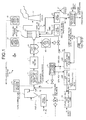
- FIG. 1 is a schematic diagram of an air pollution control system according to a first embodiment.
- an air pollution control system 10 includes: the denitration apparatus 13 that reduces nitrogen oxide in flue gas 12 discharged from the coal combustion boiler 11, and that sprays hydrogen chloride 23 into the gas to oxidize mercury; the air heater 14 that recovers heat in gas from which the nitrogen oxide has been reduced; the dust collector 15 that reduces dust in gas from which the heat has been collected; the desulfurization apparatus 16 that reduces sulfur oxide in gas from which the dust has been reduced; the stack 17 from which desulfurized gas is discharged to the outside; the hydrogen chloride vaporizer 21 that evaporates concentrated hydrochloric acid (35% HCl) to produce hydrogen chloride 23; and a hydrochloric acid neutralization tank 30 where dilute hydrochloric acid (22% HCl) discharged from the hydrogen chloride vaporizer 21 is neutralized with an alkali agent 31.
- neutralized chloride (chloride is, for example, calcium chloride when calcium carbonate is used) is supplied to a fuel feeder 33 and mixed with coal as a fuel 70, and then is burned as a fuel F in the boiler 11. In this way, hydrogen chloride is produced in the flue gas, and together with hydrogen chloride sprayed from the hydrogen chloride vaporizer 21, the mercury is reduced.
- Fig. 1 indicated by reference numerals 41 and 42 are mercury monitors, 43 is a redox potential measurement controller (an oxidation-reduction potential (ORP) controller), and 44 is air.
- ORP oxidation-reduction potential
- lime (powder or slurry) 61 is fed from a lime feeder 60, sulfur oxide in the flue gas is desulfurized, and resulting gypsum slurry 45 is discharged to the outside. Then, gypsum 47 is separated by solid-liquid separation means, such as a belt filter 46.
- Concentrated hydrochloric acid (35% hydrochloric acid) as a feedstock is carried in by a carry-in tank truck 23A from the outside, temporarily stored in a 35% hydrochloric acid tank 22A, and supplied to the hydrogen chloride vaporizer 21, where the hydrogen chloride 23 is evaporated.
- Collected dilute hydrochloric acid, obtained by evaporating the hydrogen chloride 23 and collecting it, has a concentration of about 22%, and is stored in a 22% hydrochloric acid tank 22B.
- the dilute hydrochloric acid is supplied to the hydrochloric acid neutralization tank 30, and neutralized with an alkali agent. As a result, chloride 32 is obtained.
- the concentrated hydrochloric acid (35% hydrochloric acid) to be supplied to the hydrogen chloride vaporizer 21 may be supplied to the hydrochloric acid neutralization tank 30 alone or in combination.
- the alkali agent is not specifically limited.
- Use of lime (calcium carbonate) used in the desulfurization apparatus eliminates the need to buy an alkali agent separately.
- Other alkali agents such as sodium hydroxide and other known alkali agents may be used.
- calcium chloride (aqueous solution) is fed to the fuel feeder 33 through a feed pipe 33c, as shown in Fig. 6 .
- a feeder 33b the calcium chloride is mixed with the fuel (coal) 70 supplied from a hopper 33a, fed to the boiler 11 as the fuel (containing calcium chloride) F, and mixed and burned.
- the chloride 32 in the fuel is burned.
- hydrogen chloride is produced.
- the collected dilute hydrochloric acid (22% HCl), discharged as a waste product, is neutralized in the hydrochloric acid neutralization tank 30. Further, the neutralized chloride 32 is supplied to the boiler 11 and burned to produce hydrogen chloride. Then, together with hydrogen chloride sprayed separately, it is possible to securely reduce mercury in flue gas.
- the conversion rate of converting chlorine compounds to hydrogen chloride during the combustion in the boiler is in a range of about 40% to 60% (about 50%) in general, though it varies depending on the conditions of the combustion in the boiler.
- the ratio of the chloride to be supplied relative to coal be equal to or less than 2000 mg/Kg regarding corrosion of the facilities such as the boiler 11.
- the chlorine concentration in the flue gas between the boiler 11 and the denitration apparatus 13 be equal to or less than 1000 ppm.
- a hydrogen chloride monitor 71 for measuring a concentration of hydrogen chloride is provided between the boiler 11 and the denitration apparatus 13, so that the chloride 32 is supplied under feedback control.
- PRB powder river basin
- bituminous coal when coal is used as the fuel 70 supplied to the boiler 11, powder river basin (PRB) coal may be used, as well as bituminous coal.
- PRB coal is inexpensive and abundantly available in the United States. Compared with bituminous coal, PRB has a lower chlorine concentration, i.e., about one-tenth the chlorine concentration of bituminous coal. When using such coal with low chlorine content, hydrogen chloride is produced less.
- the consumption of concentrated hydrochloric acid is more than that when bituminous coal is used as generally.
- the collected dilute hydrochloric acid (22% HCl), obtained by producing hydrogen chloride from the concentrated hydrochloric acid (35% HCl), is neutralized to be the chloride 32.
- the chloride 32 is burned in the boiler 11 and supplemented as hydrogen chloride. In this way, the dilute hydrochloric acid can be reutilized, and the usage of the concentrated hydrochloric acid can be significantly reduced.
- dilute hydrochloric acid discharged as a by-product resulting from its air pollution control is not disposed to the outside, but reutilized to produce hydrogen chloride in a boiler. Then, together with hydrogen chloride sprayed, mercury in flue gas is oxidized and reduced. As such, by reutilizing the dilute hydrochloric acid, the recycling efficiency can be significantly improved.
- the amount of chlorine in coal significantly varies depending on the type of the coal used as a fuel for combustion in the boiler. Accordingly, the amount of hydrogen chloride to be supplied varies depending on the coal type. Even when the consumption of hydrochloric acid varies depending on the coal type, the production amount of hydrogen chloride can be adjusted by reutilizing the collected dilute hydrochloric acid.
- dilute hydrochloric acid of about 29 tons is produced per day, which counts for 80% of the concentrated hydrochloric acid.
- discharge means such as a tank truck. Accordingly, no disposal cost is required.
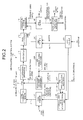
- An air pollution control system 10A shown in Fig. 2 employs, as a coal combustion boiler, the boiler of the air pollution control system 10 shown in Fig. 1 .
- Air pollution control systems 10B and 10C shown in Figs. 3 and 4 are modification examples of the air pollution control system 10A.
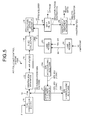
- An air pollution control system 100A shown in Fig. 5 is a comparative example, depicted as a schematic of the related-art air pollution control system 100 shown in Fig. 7 . The configuration of the air pollution control systems are the same as that shown in Fig. 1 , and therefore overlapped descriptions are omitted.
- indicated by a reference numeral 63 is limestone
- 64 is a lime feeder
- 65 lime (calcium carbonate).
- the usage of concentrated hydrochloric acid is less, i.e., about 1.3 tons per hour. Further, no disposal cost is required.
- a portion 48B of the desulfurization wastewater 48, discharged from the desulfurization apparatus 16, is supplied to the hydrochloric acid neutralization tank 30. Then, by diluting the aqueous chloride solution and combustion it in the boiler, it is possible to significantly reduce the amount of treated wastewater to be discharged to the outside.
- calcium chloride produced by a lime gypsum method is present in an aqueous solution (about 20000 ppm).
- the chloride concentration can be increased. This makes it possible to reduce the amount of concentrated hydrochloric acid to be supplied to 1.0 tons per hour, which is about 20% reduction.
- the diluted amount is set so as not to affect the boiler operation, and about 55% to 60% may be used as dilution water.
- a treated wastewater 51B may be supplied to the hydrochloric acid neutralization tank 30 as shown in the air pollution control system 10C of Fig. 4 .
- the cost for buying concentrated hydrochloric acid is 790 million yen per year, and the cost for treating dilute hydrochloric acid is 410 million yen per year.
- the cost for buying concentrated hydrochloric acid is 490 million yen per year relative to the conventional facility. This enables a reduction of about 300 million yen per year in the cost for buying concentrated hydrochloric acid, relative to the conventional facility. Further, no cost is required for treating dilute hydrochloric acid. In total, a reduction of 710 million yen per year is achieved relative to the conventional facility.
- the cost for buying concentrated hydrochloric acid is 350 million yen per year. This enables a reduction of about 440 million yen per year in the cost for buying concentrated hydrochloric acid, relative to the conventional facility. Further, no cost is required for treating dilute hydrochloric acid. In total, a reduction of 850 million yen per year is achieved relative to the conventional facility.
- the present invention is not limited to this.
- a fuel such as refuse-derived fuel (RDF) and industrial waste etc. so as to flue gas containing mercury
- concentrated hydrochloric acid may be vaporized to spray hydrogen chloride in an flue gas flue.
- dilute hydrochloric acid which is residue resulting from production of the hydrogen chloride, and by combustion chloride and the fuel in the boiler, hydrogen chloride is produced. Then, together with hydrogen chloride sprayed, the mercury in flue gas may be securely reduced.
- concentrated hydrochloric acid may be vaporized to produce hydrogen chloride. Further, by neutralizing collected dilute hydrochloric acid and combustion the resultant chloride in the industrial boilers, hydrogen chloride is produced separately, and the production amount of the first hydrogen chloride to be sprayed can be supplemented. This realizes complete recycling within the industrial boiler facilities, thereby significantly improves the recycling efficiency compared with facilities that discharge hydrochloric acid and reutilize it.
- a hydrogen chloride feeder As described, in a hydrogen chloride feeder according to the present invention, dilute hydrochloric acid discharged as a waste product is neutralized to be chloride, and burned in a boiler. In this way, the hydrogen chloride feeder can reutilize the hydrochloric acid as hydrogen chloride, and therefore is suitably used in treatment of hydrochloric acid for treating flue gas in a power station.
Landscapes
- Engineering & Computer Science (AREA)
- Chemical & Material Sciences (AREA)
- Environmental & Geological Engineering (AREA)
- General Chemical & Material Sciences (AREA)
- Chemical Kinetics & Catalysis (AREA)
- Biomedical Technology (AREA)
- Analytical Chemistry (AREA)
- Health & Medical Sciences (AREA)
- Oil, Petroleum & Natural Gas (AREA)
- Mechanical Engineering (AREA)
- General Engineering & Computer Science (AREA)
- Treating Waste Gases (AREA)
- Chimneys And Flues (AREA)
- Separation Of Suspended Particles By Flocculating Agents (AREA)
- Exhaust Gas Treatment By Means Of Catalyst (AREA)
Abstract
Description
- The present invention relates to an air pollution control system that reduces mercury in flue gas discharged from a boiler, and to a method for removing mercury in flue gas.
- Conventionally, various systems for removing mercury in flue gas have been considered because, for example, coal combustion boilers serving as combustion apparatuses in power stations and other facilities discharge flue gas containing highly toxic mercury.
- A coal combustion boiler generally includes a wet desulfurization apparatus for removing sulfur content in flue gas. In flue gas treatment facilities including such a boiler provided with a desulfurization apparatus that serves an air pollution control apparatus, as chlorine (Cl) content increases in flue gas, the ratio of water-soluble divalent metallic mercury increases. This facilitates collection of the mercury with the desulfurization apparatus, as is well known.
- In recent years, various proposals have been made on denitration apparatuses that reduce NOx, and on methods and apparatuses for treating the metallic mercury in combination with a wet desulfurization apparatus that uses an alkali absorbing solution as SOx absorbent.
- As treatment of metallic mercury in flue gas, removal methods using an absorbent such as activated carbon or a selenium filter have been known. These methods, however, require special means for absorption removal, and are not suitable for treatment of a large volume of flue gas, such as flue gas in power stations.
- As a method for treating metallic mercury in a large volume of flue gas, methods have been proposed that include: gas-atomizing a chlorinating agent in a flue at an upstream process in a high-temperature denitration apparatus, oxidizing (chlorinating) the mercury on a denitration catalyst to be aqueous hydrogen chloride, and then absorbing it in a downstream wet desulfurization apparatus (for example, see Patent Documents 1 and 2). Apparatuses and techniques for spraying gas in a flue have been commercialized as NH3 spray devices of denitration apparatuses, and the same means can be used for gas atomization of a chlorinating agent.
-
Fig. 7 depicts an example of a conventional mercury removal system.
As shown inFig. 7 , a related-art airpollution control system 100 includes: adenitration apparatus 13 that reduces nitrogen oxide influe gas 12 discharged from acoal combustion boiler 11 that supplies coal as a fuel F, and that sprayshydrogen chloride 23 into the gas to oxidize mercury; anair heater 14 that recovers heat in gas from which the nitrogen oxide has been reduced; adust collector 15 that reduces dust in gas from which the heat has been collected; adesulfurization apparatus 16 that reduces sulfur oxide in gas from which the dust has been reduced; astack 17 from which desulfurized gas is discharged to the outside; and ahydrogen chloride vaporizer 21 that produces thehydrogen chloride 23.
InFig. 7 , indicated byreference numerals - A proposal has been made of supplying, instead of spraying hydrogen chloride into flue gas, chlorine compounds during combustion in the boiler so as to produce hydrogen chloride during the combustion (Patent Document 3).
-
- Patent Document 1: Japanese Patent Application Laid-open No.
10-230137 - Patent Document 2: Japanese Patent No.
3935547 - Patent Document 3: Japanese Patent No.
3698916 - When employing the mercury removal systems that spray hydrogen chloride or the like as proposed in
Patent Documents 1 and 2, 35% hydrochloric acid is evaporated in the hydrogen chloride vaporizer. Accordingly, a large amount of concentrated hydrochloric acid is required, and the resulting by-product, i.e., dilute hydrochloric acid, is discharged by an amount equivalent to about 80% of the concentrated hydrochloric acid (35% hydrochloric acid). This poses a problem that the dilute hydrochloric acid results in a waste product for the power station. - The chlorine concentration varies depending on the type of coal used in the power station (i.e., coal type). Even when a coal type with high chloride concentration is used, a large amount of 35% concentrated hydrochloric acid is necessary, and dilute hydrochloric acid is discharged by an amount equivalent to 80% of the 35% concentrated hydrochloric acid.
Thus, to establish recycling plants as ancillary facilities to treat the dilute hydrochloric acid as a waste product, a set of plants needs to be established. This increases costs for establishing and maintaining the plants. - It is also considered to establish recycling plants within power generating facilities. This requires, however, substantial addition in treatment processes because non volatile materials are circulated and concentrated in the treatment of the dilute hydrochloric acid.
- In the proposal of Patent Document 3, hydrogen chloride is produced by combustion in the boiler. The efficiency of converting chlorine compounds to hydrogen chloride in the boiler varies depending on the combustion in the boiler, and therefore is not constant. In addition, the mercury concentration in flue gas is not constant all the time. This poses a problem that hydrogen chloride cannot be supplied by a constant amount so that mercury is securely reduced as mercury chloride.
- Thus, there is a demand to establish an inexpensive mercury removal system that disposes no dilute hydrochloric acid discharged as a by-product, and that can stably reduce mercury.
- The present invention is made in view of the foregoing, and has an object to provide an air pollution control system and a method for removing mercury in flue gas that reduce operating costs.
- To solve the above problem, according to the first invention of the present invention, an air pollution control system comprises: a denitration apparatus that reduces nitrogen oxide in flue gas discharged from an industrial boiler, and that sprays hydrogen chloride into the flue gas to oxidize mercury; a desulfurization apparatus that reduces sulfur oxide in flue gas thus denitrated; a stack from which gas thus desulfurized is discharged outside; a hydrogen chloride vaporizer that produces hydrogen chloride with a supply of concentrated hydrochloric acid; and a hydrochloric acid neutralization tank where at least one of dilute hydrochloric acid discharged from the hydrogen chloride vaporizer and the concentrated hydrochloric acid is neutralized with an alkali agent. Chloride resulting from such neutralization is supplied to a fuel, and then burned in the industrial boiler to produce hydrogen chloride in flue gas, and, together with hydrogen chloride sprayed, the mercury is reduced.
- According to the second invention, an air pollution control system comprises: a spray device that sprays hydrogen chloride into flue gas discharged from a coal combustion boiler; a denitration apparatus that reduces nitrogen oxide in flue gas into which the hydrogen chloride has been sprayed, and that oxides mercury; an air heater that recovers heat in gas from which the nitrogen oxide has been reduced; a dust collector that reduces dust in gas from which the heat has been collected; a desulfurization apparatus that reduces sulfur oxide in gas from which the dust has been reduced; a stack from which gas thus desulfurized is discharged outside; a hydrogen chloride vaporizer that produces hydrogen chloride with a supply of concentrated hydrochloric acid; and a hydrochloric acid neutralization tank where at least one of dilute hydrochloric acid discharged from the hydrogen chloride vaporizer and the concentrated hydrochloric acid is neutralized with an alkali agent. Neutralized chloride is supplied to a coal feeder, mixed with coal, and then burned in the coal combustion boiler, so as to produce hydrogen chloride in flue gas, and, together with hydrogen chloride sprayed, the mercury is reduced.
- According to the third invention, in the air pollution control system according to the first invention or the second invention, desulfurization wastewater discharged from the desulfurization apparatus, or treated wastewater obtained by removing heavy metals from the desulfurization wastewater is supplied to the hydrochloric acid neutralization tank.
- According to the forth invention, in the air pollution control system according to any one of the first invention to the third invention, the air pollution control system further comprises a hydrogen chloride monitor that measures a concentration of hydrogen chloride between the boiler and the denitration apparatus. The chloride is supplied under feedback control.
- According to the fifth invention, in the air pollution control system according to any one of the first invention to the forth invention, flue gas between the boiler and the denitration apparatus has a chlorine concentration being equal to or less than 1000 ppm.
- According to the sixth invention, a method for removing mercury in flue gas comprises: removing nitrogen oxide in flue gas discharged from an industrial boiler, and spraying hydrogen chloride into the flue gas, so as to oxidize mercury; neutralizing with an alkali agent dilute hydrochloric acid discharged after the hydrogen chloride is produced; and supplying neutralized chloride to a fuel, and then combustion the chlorine in the boiler to produce hydrogen chloride in flue gas, and removing the mercury together with hydrogen chloride sprayed.
- According to the present invention, dilute hydrochloric acid discharged as a waste product is neutralized, supplied to a boiler as chloride, and burned to produce hydrogen chloride. Then, together with hydrogen chloride sprayed separately, it is possible to securely reduce mercury in flue gas.
- Further, desulfurization wastewater discharged from a desulfurization apparatus is neutralized, and used as an aqueous chloride solution to be burned in the boiler. In this way, the amount of wastewater to be discharged outside can be significantly reduced.
-
- [
Fig. 1] Fig. 1 is a diagram of an air pollution control system according to a first embodiment. - [
Fig. 2] Fig. 2 is a schematic diagram of an air pollution control system as an example of application of the first embodiment. - [
Fig. 3] Fig. 3 is a schematic diagram of an air pollution control system as an example of application of a second embodiment. - [
Fig. 4] Fig. 4 is a schematic diagram of an air pollution control system as another example of application of the second embodiment. - [
Fig. 5] Fig. 5 is a schematic diagram of an air pollution control system as a conventional facility. - [
Fig. 6] Fig. 6 is a schematic of a fuel feeder. - [
Fig. 7] Fig. 7 is a diagram of a related-art air pollution control system. -
- 11
- coal combustion boiler
- 12
- flue gas
- 13
- denitration apparatus
- 14
- air heater
- 15
- dust collector
- 16
- desulfurization apparatus
- 17
- stack
- 21
- hydrogen chloride vaporizer
- 23
- hydrogen chloride
- 30
- hydrochloric acid neutralization tank
- 32
- neutralized chloride
- 64
- lime feeder
- Exemplary embodiments of the present invention will be described in detail with reference to the accompanying drawings. The present invention is not limited by the embodiments. Constituting elements in the embodiments include elements that can be easily achieved by a person skilled in the art, or elements being substantially the same as those elements.
-
Fig. 1 is a schematic diagram of an air pollution control system according to a first embodiment.
As shown inFig. 1 , an airpollution control system 10 according to the present embodiment includes: thedenitration apparatus 13 that reduces nitrogen oxide influe gas 12 discharged from thecoal combustion boiler 11, and thatsprays hydrogen chloride 23 into the gas to oxidize mercury; theair heater 14 that recovers heat in gas from which the nitrogen oxide has been reduced; thedust collector 15 that reduces dust in gas from which the heat has been collected; thedesulfurization apparatus 16 that reduces sulfur oxide in gas from which the dust has been reduced; thestack 17 from which desulfurized gas is discharged to the outside; thehydrogen chloride vaporizer 21 that evaporates concentrated hydrochloric acid (35% HCl) to producehydrogen chloride 23; and a hydrochloricacid neutralization tank 30 where dilute hydrochloric acid (22% HCl) discharged from thehydrogen chloride vaporizer 21 is neutralized with analkali agent 31. In the airpollution control system 10, neutralized chloride (chloride is, for example, calcium chloride when calcium carbonate is used) is supplied to afuel feeder 33 and mixed with coal as afuel 70, and then is burned as a fuel F in theboiler 11. In this way, hydrogen chloride is produced in the flue gas, and together with hydrogen chloride sprayed from thehydrogen chloride vaporizer 21, the mercury is reduced.
InFig. 1 , indicated byreference numerals - In the
desulfurization apparatus 16, lime (powder or slurry) 61 is fed from alime feeder 60, sulfur oxide in the flue gas is desulfurized, and resultinggypsum slurry 45 is discharged to the outside. Then,gypsum 47 is separated by solid-liquid separation means, such as abelt filter 46. The separate liquid, i.e.,desulfurization wastewater 48, containsheavy metal 52, which is coagulated and deposited by a coagulant in awastewater treatment apparatus 50, and discharged to the outside as treatedwastewater 51. - Concentrated hydrochloric acid (35% hydrochloric acid) as a feedstock is carried in by a carry-in
tank truck 23A from the outside, temporarily stored in a 35%hydrochloric acid tank 22A, and supplied to thehydrogen chloride vaporizer 21, where thehydrogen chloride 23 is evaporated.
Collected dilute hydrochloric acid, obtained by evaporating thehydrogen chloride 23 and collecting it, has a concentration of about 22%, and is stored in a 22%hydrochloric acid tank 22B.
The dilute hydrochloric acid is supplied to the hydrochloricacid neutralization tank 30, and neutralized with an alkali agent. As a result,chloride 32 is obtained. - In the present invention, instead of the collected dilute hydrochloric acid, the concentrated hydrochloric acid (35% hydrochloric acid) to be supplied to the
hydrogen chloride vaporizer 21 may be supplied to the hydrochloricacid neutralization tank 30 alone or in combination.
In particular, it is preferable to supply the concentrated hydrochloric acid (35% hydrochloric acid) when, for example, thehydrogen chloride vaporizer 21 is stopped, because hydrogen chloride can be securely produced in the flue gas discharged from theboiler 11. - In the present invention, the alkali agent is not specifically limited. Use of lime (calcium carbonate) used in the desulfurization apparatus eliminates the need to buy an alkali agent separately. Other alkali agents such as sodium hydroxide and other known alkali agents may be used.
- As the resultant chloride, calcium chloride (aqueous solution) is fed to the
fuel feeder 33 through afeed pipe 33c, as shown inFig. 6 . Then, in afeeder 33b, the calcium chloride is mixed with the fuel (coal) 70 supplied from ahopper 33a, fed to theboiler 11 as the fuel (containing calcium chloride) F, and mixed and burned.
During the combustion, thechloride 32 in the fuel is burned. As a result, hydrogen chloride is produced. - As such, according to the present invention, the collected dilute hydrochloric acid (22% HCl), discharged as a waste product, is neutralized in the hydrochloric
acid neutralization tank 30. Further, the neutralizedchloride 32 is supplied to theboiler 11 and burned to produce hydrogen chloride. Then, together with hydrogen chloride sprayed separately, it is possible to securely reduce mercury in flue gas. - This eliminates the process for transporting outside the collected dilute hydrochloric acid obtained by producing hydrogen chloride and collecting it, which has been required in related art.
The collected dilute hydrochloric acid is neutralized and reutilized as chlorine compounds. Further, by combustion the chlorine compounds in the boiler, second hydrogen chloride is produced in the boiler. Then, together with first hydrogen chloride derived from the concentrated hydrochloric acid and originally fed from thehydrogen chloride vaporizer 21, it is possible to reduce mercury in flue gas. Thus, the amount of the first hydrogen chloride produced in thehydrogen chloride vaporizer 21 can be reduced by the amount of the second hydrogen chloride produced in theboiler 11. This significantly reduces the amount of the concentrated hydrochloric acid (35% HCl) bought and transported from the outside for mercury removal. - The conversion rate of converting chlorine compounds to hydrogen chloride during the combustion in the boiler is in a range of about 40% to 60% (about 50%) in general, though it varies depending on the conditions of the combustion in the boiler.
As the amount ofchloride 32 to be supplied to thefuel 70, it is preferable that the ratio of the chloride to be supplied relative to coal be equal to or less than 2000 mg/Kg regarding corrosion of the facilities such as theboiler 11. - For efficiently removing mercury in flue gas and considering chlorine concentration in wastewater in the system, it is preferable that the chlorine concentration in the flue gas between the
boiler 11 and thedenitration apparatus 13 be equal to or less than 1000 ppm.
To this end, a hydrogen chloride monitor 71 for measuring a concentration of hydrogen chloride is provided between theboiler 11 and thedenitration apparatus 13, so that thechloride 32 is supplied under feedback control. - This makes it possible to efficiently reduce mercury in flue gas. Further, by making the concentration of hydrogen chloride to be sprayed into the flue gas be equal to or less than 1000 ppm, it is possible to make the chlorine concentration in the treated
wastewater 51 to be discharged to the outside from thedesulfurization apparatus 16 be equal to or less than a predetermined value of an environmental discharge standard. - In the present invention, when coal is used as the
fuel 70 supplied to theboiler 11, powder river basin (PRB) coal may be used, as well as bituminous coal.
PRB coal is inexpensive and abundantly available in the United States. Compared with bituminous coal, PRB has a lower chlorine concentration, i.e., about one-tenth the chlorine concentration of bituminous coal.
When using such coal with low chlorine content, hydrogen chloride is produced less. When not reutilizing the collected hydrochloric acid as in the present invention, the consumption of concentrated hydrochloric acid is more than that when bituminous coal is used as generally. In the present invention, the collected dilute hydrochloric acid (22% HCl), obtained by producing hydrogen chloride from the concentrated hydrochloric acid (35% HCl), is neutralized to be thechloride 32. Then, thechloride 32 is burned in theboiler 11 and supplemented as hydrogen chloride. In this way, the dilute hydrochloric acid can be reutilized, and the usage of the concentrated hydrochloric acid can be significantly reduced. - According to the present invention, for example, in a power station including an air pollution control facility, dilute hydrochloric acid discharged as a by-product resulting from its air pollution control is not disposed to the outside, but reutilized to produce hydrogen chloride in a boiler. Then, together with hydrogen chloride sprayed, mercury in flue gas is oxidized and reduced. As such, by reutilizing the dilute hydrochloric acid, the recycling efficiency can be significantly improved.
- The amount of chlorine in coal significantly varies depending on the type of the coal used as a fuel for combustion in the boiler. Accordingly, the amount of hydrogen chloride to be supplied varies depending on the coal type. Even when the consumption of hydrochloric acid varies depending on the coal type, the production amount of hydrogen chloride can be adjusted by reutilizing the collected dilute hydrochloric acid.
- For example, when a small power plant utilizes concentrated hydrochloric acid of 35 tons per day, dilute hydrochloric acid of about 29 tons is produced per day, which counts for 80% of the concentrated hydrochloric acid. In this case, by neutralizing the dilute hydrochloric acid in a hydrochloric acid neutralization tank and combustion it in a boiler as described, there is no need to transport the dilute hydrochloric acid to the outside with discharge means such as a tank truck. Accordingly, no disposal cost is required.
- As a result, costs are required only for buying concentrated hydrochloric acid. Thus, it is possible to provide a mercury removal system requiring low operating costs, for mercury removal from flue gas. In addition, the amount of concentrated hydrochloric acid to be carried in is also reduced because the collected dilute hydrochloric acid is reutilized to produce hydrogen chloride from chloride and supplement it. In this way, cost reduction is significantly achieved compared with conventional systems.
- Further, no cost is required for treating the collected dilute hydrochloric acid, which has been required for every treatment of mercury. This also contributes to the significant reduction in running costs.
- The following describes a power generating facility that generates power of 600 megawatts, for example, to which the present invention is applied for removing mercury in flue gas. Assume that a boiler discharges flue gas at 2 million m3 per hour.
An airpollution control system 10A shown inFig. 2 employs, as a coal combustion boiler, the boiler of the airpollution control system 10 shown inFig. 1 . Airpollution control systems Figs. 3 and4 are modification examples of the airpollution control system 10A. An airpollution control system 100A shown inFig. 5 is a comparative example, depicted as a schematic of the related-art airpollution control system 100 shown inFig. 7 . The configuration of the air pollution control systems are the same as that shown inFig. 1 , and therefore overlapped descriptions are omitted.
InFigs. 2 to 4 , indicated by areference numeral 63 is limestone, 64 is a lime feeder, and 65 is lime (calcium carbonate). - In the air
pollution control system 100A shown inFig. 5 as a conventional facility, when the amount of flue gas is 2 million m3 per hour, no hydrochloric acid is reutilized. When collected dilute hydrochloric acid (22% HCl) is all transported to the outside, the usage of concentrated hydrochloric acid (35% HCl) is 1.9 tons per hour, and the discharge amount of dilute hydrochloric acid (22% HCl) is 1.5 tons per hour. As a result, costs are required for buying the concentrated hydrochloric acid and treating the dilute hydrochloric acid. - In contrast, in the air
pollution control system 10A shown inFig. 2 , to which the present invention is applied, the usage of concentrated hydrochloric acid is less, i.e., about 1.3 tons per hour. Further, no disposal cost is required. - In the air
pollution control system 10B shown inFig. 3 , aportion 48B of thedesulfurization wastewater 48, discharged from thedesulfurization apparatus 16, is supplied to the hydrochloricacid neutralization tank 30. Then, by diluting the aqueous chloride solution and combustion it in the boiler, it is possible to significantly reduce the amount of treated wastewater to be discharged to the outside. - In the
desulfurization wastewater 48, calcium chloride produced by a lime gypsum method is present in an aqueous solution (about 20000 ppm). By supplying it to the hydrochloricacid neutralization tank 30, the chloride concentration can be increased. This makes it possible to reduce the amount of concentrated hydrochloric acid to be supplied to 1.0 tons per hour, which is about 20% reduction.
The diluted amount is set so as not to affect the boiler operation, and about 55% to 60% may be used as dilution water. - Instead of the
desulfurization wastewater 48, a treatedwastewater 51B may be supplied to the hydrochloricacid neutralization tank 30 as shown in the airpollution control system 10C ofFig. 4 . - The following describes a comparison between a power generating facility of 600 megawatts that buys concentrated hydrochloric acid according to the present invention (35% HCl) and reutilizes it, and a power generating facility of 600 megawatts that buys conventional concentrated hydrochloric acid and disposes dilute hydrochloric acid (22% HCl) to the outside. Assume that these facilities are operated for 10 years.
- In the air
pollution control system 100A shown inFig. 5 as a conventional facility, the cost for buying concentrated hydrochloric acid is 790 million yen per year, and the cost for treating dilute hydrochloric acid is 410 million yen per year.
In contrast, in the airpollution control system 10A shown inFig. 2 , the cost for buying concentrated hydrochloric acid is 490 million yen per year relative to the conventional facility. This enables a reduction of about 300 million yen per year in the cost for buying concentrated hydrochloric acid, relative to the conventional facility. Further, no cost is required for treating dilute hydrochloric acid. In total, a reduction of 710 million yen per year is achieved relative to the conventional facility. - In the air
pollution control system 10B shown inFig. 3 , the cost for buying concentrated hydrochloric acid is 350 million yen per year. This enables a reduction of about 440 million yen per year in the cost for buying concentrated hydrochloric acid, relative to the conventional facility. Further, no cost is required for treating dilute hydrochloric acid. In total, a reduction of 850 million yen per year is achieved relative to the conventional facility. - Because this estimation is based on ten-year operation, a further reduction is achieved for a longer operation period, e.g., 15 years or 20 years.
- Further, when dilute hydrochloric acid is disposed to the outside from the conventional facility, an acid-proof tank is required as a storage tank for storing therein the dilute hydrochloric acid within the power generating facility. This significantly increases construction costs of such a conventional facility.
- In the present invention, although the foregoing describes a coal combustion boiler using coal as a fuel, the present invention is not limited to this. For example, in an industrial boiler facility that burns a fuel such as refuse-derived fuel (RDF) and industrial waste etc. so as to flue gas containing mercury, concentrated hydrochloric acid may be vaporized to spray hydrogen chloride in an flue gas flue. Further, by neutralizing dilute hydrochloric acid, which is residue resulting from production of the hydrogen chloride, and by combustion chloride and the fuel in the boiler, hydrogen chloride is produced. Then, together with hydrogen chloride sprayed, the mercury in flue gas may be securely reduced.
- In small and medium scale industrial boilers also, concentrated hydrochloric acid may be vaporized to produce hydrogen chloride. Further, by neutralizing collected dilute hydrochloric acid and combustion the resultant chloride in the industrial boilers, hydrogen chloride is produced separately, and the production amount of the first hydrogen chloride to be sprayed can be supplemented. This realizes complete recycling within the industrial boiler facilities, thereby significantly improves the recycling efficiency compared with facilities that discharge hydrochloric acid and reutilize it.
- As described, in a hydrogen chloride feeder according to the present invention, dilute hydrochloric acid discharged as a waste product is neutralized to be chloride, and burned in a boiler. In this way, the hydrogen chloride feeder can reutilize the hydrochloric acid as hydrogen chloride, and therefore is suitably used in treatment of hydrochloric acid for treating flue gas in a power station.
Claims (6)
- An air pollution control system comprising:a denitration apparatus that reduces nitrogen oxide in flue gas discharged from an industrial boiler, and that injects hydrogen chloride into the flue gas to oxidize mercury;a desulfurization apparatus that reduces sulfur oxide in flue gas thus denitrated;a stack from which gas thus desulfurized is discharged outside;a hydrogen chloride vaporizer that produces hydrogen chloride with a supply of concentrated hydrochloric acid; anda hydrochloric acid neutralization tank where at least one of dilute hydrochloric acid discharged from the hydrogen chloride vaporizer and the concentrated hydrochloric acid is neutralized with an alkali agent, whereinchloride resulting from such neutralization is supplied to a fuel, and then burned in the industrial boiler to produce hydrogen chloride in flue gas, and, together with hydrogen chloride sprayed, the mercury is reduced.
- An air pollution control system comprising:a spray device that sprays hydrogen chloride into flue gas discharged from a coal combustion boiler;a denitration apparatus that reduces nitrogen oxide in flue gas into which the hydrogen chloride has been sprayed, and that oxides mercury;an air heater that recovers heat in gas from which the nitrogen oxidizes has been reduced;a dust collector that reduces dust in gas from which the heat has been collected;a desulfurization apparatus that reduces sulfur oxide in gas from which the dust has been reduced;a stack from which gas thus desulfurized is discharged outside;a hydrogen chloride vaporizer that produces hydrogen chloride with a supply of concentrated hydrochloric acid; anda hydrochloric acid neutralization tank where at least one of dilute hydrochloric acid discharged from the hydrogen chloride vaporizer and the concentrated hydrochloric acid is neutralized with an alkali agent, whereinneutralized chloride is supplied to a coal feeder, mixed with coal, and then burned in the coal combustion boiler, so as to produce hydrogen chloride in flue gas, and, together with hydrogen chloride sprayed, the mercury is reduced.
- The air pollution control system according to claim 1 or 2, wherein desulfurization wastewater discharged from the desulfurization apparatus, or treated wastewater obtained by removing heavy metals from the desulfurization wastewater is supplied to the hydrochloric acid neutralization tank.
- The air pollution control system according to any one of claims 1 to 3, further comprising a hydrogen chloride monitor that measures a concentration of hydrogen chloride between the boiler and the denitration apparatus, wherein
the chloride is supplied under feedback control. - The air pollution control system according to any one of claims 1 to 4, wherein flue gas between the boiler and the denitration apparatus has a chlorine concentration being equal to or less than 1000 ppm.
- A method for removing mercury in flue gas, the method comprising:removing nitrogen oxide in flue gas discharged from an industrial boiler, and spraying hydrogen chloride into the flue gas, so as to oxidize mercury;neutralizing with an alkali agent dilute hydrochloric acid discharged after the hydrogen chloride is produced; andsupplying neutralized chloride to a fuel, and then burning the chlorine in the boiler to produce hydrogen chloride in flue gas, and removing the mercury together with hydrogen chloride sprayed.
Applications Claiming Priority (2)
| Application Number | Priority Date | Filing Date | Title |
|---|---|---|---|
| JP2008116350A JP5484689B2 (en) | 2008-04-25 | 2008-04-25 | Exhaust gas treatment system and method for removing mercury in exhaust gas |
| PCT/JP2008/071052 WO2009130815A1 (en) | 2008-04-25 | 2008-11-19 | System for treating discharge gas and method of removing mercury from discharge gas |
Publications (2)
| Publication Number | Publication Date |
|---|---|
| EP2269714A1 true EP2269714A1 (en) | 2011-01-05 |
| EP2269714A4 EP2269714A4 (en) | 2011-11-23 |
Family
ID=41215206
Family Applications (1)
| Application Number | Title | Priority Date | Filing Date |
|---|---|---|---|
| EP08874032A Withdrawn EP2269714A4 (en) | 2008-04-25 | 2008-11-19 | System for treating discharge gas and method of removing mercury from discharge gas |
Country Status (10)
| Country | Link |
|---|---|
| US (1) | US7704472B2 (en) |
| EP (1) | EP2269714A4 (en) |
| JP (1) | JP5484689B2 (en) |
| KR (1) | KR101229680B1 (en) |
| CN (1) | CN102015070B (en) |
| BR (1) | BRPI0822538A2 (en) |
| CA (1) | CA2719520C (en) |
| CL (1) | CL2009000204A1 (en) |
| SA (1) | SA109300066B1 (en) |
| WO (1) | WO2009130815A1 (en) |
Cited By (1)
| Publication number | Priority date | Publication date | Assignee | Title |
|---|---|---|---|---|
| CN110997111A (en) * | 2017-07-06 | 2020-04-10 | 埃科莱布美国股份有限公司 | Enhanced mercury oxidant injection |
Families Citing this family (23)
| Publication number | Priority date | Publication date | Assignee | Title |
|---|---|---|---|---|
| JP5350996B2 (en) * | 2009-11-25 | 2013-11-27 | バブコック日立株式会社 | Oxygen combustion system exhaust gas treatment equipment |
| PL2540378T3 (en) | 2010-02-25 | 2017-05-31 | Mitsubishi Heavy Industries, Ltd. | Exhaust gas treatment system, and exhaust gas treatment method |
| JP5554162B2 (en) * | 2010-06-30 | 2014-07-23 | 三菱重工業株式会社 | Mercury treatment system in exhaust gas |
| EP2628527B1 (en) | 2010-10-15 | 2019-05-22 | Mitsubishi Hitachi Power Systems, Ltd. | System for processing mercury in exhaust gas |
| CN102500208A (en) * | 2011-11-18 | 2012-06-20 | 山东大学 | Utilization method and device for wet flue gas desulfurization wastewater |
| US20140079615A1 (en) * | 2012-09-14 | 2014-03-20 | Mitsubishi Heavy Industries, Ltd. | Exhaust gas treatment system and a method of treating exhaust gas |
| CN104437031A (en) * | 2014-11-05 | 2015-03-25 | 朱忠良 | Iron smelting flue gas treatment method |
| WO2016132894A1 (en) * | 2015-02-18 | 2016-08-25 | Jfeエンジニアリング株式会社 | Exhaust gas treatment device and exhaust gas treatment method |
| EP3093274A4 (en) * | 2015-03-19 | 2016-11-16 | Mitsubishi Heavy Ind Ltd | Water treatment system and power generation apparatus |
| JP6637682B2 (en) | 2015-06-18 | 2020-01-29 | 三菱日立パワーシステムズ株式会社 | Exhaust gas treatment device for coal-fired boiler and exhaust gas treatment method for coal-fired boiler |
| CN105879622A (en) * | 2016-05-12 | 2016-08-24 | 大唐环境产业集团股份有限公司 | Two-stage denitrification device and method for realizing near-zero discharge |
| JP6703748B2 (en) * | 2016-09-12 | 2020-06-03 | Jfeエンジニアリング株式会社 | Exhaust gas treatment device and exhaust gas treatment method |
| EP3351505A1 (en) * | 2017-01-20 | 2018-07-25 | Covestro Deutschland AG | Method for flexible control of the use of hydrochloric acid from chemical production |
| CN108164074A (en) * | 2018-01-30 | 2018-06-15 | 四川思达能环保科技有限公司 | A kind of metal chloride waste water treatment system and method |
| CN108704455A (en) * | 2018-07-05 | 2018-10-26 | 安徽顺达环保科技股份有限公司 | A kind of flue gas desulfurization denitration dust-removing technique |
| KR102166989B1 (en) * | 2018-10-17 | 2020-10-16 | 한국생산기술연구원 | Phosphorus recovery system in pressurized oxygen combustion ash |
| KR102186251B1 (en) * | 2019-03-29 | 2020-12-03 | 한국동서발전(주) | method for recycling of desulfurization process water |
| CN110841481A (en) * | 2019-12-12 | 2020-02-28 | 北京京诚科林环保科技有限公司 | Sintering flue gas double-heating SCR denitration method and system |
| KR102201771B1 (en) | 2019-12-26 | 2021-01-13 | 대구대학교 산학협력단 | Ammonium chloride Injection Device for Elemental Mercury Oxidation in SCR Reactor and Injection Method using the same |
| KR102404379B1 (en) | 2021-11-29 | 2022-05-31 | 대구대학교 산학협력단 | Device for Elemental Mercury Oxidation and/or Nigrogen Oxide removal using Ammonium chloride of Solid type and Method for Elemental Mercury Oxidation and/or Nigrogen Oxide removal using the same |
| CN114377531A (en) * | 2022-01-19 | 2022-04-22 | 中建中环工程有限公司 | Coal-fired boiler flue gas desulfurization and denitrification synergistic treatment system and treatment method |
| KR20240076237A (en) | 2022-11-23 | 2024-05-30 | 대구대학교 산학협력단 | Functionalized biochar with sulfur for adsorbing gaseous mercury and Manufacturing method thereof |
| CN116293757B (en) * | 2023-04-12 | 2026-03-24 | 西安交通大学 | A chemical looping combustion mercury removal system and method based on oxygen carrier and oxygen-chlorine dual cycle |
Family Cites Families (7)
| Publication number | Priority date | Publication date | Assignee | Title |
|---|---|---|---|---|
| CA2114331C (en) * | 1993-06-10 | 2000-03-28 | Bernard J. Lerner | Removal of mercury and cadmium and their compounds from incinerator flue gases |
| JP3935547B2 (en) | 1997-02-19 | 2007-06-27 | 三菱重工業株式会社 | Exhaust gas treatment method and exhaust gas treatment apparatus |
| US6503470B1 (en) * | 1999-03-31 | 2003-01-07 | The Babcock & Wilcox Company | Use of sulfide-containing liquors for removing mercury from flue gases |
| JP3698916B2 (en) * | 1999-05-19 | 2005-09-21 | バブコック日立株式会社 | Method and apparatus for removing mercury from coal flue gas |
| JP2006263700A (en) * | 2005-02-28 | 2006-10-05 | Mitsubishi Heavy Ind Ltd | Method and system for removing mercury in exhaust gas |
| JP4838579B2 (en) * | 2005-12-21 | 2011-12-14 | 三菱重工業株式会社 | Mercury removal system and mercury removal method |
| CN1923337A (en) * | 2006-08-23 | 2007-03-07 | 浙江大学 | Boiler smoke gas multipollutant ozonization and simultaneous elimination device and method therefor |
-
2008
- 2008-04-25 JP JP2008116350A patent/JP5484689B2/en not_active Expired - Fee Related
- 2008-11-19 BR BRPI0822538A patent/BRPI0822538A2/en not_active IP Right Cessation
- 2008-11-19 CA CA2719520A patent/CA2719520C/en not_active Expired - Fee Related
- 2008-11-19 KR KR1020107021260A patent/KR101229680B1/en not_active Expired - Fee Related
- 2008-11-19 WO PCT/JP2008/071052 patent/WO2009130815A1/en not_active Ceased
- 2008-11-19 EP EP08874032A patent/EP2269714A4/en not_active Withdrawn
- 2008-11-19 CN CN2008801288184A patent/CN102015070B/en not_active Expired - Fee Related
-
2009
- 2009-01-27 SA SA109300066A patent/SA109300066B1/en unknown
- 2009-01-30 CL CL2009000204A patent/CL2009000204A1/en unknown
- 2009-01-30 US US12/362,849 patent/US7704472B2/en not_active Expired - Fee Related
Cited By (1)
| Publication number | Priority date | Publication date | Assignee | Title |
|---|---|---|---|---|
| CN110997111A (en) * | 2017-07-06 | 2020-04-10 | 埃科莱布美国股份有限公司 | Enhanced mercury oxidant injection |
Also Published As
| Publication number | Publication date |
|---|---|
| BRPI0822538A2 (en) | 2019-09-24 |
| US20090269262A1 (en) | 2009-10-29 |
| JP2009262081A (en) | 2009-11-12 |
| CN102015070B (en) | 2013-09-04 |
| JP5484689B2 (en) | 2014-05-07 |
| SA109300066B1 (en) | 2013-07-23 |
| HK1150395A1 (en) | 2011-12-23 |
| KR20100131461A (en) | 2010-12-15 |
| WO2009130815A1 (en) | 2009-10-29 |
| KR101229680B1 (en) | 2013-02-04 |
| CN102015070A (en) | 2011-04-13 |
| EP2269714A4 (en) | 2011-11-23 |
| CA2719520A1 (en) | 2009-10-29 |
| US7704472B2 (en) | 2010-04-27 |
| CL2009000204A1 (en) | 2009-08-07 |
| CA2719520C (en) | 2012-05-01 |
Similar Documents
| Publication | Publication Date | Title |
|---|---|---|
| CA2719520C (en) | Air pollution control system and method for removing mercury in flue gas | |
| US8071060B2 (en) | Flue gas control system of coal combustion boiler and operating method thereof | |
| JP5972983B2 (en) | Exhaust gas treatment system and exhaust gas treatment method | |
| EP1800734A1 (en) | Mercury removal system and mercury removal process | |
| KR20000062190A (en) | Mercury removal in utility wet scrubber using a chelating agent | |
| EP2221101B1 (en) | Method for softening water for use in a scrubber | |
| EP2939728A1 (en) | Exhaust gas processing device and exhaust gas processing method | |
| CN105032137B (en) | A kind of quick lime-ammonia associating flue gas desulfurization and denitrification integrated apparatus | |
| CN100360212C (en) | Treatment method for resource removal of sulfur dioxide waste gas | |
| JP4942559B2 (en) | Exhaust gas purifier and method for capturing harmful trace elements | |
| EP2444144A1 (en) | System for removing mercury and method of removing mercury from mercury-containing high-temperature discharge gas | |
| CN104941417A (en) | Flue gas treatment device and method | |
| CN111359402A (en) | Flue gas desulfurization and denitrification system and method with cooperation of ozone oxidation and multistage absorption | |
| CN202725018U (en) | System for purifying flue gas by limestone process | |
| Farthing et al. | Advanced emissions control development program | |
| HK1150395B (en) | System for treating discharge gas and method of removing mercury from discharge gas | |
| JP2024084323A (en) | Wastewater treatment support device and wastewater treatment system | |
| CN121466770A (en) | A method for removing multiple pollutants from sintering flue gas using a combined electrostatic precipitator-ozone oxidation-alkali scrubbing tower |
Legal Events
| Date | Code | Title | Description |
|---|---|---|---|
| PUAI | Public reference made under article 153(3) epc to a published international application that has entered the european phase |
Free format text: ORIGINAL CODE: 0009012 |
|
| 17P | Request for examination filed |
Effective date: 20101019 |
|
| AK | Designated contracting states |
Kind code of ref document: A1 Designated state(s): AT BE BG CH CY CZ DE DK EE ES FI FR GB GR HR HU IE IS IT LI LT LU LV MC MT NL NO PL PT RO SE SI SK TR |
|
| AX | Request for extension of the european patent |
Extension state: AL BA MK RS |
|
| RIN1 | Information on inventor provided before grant (corrected) |
Inventor name: UKAI NOBUYUKI Inventor name: MURAKAMI MORITOSHI Inventor name: NAGAYASU TATSUTO |
|
| DAX | Request for extension of the european patent (deleted) | ||
| A4 | Supplementary search report drawn up and despatched |
Effective date: 20111020 |
|
| RIC1 | Information provided on ipc code assigned before grant |
Ipc: B01D 53/77 20060101ALI20111015BHEP Ipc: B01D 53/50 20060101ALI20111015BHEP Ipc: B01D 53/64 20060101AFI20111015BHEP Ipc: C02F 1/52 20060101ALI20111015BHEP Ipc: B01D 53/75 20060101ALI20111015BHEP Ipc: B01D 53/56 20060101ALI20111015BHEP Ipc: F23J 15/00 20060101ALI20111015BHEP |
|
| RAP1 | Party data changed (applicant data changed or rights of an application transferred) |
Owner name: MITSUBISHI HITACHI POWER SYSTEMS, LTD. |
|
| RAP1 | Party data changed (applicant data changed or rights of an application transferred) |
Owner name: MITSUBISHI HITACHI POWER SYSTEMS, LTD. |
|
| GRAP | Despatch of communication of intention to grant a patent |
Free format text: ORIGINAL CODE: EPIDOSNIGR1 |
|
| RIC1 | Information provided on ipc code assigned before grant |
Ipc: B01D 53/90 20060101AFI20161111BHEP Ipc: B01D 53/64 20060101ALI20161111BHEP |
|
| INTG | Intention to grant announced |
Effective date: 20161212 |
|
| STAA | Information on the status of an ep patent application or granted ep patent |
Free format text: STATUS: THE APPLICATION IS DEEMED TO BE WITHDRAWN |
|
| 18D | Application deemed to be withdrawn |
Effective date: 20170425 |