EP2269090B1 - Detecting a target using an optical augmentation sensor - Google Patents
Detecting a target using an optical augmentation sensor Download PDFInfo
- Publication number
- EP2269090B1 EP2269090B1 EP09762956.2A EP09762956A EP2269090B1 EP 2269090 B1 EP2269090 B1 EP 2269090B1 EP 09762956 A EP09762956 A EP 09762956A EP 2269090 B1 EP2269090 B1 EP 2269090B1
- Authority
- EP
- European Patent Office
- Prior art keywords
- laser beam
- target
- area
- histogram
- detecting
- Prior art date
- Legal status (The legal status is an assumption and is not a legal conclusion. Google has not performed a legal analysis and makes no representation as to the accuracy of the status listed.)
- Active
Links
Images



Classifications
-
- G—PHYSICS
- G01—MEASURING; TESTING
- G01N—INVESTIGATING OR ANALYSING MATERIALS BY DETERMINING THEIR CHEMICAL OR PHYSICAL PROPERTIES
- G01N21/00—Investigating or analysing materials by the use of optical means, i.e. using sub-millimetre waves, infrared, visible or ultraviolet light
- G01N21/17—Systems in which incident light is modified in accordance with the properties of the material investigated
- G01N21/55—Specular reflectivity
-
- G—PHYSICS
- G01—MEASURING; TESTING
- G01N—INVESTIGATING OR ANALYSING MATERIALS BY DETERMINING THEIR CHEMICAL OR PHYSICAL PROPERTIES
- G01N21/00—Investigating or analysing materials by the use of optical means, i.e. using sub-millimetre waves, infrared, visible or ultraviolet light
- G01N21/17—Systems in which incident light is modified in accordance with the properties of the material investigated
- G01N21/25—Colour; Spectral properties, i.e. comparison of effect of material on the light at two or more different wavelengths or wavelength bands
- G01N21/31—Investigating relative effect of material at wavelengths characteristic of specific elements or molecules, e.g. atomic absorption spectrometry
- G01N21/35—Investigating relative effect of material at wavelengths characteristic of specific elements or molecules, e.g. atomic absorption spectrometry using infrared light
- G01N21/3563—Investigating relative effect of material at wavelengths characteristic of specific elements or molecules, e.g. atomic absorption spectrometry using infrared light for analysing solids; Preparation of samples therefor
-
- G—PHYSICS
- G01—MEASURING; TESTING
- G01S—RADIO DIRECTION-FINDING; RADIO NAVIGATION; DETERMINING DISTANCE OR VELOCITY BY USE OF RADIO WAVES; LOCATING OR PRESENCE-DETECTING BY USE OF THE REFLECTION OR RERADIATION OF RADIO WAVES; ANALOGOUS ARRANGEMENTS USING OTHER WAVES
- G01S7/00—Details of systems according to groups G01S13/00, G01S15/00, G01S17/00
- G01S7/48—Details of systems according to groups G01S13/00, G01S15/00, G01S17/00 of systems according to group G01S17/00
- G01S7/4802—Details of systems according to groups G01S13/00, G01S15/00, G01S17/00 of systems according to group G01S17/00 using analysis of echo signal for target characterisation; Target signature; Target cross-section
-
- G—PHYSICS
- G01—MEASURING; TESTING
- G01J—MEASUREMENT OF INTENSITY, VELOCITY, SPECTRAL CONTENT, POLARISATION, PHASE OR PULSE CHARACTERISTICS OF INFRARED, VISIBLE OR ULTRAVIOLET LIGHT; COLORIMETRY; RADIATION PYROMETRY
- G01J3/00—Spectrometry; Spectrophotometry; Monochromators; Measuring colours
- G01J3/28—Investigating the spectrum
- G01J3/30—Measuring the intensity of spectral lines directly on the spectrum itself
- G01J3/36—Investigating two or more bands of a spectrum by separate detectors
-
- G—PHYSICS
- G01—MEASURING; TESTING
- G01N—INVESTIGATING OR ANALYSING MATERIALS BY DETERMINING THEIR CHEMICAL OR PHYSICAL PROPERTIES
- G01N21/00—Investigating or analysing materials by the use of optical means, i.e. using sub-millimetre waves, infrared, visible or ultraviolet light
- G01N21/17—Systems in which incident light is modified in accordance with the properties of the material investigated
- G01N21/55—Specular reflectivity
- G01N2021/551—Retroreflectance
-
- G—PHYSICS
- G01—MEASURING; TESTING
- G01S—RADIO DIRECTION-FINDING; RADIO NAVIGATION; DETERMINING DISTANCE OR VELOCITY BY USE OF RADIO WAVES; LOCATING OR PRESENCE-DETECTING BY USE OF THE REFLECTION OR RERADIATION OF RADIO WAVES; ANALOGOUS ARRANGEMENTS USING OTHER WAVES
- G01S17/00—Systems using the reflection or reradiation of electromagnetic waves other than radio waves, e.g. lidar systems
- G01S17/88—Lidar systems specially adapted for specific applications
- G01S17/89—Lidar systems specially adapted for specific applications for mapping or imaging
Definitions
- This invention relates generally to the field of detection systems and more specifically to detecting a target using an optical augmentation sensor.
- Detection systems may be used to detect hazardous objects. For example, military personnel may use a detection system to detect bombs in enemy territory. Detection systems should detect hazardous objects in an efficient and effective manner. In certain situations, however, known detection systems fail to do so.
- US2007/034776 discloses a system for detecting an optically augmented target using a laser source and an imager wherein the target is accompanied by threat ordnance.
- detecting a target includes directing a laser beam towards an area and detecting the laser beam reflected from the area. Whether the received laser beam comprises an optically augmented reflection indicating retro-reflection from a target is determined. The target indicates presence of an explosive device. The target is detected if the received laser beam comprises the optically augmented reflection.
- a technical advantage of one embodiment may be that a target is detected using a laser beam that is retro-reflected from the target. Retro-reflection may effectively and efficiently detect targets such as optical/electro-optical (O/EO) devices.
- targets such as optical/electro-optical (O/EO) devices.
- the target may indicate the presence of an explosive device. That is, the target need not be the explosive device itself, but may be an O/EO device, for example, binoculars, that may be associated with personnel planting an explosive device.
- FIGURES 1 through 6 of the drawings like numerals being used for like and corresponding parts of the various drawings.
- FIGURE 1 illustrates an example of an optical augmentation (OA) sensor system 10 operable to detect a target 14.
- OA sensor system 10 detects target 14 using a laser beam 28 that is retro-reflected from target 14.
- Target 14 may indicate the presence of an explosive device 16.
- area 12 represents an area that may be scanned by OA sensor system 10.
- area 12 represents an indoor or outdoor scene that includes one or more objects that can reflect laser beam 28.
- Examples of area 12 include an airport, a residential or business building, wartime territory, and/or other suitable area.
- Target 14 indicates the presence of an explosive device, and may represent an optical or electro-optical (O/EO) device that a person with explosive device 16 may use.
- O/EO optical or electro-optical
- Examples of target 14 include binoculars, telescopes, camcorders, cameras, or other suitable O/EO device.
- An O/EO device typically includes an aperture, optics, and a focal plane. The aperture allows light to enter the device. Optics focus the light and may include one or more lenses. The light forms an image at the focal plane.
- Explosive device 16 represents a device that includes an explosive charge, a detonator, and/or an initiation system, and is typically designed to destroy or incapacitate personnel or vehicles.
- explosive device 16 may represent an improvised explosive device (IED).
- An explosive device may include other destructive, lethal, noxious, pyrotechnic, or incendiary material.
- an explosive device may include shrapnel such as nails or ball bearings.
- OA sensor 10 includes a laser source 20, a beam spoiler 24, detectors 32, a control system 40, and a display 44.
- Laser source 20 generates a laser beam 28.
- Examples of laser source 20 include a laser designator, a Multiple Integrated Laser Engagement System (MILES), a gas continuous wave laser generator (such as a helium neon (HeNe) laser generator), and/or other suitable laser generator.
- a dispersive optic (such as a lens, holographic diffuser, or other dispersive optic) may illuminate the field of view of detectors 32.
- Beam spoiler 24 filters higher order components of laser beam 28.
- Laser source 20 may be modulated at, for example, approximately one-half the frame rate of detectors 32.
- Modulating laser source 20 may increase the signal-to-noise ratio of the return from target 14.
- the modulation may allow system 10 to reject transient signals (such as clutter) that do not oscillate according to the transmitted modulation.
- a tone detection and threshold operation can be accomplished using any suitable technique, such as single-frequency tone detection and Fourier analysis.
- Laser beam 28 may have any suitable wavelength, for example, a wavelength of approximately 0.8 micrometers ( ⁇ m) to 1.6 ⁇ m, for example approximately 0.86, 0.90, 1.1, or 1.5 ⁇ m.
- Laser beam 28 may have any suitable divergence, for example, a divergence in the range of less than 10 millirads, for example, less than 8, 7, 2, 1, or 0.5 millirads or less than 200 microrads.
- Laser beam 28 can retro-reflect from target 14 comprising an O/EO device.
- laser beam 28 passes through the aperture of the O/EO device.
- a reflective area of the device, such as focal plane, reflects laser beam 28.
- Optics of the device optically augments the reflected laser beam 28.
- Laser beam 28 retro-reflected from target 14 yields a particular laser signature that identifies target 14.
- Detectors 32 detect laser beam 28 reflected from area 12, which may include laser beam 28 retro-reflected from target 14.
- a detector 32 may be a camera such as charge-coupled device (CCD) camera.
- Detectors 32 may detect any suitable wavelengths, for example, infrared, visible, or ultraviolet wavelengths.
- a detector 32 may have a filter 38 that filters light to select wavelengths that enter detector 32.
- Detector 32 may have a bandpass filter that reduces ambient illumination in non-illuminated spectral bands.
- a camera may have a field of view of 20 degrees or less.
- the camera may be disposed on a movement system that points the camera in different directions. Examples of movement systems include gimbal and pan/tilt platforms.
- detectors 32 include a detection camera and an interrogation camera.
- the detection camera is used first for wide area detection. If a suspicious target 14 is detected by the detection camera, the interrogation camera is used to detect human activity near target 14.
- near-infrared (near-IR) camera 34 operates as the detection camera
- thermal camera 36 operates as the interrogation camera.
- the wavelengths of laser beam 28 may be selected and/or set to match the wavelengths detectable by detectors 32.
- a wavelength between 600 nanometers and 1 micron, for example, approximately 900 nanometers may be used with a charge-coupled device (CCD) camera.
- a wavelength between 8 and 12 microns, for example, approximately 10 microns may be used with a thermal camera.
- detectors 32 may be selected and/or set to detect the wavelength of laser beam 28.
- detectors 32 may have boresights with fields of view that match the beam divergence of laser beam 28.
- Control system 40 includes a controller 48, and a detector data processor 52.
- GUI 44 receives input (such as commands) from a user, and reports output to the user.
- Controller 48 controls the operation of laser source 20 and/or detectors 32, and may do so in response to commands from GUI 44.
- Controller 48 may control the wavelength and/or beam divergence of laser beam 28.
- Controller 48 may also control the wavelength detected by detectors 32 and/or the azimuth (AZ) and/or elevation (EL) angles of detectors 32.
- Detector data analyzer 52 analyzes data received from detectors 32.
- Detector data analyzer 52 includes an image processor 54, a histogram generator 56, and a location estimator 58.
- Image processor 54 generates image data from detector signals from one or more detectors 32. The image data is then sent to display 44 to generate an image 46 representing area 12.
- Display may comprise a display of a computer.
- Image 46 may include a portion that represents target 14.
- Histogram generator 56 generates a histogram that represents image 46.
- a histogram may record frequency counts at each grayscale value of image 46. For example, for each grayscale value, the histogram may record the number of pixels that have that value.
- An example of a histogram is described in more detail with reference to FIGURE 2 .
- the laser signature of target 14 may manifest itself in a histogram.
- Location estimator 58 estimates the location of target 14 from the detector signals. Location estimator 58 may estimate the location in any suitable manner. For example, location estimator 58 may estimate the distance from the intensity of reflected laser beam 28, and the angle from the AZ/EL angle of reflected laser beam 28.
- a component of system 10 may include an interface, logic, memory, and/or other suitable element.
- An interface receives input, sends output, processes the input and/or output, and/or performs other suitable operation.
- An interface may comprise hardware and/or software.
- Logic performs the operations of the component, for example, executes instructions to generate output from input.
- Logic may include hardware, software, and/or other logic, and may be stored in computer-readable storage medium.
- Certain logic, such as a processor may manage the operation of a component. Examples of a processor include one or more computers, one or more microprocessors, one or more applications, and/or other logic.
- a memory stores information.
- a memory may comprise computer memory (for example, Random Access Memory (RAM) or Read Only Memory (ROM)), mass storage media (for example, a hard disk), removable storage media (for example, a Compact Disk (CD) or a Digital Video Disk (DVD)), database and/or network storage (for example, a server), and/or other computer-readable medium.
- RAM Random Access Memory
- ROM Read Only Memory
- mass storage media for example, a hard disk
- removable storage media for example, a Compact Disk (CD) or a Digital Video Disk (DVD)
- database and/or network storage for example, a server
- system 10 may be integrated or separated. Moreover, the operations of system 10 may be performed by more, fewer, or other components. For example, the operations of controller 48 and detector data processor 52 may be performed by one component, or the operations of GUI 44 may be performed by more than one component. Additionally, operations of system 10 may be performed using any suitable logic comprising software, hardware, and/or other logic. As used in this document, "each" refers to each member of a set or each member of a subset of a set.
- FIGURE 2 illustrates an example of a histogram 50 of area 12.
- the x-axis represents grayscale values
- the y-axis represents frequency counts of a particular grayscale value, such as the number of pixels that have the value.
- Threshold 60 represents a minimum frequency count that is associated with beam 28 retro-reflected from target 14 and detected by a detector 32 as an optically augmented (OA) return.
- a frequency count above threshold 60 is designated as an OA return, and may indicate the presence of target 14.
- Histogram 50 includes frequency counts that represent background 64, glints 68, and an OA return 72.
- Background counts 64 represent the background, and may typically be towards the darker end of the grayscale.
- Glints 62 may be towards the lighter end of the grayscale, and may be under threshold 60.
- OA returns 72 are typically towards the lighter end of the grayscale and exceed threshold 60.
- FIGURE 3 illustrates another example of an OA sensor system 10 operable to detect target 14.
- OA sensor 10 includes laser source 20, detector 32, control system 40, and display 44 coupled as shown.
- laser source 20 includes a dispersive optic 80 that disperses laser beam 28 through a dispersion angle 84 measured from the axis of dispersive optic 80.
- dispersive optic 80 include a lens, holographic diffuser, or other dispersive optic.
- Target 14 can reflect light beam 28 received with a relative angle 86 measured from the lens axis of target 14.
- detector 32 includes a lens 90 and a movement system 94.
- Lens focuses light towards detector 32.
- Movement system 94 moves detector 32 and/or laser source 20 to point detector 32 and/or laser source 20 in different directions. Examples of movement system 94 include gimbal and pan/tilt platforms.
- FIGURE 4 illustrates an example of a control system 40 that may be used with an OA sensor system 10.
- OA sensor 10 includes laser source 20, a timer 110, camera 34, an Inertial Measurement Unit (IMU) system 114, control system 40, and display 44 coupled as shown.
- IMU Inertial Measurement Unit
- timer 110 is used to modulate laser source 20.
- Laser source 20 may be modulated in any suitable manner. An example of modulation is described with reference to FIGURE 5 .
- IMU system 114 establishes orientation angles of camera 34 that describe the rotation of camera 34 with respect to the ground.
- control system 40 includes an interface controller/interrupt handler 120, a frame buffer 124, a stabilizer 128, a tone detection and threshold 132, a segmenter 136, an association and M of N filter 140, a tracking module 144, and a persistence queue 148.
- Interface controller/interrupt handler 120 receives timing signals from timer 110, image signals from camera 34, and IMU signals from IMU system 114. Interface controller/interrupt handler 120 sends image data generated from the image signals to frame buffer 124, and sends IMU data generated from the IMU signals to stabilizer 128. Frame buffer 124 buffers the image data.
- Stabilizer 128 stabilizes the image data with respect to the ground according to the IMU data. Stabilizer 128 sends the stabilized image data to tone detection and threshold 132, association and M of N filter 140, and/or tracking module 144.
- Tone detection and threshold 132 may filter the image data for reflections oscillating at the same frequency as the transmitted source, and may reject weak or off-frequency oscillations that do not meet a specified threshold.
- Segmenter 136 segments the detected targets in the image data into image data points (pixels) for output to the association and M of N filter. Association and M of N filter 140 merges individual image data point (pixels) into target detections.
- Tracking module 144 tracks target detections across multiple sets of image data. Persistence queue 148 discards tracks that have not been observed within a certain number of recent frames.
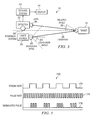
- FIGURE 5 is a graph 168 illustrating an example of modulation of laser beam 28.
- Graph 168 includes a strobe rate 170, a pulse rate 174, and a modulated pulse 178.
- Strobe rate 170 specifies the frames during which the laser fires. Tone Detection and Threshold 132 knows the strobe waveform.
- Pulse rate 174 is a continuous modulation synchronized to the detector frame rate.
- Modulated pulse 178 is the waveform that directly controls the laser firing circuitry.
- FIGURE 6 illustrates an example of a method of detecting target 14 with OA sensor system 10.
- controller 48 receives a command at step 410 to enter an OA mode. The command may be input by user through GUI 44.
- controller 48 sets laser source 20 to generate laser beam 28 with a large beam divergence to allow for a wide-area search to be performed.
- Laser source generates laser beam 28 at step 414.
- Beam spoiler 24 directs laser beam 28 towards area 12 at step 418.
- Area 12 including target 14 reflects laser beam 28.
- Detectors 32 detect reflected laser beam 28 at step 422.
- Detector data analyzer 52 analyzes the reflected beam 28 at step 426.
- Histogram generator 56 may generate a histogram 50 representing an image of scene 12 to determine whether histogram 50 includes a signature of target 14, such as a frequency count that exceeds a particular threshold.
- Image processor 54 generates image data at step 430.
- GUI 44 generates an image from the image data at step 434.
- Location estimator 58 performs a location analysis at step 438. The location may be reported through GUI 44 in the form of GPS coordinates. After the location analysis, the method terminates.
- a technical advantage of one embodiment may be that a target is detected using a laser beam that is retro-reflected from the target. Retro-reflection may effectively and efficiently detect targets such as optical/electro-optical (O/EO) devices.
- targets such as optical/electro-optical (O/EO) devices.
- the target may indicate the presence of an explosive device. That is, the target need not be the explosive device itself, but may be an O/EO device, for example, binoculars, that may be associated with personnel planting an explosive device.
Landscapes
- Physics & Mathematics (AREA)
- General Physics & Mathematics (AREA)
- Immunology (AREA)
- Pathology (AREA)
- Analytical Chemistry (AREA)
- Biochemistry (AREA)
- General Health & Medical Sciences (AREA)
- Life Sciences & Earth Sciences (AREA)
- Health & Medical Sciences (AREA)
- Chemical & Material Sciences (AREA)
- Spectroscopy & Molecular Physics (AREA)
- Engineering & Computer Science (AREA)
- Computer Networks & Wireless Communication (AREA)
- Radar, Positioning & Navigation (AREA)
- Remote Sensing (AREA)
- Optical Radar Systems And Details Thereof (AREA)
Description
- This invention relates generally to the field of detection systems and more specifically to detecting a target using an optical augmentation sensor.
- Detection systems may be used to detect hazardous objects. For example, military personnel may use a detection system to detect bombs in enemy territory. Detection systems should detect hazardous objects in an efficient and effective manner. In certain situations, however, known detection systems fail to do so.
US2007/034776 discloses a system for detecting an optically augmented target using a laser source and an imager wherein the target is accompanied by threat ordnance. - In accordance with the present invention, disadvantages and problems associated with previous techniques for detecting targets may be reduced or eliminated.
- According to one embodiment of the present invention, detecting a target includes directing a laser beam towards an area and detecting the laser beam reflected from the area. Whether the received laser beam comprises an optically augmented reflection indicating retro-reflection from a target is determined. The target indicates presence of an explosive device. The target is detected if the received laser beam comprises the optically augmented reflection.
- Certain embodiments of the invention may provide one or more technical advantages. A technical advantage of one embodiment may be that a target is detected using a laser beam that is retro-reflected from the target. Retro-reflection may effectively and efficiently detect targets such as optical/electro-optical (O/EO) devices. Another technical advantage of one embodiment may be that the target may indicate the presence of an explosive device. That is, the target need not be the explosive device itself, but may be an O/EO device, for example, binoculars, that may be associated with personnel planting an explosive device.
- Certain embodiments of the invention may include none, some, or all of the above technical advantages. One or more other technical advantages may be readily apparent to one skilled in the art from the figures, descriptions, and claims included herein.
- For a more complete understanding of the present invention and its features and advantages, reference is now made to the following description, taken in conjunction with the accompanying drawings, in which:
-
FIGURE 1 illustrates an example of an optical augmentation (OA) sensor system operable to detect a target in an area; -
FIGURE 2 illustrates an example of a histogram that may be generated by the OA sensor system ofFIGURE 1 ; -
FIGURE 3 illustrates another example of an OA sensor system operable to detect a target in an area; -
FIGURE 4 illustrates an example of a control system that may be used with an OA sensor system; -
FIGURE 5 is a graph illustrating an example of the modulation of the laser beam from the laser source; and -
FIGURE 6 illustrates an example of a method of detecting a target that may be used by the OA sensor system ofFIGURE 1 . - Embodiments of the present invention and its advantages are best understood by referring to
FIGURES 1 through 6 of the drawings, like numerals being used for like and corresponding parts of the various drawings. -
FIGURE 1 illustrates an example of an optical augmentation (OA)sensor system 10 operable to detect atarget 14.OA sensor system 10 detectstarget 14 using alaser beam 28 that is retro-reflected fromtarget 14.Target 14 may indicate the presence of anexplosive device 16. - In the illustrated embodiment,
area 12 represents an area that may be scanned byOA sensor system 10. For example,area 12 represents an indoor or outdoor scene that includes one or more objects that can reflectlaser beam 28. Examples ofarea 12 include an airport, a residential or business building, wartime territory, and/or other suitable area. -
Target 14 indicates the presence of an explosive device, and may represent an optical or electro-optical (O/EO) device that a person withexplosive device 16 may use. Examples oftarget 14 include binoculars, telescopes, camcorders, cameras, or other suitable O/EO device. An O/EO device typically includes an aperture, optics, and a focal plane. The aperture allows light to enter the device. Optics focus the light and may include one or more lenses. The light forms an image at the focal plane. -
Explosive device 16 represents a device that includes an explosive charge, a detonator, and/or an initiation system, and is typically designed to destroy or incapacitate personnel or vehicles. For example,explosive device 16 may represent an improvised explosive device (IED). An explosive device may include other destructive, lethal, noxious, pyrotechnic, or incendiary material. For example, an explosive device may include shrapnel such as nails or ball bearings. -
OA sensor 10 includes alaser source 20, abeam spoiler 24,detectors 32, acontrol system 40, and adisplay 44.Laser source 20 generates alaser beam 28. Examples oflaser source 20 include a laser designator, a Multiple Integrated Laser Engagement System (MILES), a gas continuous wave laser generator (such as a helium neon (HeNe) laser generator), and/or other suitable laser generator. A dispersive optic (such as a lens, holographic diffuser, or other dispersive optic) may illuminate the field of view ofdetectors 32. -
Beam spoiler 24 filters higher order components oflaser beam 28. -
Laser source 20 may be modulated at, for example, approximately one-half the frame rate ofdetectors 32. - Modulating
laser source 20 may increase the signal-to-noise ratio of the return fromtarget 14. The modulation may allowsystem 10 to reject transient signals (such as clutter) that do not oscillate according to the transmitted modulation. A tone detection and threshold operation can be accomplished using any suitable technique, such as single-frequency tone detection and Fourier analysis. -
Laser beam 28 may have any suitable wavelength, for example, a wavelength of approximately 0.8 micrometers (µm) to 1.6 µm, for example approximately 0.86, 0.90, 1.1, or 1.5 µm.Laser beam 28 may have any suitable divergence, for example, a divergence in the range of less than 10 millirads, for example, less than 8, 7, 2, 1, or 0.5 millirads or less than 200 microrads. -
Laser beam 28 can retro-reflect fromtarget 14 comprising an O/EO device. For example,laser beam 28 passes through the aperture of the O/EO device. A reflective area of the device, such as focal plane, reflectslaser beam 28. Optics of the device optically augments thereflected laser beam 28.Laser beam 28 retro-reflected fromtarget 14 yields a particular laser signature that identifiestarget 14. -
Detectors 32 detectlaser beam 28 reflected fromarea 12, which may includelaser beam 28 retro-reflected fromtarget 14. Adetector 32 may be a camera such as charge-coupled device (CCD) camera.Detectors 32 may detect any suitable wavelengths, for example, infrared, visible, or ultraviolet wavelengths. Adetector 32 may have afilter 38 that filters light to select wavelengths that enterdetector 32.Detector 32 may have a bandpass filter that reduces ambient illumination in non-illuminated spectral bands. - In one embodiment, a camera may have a field of view of 20 degrees or less. The camera may be disposed on a movement system that points the camera in different directions. Examples of movement systems include gimbal and pan/tilt platforms.
- In one embodiment,
detectors 32 include a detection camera and an interrogation camera. The detection camera is used first for wide area detection. If asuspicious target 14 is detected by the detection camera, the interrogation camera is used to detect human activity neartarget 14. In the illustrated embodiment, near-infrared (near-IR)camera 34 operates as the detection camera, andthermal camera 36 operates as the interrogation camera. - In one embodiment, the wavelengths of
laser beam 28 may be selected and/or set to match the wavelengths detectable bydetectors 32. For example, a wavelength between 600 nanometers and 1 micron, for example, approximately 900 nanometers may be used with a charge-coupled device (CCD) camera. A wavelength between 8 and 12 microns, for example, approximately 10 microns may be used with a thermal camera. In one embodiment,detectors 32 may be selected and/or set to detect the wavelength oflaser beam 28. In one embodiment,detectors 32 may have boresights with fields of view that match the beam divergence oflaser beam 28. -
Control system 40 includes acontroller 48, and adetector data processor 52.GUI 44 receives input (such as commands) from a user, and reports output to the user.Controller 48 controls the operation oflaser source 20 and/ordetectors 32, and may do so in response to commands fromGUI 44.Controller 48 may control the wavelength and/or beam divergence oflaser beam 28.Controller 48 may also control the wavelength detected bydetectors 32 and/or the azimuth (AZ) and/or elevation (EL) angles ofdetectors 32. -
Detector data analyzer 52 analyzes data received fromdetectors 32.Detector data analyzer 52 includes animage processor 54, ahistogram generator 56, and alocation estimator 58.Image processor 54 generates image data from detector signals from one ormore detectors 32. The image data is then sent to display 44 to generate animage 46 representingarea 12. Display may comprise a display of a computer.Image 46 may include a portion that representstarget 14. -
Histogram generator 56 generates a histogram that representsimage 46. A histogram may record frequency counts at each grayscale value ofimage 46. For example, for each grayscale value, the histogram may record the number of pixels that have that value. An example of a histogram is described in more detail with reference toFIGURE 2 . The laser signature oftarget 14 may manifest itself in a histogram. -
Location estimator 58 estimates the location oftarget 14 from the detector signals.Location estimator 58 may estimate the location in any suitable manner. For example,location estimator 58 may estimate the distance from the intensity of reflectedlaser beam 28, and the angle from the AZ/EL angle of reflectedlaser beam 28. - A component of
system 10 may include an interface, logic, memory, and/or other suitable element. An interface receives input, sends output, processes the input and/or output, and/or performs other suitable operation. An interface may comprise hardware and/or software. - Logic performs the operations of the component, for example, executes instructions to generate output from input. Logic may include hardware, software, and/or other logic, and may be stored in computer-readable storage medium. Certain logic, such as a processor, may manage the operation of a component. Examples of a processor include one or more computers, one or more microprocessors, one or more applications, and/or other logic.
- A memory stores information. A memory may comprise computer memory (for example, Random Access Memory (RAM) or Read Only Memory (ROM)), mass storage media (for example, a hard disk), removable storage media (for example, a Compact Disk (CD) or a Digital Video Disk (DVD)), database and/or network storage (for example, a server), and/or other computer-readable medium.
- Modifications, additions, or omissions may be made to
system 10 without departing from the scope of the invention. The components ofsystem 10 may be integrated or separated. Moreover, the operations ofsystem 10 may be performed by more, fewer, or other components. For example, the operations ofcontroller 48 anddetector data processor 52 may be performed by one component, or the operations ofGUI 44 may be performed by more than one component. Additionally, operations ofsystem 10 may be performed using any suitable logic comprising software, hardware, and/or other logic. As used in this document, "each" refers to each member of a set or each member of a subset of a set. -
FIGURE 2 illustrates an example of ahistogram 50 ofarea 12. In the illustrated embodiment, the x-axis represents grayscale values, and the y-axis represents frequency counts of a particular grayscale value, such as the number of pixels that have the value. -
Threshold 60 represents a minimum frequency count that is associated withbeam 28 retro-reflected fromtarget 14 and detected by adetector 32 as an optically augmented (OA) return. A frequency count abovethreshold 60 is designated as an OA return, and may indicate the presence oftarget 14. -
Histogram 50 includes frequency counts that representbackground 64, glints 68, and anOA return 72. Background counts 64 represent the background, and may typically be towards the darker end of the grayscale. Glints 62 may be towards the lighter end of the grayscale, and may be underthreshold 60. OA returns 72 are typically towards the lighter end of the grayscale and exceedthreshold 60. -
FIGURE 3 illustrates another example of anOA sensor system 10 operable to detecttarget 14.OA sensor 10 includeslaser source 20,detector 32,control system 40, anddisplay 44 coupled as shown. - In the illustrated example,
laser source 20 includes adispersive optic 80 that disperseslaser beam 28 through adispersion angle 84 measured from the axis ofdispersive optic 80. Examples ofdispersive optic 80 include a lens, holographic diffuser, or other dispersive optic.Target 14 can reflectlight beam 28 received with arelative angle 86 measured from the lens axis oftarget 14. - In the illustrated example,
detector 32 includes alens 90 and amovement system 94. Lens focuses light towardsdetector 32.Movement system 94moves detector 32 and/orlaser source 20 to pointdetector 32 and/orlaser source 20 in different directions. Examples ofmovement system 94 include gimbal and pan/tilt platforms. -
FIGURE 4 illustrates an example of acontrol system 40 that may be used with anOA sensor system 10. In the illustrated embodiment,OA sensor 10 includeslaser source 20, atimer 110,camera 34, an Inertial Measurement Unit (IMU)system 114,control system 40, anddisplay 44 coupled as shown. - In the illustrated embodiment,
timer 110 is used to modulatelaser source 20.Laser source 20 may be modulated in any suitable manner. An example of modulation is described with reference toFIGURE 5 .IMU system 114 establishes orientation angles ofcamera 34 that describe the rotation ofcamera 34 with respect to the ground. - In the illustrated embodiment,
control system 40 includes an interface controller/interrupthandler 120, aframe buffer 124, astabilizer 128, a tone detection andthreshold 132, asegmenter 136, an association and M ofN filter 140, atracking module 144, and apersistence queue 148. - Interface controller/interrupt
handler 120 receives timing signals fromtimer 110, image signals fromcamera 34, and IMU signals fromIMU system 114. Interface controller/interrupthandler 120 sends image data generated from the image signals to framebuffer 124, and sends IMU data generated from the IMU signals tostabilizer 128.Frame buffer 124 buffers the image data. -
Stabilizer 128 stabilizes the image data with respect to the ground according to the IMU data.Stabilizer 128 sends the stabilized image data to tone detection andthreshold 132, association and M ofN filter 140, and/ortracking module 144. - Tone detection and
threshold 132 may filter the image data for reflections oscillating at the same frequency as the transmitted source, and may reject weak or off-frequency oscillations that do not meet a specified threshold.Segmenter 136 segments the detected targets in the image data into image data points (pixels) for output to the association and M of N filter. Association and M ofN filter 140 merges individual image data point (pixels) into target detections.Tracking module 144 tracks target detections across multiple sets of image data.Persistence queue 148 discards tracks that have not been observed within a certain number of recent frames. -
FIGURE 5 is agraph 168 illustrating an example of modulation oflaser beam 28.Graph 168 includes astrobe rate 170, apulse rate 174, and a modulated pulse 178.Strobe rate 170 specifies the frames during which the laser fires. Tone Detection andThreshold 132 knows the strobe waveform.Pulse rate 174 is a continuous modulation synchronized to the detector frame rate. Modulated pulse 178 is the waveform that directly controls the laser firing circuitry. -
FIGURE 6 illustrates an example of a method of detectingtarget 14 withOA sensor system 10. In the method,controller 48 receives a command atstep 410 to enter an OA mode. The command may be input by user throughGUI 44. In the OA mode,controller 48sets laser source 20 to generatelaser beam 28 with a large beam divergence to allow for a wide-area search to be performed. Laser source generateslaser beam 28 atstep 414.Beam spoiler 24 directslaser beam 28 towardsarea 12 atstep 418.Area 12 includingtarget 14 reflectslaser beam 28. -
Detectors 32 detect reflectedlaser beam 28 atstep 422.Detector data analyzer 52 analyzes the reflectedbeam 28 atstep 426.Histogram generator 56 may generate ahistogram 50 representing an image ofscene 12 to determine whetherhistogram 50 includes a signature oftarget 14, such as a frequency count that exceeds a particular threshold. -
Image processor 54 generates image data atstep 430.GUI 44 generates an image from the image data atstep 434.Location estimator 58 performs a location analysis atstep 438. The location may be reported throughGUI 44 in the form of GPS coordinates. After the location analysis, the method terminates. - Modifications, additions, or omissions may be made to the method without departing from the scope of the invention. The method may include more, fewer, or other steps. Additionally, steps may be performed in any suitable order.
- Certain embodiments of the invention may provide one or more technical advantages. A technical advantage of one embodiment may be that a target is detected using a laser beam that is retro-reflected from the target. Retro-reflection may effectively and efficiently detect targets such as optical/electro-optical (O/EO) devices. Another technical advantage of one embodiment may be that the target may indicate the presence of an explosive device. That is, the target need not be the explosive device itself, but may be an O/EO device, for example, binoculars, that may be associated with personnel planting an explosive device.
- Although this disclosure has been described in terms of certain embodiments, alterations and permutations of the embodiments will be apparent to those skilled in the art. Accordingly, the above description of the embodiments does not constrain this disclosure. Other changes, substitutions, and alterations are possible without departing from the scope of this disclosure, as defined by the following claims.
Claims (14)
- A method for detecting a target (14), comprising:directing a laser beam (28) towards an area (12);detecting the laser beam (28) reflected from the area (12);determining whether the received laser beam comprises an optically augmented reflection indicating retro-reflection from a target (14),characterised in that the determining comprises:generating a histogram (50) representing a plurality of grayscale values of the area (12), the histogram (50) comprising a frequency count for each grayscale value;determining whether a frequency count of the histogram (50) is greater than a threshold (60); anddetermining that there is the optically augmented reflection if the frequency count of the histogram (50) is greater than the threshold (60); anddetecting the target (14) if the received laser beam comprises the optically augmented reflection.
- The method of Claim 1, wherein the laser beam (28) is retro-reflected from the target (14) by:reflecting the laser beam (28) from a reflective area of the target (14); andoptically augmenting the laser beam (28) using optics of the target (14).
- The method of Claim 1, further comprising:adjusting a wavelength of the laser beam (28) directed towards the area (12).
- The method of Claim 1, further comprising:adjusting a beam divergence of the laser beam (28) directed towards the area (12).
- The method of Claim 1, further comprising:adjusting a wavelength detectable by a detector (32) operable to detect the laser beam (28).
- The method of Claim 1, wherein detecting the laser beam (28) reflected from the area (12) further comprises:detecting the laser beam (28) using a camera (34) and/or a thermal camera (36).
- The method of Claim 1, further comprising:estimating a location of the target (14) according to the detected laser beam, preferably including estimating a distance and angle to the target using the intensity and the azimuth and/or elevation of the detected laser beam.
- A system (10) for detecting a target (14), comprising:a laser source (20) operable to:generate a laser beam (28) directed towards an area (12);one or more detectors (32) operable to:detect the laser beam (28) reflected from the area (12); and a control system (40)characterised in that the control system (40) is operable to:determine whether the received laser beam comprises an optically augmented reflection indicating retro-reflection from a target (14), the determining comprising:generating a histogram (50) representing a plurality of grayscale values of the area (12), the histogram (50) comprising a frequency count for each grayscale value;determining whether a frequency count of the histogram (50) is greater than a threshold (60); anddetermining that there is the optically augmented reflection if the frequency count of the histogram (50) is greater than the threshold (60); anddetect the target (14) if the received laser beam comprises the optically augmented reflection.
- The system of Claim 8, the control system (40) further operable to:adjust a wavelength of the laser beam (28) directed towards the area (12).
- The system of Claim 8, the control system (40) further operable to:adjust a beam divergence of the laser beam (28) directed towards the area (12).
- The system of Claim 8, the control system (40) further operable to:adjust a wavelength detectable by a detector (34) of the one or more detectors (32).
- The system of Claim 8, wherein the one or more detectors comprises a camera and/or a thermal camera.
- The system (10) of Claim 8, the control system (40) further operable to:estimate a location of the target (14) according to the detected laser beam, preferably including estimating a distance and angle to the target using the intensity and the azimuth and/or elevation of the detected laser beam.
- The system (10) of Claim 8, further comprising a movement system (94) operable to move a detector (32) of the one or more detectors (32).
Applications Claiming Priority (2)
| Application Number | Priority Date | Filing Date | Title |
|---|---|---|---|
| US12/053,665 US7978330B2 (en) | 2008-03-24 | 2008-03-24 | Detecting a target using an optical augmentation sensor |
| PCT/US2009/035647 WO2009151660A2 (en) | 2008-03-24 | 2009-03-02 | Detecting a target using an optical augmentation sensor |
Publications (2)
| Publication Number | Publication Date |
|---|---|
| EP2269090A2 EP2269090A2 (en) | 2011-01-05 |
| EP2269090B1 true EP2269090B1 (en) | 2015-08-05 |
Family
ID=41088561
Family Applications (1)
| Application Number | Title | Priority Date | Filing Date |
|---|---|---|---|
| EP09762956.2A Active EP2269090B1 (en) | 2008-03-24 | 2009-03-02 | Detecting a target using an optical augmentation sensor |
Country Status (3)
| Country | Link |
|---|---|
| US (1) | US7978330B2 (en) |
| EP (1) | EP2269090B1 (en) |
| WO (1) | WO2009151660A2 (en) |
Families Citing this family (10)
| Publication number | Priority date | Publication date | Assignee | Title |
|---|---|---|---|---|
| US8027029B2 (en) | 2007-11-07 | 2011-09-27 | Magna Electronics Inc. | Object detection and tracking system |
| AU2011285873B2 (en) | 2010-08-04 | 2015-07-09 | Trijicon, Inc. | Optical Sight |
| US8994819B2 (en) * | 2011-02-04 | 2015-03-31 | Raytheon Company | Integrated optical detection system |
| US9482617B2 (en) | 2012-06-07 | 2016-11-01 | Jeffrey M. Smith | Method for optical detection of surveillance and sniper personnel |
| US9400414B2 (en) | 2012-11-19 | 2016-07-26 | Raytheon Company | Methods and apparatus for imaging without retro-reflection using a tilted image plane and structured relay optic |
| US9535245B1 (en) | 2012-12-14 | 2017-01-03 | Raytheon Company | Methods and apparatus for deceiving optical augmentation |
| US9018575B2 (en) | 2012-12-14 | 2015-04-28 | Raytheon Company | Non-retroreflective optical threat detection system and methods having an imaging detector aligned with a tilted image plane to reconstruct an image from plural image slices |
| CN108663687B (en) * | 2017-03-27 | 2024-03-29 | 苏州优函信息科技有限公司 | Smooth surface imaging laser radar based on linear light source and area array camera and detection method |
| US11747480B2 (en) * | 2020-08-18 | 2023-09-05 | IntelliShot Holdings, Inc. | Automated threat detection and deterrence apparatus |
| US12076822B2 (en) * | 2020-09-16 | 2024-09-03 | T Bailey, Inc. | Welding tracking and/or motion system, device and/or process |
Citations (1)
| Publication number | Priority date | Publication date | Assignee | Title |
|---|---|---|---|---|
| US6665079B1 (en) * | 1999-03-24 | 2003-12-16 | Science & Engineering Associates, Inc. | Method and apparatus for locating electromagnetic imaging and detection systems/devices |
Family Cites Families (19)
| Publication number | Priority date | Publication date | Assignee | Title |
|---|---|---|---|---|
| US4234141A (en) * | 1970-03-10 | 1980-11-18 | The United States Of America As Represented By The Secretary Of The Army | Range gated retroreflective missile guidance system |
| US5449899A (en) * | 1971-10-21 | 1995-09-12 | Lockheed Sanders, Inc. | Apparatus and method for highlighting returns from optically augmented targets |
| DE2157672A1 (en) * | 1971-11-20 | 1973-05-24 | Messerschmitt Boelkow Blohm | ARRANGEMENT FOR THE STEERING OF AIRCRABTS BY USING A LASER |
| US4131791A (en) * | 1975-12-08 | 1978-12-26 | General Electric Company | Search and locate system |
| US5485012A (en) * | 1978-07-18 | 1996-01-16 | The United States Of America As Represented By The Secretary Of The Army | Method and apparatus for blind optical augmentation |
| US5018151A (en) * | 1981-05-29 | 1991-05-21 | Seaton Norman T | Laser control apparatus and method for frequency offset phase locking and the minimizing of retro-reflection effects |
| FR2602346B1 (en) * | 1986-08-01 | 1988-09-16 | Thomson Csf | LOCATION SYSTEM USING A LASER BEAM RETROREFLECTOR AND MODULATOR ASSEMBLY |
| US6166803A (en) * | 1987-03-20 | 2000-12-26 | The United States Of America As Represented By The Secretary Of The Army | Imaging simplified laser pointing (ISLAPS)--A system modification/improvement |
| IL109426A (en) * | 1994-04-25 | 1999-05-09 | Glaser Inbari Isaia | Rapid random-access optical scanner and method |
| US5644386A (en) * | 1995-01-11 | 1997-07-01 | Loral Vought Systems Corp. | Visual recognition system for LADAR sensors |
| US5987159A (en) * | 1996-09-24 | 1999-11-16 | Cognex Corporation | System or method for detecting defect within a semi-opaque enclosure |
| US6031601A (en) * | 1998-07-08 | 2000-02-29 | Trimble Navigation Limited | Code-space optical electronic distance meter |
| WO2001072215A1 (en) * | 2000-03-28 | 2001-10-04 | Board Of Regents, The University Of Texas System | Enhancing contrast in biological imaging |
| CA2405274A1 (en) * | 2000-04-07 | 2001-10-18 | The Regents Of The University Of California | Remotely-interrogated high data rate free space laser communications link |
| US20040033472A1 (en) * | 2002-08-14 | 2004-02-19 | Deepak Varshneya | All-optical precision gunnery simulation (PGS) method and system |
| EP1728068B1 (en) * | 2004-02-26 | 2016-11-02 | BAE SYSTEMS Information and Electronic Systems Integration, Inc. | Improved active search sensor and a method of detection using non-specular reflections |
| US7583863B2 (en) * | 2004-05-10 | 2009-09-01 | Avago Technologies General Ip (Singapore) Pte. Ltd. | Method and system for wavelength-dependent imaging and detection using a hybrid filter |
| US7360703B2 (en) * | 2004-09-23 | 2008-04-22 | Ut-Battelle, Llc | Laser scanning system for object monitoring |
| US7468695B1 (en) * | 2007-07-19 | 2008-12-23 | Raytheon Company | GPS attitude determination system and method using baseline extension |
-
2008
- 2008-03-24 US US12/053,665 patent/US7978330B2/en active Active
-
2009
- 2009-03-02 WO PCT/US2009/035647 patent/WO2009151660A2/en not_active Ceased
- 2009-03-02 EP EP09762956.2A patent/EP2269090B1/en active Active
Patent Citations (1)
| Publication number | Priority date | Publication date | Assignee | Title |
|---|---|---|---|---|
| US6665079B1 (en) * | 1999-03-24 | 2003-12-16 | Science & Engineering Associates, Inc. | Method and apparatus for locating electromagnetic imaging and detection systems/devices |
Also Published As
| Publication number | Publication date |
|---|---|
| US20090237668A1 (en) | 2009-09-24 |
| US7978330B2 (en) | 2011-07-12 |
| WO2009151660A2 (en) | 2009-12-17 |
| EP2269090A2 (en) | 2011-01-05 |
| WO2009151660A3 (en) | 2010-04-01 |
Similar Documents
| Publication | Publication Date | Title |
|---|---|---|
| US7978330B2 (en) | Detecting a target using an optical augmentation sensor | |
| US8994819B2 (en) | Integrated optical detection system | |
| CA2554955C (en) | Gated imaging | |
| US10823825B2 (en) | System and method for wide-area surveillance | |
| Repasi et al. | Advanced short-wavelength infrared range-gated imaging for ground applications in monostatic and bistatic configurations | |
| Christnacher et al. | Optical and acoustical UAV detection | |
| KR100524337B1 (en) | Method and apparatus for aircraft protection against missile threats | |
| US5796474A (en) | Projectile tracking system | |
| US5345304A (en) | Integrated LADAR/FLIR sensor | |
| US20090260511A1 (en) | Target acquisition and tracking system | |
| US8731240B1 (en) | System and method for optics detection | |
| JPH11153398A (en) | Dichronism performance tracking device | |
| US20130099096A1 (en) | Flash detection and laser response system | |
| Tholl | Review and prospects of optical countermeasure technologies | |
| US8351659B2 (en) | Eye detection system | |
| US8169597B2 (en) | Method and apparatus for laser return characterization in a countermeasures system | |
| Caplan | Requirements for laser countermeasures against imaging seekers | |
| US20150253253A1 (en) | Method for optical detection of surveillance and sniper personnel | |
| Steinvall | The potential role of lasers in combating UAVs, part 1: detection, tracking, and recognition of UAVs | |
| Larochelle et al. | Two generations of Canadian active imaging systems: ALBEDOS and ELVISS | |
| Sjöqvist et al. | Target discrimination strategies in optics detection | |
| Christnacher et al. | UAV detection: a review of ISL researches over the past ten years | |
| Boehrer et al. | Laser warning and pointed optics detection using an event camera | |
| US7781721B1 (en) | Active electro-optic missile warning system | |
| US7414702B1 (en) | Reverse logic optical acquisition system and method |
Legal Events
| Date | Code | Title | Description |
|---|---|---|---|
| PUAI | Public reference made under article 153(3) epc to a published international application that has entered the european phase |
Free format text: ORIGINAL CODE: 0009012 |
|
| 17P | Request for examination filed |
Effective date: 20101022 |
|
| AK | Designated contracting states |
Kind code of ref document: A2 Designated state(s): AT BE BG CH CY CZ DE DK EE ES FI FR GB GR HR HU IE IS IT LI LT LU LV MC MK MT NL NO PL PT RO SE SI SK TR |
|
| AX | Request for extension of the european patent |
Extension state: AL BA RS |
|
| DAX | Request for extension of the european patent (deleted) | ||
| 17Q | First examination report despatched |
Effective date: 20120327 |
|
| REG | Reference to a national code |
Ref country code: DE Ref legal event code: R079 Ref document number: 602009032677 Country of ref document: DE Free format text: PREVIOUS MAIN CLASS: G01S0007480000 Ipc: G01J0003360000 |
|
| GRAP | Despatch of communication of intention to grant a patent |
Free format text: ORIGINAL CODE: EPIDOSNIGR1 |
|
| RIC1 | Information provided on ipc code assigned before grant |
Ipc: G01S 7/48 20060101ALN20150224BHEP Ipc: G01S 17/89 20060101ALI20150224BHEP Ipc: G01N 21/55 20140101ALI20150224BHEP Ipc: G01N 21/3563 20140101ALI20150224BHEP Ipc: G01J 3/36 20060101AFI20150224BHEP |
|
| INTG | Intention to grant announced |
Effective date: 20150324 |
|
| GRAS | Grant fee paid |
Free format text: ORIGINAL CODE: EPIDOSNIGR3 |
|
| GRAA | (expected) grant |
Free format text: ORIGINAL CODE: 0009210 |
|
| AK | Designated contracting states |
Kind code of ref document: B1 Designated state(s): AT BE BG CH CY CZ DE DK EE ES FI FR GB GR HR HU IE IS IT LI LT LU LV MC MK MT NL NO PL PT RO SE SI SK TR |
|
| REG | Reference to a national code |
Ref country code: GB Ref legal event code: FG4D |
|
| REG | Reference to a national code |
Ref country code: CH Ref legal event code: EP |
|
| REG | Reference to a national code |
Ref country code: AT Ref legal event code: REF Ref document number: 740984 Country of ref document: AT Kind code of ref document: T Effective date: 20150815 |
|
| REG | Reference to a national code |
Ref country code: IE Ref legal event code: FG4D |
|
| REG | Reference to a national code |
Ref country code: DE Ref legal event code: R096 Ref document number: 602009032677 Country of ref document: DE |
|
| REG | Reference to a national code |
Ref country code: AT Ref legal event code: MK05 Ref document number: 740984 Country of ref document: AT Kind code of ref document: T Effective date: 20150805 |
|
| REG | Reference to a national code |
Ref country code: LT Ref legal event code: MG4D |
|
| REG | Reference to a national code |
Ref country code: NL Ref legal event code: MP Effective date: 20150805 |
|
| PG25 | Lapsed in a contracting state [announced via postgrant information from national office to epo] |
Ref country code: GR Free format text: LAPSE BECAUSE OF FAILURE TO SUBMIT A TRANSLATION OF THE DESCRIPTION OR TO PAY THE FEE WITHIN THE PRESCRIBED TIME-LIMIT Effective date: 20151106 Ref country code: NO Free format text: LAPSE BECAUSE OF FAILURE TO SUBMIT A TRANSLATION OF THE DESCRIPTION OR TO PAY THE FEE WITHIN THE PRESCRIBED TIME-LIMIT Effective date: 20151105 Ref country code: FI Free format text: LAPSE BECAUSE OF FAILURE TO SUBMIT A TRANSLATION OF THE DESCRIPTION OR TO PAY THE FEE WITHIN THE PRESCRIBED TIME-LIMIT Effective date: 20150805 Ref country code: LV Free format text: LAPSE BECAUSE OF FAILURE TO SUBMIT A TRANSLATION OF THE DESCRIPTION OR TO PAY THE FEE WITHIN THE PRESCRIBED TIME-LIMIT Effective date: 20150805 Ref country code: LT Free format text: LAPSE BECAUSE OF FAILURE TO SUBMIT A TRANSLATION OF THE DESCRIPTION OR TO PAY THE FEE WITHIN THE PRESCRIBED TIME-LIMIT Effective date: 20150805 |
|
| REG | Reference to a national code |
Ref country code: FR Ref legal event code: PLFP Year of fee payment: 8 |
|
| PG25 | Lapsed in a contracting state [announced via postgrant information from national office to epo] |
Ref country code: ES Free format text: LAPSE BECAUSE OF FAILURE TO SUBMIT A TRANSLATION OF THE DESCRIPTION OR TO PAY THE FEE WITHIN THE PRESCRIBED TIME-LIMIT Effective date: 20150805 Ref country code: IS Free format text: LAPSE BECAUSE OF FAILURE TO SUBMIT A TRANSLATION OF THE DESCRIPTION OR TO PAY THE FEE WITHIN THE PRESCRIBED TIME-LIMIT Effective date: 20151205 Ref country code: AT Free format text: LAPSE BECAUSE OF FAILURE TO SUBMIT A TRANSLATION OF THE DESCRIPTION OR TO PAY THE FEE WITHIN THE PRESCRIBED TIME-LIMIT Effective date: 20150805 Ref country code: SE Free format text: LAPSE BECAUSE OF FAILURE TO SUBMIT A TRANSLATION OF THE DESCRIPTION OR TO PAY THE FEE WITHIN THE PRESCRIBED TIME-LIMIT Effective date: 20150805 Ref country code: PL Free format text: LAPSE BECAUSE OF FAILURE TO SUBMIT A TRANSLATION OF THE DESCRIPTION OR TO PAY THE FEE WITHIN THE PRESCRIBED TIME-LIMIT Effective date: 20150805 Ref country code: PT Free format text: LAPSE BECAUSE OF FAILURE TO SUBMIT A TRANSLATION OF THE DESCRIPTION OR TO PAY THE FEE WITHIN THE PRESCRIBED TIME-LIMIT Effective date: 20151207 Ref country code: HR Free format text: LAPSE BECAUSE OF FAILURE TO SUBMIT A TRANSLATION OF THE DESCRIPTION OR TO PAY THE FEE WITHIN THE PRESCRIBED TIME-LIMIT Effective date: 20150805 |
|
| PG25 | Lapsed in a contracting state [announced via postgrant information from national office to epo] |
Ref country code: NL Free format text: LAPSE BECAUSE OF FAILURE TO SUBMIT A TRANSLATION OF THE DESCRIPTION OR TO PAY THE FEE WITHIN THE PRESCRIBED TIME-LIMIT Effective date: 20150805 |
|
| PG25 | Lapsed in a contracting state [announced via postgrant information from national office to epo] |
Ref country code: EE Free format text: LAPSE BECAUSE OF FAILURE TO SUBMIT A TRANSLATION OF THE DESCRIPTION OR TO PAY THE FEE WITHIN THE PRESCRIBED TIME-LIMIT Effective date: 20150805 Ref country code: DK Free format text: LAPSE BECAUSE OF FAILURE TO SUBMIT A TRANSLATION OF THE DESCRIPTION OR TO PAY THE FEE WITHIN THE PRESCRIBED TIME-LIMIT Effective date: 20150805 Ref country code: SK Free format text: LAPSE BECAUSE OF FAILURE TO SUBMIT A TRANSLATION OF THE DESCRIPTION OR TO PAY THE FEE WITHIN THE PRESCRIBED TIME-LIMIT Effective date: 20150805 Ref country code: IT Free format text: LAPSE BECAUSE OF FAILURE TO SUBMIT A TRANSLATION OF THE DESCRIPTION OR TO PAY THE FEE WITHIN THE PRESCRIBED TIME-LIMIT Effective date: 20150805 Ref country code: CZ Free format text: LAPSE BECAUSE OF FAILURE TO SUBMIT A TRANSLATION OF THE DESCRIPTION OR TO PAY THE FEE WITHIN THE PRESCRIBED TIME-LIMIT Effective date: 20150805 |
|
| REG | Reference to a national code |
Ref country code: DE Ref legal event code: R097 Ref document number: 602009032677 Country of ref document: DE |
|
| PG25 | Lapsed in a contracting state [announced via postgrant information from national office to epo] |
Ref country code: RO Free format text: LAPSE BECAUSE OF FAILURE TO SUBMIT A TRANSLATION OF THE DESCRIPTION OR TO PAY THE FEE WITHIN THE PRESCRIBED TIME-LIMIT Effective date: 20150805 |
|
| PLBE | No opposition filed within time limit |
Free format text: ORIGINAL CODE: 0009261 |
|
| STAA | Information on the status of an ep patent application or granted ep patent |
Free format text: STATUS: NO OPPOSITION FILED WITHIN TIME LIMIT |
|
| 26N | No opposition filed |
Effective date: 20160509 |
|
| PG25 | Lapsed in a contracting state [announced via postgrant information from national office to epo] |
Ref country code: SI Free format text: LAPSE BECAUSE OF FAILURE TO SUBMIT A TRANSLATION OF THE DESCRIPTION OR TO PAY THE FEE WITHIN THE PRESCRIBED TIME-LIMIT Effective date: 20150805 Ref country code: BE Free format text: LAPSE BECAUSE OF NON-PAYMENT OF DUE FEES Effective date: 20160331 |
|
| PG25 | Lapsed in a contracting state [announced via postgrant information from national office to epo] |
Ref country code: MC Free format text: LAPSE BECAUSE OF FAILURE TO SUBMIT A TRANSLATION OF THE DESCRIPTION OR TO PAY THE FEE WITHIN THE PRESCRIBED TIME-LIMIT Effective date: 20150805 Ref country code: LU Free format text: LAPSE BECAUSE OF FAILURE TO SUBMIT A TRANSLATION OF THE DESCRIPTION OR TO PAY THE FEE WITHIN THE PRESCRIBED TIME-LIMIT Effective date: 20160302 |
|
| REG | Reference to a national code |
Ref country code: CH Ref legal event code: PL |
|
| REG | Reference to a national code |
Ref country code: IE Ref legal event code: MM4A |
|
| PG25 | Lapsed in a contracting state [announced via postgrant information from national office to epo] |
Ref country code: BE Free format text: LAPSE BECAUSE OF FAILURE TO SUBMIT A TRANSLATION OF THE DESCRIPTION OR TO PAY THE FEE WITHIN THE PRESCRIBED TIME-LIMIT Effective date: 20150805 |
|
| PG25 | Lapsed in a contracting state [announced via postgrant information from national office to epo] |
Ref country code: LI Free format text: LAPSE BECAUSE OF NON-PAYMENT OF DUE FEES Effective date: 20160331 Ref country code: IE Free format text: LAPSE BECAUSE OF NON-PAYMENT OF DUE FEES Effective date: 20160302 Ref country code: CH Free format text: LAPSE BECAUSE OF NON-PAYMENT OF DUE FEES Effective date: 20160331 |
|
| REG | Reference to a national code |
Ref country code: FR Ref legal event code: PLFP Year of fee payment: 9 |
|
| PG25 | Lapsed in a contracting state [announced via postgrant information from national office to epo] |
Ref country code: MT Free format text: LAPSE BECAUSE OF FAILURE TO SUBMIT A TRANSLATION OF THE DESCRIPTION OR TO PAY THE FEE WITHIN THE PRESCRIBED TIME-LIMIT Effective date: 20150805 |
|
| REG | Reference to a national code |
Ref country code: FR Ref legal event code: PLFP Year of fee payment: 10 |
|
| PG25 | Lapsed in a contracting state [announced via postgrant information from national office to epo] |
Ref country code: CY Free format text: LAPSE BECAUSE OF FAILURE TO SUBMIT A TRANSLATION OF THE DESCRIPTION OR TO PAY THE FEE WITHIN THE PRESCRIBED TIME-LIMIT Effective date: 20150805 Ref country code: HU Free format text: LAPSE BECAUSE OF FAILURE TO SUBMIT A TRANSLATION OF THE DESCRIPTION OR TO PAY THE FEE WITHIN THE PRESCRIBED TIME-LIMIT; INVALID AB INITIO Effective date: 20090302 |
|
| PG25 | Lapsed in a contracting state [announced via postgrant information from national office to epo] |
Ref country code: TR Free format text: LAPSE BECAUSE OF FAILURE TO SUBMIT A TRANSLATION OF THE DESCRIPTION OR TO PAY THE FEE WITHIN THE PRESCRIBED TIME-LIMIT Effective date: 20150805 Ref country code: MT Free format text: LAPSE BECAUSE OF FAILURE TO SUBMIT A TRANSLATION OF THE DESCRIPTION OR TO PAY THE FEE WITHIN THE PRESCRIBED TIME-LIMIT Effective date: 20160331 Ref country code: MK Free format text: LAPSE BECAUSE OF FAILURE TO SUBMIT A TRANSLATION OF THE DESCRIPTION OR TO PAY THE FEE WITHIN THE PRESCRIBED TIME-LIMIT Effective date: 20150805 |
|
| PG25 | Lapsed in a contracting state [announced via postgrant information from national office to epo] |
Ref country code: BG Free format text: LAPSE BECAUSE OF FAILURE TO SUBMIT A TRANSLATION OF THE DESCRIPTION OR TO PAY THE FEE WITHIN THE PRESCRIBED TIME-LIMIT Effective date: 20150805 |
|
| P01 | Opt-out of the competence of the unified patent court (upc) registered |
Effective date: 20230530 |
|
| PGFP | Annual fee paid to national office [announced via postgrant information from national office to epo] |
Ref country code: GB Payment date: 20260219 Year of fee payment: 18 |
|
| PGFP | Annual fee paid to national office [announced via postgrant information from national office to epo] |
Ref country code: DE Payment date: 20260219 Year of fee payment: 18 |
|
| PGFP | Annual fee paid to national office [announced via postgrant information from national office to epo] |
Ref country code: FR Payment date: 20260220 Year of fee payment: 18 |