EP2268455B1 - Wire guide for an automatic staple gun - Google Patents
Wire guide for an automatic staple gun Download PDFInfo
- Publication number
- EP2268455B1 EP2268455B1 EP09716995.7A EP09716995A EP2268455B1 EP 2268455 B1 EP2268455 B1 EP 2268455B1 EP 09716995 A EP09716995 A EP 09716995A EP 2268455 B1 EP2268455 B1 EP 2268455B1
- Authority
- EP
- European Patent Office
- Prior art keywords
- wire guide
- cam
- housing
- switch
- guide apparatus
- Prior art date
- Legal status (The legal status is an assumption and is not a legal conclusion. Google has not performed a legal analysis and makes no representation as to the accuracy of the status listed.)
- Not-in-force
Links
- 230000000994 depressogenic effect Effects 0.000 description 2
Images


Classifications
-
- B—PERFORMING OPERATIONS; TRANSPORTING
- B25—HAND TOOLS; PORTABLE POWER-DRIVEN TOOLS; MANIPULATORS
- B25C—HAND-HELD NAILING OR STAPLING TOOLS; MANUALLY OPERATED PORTABLE STAPLING TOOLS
- B25C5/00—Manually operated portable stapling tools; Hand-held power-operated stapling tools; Staple feeding devices therefor
- B25C5/06—Manually operated portable stapling tools; Hand-held power-operated stapling tools; Staple feeding devices therefor without provision for bending the ends of the staples on to the work
Definitions
- the invention is directed to the field of automatic staple guns, and more particularly to a wire guide element for positioning a staple in the gun with respect to a wire or cable to be stapled.
- Staple guns are well known hand-held tools adapted to drive staples into a workpiece.
- Arrow Fastener Company manufactures and sells numerous models of such devices, including the non-powered staple gun sold under the T-50® brand name, and more recently introduced powered models, such as the cordless CT-50TM.
- a wire guide for a staple gun, as disclosed for example in U.S. Patent No. 5,884,829 , assigned to the Arrow Fastener Company and incorporated herein by reference.
- a wire guide is an element having a surface that fits around a wire or cable, positioning the staple gun so that the staple is driven reliably over the wire or cable to attach it to the work piece. Surfaces on either side of the wire or cable are typically positioned against the surface to be stapled.
- European Patent Application No. 1095740 shows a staple gun wire guide driven by a sliding switch arrangement.
- US Patent Application No. US2007/0039994 discloses a stapler with a guide which is rotated into position by a gear wheel.
- the safety element is a planar vertically oriented element that protrudes from the bottom of the gun in front of the driver. The planar element actuates a switch, so that the gun can fire only when the safety is fully depressed, i.e., when the bottom of the gun is positioned against a surface to be stapled.
- Both the LED and safety are advantageously positioned in front of the staple driver, so as not to interfere with the operation of the gun, and especially with the operation of the staple driver.
- To provide a wire guide in combination with these elements poses a technical challenge because the available space in front of the staple driver is limited.
- one object of the invention is to provide a wire guide for a staple gun in a low profile housing at the front end thereof, that can be retracted by the user and which can be combined with other elements, such as an LED and a safety, in a space-saving manner.
- the invention is a wire guide apparatus as set out in claim 1 appended hereto.
- the staple gun is provided with a substantially planar safety element having an aperture through which the cam shaft passes, the aperture being elongated so that the safety element can slide in the vertical direction in the housing.
- the housing is provided with a light emitting diode.
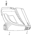
- Fig.1 is a perspective view of a staple gun incorporating a wire guide apparatus according to the invention.
- Fig. 2 is a detail view of the wire guide housing.
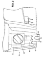
- Fig. 3 is a detail view of the wire guide housing with the wire guide in the extended position.
- Fig. 4 is a detail view of internal elements of the wire guide camming mechanism.
- Fig. 5 is a detail view of internal elements of the wire guide camming mechanism in the extended and locked position.
- the handle is at the top of the device, and the direction toward the top is “up.”
- the staple driver (not shown) is oriented vertically, located toward the "front” of the gun; staples come out of the “bottom” of the staple gun, and the direction toward the bottom is “down,” etc.
- the staple gun 10 includes insert 12, located at the front end of the staple gun at the bottom.
- the staple driver sometimes referred to as the "knife" (not shown), is a vertical element located behind the insert that drives the staples out of the gun when the trigger is actuated.
- insert 12 includes a housing 18, which may be provided with slots to guide a wire guide 14 and safety element 22.
- the housing also includes space for cam switch 20.
- the cam switch may be any shape provided that it can be configured to move wire guide 14.
- at least a portion of the cam switch is arcuately shaped, and the cam is seated in a correspondingly shaped arcuate recess in the housing.
- the switch can be circular and seated in a circular recess, as shown in Fig. 2 .
- the cam switch is rotatable between a first position and a second position, corresponding to respective first and second positions of wire guide 14, so that the wire guide is either not extended from the bottom of the staple gun, as shown in Fig. 2 , or extended from the bottom of the staple gun, and ready to be used.
- This enables convenient use of the staple gun without the wire guide, such as with nails (typically 5/8" nails), or with staples, in a context where it is not desired to staple cable or wire.
- the wire guide is set to a retracted position.
- the housing may have an open back and a central channel on the front of the housing to receive the cam switch 20 and a sub housing 52 holding an LED 50 in a compact low-profile manner.
- "Low profile” in this context means less than 25 mm, preferably less than 20 mm and most preferably less than 15 mm total height of the housing from back to front.
- the wire guide element 14 is substantially planar so that it can be accommodated in a low profile housing.
- the wire guide comprises a first cutout 36 (shown in Fig. 4 ) with an open end adapted to be positioned over a wire or cable when in use, and a second cutout 32 adapted to receive the cam 28.
- the second cutout has a closed surface 34 (seen in Fig. 4 ) on one side of the cam which prevents rotation of the cam past surface 34 in either clockwise or counterclockwise directions, while on the opposite side of the cam, the second cutout 32 has room to permit rotation of the cam 28.
- the side of the second cutout opposite the closed side is open, and the cam can be rotated a little more than 180 degrees from the first position to the second position.
- the closed surface 34 of the second cutout may be provided with rounded corners so that the cutout is slightly wider at the closed end than at the open end. This facilitates positioning the bearing surface 30 of the cam in the corners of the second cutout to perform a locking function as described below.
- a cam mechanism for a wire guide is illustrated in connection with Fig. 4 .
- the cam switch has been removed to reveal cam shaft 24, spring 26 and cam 28, which are assembled on back plate 120.
- the cam may have any shape suitable to the purpose, including the ovoid shape shown in the preferred embodiment of Fig. 4 .
- bearing surface 30 of the cam 28 is urged against the top surface of the second cutout 32.
- the cam is rotated a little past the longitudinal axis of the wire guide, so that the longitudinal axis of the cam forms a small angle with respect to the longitudinal axis of the wire guide 14, inclining slightly toward the closed side of the second cutout.
- a similar locking functionality is obtained in the second (extended) position of the wire guide, where the cam is rotated a little more than 180 degrees, so that bearing surface 30 of the cam is urged against the bottom surface of the second cutout.
- the wire guide cannot be moved by applying force in the direction of arrow F, unless the cam is moved again by moving cam switch 20. This is shown best in Fig. 5 .
- the locking mechanism is improved by widening the corners of the closed surface 34 in the second cutout, such as by rounding the corners.
- the dimensions of the second cutout are determined by how large a cam is required to make the wire guide protrude from the staple gun by the desired amount in the second position.
- the vertical height of the second cutout may be in a range of about 8.0 mm to about 11.0 mm, and the distance between the top and bottom walls at the closed end, i.e., at the widest point, may be about 0.1 mm to about 0.5 mm larger than the distance at the opposite, or open, side of the second cutout.
- the first cutout 36 may be formed with prongs 38 defining opposite sides of the first cutout.
- the distance between the two prongs defining the first cutout is not particularly critical, and may be, for example, in a range of about 6.0 mm to about 8.0 mm. In a working embodiment, a width of 7.0 mm was found to be suitable for this purpose.
- the distance from the top of the cutout to the bottom ends of the prongs is not limited. This distance may conveniently be in a range of about 5.0 to 7.0 mm, for example 6.2 mm.
- the top of the cutout may be any shape, such as arcuate shape. In the Figures, the top of the cutout is essentially in the shape of a semicircle.
- the staples ordinarily used with the CT-50 TM made by the Arrow Fastener Company will also be used with a model adapted with the wire guide according to the invention, and the size of the first cutout may be designed accordingly.
- the staple gun may be provided with a safety element 22 which is operatively connected to elements in the body of the gun in a known manner (not shown) so that the gun cannot fire unless the safety is depressed.
- safety 22 is provided with an aperture 44 through which cam shaft passes. The aperture is somewhat elongated, allowing the safety element to move up and down without affecting the wire guide. (Only a portion of aperture 44 is seen in Fig. 4 and Fig. 5 , because the view is obscured by the wire guide.)
- Fig. 2 depicts a preferred embodiment in which housing 18 is provided with a central channel which houses the cam switch 20, as well as LED sub housing 52, including LED 50, as well as accommodating the wire guide and cam elements described above. All of these elements can be provided in a low profile format, having a height less than 20 mm, preferably less than 15 mm, which permits the safety 22, the LED 50 and the wire guide 14 all to be positioned in close proximity to the staple driver.
Landscapes
- Engineering & Computer Science (AREA)
- Mechanical Engineering (AREA)
- Portable Nailing Machines And Staplers (AREA)
- Dovetailed Work, And Nailing Machines And Stapling Machines For Wood (AREA)
Description
- The invention is directed to the field of automatic staple guns, and more particularly to a wire guide element for positioning a staple in the gun with respect to a wire or cable to be stapled.
- Staple guns are well known hand-held tools adapted to drive staples into a workpiece. Arrow Fastener Company manufactures and sells numerous models of such devices, including the non-powered staple gun sold under the T-50® brand name, and more recently introduced powered models, such as the cordless CT-50™.
- It is known to provide a wire guide for a staple gun, as disclosed for example in
U.S. Patent No. 5,884,829 , assigned to the Arrow Fastener Company and incorporated herein by reference. A wire guide is an element having a surface that fits around a wire or cable, positioning the staple gun so that the staple is driven reliably over the wire or cable to attach it to the work piece. Surfaces on either side of the wire or cable are typically positioned against the surface to be stapled. European Patent Application No.1095740 shows a staple gun wire guide driven by a sliding switch arrangement. US Patent Application No.US2007/0039994 discloses a stapler with a guide which is rotated into position by a gear wheel. - As staple gun technology has advanced, a number of desirable features have been added. An LED positioned near the staple driver and adapted to directly illuminate the surface being stapled is very popular. It is also known to equip staple guns with passive safety features. In the CT SOTM by Arrow Fastener Company, for example, the safety element is a planar vertically oriented element that protrudes from the bottom of the gun in front of the driver. The planar element actuates a switch, so that the gun can fire only when the safety is fully depressed, i.e., when the bottom of the gun is positioned against a surface to be stapled.
- Both the LED and safety are advantageously positioned in front of the staple driver, so as not to interfere with the operation of the gun, and especially with the operation of the staple driver. To provide a wire guide in combination with these elements poses a technical challenge because the available space in front of the staple driver is limited.
- Thus, one object of the invention is to provide a wire guide for a staple gun in a low profile housing at the front end thereof, that can be retracted by the user and which can be combined with other elements, such as an LED and a safety, in a space-saving manner.
- The invention is a wire guide apparatus as set out in claim 1 appended hereto.
- In preferred embodiments, the staple gun is provided with a substantially planar safety element having an aperture through which the cam shaft passes, the aperture being elongated so that the safety element can slide in the vertical direction in the housing.
- In still more preferred embodiments, the housing is provided with a light emitting diode.
-
Fig.1 is a perspective view of a staple gun incorporating a wire guide apparatus according to the invention. -
Fig. 2 is a detail view of the wire guide housing. -
Fig. 3 is a detail view of the wire guide housing with the wire guide in the extended position. -
Fig. 4 is a detail view of internal elements of the wire guide camming mechanism. -
Fig. 5 is a detail view of internal elements of the wire guide camming mechanism in the extended and locked position. - Unless stated otherwise, directions are used herein with reference to the normal orientation of the staple gun. Thus, the handle is at the top of the device, and the direction toward the top is "up." The staple driver (not shown) is oriented vertically, located toward the "front" of the gun; staples come out of the "bottom" of the staple gun, and the direction toward the bottom is "down," etc.
- In the embodiment shown in
Fig. 1 , thestaple gun 10 includesinsert 12, located at the front end of the staple gun at the bottom. The staple driver, sometimes referred to as the "knife" (not shown), is a vertical element located behind the insert that drives the staples out of the gun when the trigger is actuated. - A seen in the detail view of
Fig. 2 ,insert 12 includes ahousing 18, which may be provided with slots to guide awire guide 14 andsafety element 22. The housing also includes space forcam switch 20. - The cam switch may be any shape provided that it can be configured to move
wire guide 14. In a preferred embodiment, at least a portion of the cam switch is arcuately shaped, and the cam is seated in a correspondingly shaped arcuate recess in the housing. For example, the switch can be circular and seated in a circular recess, as shown inFig. 2 . - In the embodiment shown, the cam switch is rotatable between a first position and a second position, corresponding to respective first and second positions of
wire guide 14, so that the wire guide is either not extended from the bottom of the staple gun, as shown inFig. 2 , or extended from the bottom of the staple gun, and ready to be used. This enables convenient use of the staple gun without the wire guide, such as with nails (typically 5/8" nails), or with staples, in a context where it is not desired to staple cable or wire. In those instances, the wire guide is set to a retracted position. - The housing may have an open back and a central channel on the front of the housing to receive the
cam switch 20 and asub housing 52 holding anLED 50 in a compact low-profile manner. "Low profile" in this context means less than 25 mm, preferably less than 20 mm and most preferably less than 15 mm total height of the housing from back to front. - The
wire guide element 14 is substantially planar so that it can be accommodated in a low profile housing. The wire guide comprises a first cutout 36 (shown inFig. 4 ) with an open end adapted to be positioned over a wire or cable when in use, and asecond cutout 32 adapted to receive thecam 28. The second cutout has a closed surface 34 (seen inFig. 4 ) on one side of the cam which prevents rotation of the campast surface 34 in either clockwise or counterclockwise directions, while on the opposite side of the cam, thesecond cutout 32 has room to permit rotation of thecam 28. In the embodiment shown, the side of the second cutout opposite the closed side is open, and the cam can be rotated a little more than 180 degrees from the first position to the second position. - The closed
surface 34 of the second cutout may be provided with rounded corners so that the cutout is slightly wider at the closed end than at the open end. This facilitates positioning thebearing surface 30 of the cam in the corners of the second cutout to perform a locking function as described below. - The operation of a cam mechanism for a wire guide according to the invention is illustrated in connection with
Fig. 4 . InFig. 4 , the cam switch has been removed to revealcam shaft 24,spring 26 andcam 28, which are assembled onback plate 120. The cam may have any shape suitable to the purpose, including the ovoid shape shown in the preferred embodiment ofFig. 4 . In the retracted or first position, bearingsurface 30 of thecam 28, is urged against the top surface of thesecond cutout 32. To lock the wire guide in the first (retracted) position, the cam is rotated a little past the longitudinal axis of the wire guide, so that the longitudinal axis of the cam forms a small angle with respect to the longitudinal axis of thewire guide 14, inclining slightly toward the closed side of the second cutout. A similar locking functionality is obtained in the second (extended) position of the wire guide, where the cam is rotated a little more than 180 degrees, so that bearingsurface 30 of the cam is urged against the bottom surface of the second cutout. By lodging thebearing surface 30 of the cam in the corner of the cutout, so that the longitudinal axis of the cam is at an angle with respect to a longitudinal axis of the wire guide, the wire guide cannot be moved by applying force in the direction of arrow F, unless the cam is moved again by movingcam switch 20. This is shown best inFig. 5 . - The locking mechanism is improved by widening the corners of the closed
surface 34 in the second cutout, such as by rounding the corners. The dimensions of the second cutout are determined by how large a cam is required to make the wire guide protrude from the staple gun by the desired amount in the second position. Although not critical, the vertical height of the second cutout may be in a range of about 8.0 mm to about 11.0 mm, and the distance between the top and bottom walls at the closed end, i.e., at the widest point, may be about 0.1 mm to about 0.5 mm larger than the distance at the opposite, or open, side of the second cutout. - The
first cutout 36 may be formed withprongs 38 defining opposite sides of the first cutout. The distance between the two prongs defining the first cutout is not particularly critical, and may be, for example, in a range of about 6.0 mm to about 8.0 mm. In a working embodiment, a width of 7.0 mm was found to be suitable for this purpose. Likewise, the distance from the top of the cutout to the bottom ends of the prongs is not limited. This distance may conveniently be in a range of about 5.0 to 7.0 mm, for example 6.2 mm. The top of the cutout may be any shape, such as arcuate shape. In the Figures, the top of the cutout is essentially in the shape of a semicircle. The staples ordinarily used with the CT-50™ made by the Arrow Fastener Company will also be used with a model adapted with the wire guide according to the invention, and the size of the first cutout may be designed accordingly. - In embodiments, the staple gun may be provided with a
safety element 22 which is operatively connected to elements in the body of the gun in a known manner (not shown) so that the gun cannot fire unless the safety is depressed. In order to accommodate operation of thesafety 22 with a wire guide and housing as described herein,safety 22 is provided with anaperture 44 through which cam shaft passes. The aperture is somewhat elongated, allowing the safety element to move up and down without affecting the wire guide. (Only a portion ofaperture 44 is seen inFig. 4 and Fig. 5 , because the view is obscured by the wire guide.) -
Fig. 2 depicts a preferred embodiment in whichhousing 18 is provided with a central channel which houses thecam switch 20, as well asLED sub housing 52, includingLED 50, as well as accommodating the wire guide and cam elements described above. All of these elements can be provided in a low profile format, having a height less than 20 mm, preferably less than 15 mm, which permits thesafety 22, theLED 50 and thewire guide 14 all to be positioned in close proximity to the staple driver. - The above description of the preferred embodiments, in connection with the drawings, is for illustration purposes, and is not to be deemed limiting of the invention, which is defined by the appended claims.
Claims (8)
- A wire guide apparatus for a staple gun having a staple driver at a front end thereof, said wire guide apparatus including a substantially planar wire guide (14) having a first cutout (36) adapted to be positioned over a wire or cable characterised in that the wire guide apparatus includes:a housing (18) arranged to be positioned on the front end of the staple gun forward of the staple driver;a cam switch (20) rotatably mounted on said housing, a cam shaft (24) connected to said switch for rotation therewith and a cam (28) mounted on said shaft for rotation with said shaft;said wire guide having a second cutout (32) formed therein including a pair of opposed cam engaging surfaces; said cam being eccentrically mounted on said shaft and received in said second cutout whereby in a first position of the switch the cam engages one of said cam engaging surfaces to extend the wire guide out of the housing and in a second position of the switch the cam engages the other of said cam engaging surfaces to retract the wire guide into the housing.
- The wire guide apparatus as defined in claim 1, wherein said cam switch is seated in a correspondingly shaped recess in the housing.
- The wire guide apparatus as defined in claim 2 wherein said cam switch and recess are circular.
- The wire guide apparatus as defined in claim 1 wherein the cam is a plate having a generally oval or egg shape including a bearing surface (30) at one end adapted to engage one or the other of said opposed surfaces of the second utout when rotated between said first and positions in order to move the wire guide between the extended and retracted positions.
- The wire guide apparatus of claim 4, wherein the staple gun is provided with a substantially planar safety element (22) having an aperture (44) through which the cam shaft passes, the aperture being elongated so that the safety element can slide in the housing without affecting the wire guide.
- The wire guide apparatus of claim 4 wherein in the first and second positions of the cam switch the longitudinal axis of the cam is at an angle with respect to the longitudinal axis of the wire guide to lock the wire guide in said first and second positions.
- The wire guide apparatus of claim 1, further comprising a light emitting diode (50) positioned forward of the wire guide.
- The wire guide apparatus of claim 1, wherein the housing has an open back, a forward slot to receive the wire guide, a rear slot to receive a planar safety element, and a central channel on the front of the housing to receive the cam switch, an LED and an LED subhousing in a low profile manner.
Priority Applications (1)
| Application Number | Priority Date | Filing Date | Title |
|---|---|---|---|
| EP13163897.5A EP2650088B1 (en) | 2008-03-07 | 2009-01-08 | Wire guide for an automatic staple gun |
Applications Claiming Priority (2)
| Application Number | Priority Date | Filing Date | Title |
|---|---|---|---|
| US3475208P | 2008-03-07 | 2008-03-07 | |
| PCT/US2009/030410 WO2009111094A1 (en) | 2008-03-07 | 2009-01-08 | Wire guide for an automatic staple gun |
Related Child Applications (1)
| Application Number | Title | Priority Date | Filing Date |
|---|---|---|---|
| EP13163897.5A Division EP2650088B1 (en) | 2008-03-07 | 2009-01-08 | Wire guide for an automatic staple gun |
Publications (2)
| Publication Number | Publication Date |
|---|---|
| EP2268455A1 EP2268455A1 (en) | 2011-01-05 |
| EP2268455B1 true EP2268455B1 (en) | 2013-04-17 |
Family
ID=40416926
Family Applications (2)
| Application Number | Title | Priority Date | Filing Date |
|---|---|---|---|
| EP09716995.7A Not-in-force EP2268455B1 (en) | 2008-03-07 | 2009-01-08 | Wire guide for an automatic staple gun |
| EP13163897.5A Not-in-force EP2650088B1 (en) | 2008-03-07 | 2009-01-08 | Wire guide for an automatic staple gun |
Family Applications After (1)
| Application Number | Title | Priority Date | Filing Date |
|---|---|---|---|
| EP13163897.5A Not-in-force EP2650088B1 (en) | 2008-03-07 | 2009-01-08 | Wire guide for an automatic staple gun |
Country Status (8)
| Country | Link |
|---|---|
| US (1) | US8413865B2 (en) |
| EP (2) | EP2268455B1 (en) |
| CN (1) | CN101970180B (en) |
| AU (1) | AU2009220105C1 (en) |
| CA (1) | CA2717501C (en) |
| MX (1) | MX2010009813A (en) |
| NZ (1) | NZ587759A (en) |
| WO (1) | WO2009111094A1 (en) |
Families Citing this family (20)
| Publication number | Priority date | Publication date | Assignee | Title |
|---|---|---|---|---|
| NZ587759A (en) | 2008-03-07 | 2013-04-26 | Arrow Fastener Co Llc | Wire guide for an automatic staple gun with a substantially planar wire guide operated by a cam |
| US8240535B2 (en) * | 2010-11-15 | 2012-08-14 | Arrow Fastener Co., Llc | Staple gun wire guide |
| US8915416B2 (en) * | 2012-02-29 | 2014-12-23 | Tsung-Wen Huang | Nail guiding device for nailers |
| TW201417967A (en) * | 2012-11-05 | 2014-05-16 | Jann Yei Industry Co Ltd | Cable-pressing mechanism of nail gun |
| USD717148S1 (en) | 2014-04-22 | 2014-11-11 | Arrow Fastener Co., Llc | Fastening tool |
| USD717147S1 (en) | 2014-04-22 | 2014-11-11 | Arrow Fasterner Co., LLC | Fastening tool |
| USD723894S1 (en) | 2014-05-02 | 2015-03-10 | Arrow Fastener Co., Llc | Fastening tool |
| USD727125S1 (en) | 2014-05-02 | 2015-04-21 | Arrow Fastener Co., Llc | Fastening tool |
| CN106794591A (en) | 2014-12-22 | 2017-05-31 | 胡斯华纳有限公司 | For the fastener retention device of protective cover |
| USD774034S1 (en) * | 2015-07-30 | 2016-12-13 | Synaptive Medical (Barbados) Inc. | Rapid registration scanner |
| US10442067B2 (en) * | 2017-01-06 | 2019-10-15 | Worktools, Inc. | Fastening tool wire guide |
| US11090794B2 (en) * | 2018-01-22 | 2021-08-17 | Black & Decker Inc. | Cable staple tool assembly with a self-adjusting cable guide |
| US10821587B2 (en) * | 2018-03-30 | 2020-11-03 | Black & Decker Inc. | Stapling tool assembly including a wire alignment contact trip |
| USD900575S1 (en) | 2018-09-26 | 2020-11-03 | Milwaukee Electric Tool Corporation | Powered fastener driver |
| CN112060013B (en) * | 2019-06-11 | 2022-02-22 | 丰民金属工业股份有限公司 | Nail gun |
| EP4281253A4 (en) | 2021-01-20 | 2024-11-27 | Milwaukee Electric Tool Corporation | ELECTRIC FIXING ELEMENT DRIVE DEVICE |
| US12202112B2 (en) | 2021-01-20 | 2025-01-21 | Milwaukee Electric Tool Corporation | Powered fastener driver |
| DE102024210519A1 (en) | 2024-10-31 | 2026-04-30 | Robert Bosch Gesellschaft mit beschränkter Haftung | Stapler, in particular electric stapler or pneumatic stapler |
| DE102024210525A1 (en) | 2024-10-31 | 2026-04-30 | Robert Bosch Gesellschaft mit beschränkter Haftung | Stapler, in particular electric stapler or pneumatic stapler |
| DE102025143534A1 (en) | 2024-10-31 | 2026-04-30 | Robert Bosch Gesellschaft mit beschränkter Haftung | Stapler, in particular electric stapler or pneumatic stapler |
Family Cites Families (26)
| Publication number | Priority date | Publication date | Assignee | Title |
|---|---|---|---|---|
| US3510043A (en) * | 1967-05-22 | 1970-05-05 | Larson Co Charles O | Stapling machine |
| US4087035A (en) * | 1976-12-08 | 1978-05-02 | Everette Harmon | Attachment for stapling gun |
| US4552296A (en) * | 1983-10-19 | 1985-11-12 | Wang Sheng | Stapling gun |
| DE3533840A1 (en) * | 1985-09-23 | 1987-04-02 | Bosch Gmbh Robert | POWERFUL WRAPPING DEVICE, IN PARTICULAR FOR STAPLES |
| US4805824A (en) * | 1985-10-01 | 1989-02-21 | Erickson Gary W | Apparatus for attaching cable to a surface |
| US4928867A (en) * | 1987-12-21 | 1990-05-29 | Jensen Mark B | System for positioning fasteners |
| US5094380A (en) * | 1989-10-13 | 1992-03-10 | Duo-Fast Corporation | Guide for fastener driving tool |
| US5014897A (en) * | 1989-11-20 | 1991-05-14 | Briggs & Stratton Corporation | Staple gun driver guide assembly |
| US5491899A (en) * | 1992-06-25 | 1996-02-20 | Stihl Andreas | Tensioning arrangement for a saw chain |
| US5826853A (en) * | 1996-08-26 | 1998-10-27 | Sandt Technology, Ltd. | Post protector |
| US5735444A (en) * | 1996-09-23 | 1998-04-07 | Arrow Fastener Co., Inc. | Insulated staple driving system |
| US5884829A (en) * | 1996-10-23 | 1999-03-23 | Arrow Fastener Co., Inc. | Dual purpose staple gun tacker |
| US5931364A (en) * | 1997-06-25 | 1999-08-03 | Acme Staple Company, Inc. | Fastening tool for securing an object to a substrate |
| US6131788A (en) * | 1998-12-09 | 2000-10-17 | Worktools, Inc. | Built-in extendible staple gun wire guide |
| DE60031822T2 (en) | 2000-04-20 | 2007-09-13 | WorkTools, Inc., Chatsworth | Wire guide for stapling gun |
| US6393711B1 (en) * | 2000-12-18 | 2002-05-28 | Todd Freund | Siding gauging tool |
| US7011242B2 (en) * | 2001-12-07 | 2006-03-14 | Acme Staple Company, Inc. | Coated staple and fastening tool for the same |
| CN2550137Y (en) * | 2002-05-17 | 2003-05-14 | 陈东益 | Nailer clip wire sheath |
| US7562801B2 (en) | 2005-08-22 | 2009-07-21 | The Stanley Works | Stapler with guide |
| US7540400B2 (en) * | 2006-01-06 | 2009-06-02 | Staples The Office Superstore, Llc | Stapler having a moveable strike plate with lockout mechanism |
| TWM297298U (en) * | 2006-01-09 | 2006-09-11 | Li-Rung Jeng | Pressing line structure for nailing tool |
| JP4968518B2 (en) * | 2007-04-03 | 2012-07-04 | 日立工機株式会社 | Driving machine |
| TW200920562A (en) * | 2007-11-02 | 2009-05-16 | Jann Yei Industry Co Ltd | Staple gun safety device |
| NZ587759A (en) | 2008-03-07 | 2013-04-26 | Arrow Fastener Co Llc | Wire guide for an automatic staple gun with a substantially planar wire guide operated by a cam |
| US7739807B2 (en) * | 2008-05-09 | 2010-06-22 | Kevin Anthony Grant | Siding gauge device for staple gun |
| US8240535B2 (en) * | 2010-11-15 | 2012-08-14 | Arrow Fastener Co., Llc | Staple gun wire guide |
-
2009
- 2009-01-08 NZ NZ587759A patent/NZ587759A/en not_active IP Right Cessation
- 2009-01-08 EP EP09716995.7A patent/EP2268455B1/en not_active Not-in-force
- 2009-01-08 MX MX2010009813A patent/MX2010009813A/en active IP Right Grant
- 2009-01-08 CN CN2009801086276A patent/CN101970180B/en not_active Expired - Fee Related
- 2009-01-08 WO PCT/US2009/030410 patent/WO2009111094A1/en not_active Ceased
- 2009-01-08 EP EP13163897.5A patent/EP2650088B1/en not_active Not-in-force
- 2009-01-08 AU AU2009220105A patent/AU2009220105C1/en not_active Ceased
- 2009-01-08 CA CA2717501A patent/CA2717501C/en not_active Expired - Fee Related
- 2009-01-08 US US12/920,395 patent/US8413865B2/en active Active
Also Published As
| Publication number | Publication date |
|---|---|
| EP2650088B1 (en) | 2015-04-01 |
| NZ587759A (en) | 2013-04-26 |
| EP2650088A2 (en) | 2013-10-16 |
| US20110049216A1 (en) | 2011-03-03 |
| CN101970180A (en) | 2011-02-09 |
| CA2717501A1 (en) | 2009-09-11 |
| AU2009220105B2 (en) | 2015-04-30 |
| WO2009111094A1 (en) | 2009-09-11 |
| MX2010009813A (en) | 2010-11-30 |
| CN101970180B (en) | 2013-03-06 |
| EP2650088A3 (en) | 2014-03-26 |
| AU2009220105C1 (en) | 2015-10-01 |
| AU2009220105A1 (en) | 2009-09-11 |
| CA2717501C (en) | 2013-07-30 |
| US8413865B2 (en) | 2013-04-09 |
| EP2268455A1 (en) | 2011-01-05 |
Similar Documents
| Publication | Publication Date | Title |
|---|---|---|
| EP2650088B1 (en) | Wire guide for an automatic staple gun | |
| EP2452781B1 (en) | Staple gun wire guide | |
| US8627749B2 (en) | Screwdriver tool with improved corner fit function | |
| EP2450154A2 (en) | Stapler | |
| AU2017224998B2 (en) | Screwdriver tool with improved corner fit function | |
| CA2834553C (en) | Side-by-side multi-strip magazine for fastener driving tool | |
| GB2429424A (en) | A stapler with pivoting guide for use in stapling electrical wires | |
| WO2007055298A1 (en) | Stapler | |
| JP7795644B2 (en) | Magazine fastener guide for fastener driving tools | |
| HK1167364B (en) | Staple gun wire guide |
Legal Events
| Date | Code | Title | Description |
|---|---|---|---|
| PUAI | Public reference made under article 153(3) epc to a published international application that has entered the european phase |
Free format text: ORIGINAL CODE: 0009012 |
|
| 17P | Request for examination filed |
Effective date: 20100903 |
|
| AK | Designated contracting states |
Kind code of ref document: A1 Designated state(s): AT BE BG CH CY CZ DE DK EE ES FI FR GB GR HR HU IE IS IT LI LT LU LV MC MK MT NL NO PL PT RO SE SI SK TR |
|
| AX | Request for extension of the european patent |
Extension state: AL BA RS |
|
| DAX | Request for extension of the european patent (deleted) | ||
| GRAP | Despatch of communication of intention to grant a patent |
Free format text: ORIGINAL CODE: EPIDOSNIGR1 |
|
| GRAS | Grant fee paid |
Free format text: ORIGINAL CODE: EPIDOSNIGR3 |
|
| GRAA | (expected) grant |
Free format text: ORIGINAL CODE: 0009210 |
|
| AK | Designated contracting states |
Kind code of ref document: B1 Designated state(s): AT BE BG CH CY CZ DE DK EE ES FI FR GB GR HR HU IE IS IT LI LT LU LV MC MK MT NL NO PL PT RO SE SI SK TR |
|
| REG | Reference to a national code |
Ref country code: GB Ref legal event code: FG4D |
|
| REG | Reference to a national code |
Ref country code: CH Ref legal event code: EP |
|
| REG | Reference to a national code |
Ref country code: IE Ref legal event code: FG4D |
|
| REG | Reference to a national code |
Ref country code: AT Ref legal event code: REF Ref document number: 606954 Country of ref document: AT Kind code of ref document: T Effective date: 20130515 |
|
| REG | Reference to a national code |
Ref country code: DE Ref legal event code: R096 Ref document number: 602009015018 Country of ref document: DE Effective date: 20130613 |
|
| REG | Reference to a national code |
Ref country code: AT Ref legal event code: MK05 Ref document number: 606954 Country of ref document: AT Kind code of ref document: T Effective date: 20130417 |
|
| REG | Reference to a national code |
Ref country code: LT Ref legal event code: MG4D |
|
| REG | Reference to a national code |
Ref country code: NL Ref legal event code: VDEP Effective date: 20130417 |
|
| PG25 | Lapsed in a contracting state [announced via postgrant information from national office to epo] |
Ref country code: AT Free format text: LAPSE BECAUSE OF FAILURE TO SUBMIT A TRANSLATION OF THE DESCRIPTION OR TO PAY THE FEE WITHIN THE PRESCRIBED TIME-LIMIT Effective date: 20130417 Ref country code: LT Free format text: LAPSE BECAUSE OF FAILURE TO SUBMIT A TRANSLATION OF THE DESCRIPTION OR TO PAY THE FEE WITHIN THE PRESCRIBED TIME-LIMIT Effective date: 20130417 Ref country code: SI Free format text: LAPSE BECAUSE OF FAILURE TO SUBMIT A TRANSLATION OF THE DESCRIPTION OR TO PAY THE FEE WITHIN THE PRESCRIBED TIME-LIMIT Effective date: 20130417 Ref country code: NO Free format text: LAPSE BECAUSE OF FAILURE TO SUBMIT A TRANSLATION OF THE DESCRIPTION OR TO PAY THE FEE WITHIN THE PRESCRIBED TIME-LIMIT Effective date: 20130717 Ref country code: SE Free format text: LAPSE BECAUSE OF FAILURE TO SUBMIT A TRANSLATION OF THE DESCRIPTION OR TO PAY THE FEE WITHIN THE PRESCRIBED TIME-LIMIT Effective date: 20130417 Ref country code: FI Free format text: LAPSE BECAUSE OF FAILURE TO SUBMIT A TRANSLATION OF THE DESCRIPTION OR TO PAY THE FEE WITHIN THE PRESCRIBED TIME-LIMIT Effective date: 20130417 Ref country code: IS Free format text: LAPSE BECAUSE OF FAILURE TO SUBMIT A TRANSLATION OF THE DESCRIPTION OR TO PAY THE FEE WITHIN THE PRESCRIBED TIME-LIMIT Effective date: 20130817 Ref country code: PT Free format text: LAPSE BECAUSE OF FAILURE TO SUBMIT A TRANSLATION OF THE DESCRIPTION OR TO PAY THE FEE WITHIN THE PRESCRIBED TIME-LIMIT Effective date: 20130819 Ref country code: ES Free format text: LAPSE BECAUSE OF FAILURE TO SUBMIT A TRANSLATION OF THE DESCRIPTION OR TO PAY THE FEE WITHIN THE PRESCRIBED TIME-LIMIT Effective date: 20130728 Ref country code: GR Free format text: LAPSE BECAUSE OF FAILURE TO SUBMIT A TRANSLATION OF THE DESCRIPTION OR TO PAY THE FEE WITHIN THE PRESCRIBED TIME-LIMIT Effective date: 20130718 Ref country code: BE Free format text: LAPSE BECAUSE OF FAILURE TO SUBMIT A TRANSLATION OF THE DESCRIPTION OR TO PAY THE FEE WITHIN THE PRESCRIBED TIME-LIMIT Effective date: 20130417 |
|
| PG25 | Lapsed in a contracting state [announced via postgrant information from national office to epo] |
Ref country code: LV Free format text: LAPSE BECAUSE OF FAILURE TO SUBMIT A TRANSLATION OF THE DESCRIPTION OR TO PAY THE FEE WITHIN THE PRESCRIBED TIME-LIMIT Effective date: 20130417 Ref country code: CY Free format text: LAPSE BECAUSE OF FAILURE TO SUBMIT A TRANSLATION OF THE DESCRIPTION OR TO PAY THE FEE WITHIN THE PRESCRIBED TIME-LIMIT Effective date: 20130417 Ref country code: HR Free format text: LAPSE BECAUSE OF FAILURE TO SUBMIT A TRANSLATION OF THE DESCRIPTION OR TO PAY THE FEE WITHIN THE PRESCRIBED TIME-LIMIT Effective date: 20130417 Ref country code: PL Free format text: LAPSE BECAUSE OF FAILURE TO SUBMIT A TRANSLATION OF THE DESCRIPTION OR TO PAY THE FEE WITHIN THE PRESCRIBED TIME-LIMIT Effective date: 20130417 Ref country code: BG Free format text: LAPSE BECAUSE OF FAILURE TO SUBMIT A TRANSLATION OF THE DESCRIPTION OR TO PAY THE FEE WITHIN THE PRESCRIBED TIME-LIMIT Effective date: 20130717 |
|
| PG25 | Lapsed in a contracting state [announced via postgrant information from national office to epo] |
Ref country code: DK Free format text: LAPSE BECAUSE OF FAILURE TO SUBMIT A TRANSLATION OF THE DESCRIPTION OR TO PAY THE FEE WITHIN THE PRESCRIBED TIME-LIMIT Effective date: 20130417 Ref country code: SK Free format text: LAPSE BECAUSE OF FAILURE TO SUBMIT A TRANSLATION OF THE DESCRIPTION OR TO PAY THE FEE WITHIN THE PRESCRIBED TIME-LIMIT Effective date: 20130417 Ref country code: EE Free format text: LAPSE BECAUSE OF FAILURE TO SUBMIT A TRANSLATION OF THE DESCRIPTION OR TO PAY THE FEE WITHIN THE PRESCRIBED TIME-LIMIT Effective date: 20130417 Ref country code: CZ Free format text: LAPSE BECAUSE OF FAILURE TO SUBMIT A TRANSLATION OF THE DESCRIPTION OR TO PAY THE FEE WITHIN THE PRESCRIBED TIME-LIMIT Effective date: 20130417 |
|
| PLBE | No opposition filed within time limit |
Free format text: ORIGINAL CODE: 0009261 |
|
| STAA | Information on the status of an ep patent application or granted ep patent |
Free format text: STATUS: NO OPPOSITION FILED WITHIN TIME LIMIT |
|
| PG25 | Lapsed in a contracting state [announced via postgrant information from national office to epo] |
Ref country code: RO Free format text: LAPSE BECAUSE OF FAILURE TO SUBMIT A TRANSLATION OF THE DESCRIPTION OR TO PAY THE FEE WITHIN THE PRESCRIBED TIME-LIMIT Effective date: 20130417 Ref country code: NL Free format text: LAPSE BECAUSE OF FAILURE TO SUBMIT A TRANSLATION OF THE DESCRIPTION OR TO PAY THE FEE WITHIN THE PRESCRIBED TIME-LIMIT Effective date: 20130417 Ref country code: IT Free format text: LAPSE BECAUSE OF FAILURE TO SUBMIT A TRANSLATION OF THE DESCRIPTION OR TO PAY THE FEE WITHIN THE PRESCRIBED TIME-LIMIT Effective date: 20130417 |
|
| 26N | No opposition filed |
Effective date: 20140120 |
|
| REG | Reference to a national code |
Ref country code: DE Ref legal event code: R097 Ref document number: 602009015018 Country of ref document: DE Effective date: 20140120 |
|
| PG25 | Lapsed in a contracting state [announced via postgrant information from national office to epo] |
Ref country code: LU Free format text: LAPSE BECAUSE OF FAILURE TO SUBMIT A TRANSLATION OF THE DESCRIPTION OR TO PAY THE FEE WITHIN THE PRESCRIBED TIME-LIMIT Effective date: 20140108 Ref country code: MC Free format text: LAPSE BECAUSE OF FAILURE TO SUBMIT A TRANSLATION OF THE DESCRIPTION OR TO PAY THE FEE WITHIN THE PRESCRIBED TIME-LIMIT Effective date: 20130417 |
|
| REG | Reference to a national code |
Ref country code: CH Ref legal event code: PL |
|
| PG25 | Lapsed in a contracting state [announced via postgrant information from national office to epo] |
Ref country code: LI Free format text: LAPSE BECAUSE OF NON-PAYMENT OF DUE FEES Effective date: 20140131 Ref country code: CH Free format text: LAPSE BECAUSE OF NON-PAYMENT OF DUE FEES Effective date: 20140131 |
|
| REG | Reference to a national code |
Ref country code: IE Ref legal event code: MM4A |
|
| PG25 | Lapsed in a contracting state [announced via postgrant information from national office to epo] |
Ref country code: IE Free format text: LAPSE BECAUSE OF NON-PAYMENT OF DUE FEES Effective date: 20140108 |
|
| REG | Reference to a national code |
Ref country code: FR Ref legal event code: PLFP Year of fee payment: 8 |
|
| PG25 | Lapsed in a contracting state [announced via postgrant information from national office to epo] |
Ref country code: MT Free format text: LAPSE BECAUSE OF FAILURE TO SUBMIT A TRANSLATION OF THE DESCRIPTION OR TO PAY THE FEE WITHIN THE PRESCRIBED TIME-LIMIT Effective date: 20130417 |
|
| PG25 | Lapsed in a contracting state [announced via postgrant information from national office to epo] |
Ref country code: TR Free format text: LAPSE BECAUSE OF FAILURE TO SUBMIT A TRANSLATION OF THE DESCRIPTION OR TO PAY THE FEE WITHIN THE PRESCRIBED TIME-LIMIT Effective date: 20130417 Ref country code: HU Free format text: LAPSE BECAUSE OF FAILURE TO SUBMIT A TRANSLATION OF THE DESCRIPTION OR TO PAY THE FEE WITHIN THE PRESCRIBED TIME-LIMIT; INVALID AB INITIO Effective date: 20090108 |
|
| REG | Reference to a national code |
Ref country code: FR Ref legal event code: PLFP Year of fee payment: 9 |
|
| REG | Reference to a national code |
Ref country code: FR Ref legal event code: PLFP Year of fee payment: 10 |
|
| PG25 | Lapsed in a contracting state [announced via postgrant information from national office to epo] |
Ref country code: MK Free format text: LAPSE BECAUSE OF FAILURE TO SUBMIT A TRANSLATION OF THE DESCRIPTION OR TO PAY THE FEE WITHIN THE PRESCRIBED TIME-LIMIT Effective date: 20130417 |
|
| PGFP | Annual fee paid to national office [announced via postgrant information from national office to epo] |
Ref country code: GB Payment date: 20190128 Year of fee payment: 11 Ref country code: FR Payment date: 20190125 Year of fee payment: 11 Ref country code: DE Payment date: 20190129 Year of fee payment: 11 |
|
| REG | Reference to a national code |
Ref country code: DE Ref legal event code: R119 Ref document number: 602009015018 Country of ref document: DE |
|
| GBPC | Gb: european patent ceased through non-payment of renewal fee |
Effective date: 20200108 |
|
| PG25 | Lapsed in a contracting state [announced via postgrant information from national office to epo] |
Ref country code: FR Free format text: LAPSE BECAUSE OF NON-PAYMENT OF DUE FEES Effective date: 20200131 Ref country code: DE Free format text: LAPSE BECAUSE OF NON-PAYMENT OF DUE FEES Effective date: 20200801 Ref country code: GB Free format text: LAPSE BECAUSE OF NON-PAYMENT OF DUE FEES Effective date: 20200108 |
|
| P01 | Opt-out of the competence of the unified patent court (upc) registered |
Effective date: 20230531 |