EP2267986A1 - Electronic device and moving mechanism thereof - Google Patents
Electronic device and moving mechanism thereof Download PDFInfo
- Publication number
- EP2267986A1 EP2267986A1 EP09179447A EP09179447A EP2267986A1 EP 2267986 A1 EP2267986 A1 EP 2267986A1 EP 09179447 A EP09179447 A EP 09179447A EP 09179447 A EP09179447 A EP 09179447A EP 2267986 A1 EP2267986 A1 EP 2267986A1
- Authority
- EP
- European Patent Office
- Prior art keywords
- plate
- moving mechanism
- lock member
- relative
- slider
- Prior art date
- Legal status (The legal status is an assumption and is not a legal conclusion. Google has not performed a legal analysis and makes no representation as to the accuracy of the status listed.)
- Granted
Links
- 239000002184 metal Substances 0.000 claims description 2
- 238000010586 diagram Methods 0.000 description 7
- 206010061619 Deformity Diseases 0.000 description 2
- 230000004048 modification Effects 0.000 description 2
- 238000012986 modification Methods 0.000 description 2
- 230000002411 adverse Effects 0.000 description 1
Images


Classifications
-
- H—ELECTRICITY
- H04—ELECTRIC COMMUNICATION TECHNIQUE
- H04M—TELEPHONIC COMMUNICATION
- H04M1/00—Substation equipment, e.g. for use by subscribers
- H04M1/02—Constructional features of telephone sets
- H04M1/0202—Portable telephone sets, e.g. cordless phones, mobile phones or bar type handsets
- H04M1/0206—Portable telephones comprising a plurality of mechanically joined movable body parts, e.g. hinged housings
- H04M1/0208—Portable telephones comprising a plurality of mechanically joined movable body parts, e.g. hinged housings characterized by the relative motions of the body parts
- H04M1/0235—Slidable or telescopic telephones, i.e. with a relative translation movement of the body parts; Telephones using a combination of translation and other relative motions of the body parts
- H04M1/0237—Sliding mechanism with one degree of freedom
-
- H—ELECTRICITY
- H04—ELECTRIC COMMUNICATION TECHNIQUE
- H04M—TELEPHONIC COMMUNICATION
- H04M1/00—Substation equipment, e.g. for use by subscribers
- H04M1/02—Constructional features of telephone sets
- H04M1/0202—Portable telephone sets, e.g. cordless phones, mobile phones or bar type handsets
- H04M1/0206—Portable telephones comprising a plurality of mechanically joined movable body parts, e.g. hinged housings
- H04M1/0208—Portable telephones comprising a plurality of mechanically joined movable body parts, e.g. hinged housings characterized by the relative motions of the body parts
- H04M1/0214—Foldable telephones, i.e. with body parts pivoting to an open position around an axis parallel to the plane they define in closed position
- H04M1/0216—Foldable in one direction, i.e. using a one degree of freedom hinge
Definitions
- This application relates in general to an electronic device and in particular to an electronic device including a moving mechanism.
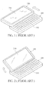
- a conventional sliding-type mobile phone includes an input module 100 and a display module 200 reciprocally movable with respect to each other (as the arrows indicate in FIG. 1 ), wherein the input module 100 includes a keypad 110, and the display module 200 includes a screen 210.
- the input module 100 and the display module 200 are movably connected by a sliding mechanism with a torsion hinge.
- the torsion hinge can provides a spring force to rotate the display module 200 upwardly, as shown in FIG. 2 , so that the display module 200 is angled with respect to the input module 100 for convenient usage.
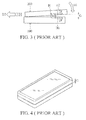
- the display module 200 When returning the display module 200 to a closed state, the display module 200 is pushed toward the input module 100, as the arrow D1 indicates in FIG. 3 , and the display module 200 is horizontally impelled along the upper surface of the input module 100, as the arrow D2 indicates in FIG. 3 . Hence, the display module 200 can be moved to a closed position, as shown in FIG. 4 .
- the torsion hinge H has a first plate H1 and a second plate H2 respectively connecting to the input module 100 and the display module 200.
- the torsion hinge H can provide a preloaded spring force F to rotate the display module 200 upwardly.
- the preloaded spring force F may adversely cause a gap G between the input module 100 and the display module 200 when in the closed state, as shown in FIGs. 3 and 4 .
- the gap G can cause disfigurement in unity of appearance of the mobile phone and cause mechanical failure of the torsion hinge H and the sliding mechanism following repeated operations.
- the application provides a moving mechanism including a torsion hinge, a slider, a lock member, and an elastic member disposed on the slider.
- the torsion hinge has a first plate and a second plate rotatable relative to each other.
- the lock member is rotatable relative to the first plate, and the slider is movably disposed on the second plate.
- the moving mechanism When the moving mechanism is in a closed state, the lock member is engaged with a slot portion of the second plate, so as to restrict the second plate in a predetermined angle.
- the elastic member pushes the lock member to release from the slot portion, such that the second plate is rotatable to an open position
- FIGs. 1-4 are perspective diagrams of a conventional sliding-type electronic device
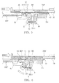
- FIG. 5 is a perspective diagram of a moving mechanism according to an embodiment of the invention.
- FIG. 6 is a perspective diagram of an elastic member pushing a lock member rotating according to an embodiment of the invention.
- FIG. 7 is a perspective diagram of a second plate of a torsion hinge rotating relative to a first plate of the torsion hinge according to an embodiment of the invention
- FIG. 8 is a perspective diagram of a slot portion of a second plate pushing a lock member rotating according to an embodiment of the invention.
- FIG. 9 is a perspective diagram of a hook of a lock member engaged with a slot portion of a second plate according to an embodiment of the invention.
- FIG. 10 is a perspective diagram of an elastic member which is slightly deformed when contacting a lock member according to an embodiment of the invention
- an embodiment of a moving mechanism is disposed in an electronic device to movably connect an input module 100' with a display module 200'. To simplify drawing complex objects, only parts of the input module 100' and the display module 200' are shown.
- the moving mechanism primarily includes a torsion hinge H, a fixed member 10, a slider 20, a lock member 30, and an elastic member 40.
- the torsion hinge H includes a first plate H1 mounted on the input module 100' and a second plate H2 automatically rotatable relative to the first plate H1.
- the fixed member 10 is fixed to the second plate H2, and the slider 20 is movably disposed on the fixed member 10, as the arrow indicates in FIG. 5 .
- the moving mechanism of the application is provided to connect the input module 100' and the display module 200', such that the display module 200' is slidable and rotatable relative to the input module 100' to adjust posture of the electronic device.
- the electronic device may be a mobile phone, PDA, pocket PC, Ultra-Mobile PC (UMPC), or tablet PC.
- the lock member 30 and the first plate H1 of FIG. 5 are pivotally connected via a hinge S. Additionally, the lock member 30 and the first plate H1 are connected via an elastic component R.
- the lock member 30 is in an initial position and contacts an end portion H11 of the first plate H1, wherein a hook 31 of the lock member 30 is engaged with a slot portion H21 of the second plate H2, thus restricting the second plate H2 at a predetermined angle.
- the second plate H2 is prohibited from upward rotation relative to the first plate H1, and the gap G as shown in FIGs. 3 and 4 can be suppressed.
- the slider 20 when a horizontal force is exerted on the display module 200', the slider 20 is moved rightward relative to the fixed member 10, so as to switch the electronic device from the closed state to an open state.
- the elastic member 40 pushes against a slope 32 of the lock member 30, so that the lock member 30 is rotated around the hinge S clockwise to separate the hook 31 from the slot portion H21.
- the hook 31 With the hook 31 separated from the slot portion H21, the second plate H2 and the fixed member 10 are automatically released from the predetermined angle and rotate upwardly to an open position relative to the first plate H1, as shown in FIG. 7 . Meanwhile, the hook 31 can automatically return to the initial position by elastic force of the elastic component R.
- the display module 200' is pushed to the left, and the slider 20 is moved leftward along the second plate H2.
- a contact surface 41 of the elastic member 40 contacts the lock member 30.
- the elastic member 40 is slightly deformed upwardly and slides across the upper surface of the lock member 30.
- the elastic member 40 is a metal sheet which has a spoon-shaped structure.
- the elastic component R may be a coil spring forcing the lock member 30 to contact the end portion H11 of the first plate H1 when in the initial position.
- the hinge S may be a torsion hinge which impels the hook 31 of the lock member 30 to engage with the slot portion H21 of the second plate H2.
- the elastic component R can be omitted from the moving mechanism when the hinge S is a torsion hinge.
- the application provides a moving mechanism movably connecting an input module 100' and a display module 200' of an electronic device.
- the second plate H2 is prohibited from rotation relative to the first plate H1 by a hook 31 of the lock member 30 engaging with a slot portion H21 of the second plate H2.
- the gap G shown in FIG. 4 can be suppressed.
- the application prevents disfigurement in unity of appearance and mechanical failure following repeated operations, thus extending usage life.
- a moving mechanism including a torsion hinge, a slider, a lock member, and an elastic member disposed on the slider.
- the torsion hinge has a first plate and a second plate rotatable relative to each other.
- the lock member is rotatable relative to the first plate, and the slider is movably disposed on the second plate.
- the moving mechanism When the moving mechanism is in a closed state, the lock member is engaged with a slot portion of the second plate, so as to restrict the second plate in a predetermined angle.
- the elastic member pushes the lock member to release from the slot portion, such that the second plate is rotatable to an open position.
Landscapes
- Engineering & Computer Science (AREA)
- Signal Processing (AREA)
- Telephone Set Structure (AREA)
Abstract
Description
- This Application claims priority of Taiwan Patent Application No.
098120979, filed on June 23, 2009 - This application relates in general to an electronic device and in particular to an electronic device including a moving mechanism.
- Referring to
FIG. 1 , a conventional sliding-type mobile phone includes aninput module 100 and adisplay module 200 reciprocally movable with respect to each other (as the arrows indicate inFIG. 1 ), wherein theinput module 100 includes akeypad 110, and thedisplay module 200 includes ascreen 210. - In the conventional sliding-type mobile phone, the
input module 100 and thedisplay module 200 are movably connected by a sliding mechanism with a torsion hinge. When thedisplay module 200 slides to a critical position relative to theinput module 100, the torsion hinge can provides a spring force to rotate thedisplay module 200 upwardly, as shown inFIG. 2 , so that thedisplay module 200 is angled with respect to theinput module 100 for convenient usage. - When returning the
display module 200 to a closed state, thedisplay module 200 is pushed toward theinput module 100, as the arrow D1 indicates inFIG. 3 , and thedisplay module 200 is horizontally impelled along the upper surface of theinput module 100, as the arrow D2 indicates inFIG. 3 . Hence, thedisplay module 200 can be moved to a closed position, as shown inFIG. 4 . - In
FIG. 3 , the torsion hinge H has a first plate H1 and a second plate H2 respectively connecting to theinput module 100 and thedisplay module 200. The torsion hinge H can provide a preloaded spring force F to rotate thedisplay module 200 upwardly. However, the preloaded spring force F may adversely cause a gap G between theinput module 100 and thedisplay module 200 when in the closed state, as shown inFIGs. 3 and 4 . The gap G can cause disfigurement in unity of appearance of the mobile phone and cause mechanical failure of the torsion hinge H and the sliding mechanism following repeated operations. - The application provides a moving mechanism including a torsion hinge, a slider, a lock member, and an elastic member disposed on the slider. The torsion hinge has a first plate and a second plate rotatable relative to each other. The lock member is rotatable relative to the first plate, and the slider is movably disposed on the second plate. When the moving mechanism is in a closed state, the lock member is engaged with a slot portion of the second plate, so as to restrict the second plate in a predetermined angle. When the slider slides relative to the second plate to a critical position, the elastic member pushes the lock member to release from the slot portion, such that the second plate is rotatable to an open position
- The invention can be more fully understood by reading the subsequent detailed description and examples with references made to the accompanying drawings, wherein:
-
FIGs. 1-4 are perspective diagrams of a conventional sliding-type electronic device; -
FIG. 5 is a perspective diagram of a moving mechanism according to an embodiment of the invention; -
FIG. 6 is a perspective diagram of an elastic member pushing a lock member rotating according to an embodiment of the invention; -
FIG. 7 is a perspective diagram of a second plate of a torsion hinge rotating relative to a first plate of the torsion hinge according to an embodiment of the invention; -
FIG. 8 is a perspective diagram of a slot portion of a second plate pushing a lock member rotating according to an embodiment of the invention; -
FIG. 9 is a perspective diagram of a hook of a lock member engaged with a slot portion of a second plate according to an embodiment of the invention; and -
FIG. 10 is a perspective diagram of an elastic member which is slightly deformed when contacting a lock member according to an embodiment of the invention - Referring to
FIG. 5 , an embodiment of a moving mechanism is disposed in an electronic device to movably connect an input module 100' with a display module 200'. To simplify drawing complex objects, only parts of the input module 100' and the display module 200' are shown. - In
FIG. 5 , the moving mechanism primarily includes a torsion hinge H, a fixedmember 10, aslider 20, alock member 30, and anelastic member 40. The torsion hinge H includes a first plate H1 mounted on the input module 100' and a second plate H2 automatically rotatable relative to the first plate H1. Furthermore, the fixedmember 10 is fixed to the second plate H2, and theslider 20 is movably disposed on the fixedmember 10, as the arrow indicates inFIG. 5 . - As described above, the moving mechanism of the application is provided to connect the input module 100' and the display module 200', such that the display module 200' is slidable and rotatable relative to the input module 100' to adjust posture of the electronic device. In some embodiments, the electronic device may be a mobile phone, PDA, pocket PC, Ultra-Mobile PC (UMPC), or tablet PC.
- The
lock member 30 and the first plate H1 ofFIG. 5 are pivotally connected via a hinge S. Additionally, thelock member 30 and the first plate H1 are connected via an elastic component R. When the input module 100' and the display module 200' are situated in a closed state, thelock member 30 is in an initial position and contacts an end portion H11 of the first plate H1, wherein ahook 31 of thelock member 30 is engaged with a slot portion H21 of the second plate H2, thus restricting the second plate H2 at a predetermined angle. Hence, the second plate H2 is prohibited from upward rotation relative to the first plate H1, and the gap G as shown inFIGs. 3 and 4 can be suppressed. - Referring to
FIG. 6 , when a horizontal force is exerted on the display module 200', theslider 20 is moved rightward relative to thefixed member 10, so as to switch the electronic device from the closed state to an open state. When theslider 20 moves relative to the fixedmember 10 to a critical position, as shown inFIG. 6 , theelastic member 40 pushes against aslope 32 of thelock member 30, so that thelock member 30 is rotated around the hinge S clockwise to separate thehook 31 from the slot portion H21. - With the
hook 31 separated from the slot portion H21, the second plate H2 and thefixed member 10 are automatically released from the predetermined angle and rotate upwardly to an open position relative to the first plate H1, as shown inFIG. 7 . Meanwhile, thehook 31 can automatically return to the initial position by elastic force of the elastic component R. - Referring
FIG. 8 , when returning the electronic device to the closed state, an external force is exerted on the display module 200' toward the input module 100'. Hence, theslider 20, thefixed member 10, and the second plate H2 are rotated toward the input module 100', as the arrow indicates inFIG. 8 . During downward rotation of the second plate H2, the slot portion H21 contacts theslope 32 of thelock member 30 and forces thelock member 30 rotating clockwise around the hinge S. While the second plate H2 returns to the predetermined angle, thelock member 30 rotates to the initial position by elastic force of the elastic component R, as shown inFIG. 9 . Hence, thehook 31 is engaged with the slot portion H21 again, to restrict the second plate H21 in the predetermined angle. - Referring to
FIG. 10 , after the second plate h2 returns to the predetermined angle, the display module 200' is pushed to the left, and theslider 20 is moved leftward along the second plate H2. During leftward motion of theslider 20, acontact surface 41 of theelastic member 40 contacts thelock member 30. As shown inFIG. 10 , theelastic member 40 is slightly deformed upwardly and slides across the upper surface of thelock member 30. With the display module 200' and theslider 20 moved to the left, the electronic device is returned to the closed state. - In this embodiment, the
elastic member 40 is a metal sheet which has a spoon-shaped structure. Additionally, the elastic component R may be a coil spring forcing thelock member 30 to contact the end portion H11 of the first plate H1 when in the initial position. In some embodiments, the hinge S may be a torsion hinge which impels thehook 31 of thelock member 30 to engage with the slot portion H21 of the second plate H2. In some embodiments, the elastic component R can be omitted from the moving mechanism when the hinge S is a torsion hinge. - The application provides a moving mechanism movably connecting an input module 100' and a display module 200' of an electronic device. The second plate H2 is prohibited from rotation relative to the first plate H1 by a
hook 31 of thelock member 30 engaging with a slot portion H21 of the second plate H2. Hence, the gap G shown inFIG. 4 can be suppressed. Additionally, the application prevents disfigurement in unity of appearance and mechanical failure following repeated operations, thus extending usage life.
In summary a moving mechanism is provided, including a torsion hinge, a slider, a lock member, and an elastic member disposed on the slider. The torsion hinge has a first plate and a second plate rotatable relative to each other. The lock member is rotatable relative to the first plate, and the slider is movably disposed on the second plate. When the moving mechanism is in a closed state, the lock member is engaged with a slot portion of the second plate, so as to restrict the second plate in a predetermined angle. When the slider slides relative to the second plate to a critical position, the elastic member pushes the lock member to release from the slot portion, such that the second plate is rotatable to an open position. - While the invention has been described by way of example and in terms of preferred embodiment, it is to be understood that the invention is not limited thereto. To the contrary, it is intended to cover various modifications and similar arrangements (as would be apparent to those skilled in the art). Therefore, the scope of the appended claims should be accorded the broadest interpretation to encompass all such modifications and similar arrangements.
Claims (10)
- An electronic device, comprising:a display module;an input module;a moving mechanism, comprising:a torsion hinge, having a first plate disposed on the input module and a second plate rotatable relative to the first plate, wherein the second plate has a slot portion;a fixed member, mounted on the second plate;a slider, fixed to the display module and slidable relative to the fixed member;a lock member, rotatable relative to the first plate, wherein when the moving mechanism is in a closed state, the lock member is in an initial position and engaged with the slot portion of the second plate to restrict the second plate in a predetermined angle; andan elastic member disposed on the slider, wherein when the slider moves relative to the fixed member to a critical position, the elastic member pushes the lock member to release from the slot portion, such that the second plate is rotatable relative to the first plate to an open position.
- The moving mechanism as claimed in claim 1, wherein the lock member has a slope, and when the slider moves relative to the fixed member to the critical position, the elastic member pushes the lock member rotating relative to the first plate.
- The moving mechanism as claimed in claim 2, wherein when the second plate rotates relative to the first plate from the open position toward the first plate, the slot portion contacts the slope and pushes the joining portion rotating relative to the first plate.
- The moving mechanism as claimed in one of the claims 1 to 3, wherein the moving mechanism further comprises an elastic component connecting the lock member and the first plate.
- The moving mechanism as claimed in claim 4, wherein when the second plate rotates relative to the first plate to the open position, the elastic component exerts an elastic force on the lock member, such that the lock member returns to the initial position.
- The moving mechanism as claimed in claim 4, wherein the lock member abuts the first plate when in the initial position.
- The moving mechanism as claimed in claim 4, wherein the elastic component comprises a coil spring.
- The moving mechanism as claimed in one of the claims 1 to 7, wherein the lock member has a hook engaged with the slot portion when the moving mechanism is in a closed state.
- The moving mechanism as claimed in one of the claims 1 to 8, wherein the elastic member has a spoon-shaped structure.
- The moving mechanism as claimed in one of the claims 1 to 9, wherein the elastic member comprises metal.
Applications Claiming Priority (1)
| Application Number | Priority Date | Filing Date | Title |
|---|---|---|---|
| TW098120979A TWI437948B (en) | 2009-06-23 | 2009-06-23 | Electronic device and moving mechanism thereof |
Publications (2)
| Publication Number | Publication Date |
|---|---|
| EP2267986A1 true EP2267986A1 (en) | 2010-12-29 |
| EP2267986B1 EP2267986B1 (en) | 2015-02-11 |
Family
ID=41666614
Family Applications (1)
| Application Number | Title | Priority Date | Filing Date |
|---|---|---|---|
| EP09179447.9A Active EP2267986B1 (en) | 2009-06-23 | 2009-12-16 | Electronic device and moving mechanism thereof |
Country Status (3)
| Country | Link |
|---|---|
| US (1) | US8369076B2 (en) |
| EP (1) | EP2267986B1 (en) |
| TW (1) | TWI437948B (en) |
Families Citing this family (13)
| Publication number | Priority date | Publication date | Assignee | Title |
|---|---|---|---|---|
| TWI363143B (en) * | 2009-06-18 | 2012-05-01 | Htc Corp | Electronic device and moving mechanism thereof |
| KR101601981B1 (en) | 2010-02-05 | 2016-03-17 | 삼성전자주식회사 | Portable communication device and cradling apparatus thereof |
| CN102859977B (en) * | 2010-05-20 | 2015-03-25 | 日本电气株式会社 | Portable apparatus |
| CN102680342A (en) * | 2011-03-10 | 2012-09-19 | 鸿富锦精密工业(深圳)有限公司 | Test device |
| CN102799231B (en) * | 2011-05-26 | 2016-06-08 | 罗普特(厦门)科技集团有限公司 | The display module of adjustable angles of display |
| TWI429375B (en) * | 2011-11-18 | 2014-03-01 | Wistron Corp | Electronic device with guiding mechanism for guiding flexible printed circuit board |
| TWM434422U (en) * | 2012-03-13 | 2012-07-21 | Wistron Corp | Supporting device and electronic device having supporting device |
| US8995117B1 (en) * | 2012-07-13 | 2015-03-31 | Google Inc. | Notebook computer with improved balance |
| TWI502321B (en) * | 2013-03-05 | 2015-10-01 | Wistron Corp | Electronic device |
| US9383777B1 (en) | 2013-09-27 | 2016-07-05 | Google Inc. | Notebook computer with lid mounting for translational movement |
| US9372513B1 (en) | 2013-09-27 | 2016-06-21 | Google Inc. | Coupling element for hinged electronic device |
| US9823631B1 (en) | 2013-10-01 | 2017-11-21 | Google Llc | Notebook computer with motorized display positioning |
| TWM547690U (en) * | 2016-05-26 | 2017-08-21 | 仁寶電腦工業股份有限公司 | Pivot structure and electronic device having the same |
Citations (4)
| Publication number | Priority date | Publication date | Assignee | Title |
|---|---|---|---|---|
| US20080081505A1 (en) * | 2006-10-03 | 2008-04-03 | High Tech Computer (Htc) Corporation | Electronic devices with sliding and tilting mechanisms, and associated methods |
| US20080304217A1 (en) * | 2007-06-05 | 2008-12-11 | Asustek Computer Inc. | Portable electronic device |
| EP2012506A2 (en) * | 2007-07-04 | 2009-01-07 | P & Tel Inc. | Slide hinge module and slide type equipment utilizing the same |
| US20090009949A1 (en) * | 2007-07-04 | 2009-01-08 | Asustek Computer Inc. | Cover flip mechanism and electronic device using the same |
Family Cites Families (5)
| Publication number | Priority date | Publication date | Assignee | Title |
|---|---|---|---|---|
| TW200723874A (en) | 2005-12-02 | 2007-06-16 | Hon Hai Prec Ind Co Ltd | Hinge mechanism |
| KR100833241B1 (en) | 2006-04-28 | 2008-05-28 | 삼성전자주식회사 | Sliding-tilt unit and mobile appliance adopting the same |
| CN100489325C (en) | 2006-07-07 | 2009-05-20 | 鸿富锦精密工业(深圳)有限公司 | Hinge mechanism |
| TWI329252B (en) * | 2007-06-01 | 2010-08-21 | Asustek Comp Inc | Portable electronic device |
| CN101335772A (en) | 2007-06-29 | 2008-12-31 | 明基电通信息技术有限公司 | Cover lifting mechanism, cover lifting method and electronic apparatus applying the same |
-
2009
- 2009-06-23 TW TW098120979A patent/TWI437948B/en active
- 2009-12-15 US US12/638,447 patent/US8369076B2/en active Active
- 2009-12-16 EP EP09179447.9A patent/EP2267986B1/en active Active
Patent Citations (4)
| Publication number | Priority date | Publication date | Assignee | Title |
|---|---|---|---|---|
| US20080081505A1 (en) * | 2006-10-03 | 2008-04-03 | High Tech Computer (Htc) Corporation | Electronic devices with sliding and tilting mechanisms, and associated methods |
| US20080304217A1 (en) * | 2007-06-05 | 2008-12-11 | Asustek Computer Inc. | Portable electronic device |
| EP2012506A2 (en) * | 2007-07-04 | 2009-01-07 | P & Tel Inc. | Slide hinge module and slide type equipment utilizing the same |
| US20090009949A1 (en) * | 2007-07-04 | 2009-01-08 | Asustek Computer Inc. | Cover flip mechanism and electronic device using the same |
Also Published As
| Publication number | Publication date |
|---|---|
| US8369076B2 (en) | 2013-02-05 |
| TW201101978A (en) | 2011-01-01 |
| EP2267986B1 (en) | 2015-02-11 |
| US20100321866A1 (en) | 2010-12-23 |
| TWI437948B (en) | 2014-05-11 |
Similar Documents
| Publication | Publication Date | Title |
|---|---|---|
| US8369076B2 (en) | Electronic device and moving mechanism thereof | |
| US8307510B2 (en) | Electronic device and moving mechanism thereof | |
| US8315044B2 (en) | Slide and tilt mechanism for electronic device | |
| US9001500B2 (en) | Sliding mechanism and electronic device using same | |
| EP2285075B1 (en) | Electronic device | |
| JP2005210649A (en) | Sliding mechanism of mobile terminal | |
| EP2257032A1 (en) | Electronic device | |
| CN100527758C (en) | Swing hinge device for mobile terminal | |
| US8289705B2 (en) | Electronic device | |
| EP2482528B1 (en) | Cradling apparatus for portable communication device | |
| US8462492B2 (en) | Sliding module for electronic device | |
| CN110460694A (en) | Electronic equipment | |
| EP2413576B1 (en) | Handheld electronic device | |
| US8433062B2 (en) | Tilting portable electronic device | |
| US20120293927A1 (en) | Sliding module for electronic device | |
| CN101938534B (en) | Electronic device and its moving mechanism | |
| US8625268B2 (en) | Sliding module for electronic device | |
| JP5169945B2 (en) | Information terminal equipment | |
| KR100899741B1 (en) | Sliding type portable terminal | |
| US8628244B2 (en) | Anti-interference structure of relative slide assembly | |
| KR101732736B1 (en) | Cradling apparatus for portable communication device | |
| KR20110078094A (en) | Sliding Handheld Terminal | |
| JP2010041304A (en) | Slide rotation hinge | |
| CN110460692A (en) | Electronic equipment | |
| KR20120136616A (en) | Personal portable device capable of multiple opening and closing |
Legal Events
| Date | Code | Title | Description |
|---|---|---|---|
| PUAI | Public reference made under article 153(3) epc to a published international application that has entered the european phase |
Free format text: ORIGINAL CODE: 0009012 |
|
| 17P | Request for examination filed |
Effective date: 20100521 |
|
| AK | Designated contracting states |
Kind code of ref document: A1 Designated state(s): AT BE BG CH CY CZ DE DK EE ES FI FR GB GR HR HU IE IS IT LI LT LU LV MC MK MT NL NO PL PT RO SE SI SK SM TR |
|
| AX | Request for extension of the european patent |
Extension state: AL BA RS |
|
| 17Q | First examination report despatched |
Effective date: 20140117 |
|
| GRAP | Despatch of communication of intention to grant a patent |
Free format text: ORIGINAL CODE: EPIDOSNIGR1 |
|
| GRAS | Grant fee paid |
Free format text: ORIGINAL CODE: EPIDOSNIGR3 |
|
| INTG | Intention to grant announced |
Effective date: 20141023 |
|
| GRAA | (expected) grant |
Free format text: ORIGINAL CODE: 0009210 |
|
| AK | Designated contracting states |
Kind code of ref document: B1 Designated state(s): AT BE BG CH CY CZ DE DK EE ES FI FR GB GR HR HU IE IS IT LI LT LU LV MC MK MT NL NO PL PT RO SE SI SK SM TR |
|
| REG | Reference to a national code |
Ref country code: GB Ref legal event code: FG4D |
|
| REG | Reference to a national code |
Ref country code: CH Ref legal event code: EP |
|
| REG | Reference to a national code |
Ref country code: CH Ref legal event code: PCOW Free format text: NEW ADDRESS: NO. 23, XINGHUA ROAD TAOYUAN DISTRICT, TAOYUAN CITY 330 (TW) |
|
| REG | Reference to a national code |
Ref country code: IE Ref legal event code: FG4D |
|
| REG | Reference to a national code |
Ref country code: AT Ref legal event code: REF Ref document number: 710228 Country of ref document: AT Kind code of ref document: T Effective date: 20150315 |
|
| RAP2 | Party data changed (patent owner data changed or rights of a patent transferred) |
Owner name: HTC CORPORATION |
|
| REG | Reference to a national code |
Ref country code: DE Ref legal event code: R096 Ref document number: 602009029326 Country of ref document: DE Effective date: 20150326 |
|
| REG | Reference to a national code |
Ref country code: NL Ref legal event code: T3 |
|
| REG | Reference to a national code |
Ref country code: AT Ref legal event code: MK05 Ref document number: 710228 Country of ref document: AT Kind code of ref document: T Effective date: 20150211 |
|
| REG | Reference to a national code |
Ref country code: LT Ref legal event code: MG4D |
|
| PG25 | Lapsed in a contracting state [announced via postgrant information from national office to epo] |
Ref country code: NO Free format text: LAPSE BECAUSE OF FAILURE TO SUBMIT A TRANSLATION OF THE DESCRIPTION OR TO PAY THE FEE WITHIN THE PRESCRIBED TIME-LIMIT Effective date: 20150511 Ref country code: ES Free format text: LAPSE BECAUSE OF FAILURE TO SUBMIT A TRANSLATION OF THE DESCRIPTION OR TO PAY THE FEE WITHIN THE PRESCRIBED TIME-LIMIT Effective date: 20150211 Ref country code: LT Free format text: LAPSE BECAUSE OF FAILURE TO SUBMIT A TRANSLATION OF THE DESCRIPTION OR TO PAY THE FEE WITHIN THE PRESCRIBED TIME-LIMIT Effective date: 20150211 Ref country code: HR Free format text: LAPSE BECAUSE OF FAILURE TO SUBMIT A TRANSLATION OF THE DESCRIPTION OR TO PAY THE FEE WITHIN THE PRESCRIBED TIME-LIMIT Effective date: 20150211 Ref country code: FI Free format text: LAPSE BECAUSE OF FAILURE TO SUBMIT A TRANSLATION OF THE DESCRIPTION OR TO PAY THE FEE WITHIN THE PRESCRIBED TIME-LIMIT Effective date: 20150211 Ref country code: SE Free format text: LAPSE BECAUSE OF FAILURE TO SUBMIT A TRANSLATION OF THE DESCRIPTION OR TO PAY THE FEE WITHIN THE PRESCRIBED TIME-LIMIT Effective date: 20150211 |
|
| PG25 | Lapsed in a contracting state [announced via postgrant information from national office to epo] |
Ref country code: GR Free format text: LAPSE BECAUSE OF FAILURE TO SUBMIT A TRANSLATION OF THE DESCRIPTION OR TO PAY THE FEE WITHIN THE PRESCRIBED TIME-LIMIT Effective date: 20150512 Ref country code: AT Free format text: LAPSE BECAUSE OF FAILURE TO SUBMIT A TRANSLATION OF THE DESCRIPTION OR TO PAY THE FEE WITHIN THE PRESCRIBED TIME-LIMIT Effective date: 20150211 Ref country code: LV Free format text: LAPSE BECAUSE OF FAILURE TO SUBMIT A TRANSLATION OF THE DESCRIPTION OR TO PAY THE FEE WITHIN THE PRESCRIBED TIME-LIMIT Effective date: 20150211 Ref country code: IS Free format text: LAPSE BECAUSE OF FAILURE TO SUBMIT A TRANSLATION OF THE DESCRIPTION OR TO PAY THE FEE WITHIN THE PRESCRIBED TIME-LIMIT Effective date: 20150611 |
|
| PG25 | Lapsed in a contracting state [announced via postgrant information from national office to epo] |
Ref country code: SK Free format text: LAPSE BECAUSE OF FAILURE TO SUBMIT A TRANSLATION OF THE DESCRIPTION OR TO PAY THE FEE WITHIN THE PRESCRIBED TIME-LIMIT Effective date: 20150211 Ref country code: RO Free format text: LAPSE BECAUSE OF FAILURE TO SUBMIT A TRANSLATION OF THE DESCRIPTION OR TO PAY THE FEE WITHIN THE PRESCRIBED TIME-LIMIT Effective date: 20150211 Ref country code: DK Free format text: LAPSE BECAUSE OF FAILURE TO SUBMIT A TRANSLATION OF THE DESCRIPTION OR TO PAY THE FEE WITHIN THE PRESCRIBED TIME-LIMIT Effective date: 20150211 Ref country code: CZ Free format text: LAPSE BECAUSE OF FAILURE TO SUBMIT A TRANSLATION OF THE DESCRIPTION OR TO PAY THE FEE WITHIN THE PRESCRIBED TIME-LIMIT Effective date: 20150211 Ref country code: EE Free format text: LAPSE BECAUSE OF FAILURE TO SUBMIT A TRANSLATION OF THE DESCRIPTION OR TO PAY THE FEE WITHIN THE PRESCRIBED TIME-LIMIT Effective date: 20150211 |
|
| REG | Reference to a national code |
Ref country code: DE Ref legal event code: R097 Ref document number: 602009029326 Country of ref document: DE |
|
| PG25 | Lapsed in a contracting state [announced via postgrant information from national office to epo] |
Ref country code: PL Free format text: LAPSE BECAUSE OF FAILURE TO SUBMIT A TRANSLATION OF THE DESCRIPTION OR TO PAY THE FEE WITHIN THE PRESCRIBED TIME-LIMIT Effective date: 20150211 |
|
| REG | Reference to a national code |
Ref country code: FR Ref legal event code: PLFP Year of fee payment: 7 |
|
| PLBE | No opposition filed within time limit |
Free format text: ORIGINAL CODE: 0009261 |
|
| STAA | Information on the status of an ep patent application or granted ep patent |
Free format text: STATUS: NO OPPOSITION FILED WITHIN TIME LIMIT |
|
| PG25 | Lapsed in a contracting state [announced via postgrant information from national office to epo] |
Ref country code: IT Free format text: LAPSE BECAUSE OF FAILURE TO SUBMIT A TRANSLATION OF THE DESCRIPTION OR TO PAY THE FEE WITHIN THE PRESCRIBED TIME-LIMIT Effective date: 20150211 |
|
| 26N | No opposition filed |
Effective date: 20151112 |
|
| PG25 | Lapsed in a contracting state [announced via postgrant information from national office to epo] |
Ref country code: SI Free format text: LAPSE BECAUSE OF FAILURE TO SUBMIT A TRANSLATION OF THE DESCRIPTION OR TO PAY THE FEE WITHIN THE PRESCRIBED TIME-LIMIT Effective date: 20150211 |
|
| PG25 | Lapsed in a contracting state [announced via postgrant information from national office to epo] |
Ref country code: BE Free format text: LAPSE BECAUSE OF FAILURE TO SUBMIT A TRANSLATION OF THE DESCRIPTION OR TO PAY THE FEE WITHIN THE PRESCRIBED TIME-LIMIT Effective date: 20150211 |
|
| PG25 | Lapsed in a contracting state [announced via postgrant information from national office to epo] |
Ref country code: LU Free format text: LAPSE BECAUSE OF FAILURE TO SUBMIT A TRANSLATION OF THE DESCRIPTION OR TO PAY THE FEE WITHIN THE PRESCRIBED TIME-LIMIT Effective date: 20151216 Ref country code: MC Free format text: LAPSE BECAUSE OF FAILURE TO SUBMIT A TRANSLATION OF THE DESCRIPTION OR TO PAY THE FEE WITHIN THE PRESCRIBED TIME-LIMIT Effective date: 20150211 |
|
| REG | Reference to a national code |
Ref country code: CH Ref legal event code: PL |
|
| REG | Reference to a national code |
Ref country code: IE Ref legal event code: MM4A |
|
| PG25 | Lapsed in a contracting state [announced via postgrant information from national office to epo] |
Ref country code: CH Free format text: LAPSE BECAUSE OF NON-PAYMENT OF DUE FEES Effective date: 20151231 Ref country code: LI Free format text: LAPSE BECAUSE OF NON-PAYMENT OF DUE FEES Effective date: 20151231 Ref country code: IE Free format text: LAPSE BECAUSE OF NON-PAYMENT OF DUE FEES Effective date: 20151216 |
|
| REG | Reference to a national code |
Ref country code: FR Ref legal event code: PLFP Year of fee payment: 8 |
|
| PG25 | Lapsed in a contracting state [announced via postgrant information from national office to epo] |
Ref country code: HU Free format text: LAPSE BECAUSE OF FAILURE TO SUBMIT A TRANSLATION OF THE DESCRIPTION OR TO PAY THE FEE WITHIN THE PRESCRIBED TIME-LIMIT; INVALID AB INITIO Effective date: 20091216 Ref country code: BG Free format text: LAPSE BECAUSE OF FAILURE TO SUBMIT A TRANSLATION OF THE DESCRIPTION OR TO PAY THE FEE WITHIN THE PRESCRIBED TIME-LIMIT Effective date: 20150211 Ref country code: SM Free format text: LAPSE BECAUSE OF FAILURE TO SUBMIT A TRANSLATION OF THE DESCRIPTION OR TO PAY THE FEE WITHIN THE PRESCRIBED TIME-LIMIT Effective date: 20150211 |
|
| PG25 | Lapsed in a contracting state [announced via postgrant information from national office to epo] |
Ref country code: CY Free format text: LAPSE BECAUSE OF FAILURE TO SUBMIT A TRANSLATION OF THE DESCRIPTION OR TO PAY THE FEE WITHIN THE PRESCRIBED TIME-LIMIT Effective date: 20150211 |
|
| PG25 | Lapsed in a contracting state [announced via postgrant information from national office to epo] |
Ref country code: MT Free format text: LAPSE BECAUSE OF FAILURE TO SUBMIT A TRANSLATION OF THE DESCRIPTION OR TO PAY THE FEE WITHIN THE PRESCRIBED TIME-LIMIT Effective date: 20150211 Ref country code: TR Free format text: LAPSE BECAUSE OF FAILURE TO SUBMIT A TRANSLATION OF THE DESCRIPTION OR TO PAY THE FEE WITHIN THE PRESCRIBED TIME-LIMIT Effective date: 20150211 |
|
| REG | Reference to a national code |
Ref country code: FR Ref legal event code: PLFP Year of fee payment: 9 |
|
| PG25 | Lapsed in a contracting state [announced via postgrant information from national office to epo] |
Ref country code: PT Free format text: LAPSE BECAUSE OF FAILURE TO SUBMIT A TRANSLATION OF THE DESCRIPTION OR TO PAY THE FEE WITHIN THE PRESCRIBED TIME-LIMIT Effective date: 20150211 Ref country code: MK Free format text: LAPSE BECAUSE OF FAILURE TO SUBMIT A TRANSLATION OF THE DESCRIPTION OR TO PAY THE FEE WITHIN THE PRESCRIBED TIME-LIMIT Effective date: 20150211 |
|
| P01 | Opt-out of the competence of the unified patent court (upc) registered |
Effective date: 20230602 |
|
| PGFP | Annual fee paid to national office [announced via postgrant information from national office to epo] |
Ref country code: NL Payment date: 20241004 Year of fee payment: 16 |
|
| PGFP | Annual fee paid to national office [announced via postgrant information from national office to epo] |
Ref country code: DE Payment date: 20241023 Year of fee payment: 16 |
|
| PGFP | Annual fee paid to national office [announced via postgrant information from national office to epo] |
Ref country code: GB Payment date: 20241001 Year of fee payment: 16 |
|
| PGFP | Annual fee paid to national office [announced via postgrant information from national office to epo] |
Ref country code: FR Payment date: 20241008 Year of fee payment: 16 |