EP2267839A2 - Radome and shroud enclosure for reflector antenna - Google Patents
Radome and shroud enclosure for reflector antenna Download PDFInfo
- Publication number
- EP2267839A2 EP2267839A2 EP10005417A EP10005417A EP2267839A2 EP 2267839 A2 EP2267839 A2 EP 2267839A2 EP 10005417 A EP10005417 A EP 10005417A EP 10005417 A EP10005417 A EP 10005417A EP 2267839 A2 EP2267839 A2 EP 2267839A2
- Authority
- EP
- European Patent Office
- Prior art keywords
- shroud
- enclosure
- retaining
- radome
- reflector antenna
- Prior art date
- Legal status (The legal status is an assumption and is not a legal conclusion. Google has not performed a legal analysis and makes no representation as to the accuracy of the status listed.)
- Granted
Links
Images







Classifications
-
- H—ELECTRICITY
- H01—ELECTRIC ELEMENTS
- H01Q—ANTENNAS, i.e. RADIO AERIALS
- H01Q1/00—Details of, or arrangements associated with, antennas
- H01Q1/42—Housings not intimately mechanically associated with radiating elements, e.g. radome
-
- H—ELECTRICITY
- H01—ELECTRIC ELEMENTS
- H01Q—ANTENNAS, i.e. RADIO AERIALS
- H01Q17/00—Devices for absorbing waves radiated from an antenna; Combinations of such devices with active antenna elements or systems
-
- H—ELECTRICITY
- H01—ELECTRIC ELEMENTS
- H01Q—ANTENNAS, i.e. RADIO AERIALS
- H01Q19/00—Combinations of primary active antenna elements and units with secondary devices, e.g. with quasi-optical devices, for giving the antenna a desired directional characteristic
- H01Q19/10—Combinations of primary active antenna elements and units with secondary devices, e.g. with quasi-optical devices, for giving the antenna a desired directional characteristic using reflecting surfaces
- H01Q19/12—Combinations of primary active antenna elements and units with secondary devices, e.g. with quasi-optical devices, for giving the antenna a desired directional characteristic using reflecting surfaces wherein the surfaces are concave
- H01Q19/13—Combinations of primary active antenna elements and units with secondary devices, e.g. with quasi-optical devices, for giving the antenna a desired directional characteristic using reflecting surfaces wherein the surfaces are concave the primary radiating source being a single radiating element, e.g. a dipole, a slot, a waveguide termination
- H01Q19/134—Rear-feeds; Splash plate feeds
-
- Y—GENERAL TAGGING OF NEW TECHNOLOGICAL DEVELOPMENTS; GENERAL TAGGING OF CROSS-SECTIONAL TECHNOLOGIES SPANNING OVER SEVERAL SECTIONS OF THE IPC; TECHNICAL SUBJECTS COVERED BY FORMER USPC CROSS-REFERENCE ART COLLECTIONS [XRACs] AND DIGESTS
- Y10—TECHNICAL SUBJECTS COVERED BY FORMER USPC
- Y10T—TECHNICAL SUBJECTS COVERED BY FORMER US CLASSIFICATION
- Y10T29/00—Metal working
- Y10T29/49—Method of mechanical manufacture
- Y10T29/49002—Electrical device making
- Y10T29/49016—Antenna or wave energy "plumbing" making
Definitions
- This invention relates to microwave reflector antennas. More particularly, the invention relates to a radome and shroud enclosure for reflector antennas with improved signal pattern and mechanical characteristics.
- the open end of a reflector antenna is typically enclosed by a radome coupled to the distal end of the reflector dish and/or of a cylindrical shroud extending from the reflector dish.
- the radome provides environmental protection and improves wind load characteristics of the antenna. Precision shaping may be applied to the radome to compensate for signal trajectory and/or reflection effects resulting from an impedance discontinuity introduced into the signal path of the reflector antenna by the presence of the radome. Edge(s) of the radome attachment arrangement scatter the RF signal degrading the signal pattern. Significantly, edges parallel to the signal path, such as the distal edge of a cylindrical shroud, are known to diffract signal energy present in this area, introducing undesirable backlobes into the reflector antenna signal pattern.
- Prior antenna signal pattern backlobe suppression techniques include adding a backlobe suppression ring to the radome, for example via metalizing of the radome periphery as disclosed in commonly owned US Utility Patent No. 7,138,958 , titled "Reflector Antenna Radome with Backlobe Suppressor Ring and Method of Manufacturing” issued November 21, 2006 to Syed et al, hereby incorporated by reference in its entirety.
- the required metalizing operations may increase manufacturing complexity and/or cost, including elaborate coupling arrangements configured to securely retain the shroud upon the reflector dish without presenting undesired reflection edges and/or extending the overall size of the radome.
- the thin metalized ring layer applied to the periphery of the radome may be fragile, requiring increased care to avoid damage during delivery and/or installation.
- a shroud to a reflector antenna improves the signal pattern generally as a function of the shroud length, but also similarly introduces significant costs as the increasing length of the shroud also increases wind loading of the reflector antenna, requiring a corresponding increase in the antenna and antenna support structure strength.
- a first exemplary embodiment of a reflector antenna enclosure 1 is demonstrated in Figures 1-11 .
- a cylindrical shroud 3 extends, generally coaxial with a longitudinal axis of the reflector antenna 5, from a distal end 7 of the reflector dish 9.
- a proximal end 11 of the shroud 3 is coupled, for example via mechanical fastener(s) 13 or the like, to the periphery of the reflector dish 9.
- a retaining band 15 may be coupled to an inner diameter of the shroud 3, proximate the distal end 7 of the shroud 3.
- a radome 17 enclosing the distal end 7 of the shroud 3 cavity is seated within a retaining groove 19 of the retaining band 15.
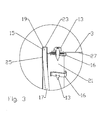
- the retaining band 15 has a cross section best demonstrated in Figure 3 .
- a mounting portion 21 of the retaining band 15 is coaxial with the shroud 3, dimensioned to seat against the inner diameter of the distal end 7 of the shroud 3, fastened for example by a plurality of fastener(s) 13 each threaded into a respective clip 16 placed upon the mounting portion 21.
- the retaining groove 19 extends outward from the mounting portion 21, open towards the longitudinal axis of the reflector antenna 5.
- a bottom 23 of the retaining groove 19 has an inner diameter that is greater than an outer diameter of the shroud 3.
- a width of the retaining groove 19 may generally correspond to a width of the radome periphery, enabling the radome periphery to seat within the retaining groove 19 and be retained thereby.
- the retaining groove 19 may be provided with a depth with respect to the mounting portion 21 that is greater than the width of the retaining groove 19. That is, the retaining groove bottom 23 may be provided with an inner diameter that is greater than the inner diameter of the mounting portion 21 by greater than the width of the retaining groove 19. Further, a radial inward edge 25 of the retaining band 15 may be provided with an inner diameter that is less than an inner diameter of the mounting portion 21. Thereby, the longitudinal length of the shroud 3 may reduced without unacceptably degrading the front-to-back ratio / back lobe signal pattern of the resulting reflector antenna 5.
- an RF absorbing material 29 may be applied to the inner diameter of the shroud 3, further reducing RF signal reflections therealong. If the shroud 3 is formed from polymer material, at least portions of the shroud 3 that are not covered by RF absorbing material 29 may be metalized to provide an RF signal block.
- the retaining band 15 may also provide a reinforcing function for the shroud 3, enabling the shroud 3 to be cost effectively formed, for example, from multiple portion(s) 27 of sheet metal and/or polymer material.
- the portions may be assembled at the point of installation by coupling them end to end via fasteners or the like to form the shroud cylinder.
- the RF absorbing material 29 may be mechanically fastened to the shroud inner diameter, enabling compact storage and delivery configurations with limited risk of damaging the relatively fragile RF absorbing material.
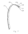
- the retaining band 15 may be formed as a C-ring or alternatively as best shown for example in Figure 7 as a plurality of retaining band 15 arc segment(s) 31 that are fastened together to form the annular shape of the retaining band 15.
- the arc segment(s) 31 may be formed with an end flare 35 wherein an end portion of each arc segment 31 can seat within and overlap one another.
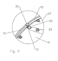
- the end portion(s) of each arc segment 31 may be provided with a coupling tab 33 through which a fastener 13 may be applied to couple the arc segment(s) 31 to one another, as best shown in Figures 8-11 .
- the dimensions determining the fit between the radome periphery and the retaining groove 19 may be selected to be an interference fit, immobilizing the radome 17 with respect to the retaining band 15 and improving the integrity of the shroud 3 and radome 17, for example with respect to resisting deformation under high sustained and/or gusting wind loads.
- dimensions resulting in a looser fit may be selected allowing the radome 17 to float and/or rotate within the retaining groove 19.
- a looser fit enables, for example, compensation for different thermal expansion characteristics of the selected radome 17 and retaining band 15 materials.
- the retaining groove 19 provides a circumferential retention of the radome 17 dependent upon the strength of the, for example metal, retaining band 15, the radome 17 retention is very secure, even if a relatively low strength material and/or thickness is selected for the radome 17. Further, the prior attachment features formed in the radome periphery have been eliminated, greatly simplifying radome 17 and also shroud distal end manufacture.
- the reflector antenna enclosure 1 enables significant manufacturing, delivery, installation and/or maintenance efficiencies.
Landscapes
- Aerials With Secondary Devices (AREA)
- Details Of Aerials (AREA)
Abstract
Description
- This application claims the benefit of
US Utility Patent Application No.: 12/484,123 - This invention relates to microwave reflector antennas. More particularly, the invention relates to a radome and shroud enclosure for reflector antennas with improved signal pattern and mechanical characteristics.
- The open end of a reflector antenna is typically enclosed by a radome coupled to the distal end of the reflector dish and/or of a cylindrical shroud extending from the reflector dish.
- The radome provides environmental protection and improves wind load characteristics of the antenna. Precision shaping may be applied to the radome to compensate for signal trajectory and/or reflection effects resulting from an impedance discontinuity introduced into the signal path of the reflector antenna by the presence of the radome. Edge(s) of the radome attachment arrangement scatter the RF signal degrading the signal pattern. Significantly, edges parallel to the signal path, such as the distal edge of a cylindrical shroud, are known to diffract signal energy present in this area, introducing undesirable backlobes into the reflector antenna signal pattern.
- Prior antenna signal pattern backlobe suppression techniques include adding a backlobe suppression ring to the radome, for example via metalizing of the radome periphery as disclosed in commonly owned
US Utility Patent No. 7,138,958 , titled "Reflector Antenna Radome with Backlobe Suppressor Ring and Method of Manufacturing" issued November 21, 2006 to Syed et al, hereby incorporated by reference in its entirety. However, the required metalizing operations may increase manufacturing complexity and/or cost, including elaborate coupling arrangements configured to securely retain the shroud upon the reflector dish without presenting undesired reflection edges and/or extending the overall size of the radome. Further, the thin metalized ring layer applied to the periphery of the radome may be fragile, requiring increased care to avoid damage during delivery and/or installation. - The addition of a shroud to a reflector antenna improves the signal pattern generally as a function of the shroud length, but also similarly introduces significant costs as the increasing length of the shroud also increases wind loading of the reflector antenna, requiring a corresponding increase in the antenna and antenna support structure strength.
- Competition in the reflector antenna market has focused attention on improving electrical performance and minimization of overall manufacturing, inventory, distribution, installation and maintenance costs. Therefore, it is an object of the invention to provide a radome and shroud enclosure for a reflector antenna that overcomes deficiencies in the prior art.
- The accompanying drawings, which are incorporated in and constitute a part of this specification, illustrate embodiments of the invention, where like reference numbers in the drawing figures refer to the same feature or element and may not be described in detail for every drawing figure in which they appear and, together with a general description of the invention given above, and the detailed description of the embodiments given below, serve to explain the principles of the invention.
-
Figure 1 is a schematic isometric front view of a reflector antenna with an exemplary shroud and radome enclosure. -
Figure 2 is a schematic cut-away side view of the reflector antenna ofFigure 1 , wherein RF absorbing material is omitted for clarity. -
Figure 3 is a close-up view of area A ofFigure 2 . -
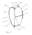
Figure 4 an isometric cut-away side view of the reflector antenna ofFigure 1 . -
Figure 5 is a close-up view of area B ofFigure 4 . -
Figure 6 is a close-up view of area C ofFigure 4 . -
Figure 7 is a schematic isometric front view of a retaining band arc segment ofFigure 1 . -
Figure 8 is a schematic isometric back view of the reflector antenna ofFigure 1 . -
Figure 9 is a close-up view of area D ofFigure 8 . -
Figure 10 is an isometric cut-away side view of the reflector antenna ofFigure 1 . -
Figure 11 is a close-up view of area E ofFigure 10 . - A first exemplary embodiment of a
reflector antenna enclosure 1 is demonstrated inFigures 1-11 . Acylindrical shroud 3 extends, generally coaxial with a longitudinal axis of thereflector antenna 5, from adistal end 7 of the reflector dish 9. Aproximal end 11 of theshroud 3 is coupled, for example via mechanical fastener(s) 13 or the like, to the periphery of the reflector dish 9. Aretaining band 15 may be coupled to an inner diameter of theshroud 3, proximate thedistal end 7 of theshroud 3. Aradome 17 enclosing thedistal end 7 of theshroud 3 cavity is seated within aretaining groove 19 of theretaining band 15. - The
retaining band 15 has a cross section best demonstrated inFigure 3 . Amounting portion 21 of theretaining band 15 is coaxial with theshroud 3, dimensioned to seat against the inner diameter of thedistal end 7 of theshroud 3, fastened for example by a plurality of fastener(s) 13 each threaded into arespective clip 16 placed upon themounting portion 21. Theretaining groove 19 extends outward from themounting portion 21, open towards the longitudinal axis of thereflector antenna 5. Abottom 23 of theretaining groove 19 has an inner diameter that is greater than an outer diameter of theshroud 3. A width of theretaining groove 19 may generally correspond to a width of the radome periphery, enabling the radome periphery to seat within theretaining groove 19 and be retained thereby. - To provide an improved choke effect upon signal energy in the area of the
retaining groove 19, theretaining groove 19 may be provided with a depth with respect to themounting portion 21 that is greater than the width of theretaining groove 19. That is, theretaining groove bottom 23 may be provided with an inner diameter that is greater than the inner diameter of themounting portion 21 by greater than the width of theretaining groove 19. Further, a radialinward edge 25 of theretaining band 15 may be provided with an inner diameter that is less than an inner diameter of themounting portion 21. Thereby, the longitudinal length of theshroud 3 may reduced without unacceptably degrading the front-to-back ratio / back lobe signal pattern of the resultingreflector antenna 5. - As shown in
Figures 4-6 ,10 and11 , anRF absorbing material 29 may be applied to the inner diameter of theshroud 3, further reducing RF signal reflections therealong. If theshroud 3 is formed from polymer material, at least portions of theshroud 3 that are not covered byRF absorbing material 29 may be metalized to provide an RF signal block. - The
retaining band 15 may also provide a reinforcing function for theshroud 3, enabling theshroud 3 to be cost effectively formed, for example, from multiple portion(s) 27 of sheet metal and/or polymer material. To simplify manufacturing, reduce inventory and delivery costs, the portions may be assembled at the point of installation by coupling them end to end via fasteners or the like to form the shroud cylinder. Similarly, theRF absorbing material 29 may be mechanically fastened to the shroud inner diameter, enabling compact storage and delivery configurations with limited risk of damaging the relatively fragile RF absorbing material. - The
retaining band 15 may be formed as a C-ring or alternatively as best shown for example inFigure 7 as a plurality ofretaining band 15 arc segment(s) 31 that are fastened together to form the annular shape of theretaining band 15. Where theretaining band 15 is formed from arc segment(s) 31, the arc segment(s) 31 may be formed with anend flare 35 wherein an end portion of eacharc segment 31 can seat within and overlap one another. In addition and/or alternatively, the end portion(s) of eacharc segment 31 may be provided with acoupling tab 33 through which afastener 13 may be applied to couple the arc segment(s) 31 to one another, as best shown inFigures 8-11 . - Because the
retaining groove 19 is isolated from theshroud 3, theradome 17 makes no contact with theshroud 3. Therefore, the characteristics of the fit between theretaining groove 15 and theradome 17 has no effect upon the interconnection between theshroud 3 and theretaining band 15. The dimensions determining the fit between the radome periphery and theretaining groove 19 may be selected to be an interference fit, immobilizing theradome 17 with respect to theretaining band 15 and improving the integrity of theshroud 3 andradome 17, for example with respect to resisting deformation under high sustained and/or gusting wind loads. Alternatively, dimensions resulting in a looser fit may be selected allowing theradome 17 to float and/or rotate within theretaining groove 19. A looser fit enables, for example, compensation for different thermal expansion characteristics of the selectedradome 17 and retainingband 15 materials. - Because the
retaining groove 19 provides a circumferential retention of theradome 17 dependent upon the strength of the, for example metal, retainingband 15, theradome 17 retention is very secure, even if a relatively low strength material and/or thickness is selected for theradome 17. Further, the prior attachment features formed in the radome periphery have been eliminated, greatly simplifyingradome 17 and also shroud distal end manufacture. - One skilled in the art will appreciate that in addition to improving the electrical performance of the
reflector antenna 5, thereflector antenna enclosure 1 enables significant manufacturing, delivery, installation and/or maintenance efficiencies.Table of Parts 1 reflector antenna enclosure 3 shroud 5 reflector antenna 7 distal end 9 reflector dish 11 proximal end 13 fastener 15 retaining band 16 clip 17 radome 19 retaining groove 21 mounting portion 23 bottom 25 edge 27 portion 29 RF absorbing material 31 arc segment 33 coupling tab 35 end flare - Where in the foregoing description reference has been made to materials, ratios, integers or components having known equivalents then such equivalents are herein incorporated as if individually set forth.
- While the present invention has been illustrated by the description of the embodiments thereof, and while the embodiments have been described in considerable detail, it is not the intention of the applicant to restrict or in any way limit the scope of the appended claims to such detail. Additional advantages and modifications will readily appear to those skilled in the art. Therefore, the invention in its broader aspects is not limited to the specific details, representative apparatus, methods, and illustrative examples shown and described. Accordingly, departures may be made from such details without departure from the spirit or scope of applicant's general inventive concept. Further, it is to be appreciated that improvements and/or modifications may be made thereto without departing from the scope or spirit of the present invention as defined by the following claims.
Claims (15)
- An enclosure for an open end of a reflector antenna, comprising:a substantially cylindrical shroud adapted to be coupled to a distal end of the reflector antenna, the shroud generally coaxial with a longitudinal axis of the reflector antenna;a retaining band coupled to an inner diameter of the shroud, proximate a distal end of the shroud;the retaining band provided with a retaining groove open radially inward towards the longitudinal axis;a bottom of the retaining groove extending radially outward beyond an outer diameter of the shroud; anda radome seated within the retaining groove.
- The enclosure of claim 1, wherein the retaining band is formed by a plurality of arc segments.
- The enclosure of claim 2, further including an end flare on each of the arc segments, whereby an end of each arc segment overlaps an adjacent arc segment.
- The enclosure of claim 2, further including a coupling tab proximate an end of each arc segment, the coupling tabs fastened one to another.
- The enclosure of claim 1, further including an RF absorbing material coupled to the inner diameter of the shroud.
- The enclosure of claim 5, wherein the RF absorbing material is mechanically fastened to the shroud.
- The enclosure of claim 1, wherein a diameter at the bottom of the retaining groove is greater than an outer diameter of the shroud by at least one width of the retaining groove.
- The enclosure of claim 1, wherein the retaining band is coupled to the shroud by fasteners coupled through an outer diameter of the shroud to clips seated on a proximal edge of the retaining band.
- The enclosure of claim 1, wherein the radome does not contact the shroud.
- The enclosure of claim 1, wherein the radome is rotatable within the retaining groove.
- The enclosure of claim 1, wherein the radome is movable within the retaining groove.
- The enclosure of claim 1, wherein a radial inward edge of the retaining band has a smaller inner diameter than the shroud.
- The enclosure of claim 1, wherein a radial inward edge of the retaining band has
a smaller inner diameter than a proximal end of the retaining band. - An enclosure for an open end of a reflector antenna, comprising:a substantially cylindrical shroud adapted to be coupled to a distal end of the reflector antenna, the shroud generally coaxial with a longitudinal axis of the reflector antenna;an RF absorbing material coupled to the inner diameter of the shroud;a retaining band coupled to an inner diameter of the shroud, proximate a distal end of the shroud; the retaining band formed by a plurality of interconnected arc segments;the retaining band provided with a retaining groove open radially inward towards the longitudinal axis;a diameter at the bottom of the retaining groove is greater than an outer diameter of the shroud by at least one width of the retaining groove;a bottom of the retaining groove extending radially outward beyond an outer diameter of the shroud;a radial inward edge of the retaining band has a smaller inner diameter than the shroud; anda radome seated within the retaining groove without contacting the shroud.
- Method for assembling an enclosure upon an open end of a reflector antenna, comprising the steps of:coupling a plurality of portions together to form a substantially cylindrical shroud;coupling the shroud to a distal end of the reflector antenna, the shroud generally coaxial with a longitudinal axis of the reflector antenna;coupling a plurality of arc segments together around a periphery of a radome to form a retaining band;the retaining band provided with a retaining groove open radially inward towards the longitudinal axis, the radome seated in the retaining groove; andcoupling a mounting portion to an inner diameter of a distal end of the cylindrical shroud.
Applications Claiming Priority (1)
| Application Number | Priority Date | Filing Date | Title |
|---|---|---|---|
| US12/484,123 US8077113B2 (en) | 2009-06-12 | 2009-06-12 | Radome and shroud enclosure for reflector antenna |
Publications (3)
| Publication Number | Publication Date |
|---|---|
| EP2267839A2 true EP2267839A2 (en) | 2010-12-29 |
| EP2267839A3 EP2267839A3 (en) | 2012-12-19 |
| EP2267839B1 EP2267839B1 (en) | 2019-10-02 |
Family
ID=42813382
Family Applications (1)
| Application Number | Title | Priority Date | Filing Date |
|---|---|---|---|
| EP10005417.0A Active EP2267839B1 (en) | 2009-06-12 | 2010-05-25 | Radome and shroud enclosure for reflector antenna |
Country Status (3)
| Country | Link |
|---|---|
| US (1) | US8077113B2 (en) |
| EP (1) | EP2267839B1 (en) |
| CN (1) | CN101924276B (en) |
Cited By (1)
| Publication number | Priority date | Publication date | Assignee | Title |
|---|---|---|---|---|
| EP2891211B1 (en) * | 2012-08-31 | 2022-02-16 | CommScope Technologies LLC | Radome attachment band clamp |
Families Citing this family (227)
| Publication number | Priority date | Publication date | Assignee | Title |
|---|---|---|---|---|
| US9634373B2 (en) * | 2009-06-04 | 2017-04-25 | Ubiquiti Networks, Inc. | Antenna isolation shrouds and reflectors |
| US8836601B2 (en) | 2013-02-04 | 2014-09-16 | Ubiquiti Networks, Inc. | Dual receiver/transmitter radio devices with choke |
| US9496620B2 (en) | 2013-02-04 | 2016-11-15 | Ubiquiti Networks, Inc. | Radio system for long-range high-speed wireless communication |
| US8581795B2 (en) | 2011-09-01 | 2013-11-12 | Andrew Llc | Low sidelobe reflector antenna |
| US9019164B2 (en) | 2011-09-12 | 2015-04-28 | Andrew Llc | Low sidelobe reflector antenna with shield |
| US9343798B2 (en) * | 2011-09-26 | 2016-05-17 | Gary Gwoon Wong | High performance (mini-cube) indoor HDTV antenna |
| US9050692B2 (en) * | 2011-10-24 | 2015-06-09 | Commscope Technologies Llc | Method and apparatus for radome and reflector dish interconnection |
| US8789116B2 (en) | 2011-11-18 | 2014-07-22 | Electronic Controlled Systems, Inc. | Satellite television antenna system |
| CN103367903A (en) * | 2012-03-31 | 2013-10-23 | 深圳光启创新技术有限公司 | Meta-material antenna housing and antenna system |
| US9093737B2 (en) * | 2012-05-04 | 2015-07-28 | Mark R. Bacon | Enclosure with self-contained adjustable shrouding |
| EP2712019B1 (en) * | 2012-09-24 | 2017-11-22 | Alcatel- Lucent Shanghai Bell Co., Ltd | Device for attaching a radome to a parabolic reflector of an antenna |
| US9113347B2 (en) | 2012-12-05 | 2015-08-18 | At&T Intellectual Property I, Lp | Backhaul link for distributed antenna system |
| US9543635B2 (en) | 2013-02-04 | 2017-01-10 | Ubiquiti Networks, Inc. | Operation of radio devices for long-range high-speed wireless communication |
| US20160218406A1 (en) | 2013-02-04 | 2016-07-28 | John R. Sanford | Coaxial rf dual-polarized waveguide filter and method |
| US9397820B2 (en) | 2013-02-04 | 2016-07-19 | Ubiquiti Networks, Inc. | Agile duplexing wireless radio devices |
| US9531067B2 (en) | 2013-02-08 | 2016-12-27 | Ubiquiti Networks, Inc. | Adjustable-tilt housing with flattened dome shape, array antenna, and bracket mount |
| US9930592B2 (en) | 2013-02-19 | 2018-03-27 | Mimosa Networks, Inc. | Systems and methods for directing mobile device connectivity |
| US9179336B2 (en) | 2013-02-19 | 2015-11-03 | Mimosa Networks, Inc. | WiFi management interface for microwave radio and reset to factory defaults |
| WO2014138292A1 (en) * | 2013-03-06 | 2014-09-12 | Mimosa Networks, Inc. | Enclosure for radio, parabolic dish antenna, and side lobe shields |
| US9130305B2 (en) | 2013-03-06 | 2015-09-08 | Mimosa Networks, Inc. | Waterproof apparatus for cables and cable interfaces |
| US10742275B2 (en) | 2013-03-07 | 2020-08-11 | Mimosa Networks, Inc. | Quad-sector antenna using circular polarization |
| US9191081B2 (en) | 2013-03-08 | 2015-11-17 | Mimosa Networks, Inc. | System and method for dual-band backhaul radio |
| US10530051B2 (en) | 2013-03-15 | 2020-01-07 | 3Z Telecom, Inc. | Antenna alignment device and methods for aligning antennas |
| US20140266925A1 (en) | 2013-03-15 | 2014-09-18 | Enzo Dalmazzo | Antenna Alignment Device and Clamp |
| US9295103B2 (en) | 2013-05-30 | 2016-03-22 | Mimosa Networks, Inc. | Wireless access points providing hybrid 802.11 and scheduled priority access communications |
| US9525524B2 (en) | 2013-05-31 | 2016-12-20 | At&T Intellectual Property I, L.P. | Remote distributed antenna system |
| US9999038B2 (en) | 2013-05-31 | 2018-06-12 | At&T Intellectual Property I, L.P. | Remote distributed antenna system |
| US10938110B2 (en) | 2013-06-28 | 2021-03-02 | Mimosa Networks, Inc. | Ellipticity reduction in circularly polarized array antennas |
| PL3055930T3 (en) | 2013-10-11 | 2020-05-18 | Ubiquiti Inc. | Wireless radio system optimization by persistent spectrum analysis |
| US9583822B2 (en) * | 2013-10-30 | 2017-02-28 | Commscope Technologies Llc | Broad band radome for microwave antenna |
| US9985347B2 (en) | 2013-10-30 | 2018-05-29 | Commscope Technologies Llc | Broad band radome for microwave antenna |
| US8897697B1 (en) | 2013-11-06 | 2014-11-25 | At&T Intellectual Property I, Lp | Millimeter-wave surface-wave communications |
| US9001689B1 (en) | 2014-01-24 | 2015-04-07 | Mimosa Networks, Inc. | Channel optimization in half duplex communications systems |
| US9780892B2 (en) | 2014-03-05 | 2017-10-03 | Mimosa Networks, Inc. | System and method for aligning a radio using an automated audio guide |
| LT3114884T (en) | 2014-03-07 | 2020-02-10 | Ubiquiti Inc. | IDENTIFICATION AND AUTHENTICATION OF THE CIRCULAR DEVICE |
| US20150256355A1 (en) | 2014-03-07 | 2015-09-10 | Robert J. Pera | Wall-mounted interactive sensing and audio-visual node devices for networked living and work spaces |
| US10574474B2 (en) | 2014-03-07 | 2020-02-25 | Ubiquiti Inc. | Integrated power receptacle wireless access point (AP) adapter devices |
| US9577323B2 (en) | 2014-03-07 | 2017-02-21 | Commscope Technologies Llc | Radome—reflector assembly mechanism |
| US9998246B2 (en) | 2014-03-13 | 2018-06-12 | Mimosa Networks, Inc. | Simultaneous transmission on shared channel |
| WO2015138000A1 (en) * | 2014-03-14 | 2015-09-17 | Dalmazzo Enzo | Antenna alignment device and clamp |
| US9912053B2 (en) | 2014-03-17 | 2018-03-06 | Ubiquiti Networks, Inc. | Array antennas having a plurality of directional beams |
| WO2015153717A1 (en) | 2014-04-01 | 2015-10-08 | Ubiquiti Networks, Inc. | Antenna assembly |
| CN103928765B (en) * | 2014-04-28 | 2015-12-02 | 哈尔滨工业大学 | Inflated supporting pipe mixes with hinge to support and launches spaceborne parabolic-cylinder antenna |
| US10425536B2 (en) | 2014-05-08 | 2019-09-24 | Ubiquiti Networks, Inc. | Phone systems and methods of communication |
| CN106233797B (en) | 2014-06-30 | 2019-12-13 | 优倍快网络公司 | Radio equipment alignment tool and method |
| WO2016003862A1 (en) | 2014-06-30 | 2016-01-07 | Ubiquiti Networks, Inc. | Methods and tools for assisting in the configuration of a wireless radio network using functional maps |
| DK3187002T3 (en) | 2014-08-31 | 2021-05-31 | Ubiquiti Inc | Methods and devices for monitoring and improving the condition of a wireless network |
| US10958332B2 (en) | 2014-09-08 | 2021-03-23 | Mimosa Networks, Inc. | Wi-Fi hotspot repeater |
| USD752566S1 (en) | 2014-09-12 | 2016-03-29 | Mimosa Networks, Inc. | Wireless repeater |
| US9768833B2 (en) | 2014-09-15 | 2017-09-19 | At&T Intellectual Property I, L.P. | Method and apparatus for sensing a condition in a transmission medium of electromagnetic waves |
| US10063280B2 (en) | 2014-09-17 | 2018-08-28 | At&T Intellectual Property I, L.P. | Monitoring and mitigating conditions in a communication network |
| US9615269B2 (en) | 2014-10-02 | 2017-04-04 | At&T Intellectual Property I, L.P. | Method and apparatus that provides fault tolerance in a communication network |
| US9685992B2 (en) | 2014-10-03 | 2017-06-20 | At&T Intellectual Property I, L.P. | Circuit panel network and methods thereof |
| US9503189B2 (en) | 2014-10-10 | 2016-11-22 | At&T Intellectual Property I, L.P. | Method and apparatus for arranging communication sessions in a communication system |
| US9762289B2 (en) | 2014-10-14 | 2017-09-12 | At&T Intellectual Property I, L.P. | Method and apparatus for transmitting or receiving signals in a transportation system |
| ES2868348T3 (en) * | 2014-10-14 | 2021-10-21 | Ubiquiti Inc | Signal isolation covers and reflectors for antenna |
| US10164332B2 (en) | 2014-10-14 | 2018-12-25 | Ubiquiti Networks, Inc. | Multi-sector antennas |
| US9973299B2 (en) | 2014-10-14 | 2018-05-15 | At&T Intellectual Property I, L.P. | Method and apparatus for adjusting a mode of communication in a communication network |
| US9577306B2 (en) | 2014-10-21 | 2017-02-21 | At&T Intellectual Property I, L.P. | Guided-wave transmission device and methods for use therewith |
| US9312919B1 (en) | 2014-10-21 | 2016-04-12 | At&T Intellectual Property I, Lp | Transmission device with impairment compensation and methods for use therewith |
| US9780834B2 (en) | 2014-10-21 | 2017-10-03 | At&T Intellectual Property I, L.P. | Method and apparatus for transmitting electromagnetic waves |
| US9627768B2 (en) | 2014-10-21 | 2017-04-18 | At&T Intellectual Property I, L.P. | Guided-wave transmission device with non-fundamental mode propagation and methods for use therewith |
| US9520945B2 (en) | 2014-10-21 | 2016-12-13 | At&T Intellectual Property I, L.P. | Apparatus for providing communication services and methods thereof |
| US9769020B2 (en) | 2014-10-21 | 2017-09-19 | At&T Intellectual Property I, L.P. | Method and apparatus for responding to events affecting communications in a communication network |
| US9653770B2 (en) | 2014-10-21 | 2017-05-16 | At&T Intellectual Property I, L.P. | Guided wave coupler, coupling module and methods for use therewith |
| US9997819B2 (en) | 2015-06-09 | 2018-06-12 | At&T Intellectual Property I, L.P. | Transmission medium and method for facilitating propagation of electromagnetic waves via a core |
| US9800327B2 (en) | 2014-11-20 | 2017-10-24 | At&T Intellectual Property I, L.P. | Apparatus for controlling operations of a communication device and methods thereof |
| US10009067B2 (en) | 2014-12-04 | 2018-06-26 | At&T Intellectual Property I, L.P. | Method and apparatus for configuring a communication interface |
| US10243784B2 (en) | 2014-11-20 | 2019-03-26 | At&T Intellectual Property I, L.P. | System for generating topology information and methods thereof |
| US9461706B1 (en) | 2015-07-31 | 2016-10-04 | At&T Intellectual Property I, Lp | Method and apparatus for exchanging communication signals |
| US9544006B2 (en) | 2014-11-20 | 2017-01-10 | At&T Intellectual Property I, L.P. | Transmission device with mode division multiplexing and methods for use therewith |
| US10340573B2 (en) | 2016-10-26 | 2019-07-02 | At&T Intellectual Property I, L.P. | Launcher with cylindrical coupling device and methods for use therewith |
| US9742462B2 (en) | 2014-12-04 | 2017-08-22 | At&T Intellectual Property I, L.P. | Transmission medium and communication interfaces and methods for use therewith |
| US9954287B2 (en) | 2014-11-20 | 2018-04-24 | At&T Intellectual Property I, L.P. | Apparatus for converting wireless signals and electromagnetic waves and methods thereof |
| US20160191956A1 (en) * | 2014-12-15 | 2016-06-30 | Cable Television Laboratories, Inc. | Software defined networking in a cable tv system |
| US10144036B2 (en) | 2015-01-30 | 2018-12-04 | At&T Intellectual Property I, L.P. | Method and apparatus for mitigating interference affecting a propagation of electromagnetic waves guided by a transmission medium |
| US9876570B2 (en) | 2015-02-20 | 2018-01-23 | At&T Intellectual Property I, Lp | Guided-wave transmission device with non-fundamental mode propagation and methods for use therewith |
| WO2016137938A1 (en) | 2015-02-23 | 2016-09-01 | Ubiquiti Networks, Inc. | Radio apparatuses for long-range communication of radio-frequency information |
| US9749013B2 (en) | 2015-03-17 | 2017-08-29 | At&T Intellectual Property I, L.P. | Method and apparatus for reducing attenuation of electromagnetic waves guided by a transmission medium |
| US9705561B2 (en) | 2015-04-24 | 2017-07-11 | At&T Intellectual Property I, L.P. | Directional coupling device and methods for use therewith |
| US10224981B2 (en) | 2015-04-24 | 2019-03-05 | At&T Intellectual Property I, Lp | Passive electrical coupling device and methods for use therewith |
| US9948354B2 (en) | 2015-04-28 | 2018-04-17 | At&T Intellectual Property I, L.P. | Magnetic coupling device with reflective plate and methods for use therewith |
| US9793954B2 (en) | 2015-04-28 | 2017-10-17 | At&T Intellectual Property I, L.P. | Magnetic coupling device and methods for use therewith |
| US9871282B2 (en) | 2015-05-14 | 2018-01-16 | At&T Intellectual Property I, L.P. | At least one transmission medium having a dielectric surface that is covered at least in part by a second dielectric |
| US9748626B2 (en) | 2015-05-14 | 2017-08-29 | At&T Intellectual Property I, L.P. | Plurality of cables having different cross-sectional shapes which are bundled together to form a transmission medium |
| US9490869B1 (en) | 2015-05-14 | 2016-11-08 | At&T Intellectual Property I, L.P. | Transmission medium having multiple cores and methods for use therewith |
| US10650940B2 (en) | 2015-05-15 | 2020-05-12 | At&T Intellectual Property I, L.P. | Transmission medium having a conductive material and methods for use therewith |
| EP3298655A4 (en) * | 2015-05-21 | 2019-01-16 | Commscope Technologies LLC | Segmented antenna radome |
| US9917341B2 (en) | 2015-05-27 | 2018-03-13 | At&T Intellectual Property I, L.P. | Apparatus and method for launching electromagnetic waves and for modifying radial dimensions of the propagating electromagnetic waves |
| US9912381B2 (en) | 2015-06-03 | 2018-03-06 | At&T Intellectual Property I, Lp | Network termination and methods for use therewith |
| US9866309B2 (en) | 2015-06-03 | 2018-01-09 | At&T Intellectual Property I, Lp | Host node device and methods for use therewith |
| US10812174B2 (en) | 2015-06-03 | 2020-10-20 | At&T Intellectual Property I, L.P. | Client node device and methods for use therewith |
| US10103801B2 (en) | 2015-06-03 | 2018-10-16 | At&T Intellectual Property I, L.P. | Host node device and methods for use therewith |
| US9935364B2 (en) | 2015-06-08 | 2018-04-03 | Parallel Wireless, Inc. | Single-radome multi-antenna assembly |
| US9913139B2 (en) | 2015-06-09 | 2018-03-06 | At&T Intellectual Property I, L.P. | Signal fingerprinting for authentication of communicating devices |
| US9608692B2 (en) | 2015-06-11 | 2017-03-28 | At&T Intellectual Property I, L.P. | Repeater and methods for use therewith |
| US9820146B2 (en) | 2015-06-12 | 2017-11-14 | At&T Intellectual Property I, L.P. | Method and apparatus for authentication and identity management of communicating devices |
| US9667317B2 (en) | 2015-06-15 | 2017-05-30 | At&T Intellectual Property I, L.P. | Method and apparatus for providing security using network traffic adjustments |
| US9509415B1 (en) | 2015-06-25 | 2016-11-29 | At&T Intellectual Property I, L.P. | Methods and apparatus for inducing a fundamental wave mode on a transmission medium |
| US9640850B2 (en) | 2015-06-25 | 2017-05-02 | At&T Intellectual Property I, L.P. | Methods and apparatus for inducing a non-fundamental wave mode on a transmission medium |
| US9865911B2 (en) | 2015-06-25 | 2018-01-09 | At&T Intellectual Property I, L.P. | Waveguide system for slot radiating first electromagnetic waves that are combined into a non-fundamental wave mode second electromagnetic wave on a transmission medium |
| US10205655B2 (en) | 2015-07-14 | 2019-02-12 | At&T Intellectual Property I, L.P. | Apparatus and methods for communicating utilizing an antenna array and multiple communication paths |
| US9882257B2 (en) | 2015-07-14 | 2018-01-30 | At&T Intellectual Property I, L.P. | Method and apparatus for launching a wave mode that mitigates interference |
| US9628116B2 (en) | 2015-07-14 | 2017-04-18 | At&T Intellectual Property I, L.P. | Apparatus and methods for transmitting wireless signals |
| US10044409B2 (en) | 2015-07-14 | 2018-08-07 | At&T Intellectual Property I, L.P. | Transmission medium and methods for use therewith |
| US9722318B2 (en) | 2015-07-14 | 2017-08-01 | At&T Intellectual Property I, L.P. | Method and apparatus for coupling an antenna to a device |
| US9853342B2 (en) | 2015-07-14 | 2017-12-26 | At&T Intellectual Property I, L.P. | Dielectric transmission medium connector and methods for use therewith |
| US10341142B2 (en) | 2015-07-14 | 2019-07-02 | At&T Intellectual Property I, L.P. | Apparatus and methods for generating non-interfering electromagnetic waves on an uninsulated conductor |
| US10170840B2 (en) | 2015-07-14 | 2019-01-01 | At&T Intellectual Property I, L.P. | Apparatus and methods for sending or receiving electromagnetic signals |
| US10148016B2 (en) | 2015-07-14 | 2018-12-04 | At&T Intellectual Property I, L.P. | Apparatus and methods for communicating utilizing an antenna array |
| US9847566B2 (en) | 2015-07-14 | 2017-12-19 | At&T Intellectual Property I, L.P. | Method and apparatus for adjusting a field of a signal to mitigate interference |
| US10320586B2 (en) | 2015-07-14 | 2019-06-11 | At&T Intellectual Property I, L.P. | Apparatus and methods for generating non-interfering electromagnetic waves on an insulated transmission medium |
| US10033108B2 (en) | 2015-07-14 | 2018-07-24 | At&T Intellectual Property I, L.P. | Apparatus and methods for generating an electromagnetic wave having a wave mode that mitigates interference |
| US9608740B2 (en) | 2015-07-15 | 2017-03-28 | At&T Intellectual Property I, L.P. | Method and apparatus for launching a wave mode that mitigates interference |
| US10090606B2 (en) | 2015-07-15 | 2018-10-02 | At&T Intellectual Property I, L.P. | Antenna system with dielectric array and methods for use therewith |
| US9793951B2 (en) | 2015-07-15 | 2017-10-17 | At&T Intellectual Property I, L.P. | Method and apparatus for launching a wave mode that mitigates interference |
| US9912027B2 (en) | 2015-07-23 | 2018-03-06 | At&T Intellectual Property I, L.P. | Method and apparatus for exchanging communication signals |
| US9871283B2 (en) | 2015-07-23 | 2018-01-16 | At&T Intellectual Property I, Lp | Transmission medium having a dielectric core comprised of plural members connected by a ball and socket configuration |
| US9948333B2 (en) | 2015-07-23 | 2018-04-17 | At&T Intellectual Property I, L.P. | Method and apparatus for wireless communications to mitigate interference |
| US9749053B2 (en) | 2015-07-23 | 2017-08-29 | At&T Intellectual Property I, L.P. | Node device, repeater and methods for use therewith |
| US9967173B2 (en) | 2015-07-31 | 2018-05-08 | At&T Intellectual Property I, L.P. | Method and apparatus for authentication and identity management of communicating devices |
| US9735833B2 (en) | 2015-07-31 | 2017-08-15 | At&T Intellectual Property I, L.P. | Method and apparatus for communications management in a neighborhood network |
| WO2017044924A1 (en) | 2015-09-11 | 2017-03-16 | Ubiquiti Networks, Inc. | Compact public address access point apparatuses |
| US10009063B2 (en) | 2015-09-16 | 2018-06-26 | At&T Intellectual Property I, L.P. | Method and apparatus for use with a radio distributed antenna system having an out-of-band reference signal |
| US10136434B2 (en) | 2015-09-16 | 2018-11-20 | At&T Intellectual Property I, L.P. | Method and apparatus for use with a radio distributed antenna system having an ultra-wideband control channel |
| US10079661B2 (en) | 2015-09-16 | 2018-09-18 | At&T Intellectual Property I, L.P. | Method and apparatus for use with a radio distributed antenna system having a clock reference |
| PL3353989T3 (en) | 2015-09-25 | 2021-08-30 | Ubiquiti Inc. | Compact and integrated key control device for network monitoring |
| US9769128B2 (en) | 2015-09-28 | 2017-09-19 | At&T Intellectual Property I, L.P. | Method and apparatus for encryption of communications over a network |
| US9729197B2 (en) | 2015-10-01 | 2017-08-08 | At&T Intellectual Property I, L.P. | Method and apparatus for communicating network management traffic over a network |
| US9876264B2 (en) | 2015-10-02 | 2018-01-23 | At&T Intellectual Property I, Lp | Communication system, guided wave switch and methods for use therewith |
| US9761954B2 (en) | 2015-10-09 | 2017-09-12 | Ubiquiti Networks, Inc. | Synchronized multiple-radio antenna systems and methods |
| US10355367B2 (en) | 2015-10-16 | 2019-07-16 | At&T Intellectual Property I, L.P. | Antenna structure for exchanging wireless signals |
| WO2017123558A1 (en) | 2016-01-11 | 2017-07-20 | Mimosa Networks, Inc. | Printed circuit board mounted antenna and waveguide interface |
| EP3491697B8 (en) | 2016-07-29 | 2023-10-18 | Mimosa Networks, Inc. | Multi-band access point antenna array |
| US9912419B1 (en) | 2016-08-24 | 2018-03-06 | At&T Intellectual Property I, L.P. | Method and apparatus for managing a fault in a distributed antenna system |
| US9860075B1 (en) | 2016-08-26 | 2018-01-02 | At&T Intellectual Property I, L.P. | Method and communication node for broadband distribution |
| US10291311B2 (en) | 2016-09-09 | 2019-05-14 | At&T Intellectual Property I, L.P. | Method and apparatus for mitigating a fault in a distributed antenna system |
| US11032819B2 (en) | 2016-09-15 | 2021-06-08 | At&T Intellectual Property I, L.P. | Method and apparatus for use with a radio distributed antenna system having a control channel reference signal |
| US10340600B2 (en) | 2016-10-18 | 2019-07-02 | At&T Intellectual Property I, L.P. | Apparatus and methods for launching guided waves via plural waveguide systems |
| US10135147B2 (en) | 2016-10-18 | 2018-11-20 | At&T Intellectual Property I, L.P. | Apparatus and methods for launching guided waves via an antenna |
| US10135146B2 (en) | 2016-10-18 | 2018-11-20 | At&T Intellectual Property I, L.P. | Apparatus and methods for launching guided waves via circuits |
| US10374316B2 (en) | 2016-10-21 | 2019-08-06 | At&T Intellectual Property I, L.P. | System and dielectric antenna with non-uniform dielectric |
| US10811767B2 (en) | 2016-10-21 | 2020-10-20 | At&T Intellectual Property I, L.P. | System and dielectric antenna with convex dielectric radome |
| US9991580B2 (en) | 2016-10-21 | 2018-06-05 | At&T Intellectual Property I, L.P. | Launcher and coupling system for guided wave mode cancellation |
| US9876605B1 (en) | 2016-10-21 | 2018-01-23 | At&T Intellectual Property I, L.P. | Launcher and coupling system to support desired guided wave mode |
| US10312567B2 (en) | 2016-10-26 | 2019-06-04 | At&T Intellectual Property I, L.P. | Launcher with planar strip antenna and methods for use therewith |
| CN106450743A (en) * | 2016-10-31 | 2017-02-22 | 中国铁塔股份有限公司长春市分公司 | Radome |
| US10498044B2 (en) | 2016-11-03 | 2019-12-03 | At&T Intellectual Property I, L.P. | Apparatus for configuring a surface of an antenna |
| US10225025B2 (en) | 2016-11-03 | 2019-03-05 | At&T Intellectual Property I, L.P. | Method and apparatus for detecting a fault in a communication system |
| US10291334B2 (en) | 2016-11-03 | 2019-05-14 | At&T Intellectual Property I, L.P. | System for detecting a fault in a communication system |
| US10224634B2 (en) | 2016-11-03 | 2019-03-05 | At&T Intellectual Property I, L.P. | Methods and apparatus for adjusting an operational characteristic of an antenna |
| US10340603B2 (en) | 2016-11-23 | 2019-07-02 | At&T Intellectual Property I, L.P. | Antenna system having shielded structural configurations for assembly |
| US10178445B2 (en) | 2016-11-23 | 2019-01-08 | At&T Intellectual Property I, L.P. | Methods, devices, and systems for load balancing between a plurality of waveguides |
| US10535928B2 (en) | 2016-11-23 | 2020-01-14 | At&T Intellectual Property I, L.P. | Antenna system and methods for use therewith |
| US10340601B2 (en) | 2016-11-23 | 2019-07-02 | At&T Intellectual Property I, L.P. | Multi-antenna system and methods for use therewith |
| US10090594B2 (en) | 2016-11-23 | 2018-10-02 | At&T Intellectual Property I, L.P. | Antenna system having structural configurations for assembly |
| US10361489B2 (en) | 2016-12-01 | 2019-07-23 | At&T Intellectual Property I, L.P. | Dielectric dish antenna system and methods for use therewith |
| US10305190B2 (en) | 2016-12-01 | 2019-05-28 | At&T Intellectual Property I, L.P. | Reflecting dielectric antenna system and methods for use therewith |
| US9927517B1 (en) | 2016-12-06 | 2018-03-27 | At&T Intellectual Property I, L.P. | Apparatus and methods for sensing rainfall |
| US10819035B2 (en) | 2016-12-06 | 2020-10-27 | At&T Intellectual Property I, L.P. | Launcher with helical antenna and methods for use therewith |
| US10326494B2 (en) | 2016-12-06 | 2019-06-18 | At&T Intellectual Property I, L.P. | Apparatus for measurement de-embedding and methods for use therewith |
| US10694379B2 (en) | 2016-12-06 | 2020-06-23 | At&T Intellectual Property I, L.P. | Waveguide system with device-based authentication and methods for use therewith |
| US10020844B2 (en) | 2016-12-06 | 2018-07-10 | T&T Intellectual Property I, L.P. | Method and apparatus for broadcast communication via guided waves |
| US10439675B2 (en) | 2016-12-06 | 2019-10-08 | At&T Intellectual Property I, L.P. | Method and apparatus for repeating guided wave communication signals |
| US10727599B2 (en) | 2016-12-06 | 2020-07-28 | At&T Intellectual Property I, L.P. | Launcher with slot antenna and methods for use therewith |
| US10755542B2 (en) | 2016-12-06 | 2020-08-25 | At&T Intellectual Property I, L.P. | Method and apparatus for surveillance via guided wave communication |
| US10135145B2 (en) | 2016-12-06 | 2018-11-20 | At&T Intellectual Property I, L.P. | Apparatus and methods for generating an electromagnetic wave along a transmission medium |
| US10382976B2 (en) | 2016-12-06 | 2019-08-13 | At&T Intellectual Property I, L.P. | Method and apparatus for managing wireless communications based on communication paths and network device positions |
| US10637149B2 (en) | 2016-12-06 | 2020-04-28 | At&T Intellectual Property I, L.P. | Injection molded dielectric antenna and methods for use therewith |
| US10243270B2 (en) | 2016-12-07 | 2019-03-26 | At&T Intellectual Property I, L.P. | Beam adaptive multi-feed dielectric antenna system and methods for use therewith |
| US10139820B2 (en) | 2016-12-07 | 2018-11-27 | At&T Intellectual Property I, L.P. | Method and apparatus for deploying equipment of a communication system |
| US10027397B2 (en) | 2016-12-07 | 2018-07-17 | At&T Intellectual Property I, L.P. | Distributed antenna system and methods for use therewith |
| US10359749B2 (en) | 2016-12-07 | 2019-07-23 | At&T Intellectual Property I, L.P. | Method and apparatus for utilities management via guided wave communication |
| US10168695B2 (en) | 2016-12-07 | 2019-01-01 | At&T Intellectual Property I, L.P. | Method and apparatus for controlling an unmanned aircraft |
| US10389029B2 (en) | 2016-12-07 | 2019-08-20 | At&T Intellectual Property I, L.P. | Multi-feed dielectric antenna system with core selection and methods for use therewith |
| US9893795B1 (en) | 2016-12-07 | 2018-02-13 | At&T Intellectual Property I, Lp | Method and repeater for broadband distribution |
| US10446936B2 (en) | 2016-12-07 | 2019-10-15 | At&T Intellectual Property I, L.P. | Multi-feed dielectric antenna system and methods for use therewith |
| US10547348B2 (en) | 2016-12-07 | 2020-01-28 | At&T Intellectual Property I, L.P. | Method and apparatus for switching transmission mediums in a communication system |
| US9998870B1 (en) | 2016-12-08 | 2018-06-12 | At&T Intellectual Property I, L.P. | Method and apparatus for proximity sensing |
| US10916969B2 (en) | 2016-12-08 | 2021-02-09 | At&T Intellectual Property I, L.P. | Method and apparatus for providing power using an inductive coupling |
| US10777873B2 (en) | 2016-12-08 | 2020-09-15 | At&T Intellectual Property I, L.P. | Method and apparatus for mounting network devices |
| US9911020B1 (en) | 2016-12-08 | 2018-03-06 | At&T Intellectual Property I, L.P. | Method and apparatus for tracking via a radio frequency identification device |
| US10326689B2 (en) | 2016-12-08 | 2019-06-18 | At&T Intellectual Property I, L.P. | Method and system for providing alternative communication paths |
| US10389037B2 (en) | 2016-12-08 | 2019-08-20 | At&T Intellectual Property I, L.P. | Apparatus and methods for selecting sections of an antenna array and use therewith |
| US10069535B2 (en) | 2016-12-08 | 2018-09-04 | At&T Intellectual Property I, L.P. | Apparatus and methods for launching electromagnetic waves having a certain electric field structure |
| US10103422B2 (en) | 2016-12-08 | 2018-10-16 | At&T Intellectual Property I, L.P. | Method and apparatus for mounting network devices |
| US10601494B2 (en) | 2016-12-08 | 2020-03-24 | At&T Intellectual Property I, L.P. | Dual-band communication device and method for use therewith |
| US10411356B2 (en) | 2016-12-08 | 2019-09-10 | At&T Intellectual Property I, L.P. | Apparatus and methods for selectively targeting communication devices with an antenna array |
| US10530505B2 (en) | 2016-12-08 | 2020-01-07 | At&T Intellectual Property I, L.P. | Apparatus and methods for launching electromagnetic waves along a transmission medium |
| US10938108B2 (en) | 2016-12-08 | 2021-03-02 | At&T Intellectual Property I, L.P. | Frequency selective multi-feed dielectric antenna system and methods for use therewith |
| US10340983B2 (en) | 2016-12-09 | 2019-07-02 | At&T Intellectual Property I, L.P. | Method and apparatus for surveying remote sites via guided wave communications |
| US9838896B1 (en) | 2016-12-09 | 2017-12-05 | At&T Intellectual Property I, L.P. | Method and apparatus for assessing network coverage |
| US10264586B2 (en) | 2016-12-09 | 2019-04-16 | At&T Mobility Ii Llc | Cloud-based packet controller and methods for use therewith |
| US9973940B1 (en) | 2017-02-27 | 2018-05-15 | At&T Intellectual Property I, L.P. | Apparatus and methods for dynamic impedance matching of a guided wave launcher |
| US10298293B2 (en) | 2017-03-13 | 2019-05-21 | At&T Intellectual Property I, L.P. | Apparatus of communication utilizing wireless network devices |
| US10924641B2 (en) | 2017-07-10 | 2021-02-16 | Ubiquiti Inc. | Wearable video camera medallion with circular display |
| CN107528129B (en) * | 2017-07-12 | 2020-01-03 | 广东通宇通讯股份有限公司 | Microwave antenna |
| DE102017116077B4 (en) * | 2017-07-17 | 2019-11-21 | Reel Reinheimer Elektronik Gmbh | Connecting device to antenna housings |
| US11594812B2 (en) * | 2017-07-19 | 2023-02-28 | Taoglas Group Holdings Limited | Directional antenna arrays and methods |
| WO2019216935A2 (en) | 2017-08-22 | 2019-11-14 | Commscope Technologies Llc | Parabolic reflector antennas that support low side lobe radiation patterns |
| US11258764B2 (en) | 2017-09-27 | 2022-02-22 | Ubiquiti Inc. | Systems for automatic secured remote access to a local network |
| US12231892B2 (en) | 2017-09-27 | 2025-02-18 | Ubiquiti Inc. | Systems for automatic secured remote access to a local network |
| US10374281B2 (en) | 2017-12-01 | 2019-08-06 | At&T Intellectual Property I, L.P. | Apparatus and method for guided wave communications using an absorber |
| US10511074B2 (en) | 2018-01-05 | 2019-12-17 | Mimosa Networks, Inc. | Higher signal isolation solutions for printed circuit board mounted antenna and waveguide interface |
| WO2019139993A1 (en) | 2018-01-09 | 2019-07-18 | Ubiquiti Networks, Inc. | Quick connecting twisted pair cables |
| WO2019168800A1 (en) | 2018-03-02 | 2019-09-06 | Mimosa Networks, Inc. | Omni-directional orthogonally-polarized antenna system for mimo applications |
| US11289821B2 (en) | 2018-09-11 | 2022-03-29 | Air Span Ip Holdco Llc | Sector antenna systems and methods for providing high gain and high side-lobe rejection |
| CN111092298B (en) * | 2018-10-24 | 2025-10-28 | 户外无线网络有限公司 | Base station antenna shield |
| CN109894814A (en) * | 2019-02-21 | 2019-06-18 | 广东通宇通讯股份有限公司 | A kind of antenna surrounding edge divides valve processing technology |
| US10735785B1 (en) * | 2019-03-15 | 2020-08-04 | Dish Network L.L.C. | Systems and methods for secure communications between media devices |
| CN114556440A (en) | 2019-09-13 | 2022-05-27 | 优倍快公司 | Augmented reality for internet connectivity installation |
| US11594822B2 (en) | 2020-02-19 | 2023-02-28 | Commscope Technologies Llc | Parabolic reflector antennas with improved cylindrically-shaped shields |
| US11303954B1 (en) | 2021-01-04 | 2022-04-12 | Sony Corporation | Long duration error correction with fast channel change for ATSC 3.0 real-time broadcast mobile application |
| JP7528826B2 (en) * | 2021-03-12 | 2024-08-06 | マツダ株式会社 | In-vehicle communication device and communication management method |
| US11736761B2 (en) * | 2021-03-16 | 2023-08-22 | Tencent America LLC | Methods for media streaming content preparation for an application provider in 5G networks |
| US12160036B1 (en) | 2021-03-19 | 2024-12-03 | Allfasteners USA, LLC | Antenna concealment housing |
| KR102801730B1 (en) * | 2021-06-28 | 2025-04-30 | 엘지전자 주식회사 | Display device |
| US11601707B2 (en) | 2021-08-06 | 2023-03-07 | Sony Group Corporation | Techniques for ATSC 3.0 broadcast boundary area management using plural tuners |
| US11611799B2 (en) * | 2021-08-06 | 2023-03-21 | Sony Group Corporation | ATSC 3 application context switching and sharing |
| US11611792B2 (en) * | 2021-08-06 | 2023-03-21 | Sony Group Corporation | ATSC 3 reception across boundary conditions using location data |
| US11711568B2 (en) | 2021-08-06 | 2023-07-25 | Sony Group Corporation | Techniques for ATSC 3.0 broadcast boundary area management using plural tuners handing off between presentation and scanning |
| US11848716B2 (en) | 2021-08-06 | 2023-12-19 | Sony Group Corporation | Techniques for ATSC 3.0 broadcast boundary area management using signal quality and packet errors to differentiate between duplicated services on different frequencies during scan |
| US11451853B1 (en) * | 2021-08-06 | 2022-09-20 | Sony Group Corporation | Measuring ATSC 3 RF environment using autonomous vehicle |
| US11838680B2 (en) | 2021-08-06 | 2023-12-05 | Sony Group Corporation | Techniques for ATSC 3.0 broadcast boundary area management using complete service reception during scan to determine signal quality of frequencies carrying the duplicate service |
| US11611790B2 (en) | 2021-08-06 | 2023-03-21 | Sony Group Corporation | RF channel description for multiple frequency networks |
| USD1027921S1 (en) * | 2022-04-15 | 2024-05-21 | Daimler Truck North America Llc | Sensor cover |
| CN118943726B (en) * | 2024-10-14 | 2024-12-20 | 鱼合熊掌网络科技南通有限公司 | Multifunctional internet of things outdoor antenna |
Citations (1)
| Publication number | Priority date | Publication date | Assignee | Title |
|---|---|---|---|---|
| US7138958B2 (en) | 2004-02-27 | 2006-11-21 | Andrew Corporation | Reflector antenna radome with backlobe suppressor ring and method of manufacturing |
Family Cites Families (20)
| Publication number | Priority date | Publication date | Assignee | Title |
|---|---|---|---|---|
| US2413187A (en) * | 1942-03-06 | 1946-12-24 | Westinghouse Electric Corp | Device for radiation of radio waves |
| US3140491A (en) * | 1963-01-24 | 1964-07-07 | Boeing Co | Diffraction shield consisting of notched ring which frames passive reflector |
| US3351947A (en) * | 1965-02-17 | 1967-11-07 | Mark Products Company | Shrouded parabolic antenna structure |
| US3599219A (en) * | 1969-01-29 | 1971-08-10 | Andrew Corp | Backlobe reduction in reflector-type antennas |
| US3740755A (en) * | 1972-01-12 | 1973-06-19 | Sys Resources Corp | Microwave antenna with radome |
| US4410892A (en) * | 1981-05-26 | 1983-10-18 | Andrew Corporation | Reflector-type microwave antennas with absorber lined conical feed |
| US4581615A (en) * | 1983-02-08 | 1986-04-08 | Levy Stanley P | Double reflector antenna with integral radome reflector support |
| JPS6082814U (en) * | 1983-11-14 | 1985-06-08 | デイエツクスアンテナ株式会社 | Sheet snow protection bag for parabolic antenna equipment |
| US4876554A (en) * | 1988-01-19 | 1989-10-24 | Qualcomm, Inc. | Pillbox antenna and antenna assembly |
| JPH01126611U (en) * | 1988-02-12 | 1989-08-30 | ||
| US5341150A (en) * | 1988-09-28 | 1994-08-23 | Georgia Tech Research Corp. | Low sidelobe reflector |
| US5298911A (en) * | 1990-09-18 | 1994-03-29 | Li Ming Chang | Serrated-roll edge for microwave antennas |
| US6094174A (en) * | 1996-03-04 | 2000-07-25 | Andrew Corporation | Broadband omnidirectional microwave parabolic dish--shaped cone antenna |
| US6137449A (en) * | 1996-09-26 | 2000-10-24 | Kildal; Per-Simon | Reflector antenna with a self-supported feed |
| US6522305B2 (en) * | 2000-02-25 | 2003-02-18 | Andrew Corporation | Microwave antennas |
| US6339393B1 (en) * | 2000-07-20 | 2002-01-15 | The Ohio State University | Rolled edge compact range reflectors |
| JP4157130B2 (en) * | 2002-10-08 | 2008-09-24 | グラフィック パッケージング インターナショナル インコーポレイテッド | Containers with rims or other features encapsulated by or molded from injection molding material |
| US7042407B2 (en) * | 2003-08-14 | 2006-05-09 | Andrew Corporation | Dual radius twist lock radome and reflector antenna for radome |
| US7075492B1 (en) * | 2005-04-18 | 2006-07-11 | Victory Microwave Corporation | High performance reflector antenna system and feed structure |
| CN2879452Y (en) * | 2005-09-07 | 2007-03-14 | 杨华 | 18G high-frequency high-performance plate type reflection antenna |
-
2009
- 2009-06-12 US US12/484,123 patent/US8077113B2/en active Active
-
2010
- 2010-05-25 EP EP10005417.0A patent/EP2267839B1/en active Active
- 2010-06-01 CN CN201010188362.XA patent/CN101924276B/en not_active Expired - Fee Related
Patent Citations (1)
| Publication number | Priority date | Publication date | Assignee | Title |
|---|---|---|---|---|
| US7138958B2 (en) | 2004-02-27 | 2006-11-21 | Andrew Corporation | Reflector antenna radome with backlobe suppressor ring and method of manufacturing |
Cited By (1)
| Publication number | Priority date | Publication date | Assignee | Title |
|---|---|---|---|---|
| EP2891211B1 (en) * | 2012-08-31 | 2022-02-16 | CommScope Technologies LLC | Radome attachment band clamp |
Also Published As
| Publication number | Publication date |
|---|---|
| EP2267839B1 (en) | 2019-10-02 |
| CN101924276A (en) | 2010-12-22 |
| US20100315307A1 (en) | 2010-12-16 |
| US8077113B2 (en) | 2011-12-13 |
| CN101924276B (en) | 2015-04-15 |
| EP2267839A3 (en) | 2012-12-19 |
Similar Documents
| Publication | Publication Date | Title |
|---|---|---|
| US8077113B2 (en) | Radome and shroud enclosure for reflector antenna | |
| CA2552290C (en) | Reflector antenna radome with backlobe suppressor ring and method of manufacturing | |
| EP2510576B1 (en) | Reflector antenna radome attachment band clamp | |
| US9083083B2 (en) | Radome attachment band clamp | |
| EP2577802B1 (en) | Segmented antenna reflector with shield | |
| CN105706299B (en) | Broad-band antenna cover for microwave antenna | |
| US9948009B2 (en) | Controlled illumination dielectric cone radiator for reflector antenna | |
| EP3216083B1 (en) | Circumferential frame for antenna back-lobe and side-lobe attenuation | |
| EP4266489B1 (en) | Double-layer director and multi-frequency base station antenna array | |
| EP2514033A2 (en) | Method and apparatus for reflector antenna with vertex region scatter compensation | |
| US9831563B2 (en) | Sub-reflector assembly with extended dielectric radiator | |
| EP2338209B1 (en) | Reflector antenna feed rf seal | |
| EP2891211B1 (en) | Radome attachment band clamp |
Legal Events
| Date | Code | Title | Description |
|---|---|---|---|
| PUAI | Public reference made under article 153(3) epc to a published international application that has entered the european phase |
Free format text: ORIGINAL CODE: 0009012 |
|
| AK | Designated contracting states |
Kind code of ref document: A2 Designated state(s): AL AT BE BG CH CY CZ DE DK EE ES FI FR GB GR HR HU IE IS IT LI LT LU LV MC MK MT NL NO PL PT RO SE SI SK SM TR |
|
| AX | Request for extension of the european patent |
Extension state: BA ME RS |
|
| PUAL | Search report despatched |
Free format text: ORIGINAL CODE: 0009013 |
|
| AK | Designated contracting states |
Kind code of ref document: A3 Designated state(s): AL AT BE BG CH CY CZ DE DK EE ES FI FR GB GR HR HU IE IS IT LI LT LU LV MC MK MT NL NO PL PT RO SE SI SK SM TR |
|
| AX | Request for extension of the european patent |
Extension state: BA ME RS |
|
| RIC1 | Information provided on ipc code assigned before grant |
Ipc: H01Q 17/00 20060101ALI20121115BHEP Ipc: H01Q 1/42 20060101AFI20121115BHEP Ipc: H01Q 19/13 20060101ALI20121115BHEP |
|
| 17P | Request for examination filed |
Effective date: 20130614 |
|
| RBV | Designated contracting states (corrected) |
Designated state(s): AL AT BE BG CH CY CZ DE DK EE ES FI FR GB GR HR HU IE IS IT LI LT LU LV MC MK MT NL NO PL PT RO SE SI SK SM TR |
|
| RAP1 | Party data changed (applicant data changed or rights of an application transferred) |
Owner name: COMMSCOPE TECHNOLOGIES LLC |
|
| STAA | Information on the status of an ep patent application or granted ep patent |
Free format text: STATUS: EXAMINATION IS IN PROGRESS |
|
| 17Q | First examination report despatched |
Effective date: 20170921 |
|
| GRAP | Despatch of communication of intention to grant a patent |
Free format text: ORIGINAL CODE: EPIDOSNIGR1 |
|
| STAA | Information on the status of an ep patent application or granted ep patent |
Free format text: STATUS: GRANT OF PATENT IS INTENDED |
|
| INTG | Intention to grant announced |
Effective date: 20190429 |
|
| RIN1 | Information on inventor provided before grant (corrected) |
Inventor name: LEWRY, MATTHEW Inventor name: RENILSON, IAN Inventor name: SYED, JUNAID Inventor name: SIMMS, STEPHEN |
|
| GRAS | Grant fee paid |
Free format text: ORIGINAL CODE: EPIDOSNIGR3 |
|
| GRAA | (expected) grant |
Free format text: ORIGINAL CODE: 0009210 |
|
| STAA | Information on the status of an ep patent application or granted ep patent |
Free format text: STATUS: THE PATENT HAS BEEN GRANTED |
|
| AK | Designated contracting states |
Kind code of ref document: B1 Designated state(s): AL AT BE BG CH CY CZ DE DK EE ES FI FR GB GR HR HU IE IS IT LI LT LU LV MC MK MT NL NO PL PT RO SE SI SK SM TR |
|
| REG | Reference to a national code |
Ref country code: GB Ref legal event code: FG4D |
|
| REG | Reference to a national code |
Ref country code: CH Ref legal event code: EP Ref country code: AT Ref legal event code: REF Ref document number: 1187228 Country of ref document: AT Kind code of ref document: T Effective date: 20191015 |
|
| REG | Reference to a national code |
Ref country code: DE Ref legal event code: R096 Ref document number: 602010061280 Country of ref document: DE |
|
| REG | Reference to a national code |
Ref country code: IE Ref legal event code: FG4D |
|
| REG | Reference to a national code |
Ref country code: SE Ref legal event code: TRGR |
|
| REG | Reference to a national code |
Ref country code: NL Ref legal event code: MP Effective date: 20191002 |
|
| REG | Reference to a national code |
Ref country code: LT Ref legal event code: MG4D |
|
| REG | Reference to a national code |
Ref country code: AT Ref legal event code: MK05 Ref document number: 1187228 Country of ref document: AT Kind code of ref document: T Effective date: 20191002 |
|
| PG25 | Lapsed in a contracting state [announced via postgrant information from national office to epo] |
Ref country code: NL Free format text: LAPSE BECAUSE OF FAILURE TO SUBMIT A TRANSLATION OF THE DESCRIPTION OR TO PAY THE FEE WITHIN THE PRESCRIBED TIME-LIMIT Effective date: 20191002 Ref country code: LT Free format text: LAPSE BECAUSE OF FAILURE TO SUBMIT A TRANSLATION OF THE DESCRIPTION OR TO PAY THE FEE WITHIN THE PRESCRIBED TIME-LIMIT Effective date: 20191002 Ref country code: AT Free format text: LAPSE BECAUSE OF FAILURE TO SUBMIT A TRANSLATION OF THE DESCRIPTION OR TO PAY THE FEE WITHIN THE PRESCRIBED TIME-LIMIT Effective date: 20191002 Ref country code: LV Free format text: LAPSE BECAUSE OF FAILURE TO SUBMIT A TRANSLATION OF THE DESCRIPTION OR TO PAY THE FEE WITHIN THE PRESCRIBED TIME-LIMIT Effective date: 20191002 Ref country code: ES Free format text: LAPSE BECAUSE OF FAILURE TO SUBMIT A TRANSLATION OF THE DESCRIPTION OR TO PAY THE FEE WITHIN THE PRESCRIBED TIME-LIMIT Effective date: 20191002 Ref country code: NO Free format text: LAPSE BECAUSE OF FAILURE TO SUBMIT A TRANSLATION OF THE DESCRIPTION OR TO PAY THE FEE WITHIN THE PRESCRIBED TIME-LIMIT Effective date: 20200102 Ref country code: GR Free format text: LAPSE BECAUSE OF FAILURE TO SUBMIT A TRANSLATION OF THE DESCRIPTION OR TO PAY THE FEE WITHIN THE PRESCRIBED TIME-LIMIT Effective date: 20200103 Ref country code: PL Free format text: LAPSE BECAUSE OF FAILURE TO SUBMIT A TRANSLATION OF THE DESCRIPTION OR TO PAY THE FEE WITHIN THE PRESCRIBED TIME-LIMIT Effective date: 20191002 Ref country code: BG Free format text: LAPSE BECAUSE OF FAILURE TO SUBMIT A TRANSLATION OF THE DESCRIPTION OR TO PAY THE FEE WITHIN THE PRESCRIBED TIME-LIMIT Effective date: 20200102 Ref country code: PT Free format text: LAPSE BECAUSE OF FAILURE TO SUBMIT A TRANSLATION OF THE DESCRIPTION OR TO PAY THE FEE WITHIN THE PRESCRIBED TIME-LIMIT Effective date: 20200203 Ref country code: FI Free format text: LAPSE BECAUSE OF FAILURE TO SUBMIT A TRANSLATION OF THE DESCRIPTION OR TO PAY THE FEE WITHIN THE PRESCRIBED TIME-LIMIT Effective date: 20191002 |
|
| PG25 | Lapsed in a contracting state [announced via postgrant information from national office to epo] |
Ref country code: IS Free format text: LAPSE BECAUSE OF FAILURE TO SUBMIT A TRANSLATION OF THE DESCRIPTION OR TO PAY THE FEE WITHIN THE PRESCRIBED TIME-LIMIT Effective date: 20200224 Ref country code: CZ Free format text: LAPSE BECAUSE OF FAILURE TO SUBMIT A TRANSLATION OF THE DESCRIPTION OR TO PAY THE FEE WITHIN THE PRESCRIBED TIME-LIMIT Effective date: 20191002 Ref country code: HR Free format text: LAPSE BECAUSE OF FAILURE TO SUBMIT A TRANSLATION OF THE DESCRIPTION OR TO PAY THE FEE WITHIN THE PRESCRIBED TIME-LIMIT Effective date: 20191002 |
|
| PG25 | Lapsed in a contracting state [announced via postgrant information from national office to epo] |
Ref country code: AL Free format text: LAPSE BECAUSE OF FAILURE TO SUBMIT A TRANSLATION OF THE DESCRIPTION OR TO PAY THE FEE WITHIN THE PRESCRIBED TIME-LIMIT Effective date: 20191002 |
|
| REG | Reference to a national code |
Ref country code: DE Ref legal event code: R097 Ref document number: 602010061280 Country of ref document: DE |
|
| PG2D | Information on lapse in contracting state deleted |
Ref country code: IS |
|
| PG25 | Lapsed in a contracting state [announced via postgrant information from national office to epo] |
Ref country code: DK Free format text: LAPSE BECAUSE OF FAILURE TO SUBMIT A TRANSLATION OF THE DESCRIPTION OR TO PAY THE FEE WITHIN THE PRESCRIBED TIME-LIMIT Effective date: 20191002 Ref country code: EE Free format text: LAPSE BECAUSE OF FAILURE TO SUBMIT A TRANSLATION OF THE DESCRIPTION OR TO PAY THE FEE WITHIN THE PRESCRIBED TIME-LIMIT Effective date: 20191002 Ref country code: RO Free format text: LAPSE BECAUSE OF FAILURE TO SUBMIT A TRANSLATION OF THE DESCRIPTION OR TO PAY THE FEE WITHIN THE PRESCRIBED TIME-LIMIT Effective date: 20191002 Ref country code: IS Free format text: LAPSE BECAUSE OF FAILURE TO SUBMIT A TRANSLATION OF THE DESCRIPTION OR TO PAY THE FEE WITHIN THE PRESCRIBED TIME-LIMIT Effective date: 20200202 |
|
| PLBE | No opposition filed within time limit |
Free format text: ORIGINAL CODE: 0009261 |
|
| STAA | Information on the status of an ep patent application or granted ep patent |
Free format text: STATUS: NO OPPOSITION FILED WITHIN TIME LIMIT |
|
| PG25 | Lapsed in a contracting state [announced via postgrant information from national office to epo] |
Ref country code: IT Free format text: LAPSE BECAUSE OF FAILURE TO SUBMIT A TRANSLATION OF THE DESCRIPTION OR TO PAY THE FEE WITHIN THE PRESCRIBED TIME-LIMIT Effective date: 20191002 Ref country code: SK Free format text: LAPSE BECAUSE OF FAILURE TO SUBMIT A TRANSLATION OF THE DESCRIPTION OR TO PAY THE FEE WITHIN THE PRESCRIBED TIME-LIMIT Effective date: 20191002 Ref country code: SM Free format text: LAPSE BECAUSE OF FAILURE TO SUBMIT A TRANSLATION OF THE DESCRIPTION OR TO PAY THE FEE WITHIN THE PRESCRIBED TIME-LIMIT Effective date: 20191002 |
|
| 26N | No opposition filed |
Effective date: 20200703 |
|
| PG25 | Lapsed in a contracting state [announced via postgrant information from national office to epo] |
Ref country code: SI Free format text: LAPSE BECAUSE OF FAILURE TO SUBMIT A TRANSLATION OF THE DESCRIPTION OR TO PAY THE FEE WITHIN THE PRESCRIBED TIME-LIMIT Effective date: 20191002 |
|
| PG25 | Lapsed in a contracting state [announced via postgrant information from national office to epo] |
Ref country code: CH Free format text: LAPSE BECAUSE OF NON-PAYMENT OF DUE FEES Effective date: 20200531 Ref country code: MC Free format text: LAPSE BECAUSE OF FAILURE TO SUBMIT A TRANSLATION OF THE DESCRIPTION OR TO PAY THE FEE WITHIN THE PRESCRIBED TIME-LIMIT Effective date: 20191002 Ref country code: LI Free format text: LAPSE BECAUSE OF NON-PAYMENT OF DUE FEES Effective date: 20200531 |
|
| REG | Reference to a national code |
Ref country code: BE Ref legal event code: MM Effective date: 20200531 |
|
| GBPC | Gb: european patent ceased through non-payment of renewal fee |
Effective date: 20200525 |
|
| PG25 | Lapsed in a contracting state [announced via postgrant information from national office to epo] |
Ref country code: LU Free format text: LAPSE BECAUSE OF NON-PAYMENT OF DUE FEES Effective date: 20200525 |
|
| PG25 | Lapsed in a contracting state [announced via postgrant information from national office to epo] |
Ref country code: GB Free format text: LAPSE BECAUSE OF NON-PAYMENT OF DUE FEES Effective date: 20200525 Ref country code: IE Free format text: LAPSE BECAUSE OF NON-PAYMENT OF DUE FEES Effective date: 20200525 |
|
| PG25 | Lapsed in a contracting state [announced via postgrant information from national office to epo] |
Ref country code: BE Free format text: LAPSE BECAUSE OF NON-PAYMENT OF DUE FEES Effective date: 20200531 |
|
| PG25 | Lapsed in a contracting state [announced via postgrant information from national office to epo] |
Ref country code: TR Free format text: LAPSE BECAUSE OF FAILURE TO SUBMIT A TRANSLATION OF THE DESCRIPTION OR TO PAY THE FEE WITHIN THE PRESCRIBED TIME-LIMIT Effective date: 20191002 Ref country code: MT Free format text: LAPSE BECAUSE OF FAILURE TO SUBMIT A TRANSLATION OF THE DESCRIPTION OR TO PAY THE FEE WITHIN THE PRESCRIBED TIME-LIMIT Effective date: 20191002 Ref country code: CY Free format text: LAPSE BECAUSE OF FAILURE TO SUBMIT A TRANSLATION OF THE DESCRIPTION OR TO PAY THE FEE WITHIN THE PRESCRIBED TIME-LIMIT Effective date: 20191002 |
|
| PG25 | Lapsed in a contracting state [announced via postgrant information from national office to epo] |
Ref country code: MK Free format text: LAPSE BECAUSE OF FAILURE TO SUBMIT A TRANSLATION OF THE DESCRIPTION OR TO PAY THE FEE WITHIN THE PRESCRIBED TIME-LIMIT Effective date: 20191002 |
|
| P01 | Opt-out of the competence of the unified patent court (upc) registered |
Effective date: 20230530 |
|
| PGFP | Annual fee paid to national office [announced via postgrant information from national office to epo] |
Ref country code: FR Payment date: 20230525 Year of fee payment: 14 Ref country code: DE Payment date: 20230530 Year of fee payment: 14 |
|
| PGFP | Annual fee paid to national office [announced via postgrant information from national office to epo] |
Ref country code: SE Payment date: 20230527 Year of fee payment: 14 |
|
| REG | Reference to a national code |
Ref country code: DE Ref legal event code: R119 Ref document number: 602010061280 Country of ref document: DE |
|
| REG | Reference to a national code |
Ref country code: SE Ref legal event code: EUG |
|
| PG25 | Lapsed in a contracting state [announced via postgrant information from national office to epo] |
Ref country code: DE Free format text: LAPSE BECAUSE OF NON-PAYMENT OF DUE FEES Effective date: 20241203 |
|
| PG25 | Lapsed in a contracting state [announced via postgrant information from national office to epo] |
Ref country code: FR Free format text: LAPSE BECAUSE OF NON-PAYMENT OF DUE FEES Effective date: 20240531 |
|
| PG25 | Lapsed in a contracting state [announced via postgrant information from national office to epo] |
Ref country code: SE Free format text: LAPSE BECAUSE OF NON-PAYMENT OF DUE FEES Effective date: 20240526 |