EP2267727A1 - Wire harness - Google Patents
Wire harness Download PDFInfo
- Publication number
- EP2267727A1 EP2267727A1 EP08873806A EP08873806A EP2267727A1 EP 2267727 A1 EP2267727 A1 EP 2267727A1 EP 08873806 A EP08873806 A EP 08873806A EP 08873806 A EP08873806 A EP 08873806A EP 2267727 A1 EP2267727 A1 EP 2267727A1
- Authority
- EP
- European Patent Office
- Prior art keywords
- electric wire
- marker
- cover
- connector
- color
- Prior art date
- Legal status (The legal status is an assumption and is not a legal conclusion. Google has not performed a legal analysis and makes no representation as to the accuracy of the status listed.)
- Withdrawn
Links
- 239000003550 marker Substances 0.000 claims abstract description 81
- 238000004040 coloring Methods 0.000 claims abstract description 25
- 239000000463 material Substances 0.000 description 18
- 229920005989 resin Polymers 0.000 description 10
- 239000011347 resin Substances 0.000 description 10
- 239000007788 liquid Substances 0.000 description 8
- 239000000049 pigment Substances 0.000 description 8
- 230000013011 mating Effects 0.000 description 7
- 239000000126 substance Substances 0.000 description 6
- 239000011248 coating agent Substances 0.000 description 5
- 238000000576 coating method Methods 0.000 description 5
- 238000002788 crimping Methods 0.000 description 5
- 239000003086 colorant Substances 0.000 description 3
- 229910052751 metal Inorganic materials 0.000 description 3
- 239000002184 metal Substances 0.000 description 3
- 239000002904 solvent Substances 0.000 description 3
- 229920003002 synthetic resin Polymers 0.000 description 3
- 239000000057 synthetic resin Substances 0.000 description 3
- 239000003795 chemical substances by application Substances 0.000 description 2
- 239000006185 dispersion Substances 0.000 description 2
- 238000012986 modification Methods 0.000 description 2
- 230000004048 modification Effects 0.000 description 2
- 230000002093 peripheral effect Effects 0.000 description 2
- 239000012466 permeate Substances 0.000 description 2
- 229920000915 polyvinyl chloride Polymers 0.000 description 2
- 239000004800 polyvinyl chloride Substances 0.000 description 2
- RNFJDJUURJAICM-UHFFFAOYSA-N 2,2,4,4,6,6-hexaphenoxy-1,3,5-triaza-2$l^{5},4$l^{5},6$l^{5}-triphosphacyclohexa-1,3,5-triene Chemical compound N=1P(OC=2C=CC=CC=2)(OC=2C=CC=CC=2)=NP(OC=2C=CC=CC=2)(OC=2C=CC=CC=2)=NP=1(OC=1C=CC=CC=1)OC1=CC=CC=C1 RNFJDJUURJAICM-UHFFFAOYSA-N 0.000 description 1
- RYGMFSIKBFXOCR-UHFFFAOYSA-N Copper Chemical compound [Cu] RYGMFSIKBFXOCR-UHFFFAOYSA-N 0.000 description 1
- 239000004743 Polypropylene Substances 0.000 description 1
- NIXOWILDQLNWCW-UHFFFAOYSA-N acrylic acid group Chemical group C(C=C)(=O)O NIXOWILDQLNWCW-UHFFFAOYSA-N 0.000 description 1
- 239000000654 additive Substances 0.000 description 1
- 230000000996 additive effect Effects 0.000 description 1
- 239000000853 adhesive Substances 0.000 description 1
- 230000001070 adhesive effect Effects 0.000 description 1
- 229910052782 aluminium Inorganic materials 0.000 description 1
- XAGFODPZIPBFFR-UHFFFAOYSA-N aluminium Chemical compound [Al] XAGFODPZIPBFFR-UHFFFAOYSA-N 0.000 description 1
- 230000003064 anti-oxidating effect Effects 0.000 description 1
- 239000002216 antistatic agent Substances 0.000 description 1
- 239000004067 bulking agent Substances 0.000 description 1
- 229910052802 copper Inorganic materials 0.000 description 1
- 239000010949 copper Substances 0.000 description 1
- 230000000694 effects Effects 0.000 description 1
- 239000003063 flame retardant Substances 0.000 description 1
- 239000004611 light stabiliser Substances 0.000 description 1
- 230000000149 penetrating effect Effects 0.000 description 1
- 229920013716 polyethylene resin Polymers 0.000 description 1
- -1 polypropylene Polymers 0.000 description 1
- 229920001155 polypropylene Polymers 0.000 description 1
- 230000001012 protector Effects 0.000 description 1
- 239000011342 resin composition Substances 0.000 description 1
- 239000003381 stabilizer Substances 0.000 description 1
Images


Classifications
-
- H—ELECTRICITY
- H01—ELECTRIC ELEMENTS
- H01B—CABLES; CONDUCTORS; INSULATORS; SELECTION OF MATERIALS FOR THEIR CONDUCTIVE, INSULATING OR DIELECTRIC PROPERTIES
- H01B7/00—Insulated conductors or cables characterised by their form
- H01B7/36—Insulated conductors or cables characterised by their form with distinguishing or length marks
- H01B7/361—Insulated conductors or cables characterised by their form with distinguishing or length marks being the colour of the insulation or conductor
-
- H—ELECTRICITY
- H01—ELECTRIC ELEMENTS
- H01R—ELECTRICALLY-CONDUCTIVE CONNECTIONS; STRUCTURAL ASSOCIATIONS OF A PLURALITY OF MUTUALLY-INSULATED ELECTRICAL CONNECTING ELEMENTS; COUPLING DEVICES; CURRENT COLLECTORS
- H01R43/00—Apparatus or processes specially adapted for manufacturing, assembling, maintaining, or repairing of line connectors or current collectors or for joining electric conductors
- H01R43/28—Apparatus or processes specially adapted for manufacturing, assembling, maintaining, or repairing of line connectors or current collectors or for joining electric conductors for wire processing before connecting to contact members, not provided for in groups H01R43/02 - H01R43/26
-
- H—ELECTRICITY
- H02—GENERATION; CONVERSION OR DISTRIBUTION OF ELECTRIC POWER
- H02G—INSTALLATION OF ELECTRIC CABLES OR LINES, OR OF COMBINED OPTICAL AND ELECTRIC CABLES OR LINES
- H02G2200/00—Indexing scheme relating to installation of electric cables or lines covered by H02G
- H02G2200/20—Identification of installed cables
Definitions
- the wiring harness characterized in that the first and second markers are formed over a whole periphery of the cover.
- the wiring harness 1 according to an embodiment of the present invention is, for example, routed in a vehicle as a moving body.
- the wiring harness 1 includes: an electric wire 2; a connector 3; an exterior tape 5 as an exterior trim part; a first marker 6 ( Fig. 3 ); and a second marker 7.
- the electric wire 2 is a so-called covered electric wire and a low-voltage electric wire, for example, used in a low voltage circuit in a vehicle.
- the electric wire 2 includes: a conductive core wire 21; and an insulating cover 22.
- the core wire 21 is made of a plurality of elemental wires 21a being stranded.
- the elemental wire 21a composing the core wire 21 is made of conductive metal such as copper, aluminum, or the like. Further, the core wire 21 may be composed of a single elemental wire 21a.
- the elastic piece is provided in the tube part 43.
- the elastic piece is continued to an outer wall of the tube part 43 at the one end 43a side, and extended in a direction approaching the wire connecting part 42.
- the elastic piece is elastically deformable in a direction approaching the outer wall.
- the elastic piece push the mating terminal 40 inserted into the tube part 43 toward an inner wall of the tube part 43 to clip the mating terminal 40 between the inner wall and the elastic piece.
- the elastic piece clips the mating terminal 40 between the inner wall and the elastic piece, the mating terminal 40 is held in the electric contact part 41, and the terminal 40 and the mating terminal 40 are electrically connected to each other.
Landscapes
- Insulated Conductors (AREA)
- Electric Cable Installation (AREA)
Abstract
Description
- This invention relates to a wiring harness including: an electric wire having a conductive core wire and an insulating cover for covering the core wire; and a connector for receiving an end of the connector therein.
- Various electronic devices are mounted on a vehicle or the like as a moving body. Therefore, a wiring harness (for example, see Patent Document 1) is routed in the vehicle or the like for transmitting an electric power from a battery, or a control signal from a computer to the electronic device. The wiring harness described in the
Patent Document 1 at least includes: a plurality of electric wires; and a connector attached to ends of the electric wire and receiving the ends of the electric wire. - The electric wire is a so-called covered wire. The electric wire includes: a conductive core wire; and an insulating cover for covering the core wire. It is necessary for the electric wire to distinguish a size of the core wire, a quality of material (presence or absence of heat resistance or the like) of the cover, or a purpose of use. The purpose of use is, for example, a control signal for air-bag, ABS (Antilock Blake System) or the like, or a system of a vehicle in which an electric wire for transmitting an electric power or the like is used. Therefore, a marker is formed on an outer surface of the electric wire, namely, an outer surface of the cover for distinguishing the purpose of use or the like. A part of the outer surface of the cover as the marker is colored different from a color of the outer surface of the cover. A plurality of markers is formed on the outer surface of the cover arranged outside of the connector.
- The connector includes: a terminal; and a connector housing for receiving the terminal. The terminal is made of conductive metal plate, and attached to a core wire exposed at an end of the electric wire to be electrically connected to the core wire. The connector housing is made of an insulating synthetic resin, and formed in a box shape. In the wiring harness, when the connector housing is connected to the electronic device or the like, the electric wire is electrically connected to the electronic device or the like via the terminal, and transmits the electric power or the control signal to the electronic device or the like.
- When assembling the wiring harness, firstly, a long electric wire having no marker is cut in a specific length, and a marker is formed on the electric wire. Then, a cover at one end of the electric wire is removed, and a terminal is attached to an exposed core wire. The electric wires are connected to each other if necessary. Then, the terminal is inserted into a connector housing.
- Exterior trim part such as corrugate tube is attached to the electric wires of the wiring harness assembled in this way in a manner that at least a part of the marker is exposed, and then, the electric wires are bundled into one piece. Then, the wiring harness is wired in a desired shape on a wiring board, and routed in a vehicle.
- Patent Document 1: International Publication No.
04/015720 - However, the marker described in the
Patent Document 1 may be removed due to an external factor, for example, the marker is grazed on the exterior trim parts such as corrugate tube, peripheral parts, or a vehicle body panel when a wiring work or a routing work is operated. Then, there is a problem that it becomes difficult to distinguish electric wires when the marker is removed. In particular, when the marker is only formed on a part interposed between a connector of the electric wire and a corrugate tube, there is a problem that the electric wire cannot be distinguished when the marker is removed. - An object of the present invention is to solve these problems. Namely, the object of the present invention is to provide a wiring harness of which electric wire is surely distinguishable by preventing a marker formed on an outer surface of a cover of the electric wire from at least partially being removed.
- For attaining the object, according to the invention described in
claim 1, there is provided a wiring harness including: an electric wire having a conductive core wire and an insulating cover for covering the core wire; and a connector attached to an end of the electric wire for receiving the end of the electric wire therein,
characterized in that the wiring harness further includes: - a first marker formed by coloring a part of an outer surface of the cover of the electric wire received in the connector in a color different from a color of the outer surface; and
- a second marker formed by coloring a part of the outer surface of the cover of the electric wire exposed to an outside of the connector in a color the same as the first marker.
- According to the invention described in
claim 2, there is provided the wiring harness
characterized in that the first and second markers are formed over a whole periphery of the cover. - According to the invention claimed in
claim 1, the wiring harness includes: a first marker formed by coloring a part of an outer surface of the cover of the electric wire received in the connector in a color different from a color of the outer surface; and a second marker formed by coloring a part of the outer surface of the cover of the electric wire exposed to an outside of the connector in a color the same as the first marker. Therefore, the first marker is prevented from being removed due to an external factor. Normally, the electric wire is distinguished using the second marker, and when the second marker is removed due to the external factor, the electric wire is distinguished using the first marker. Accordingly, at least the first marker is prevented from being removed, thereby the electric wire can be surely distinguished at any time. - According to the invention claimed in
claim 2, the first and second markers are formed over a whole periphery of the cover. Therefore, it is rare that these markers are completely removed. In particular, the second marker is prevented from being removed, thereby the electric wire can be surely distinguished. -
- [
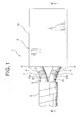
Fig. 1 ] A top view showing a wiring harness according to an embodiment of the present invention. - [
Fig. 2 ] A side view showing the wiring harness shown inFig. 1 . - [
Fig. 3 ] A sectional view taken on line III-III inFig. 1 . -
- 1
- wiring harness
- 2
- electric wire
- 2a
- end of the electric wire
- 3
- connector
- 6
- first marker
- 7
- second marker
- 21
- core wire
- 22
- cover
- 22a
- outer surface of the cover
- A
- color (first marker, second marker)
- N
- mono color (outer surface of the cover)
- Hereinafter, a
wiring harness 1 according to an embodiment of the present invention will be explained with reference toFigs. 1 to 3 . Thewiring harness 1 according to the embodiment of the present invention is, for example, routed in a vehicle as a moving body. As shown inFig. 1 , thewiring harness 1 includes: anelectric wire 2; aconnector 3; anexterior tape 5 as an exterior trim part; a first marker 6 (Fig. 3 ); and asecond marker 7. - A plurality of electric wires (two in
Fig. 1 ) is provided. Theelectric wire 2 is a so-called covered electric wire and a low-voltage electric wire, for example, used in a low voltage circuit in a vehicle. As shown inFig. 3 , theelectric wire 2 includes: aconductive core wire 21; and an insulatingcover 22. Thecore wire 21 is made of a plurality ofelemental wires 21a being stranded. Theelemental wire 21a composing thecore wire 21 is made of conductive metal such as copper, aluminum, or the like. Further, thecore wire 21 may be composed of a singleelemental wire 21a. - The
cover 22 is composed of a resin composition including: a base resin made of such as polyvinyl chloride resin, polypropylene resin, polyethylene resin, or the like; and various additive agents (stabilizing agent such as antioxidizing agent or light stabilizer, flame retardant, antistatic agent, bulking agent, coloring agent, or the like). Thecover 22 covers an outer periphery of thecore wire 21. Therefore, anouter surface 22a of thecover 22 is an outer surface of theelectric wire 22. Thecover 22 is partially removed at anend 2a (Fig. 3 ) of theelectric wire 2, and thecore wire 21 is exposed. - The
outer surface 22a of thecover 22 is colored in mono color N (indicated by white blank inFigs. 1 to 3 ). A desired coloring material may be mixed with the resin component composing thecover 22 so as to make the color of theouter surface 22a of thecover 22 be the mono color N, or alternatively, the mono color N may be set as the color of the resin component itself without adding a coloring material to the resin material composing thecover 22. In the latter case that the mono color N is the color of the resin component itself, theouter surface 22a of thecover 22 is called color free. Thus, the color free means that the color of theouter surface 22a of thecover 22 is the color of the resin component itself without adding the coloring material to the resin component composing thecover 22. - As shown in
Fig. 3 , theconnector 3 is attached to theend 2a of theelectric wire 2, and receives theend 2a of theelectric wire 2 therein. Theconnector 3 includes: aconnector housing 30; and a terminal 40. Theconnector housing 30 is made of insulating synthetic resin, and formed in a tubular shape. Aterminal receiving chamber 31 and alocking lance 32 are provided in theconnector housing 30. Theterminal receiving chamber 31 is a hole extending straight. A terminal 40 is inserted into theterminal receiving chamber 31 from oneend 31a. Theterminal receiving chamber 31 receives the terminal 40 and the oneend 2a of theelectric wire 2 to which the terminal 40 is attached. - The locking
lance 32 is formed in an arm shape, and extended along a longitudinal direction of the terminal 40 received in theterminal receiving chamber 31. One end of the lockinglance 32 near the oneend 31a of theterminal receiving chamber 31 is continued to an outer wall of theconnector housing 30, and the other end of the lockinglance 32 away from the oneend 31a is a free end. A lockingprojection 32a projected into an interior of theterminal receiving chamber 31 is formed on the free end. When the terminal 40 is inserted into theterminal receiving chamber 31 from the oneend 31a, the lockingprojection 32a abuts on the terminal 40, and the lockinglance 32 is elastically deformed in a direction outside of theconnector housing 30. Further, when the terminal 40 is received in theterminal receiving chamber 31, the lockingprojection 32a is disposed in a later-described locking hole of the terminal 40, and the lockinglance 32 is elastically restored. The lockinglance 32 locks the terminal 40 in theterminal receiving chamber 31 - The terminal 40 is made by folding a conductive metal plate or the like. The terminal 40 is a so-called female type terminal. The terminal 40 integrally includes: an
electric contact part 41; and awire connecting part 42. Theelectric contact part 41 includes: atube part 43; a locking hole; and an elastic piece (not shown). Thetube part 43 is formed in a rectangular tube shape. A terminal of a mating connector (hereinafter referred to as a mating terminal) is inserted into thetube part 43 from oneend 43a away from thewire connecting part 42. The locking hole is formed by penetrating thetube part 43. The lockingprojection 32a of the lockinglance 32 is inserted into the locking hole. - The elastic piece is provided in the
tube part 43. The elastic piece is continued to an outer wall of thetube part 43 at the oneend 43a side, and extended in a direction approaching thewire connecting part 42. The elastic piece is elastically deformable in a direction approaching the outer wall. The elastic piece push the mating terminal 40 inserted into thetube part 43 toward an inner wall of thetube part 43 to clip the mating terminal 40 between the inner wall and the elastic piece. When the elastic piece clips the mating terminal 40 between the inner wall and the elastic piece, the mating terminal 40 is held in theelectric contact part 41, and the terminal 40 and the mating terminal 40 are electrically connected to each other. - The
wire connecting part 42 includes: abottom plate part 46; and a crimpingpiece 47. Thebottom plate part 46 is formed in a substantially band shape, and theelectric wire 2 is positioned on an outer surface of thebottom plate part 46. A plurality of crimpingpieces 47 are provided at both ends of thebottom plate part 46 in a width direction. The crimping pieces are bent in a direction approaching thebottom plate part 46, and clip theelectric wire 2 between the crimping piece and thebottom plate part 46 to crimp theelectric wire 2. When the crimping pieces crimp theelectric wire 2, theelectric wire 2 is attached to thewire connecting part 42, and the terminal 40 and theelectric wire 2 are electrically connected to each other. - The
exterior tape 5 includes: a tape material made of such as polyvinyl chloride resin; and an adhesive material applied to one outer surface of the tape material. Theexterior tape 5 is so wrapped around theelectric wire 2 that the first andsecond markers exterior tape 5 bundles a plurality ofelectric wires 2 into one piece, and prevents theelectric wire 2 from being damaged by contacting a vehicle panel or the like when thewiring harness 1 is routed in a vehicle. - As shown in
Fig. 3 , thefirst marker 6 is formed on theouter surface 22a of thecover 22 of theelectric wire 2 received in theconnector 3. Thefirst marker 6 is formed on an area S (Fig. 3 ) between a border b1 between thecover 22 and the terminal 40, and a border b2 between thecover 22 and theconnector 3. Thefirst marker 6 is formed in a ring shape, and formed over a whole periphery of thecover 22. A length of thefirst marker 6 in a longitudinal direction of thecover 22 is shorter than a length of the area S1 in the longitudinal direction of thecover 22. Namely, a whole of thefirst marker 6 is received in the connector 3 (terminal receiving chamber 31). Thefirst marker 6 is formed by coloring a part of theouter surface 22a of thecover 22 in a color A (indicated by parallel diagonal lines inFig. 3 ) different from the color of theouter surface 22a (mono color N). - As shown in
Fig. 3 , thesecond marker 7 is formed on the22aouter surface 22a of thecover 22 of theelectric wire 2 exposed to an outside of theconnector 3. Thesecond marker 7 is formed on an area S2 (Fig. 3 ) between the border b2 between thecover 22 and theconnector 3 and a border b3 between thecover 22 and theexterior tape 5. Namely, thesecond marker 7 is formed on a position which can be seen from an outside. A shape of thesecond marker 7 is the same as thefirst marker 6. Thesecond marker 7 is formed in a ring shape, and formed over a whole periphery of thecover 22. A length of thesecond marker 7 in the longitudinal direction of thecover 22 is the same as the length of thefirst marker 6 in the longitudinal direction of thecover 22. Thesecond marker 7 is formed by coloring a part of the22aouter surface 22a of thecover 22 in a color (indicated by parallel diagonal lines inFigs. 1 to 3 ) the same as the color A of thefirst marker 6. Thefirst marker 6 and thesecond marker 7 are disposed with a gap in the longitudinal direction of thecover 22. Incidentally, only two markers of the first andsecond markers end 2a side of theelectric wire 2. Further, in this embodiment, a length of the area S2 in the longitudinal direction of thecover 22 is not more than 10 mm. - By changing the color A of the first and
second markers electric wires 2 can be distinguished from each other. For example, the inventors of the present invention use twelve colors including the color A. Due to the color A of the first andsecond markers electric wire 2 or a system of thewiring harness 1 can be distinguished. Namely, due to the color A of the first andsecond marker electric wire 2 of thewiring harness 1 can be distinguished. Therefore, when at least one of the first andsecond marker electric wire 2 of thewiring harness 1 can be distinguished. - Further, the first and
second markers 04/015720 - The coloring liquid is a liquid, in which a dye is dissolved or dispersed in a solvent. The coating material is a material, in which a pigment is dispersed in a liquid dispersion. Therefore, when the coloring liquid adheres to the
outer surface 22a of thecover 22, the dye permeates into thecover 22. When the coating material adheres to theouter surface 22a of thecover 22, the pigment adheres to theouter surface 22a without permeating into thecover 22. Preferably, the solvent and liquid dispersion have an affinity to the synthetic resin that constitutes thecover 22 in order to securely permeate the dye into thecover 22 or to allow the pigment to securely adhere to theouter surface 22a. As described above, to color theouter surface 22a of thecover 22 means to dye a part of theouter surface 22a of thecover 22 with a dye or to coat a part of theouter surface 22a of thecover 22 with a pigment. - When assembling the
wiring harness 1 having the above-described structure, firstly, a longelectric wire 2 having no marker is cut in a specific length. Then, the first andsecond marker electric wire 2 with the well-known marking apparatus described above. At this time, because only the first andsecond markers end 2a side of theelectric wire 2, the marking (coloring) operation can be simplified. Next, a part of thecover 22 at the oneend 2a of theelectric wire 2 is removed and thecore wire 21 is exposed. Then, the terminal 40 is attached to the exposedcore wire 21. - Then, the terminal 40 is inserted into the
terminal receiving chamber 31 of theconnector housing 30. At this time, thefirst marker 6 is disposed in theterminal receiving chamber 31, namely, in theconnector 3. Thesecond marker 7 is disposed outside of theterminal receiving chamber 31, namely, outside of theconnector 3. Then, theexterior tape 5 is wrapped in a direction away from theconnector 3 from a vicinity of thesecond marker 7 so that thesecond marker 7 is exposed. Thus, thewiring harness 1 is assembled. Then, thewiring harness 1 is wired in a desired shape on a wiring board, and then routed in a vehicle. - Normally, the
second marker 7 is used for distinguishing theelectric wire 2 of thewiring harness 1 assembled as described above. However, because thesecond marker 7 is exposed outside, thesecond marker 7 may be removed due to an external factor, for example, the marker is grazed on theexterior tape 5, peripheral parts, a vehicle body panel, or the like when a wiring work or a routing work is operated. In contrast, because thefirst marker 6 is arranged in theconnector 3, thefirst marker 6 is not removed due to the external factor. Accordingly, when thesecond marker 7 is removed, the terminal 40 is pulled out from theterminal receiving chamber 31 using a jig or the like so that thefirst marker 6 is used for distinguishing theelectric wire 2. Thus, theelectric wire 2 can be distinguished at any time. - According to this embodiment, the
wiring harness 1 includes: thefirst marker 6 formed by coloring a part of theouter surface 22a of thecover 22 of theelectric wire 2 received in theconnector 3 in a color A different from the mono color N of theouter surface 22a; and thesecond marker 7 formed by coloring a part of theouter surface 22a of thecover 22 of theelectric wire 2 exposed to an outside of theconnector 3 in the color A the same as thefirst marker 6. Therefore, thefirst marker 6 is prevented from being removed due to an external factor. Normally, theelectric wire 2 is distinguished using thesecond marker 7, and when thesecond marker 7 is removed due to the external factor, theelectric wire 2 is distinguished using thefirst marker 6. Accordingly, at least thefirst marker 7 is prevented from being removed, thereby theelectric wire 2 can be surely distinguished at any time. - The first and
second markers cover 22. Therefore, it is rare that these markers are completely removed. In particular, thesecond marker 7 is prevented from being removed, thereby theelectric wire 2 can be surely distinguished. - According to this embodiment, the first and
second markers cover 22. However, it is not necessary that the first andsecond markers cover 22. Further, according to this embodiment, theexterior tape 5 as the exterior trim part is attached to theelectric wire 2. However, a corrugate tube (tube for harness), a protector for harness, a grommet for harness, a clip for wiring, or the like can be used as the exterior trim part. - Further, according to this embodiment, the
wiring harness 1 for routing in a vehicle is described. However, thewiring harness 1 may be used for various electronic devices such as a portable computer, or for various electric machines. Further, according to this embodiment, twoelectric wires 2 are provided. However, the number of theelectric wire 2 may be one or more than two. Further, according to this embodiment, the terminal 40 is a female type terminal. However, the terminal 40 may be a male type terminal. Further, according to the present invention, various materials may be used as the coloring liquid or coating material such as acrylic coating material, ink (dye or pigment) and UV-ink. - Although the present invention has been fully described by way of example with reference to the accompanying drawings, it is to be understood that various changes and modifications will be apparent to those skilled in the art. Therefore, unless otherwise such changes and modifications depart from the scope of the present invention hereinafter defined, they should be construed as being included therein.
Claims (2)
- A wiring harness including: an electric wire having a conductive core wire and an insulating cover for covering the core wire; and a connector attached to an end of the electric wire for receiving the end of the electric wire therein,
characterized in that the wiring harness further includes:a first marker formed by coloring a part of an outer surface of the cover of the electric wire received in the connector in a color different from a color of the outer surface; anda second marker formed by coloring a part of the outer surface of the cover of the electric wire exposed to an outside of the connector in a color the same as the first marker. - The wiring harness
characterized in that the first and second markers are formed over a whole periphery of the cover.
Applications Claiming Priority (2)
| Application Number | Priority Date | Filing Date | Title |
|---|---|---|---|
| JP2008102137A JP5416358B2 (en) | 2008-04-10 | 2008-04-10 | Wire harness |
| PCT/JP2008/073304 WO2009125524A1 (en) | 2008-04-10 | 2008-12-22 | Wire harness |
Publications (2)
| Publication Number | Publication Date |
|---|---|
| EP2267727A1 true EP2267727A1 (en) | 2010-12-29 |
| EP2267727A4 EP2267727A4 (en) | 2013-01-23 |
Family
ID=41161662
Family Applications (1)
| Application Number | Title | Priority Date | Filing Date |
|---|---|---|---|
| EP08873806A Withdrawn EP2267727A4 (en) | 2008-04-10 | 2008-12-22 | CABLE BEAM |
Country Status (5)
| Country | Link |
|---|---|
| US (1) | US8513526B2 (en) |
| EP (1) | EP2267727A4 (en) |
| JP (1) | JP5416358B2 (en) |
| CN (1) | CN102047348A (en) |
| WO (1) | WO2009125524A1 (en) |
Cited By (1)
| Publication number | Priority date | Publication date | Assignee | Title |
|---|---|---|---|---|
| CN103890864A (en) * | 2011-10-25 | 2014-06-25 | 矢崎总业株式会社 | Wires and Harnesses |
Families Citing this family (11)
| Publication number | Priority date | Publication date | Assignee | Title |
|---|---|---|---|---|
| MX2012010073A (en) * | 2010-03-02 | 2012-10-03 | Yazaki Corp | Wiring harness and manufacturing method thereof. |
| WO2013151185A1 (en) * | 2012-04-04 | 2013-10-10 | Yazaki Corporation | Terminal-attached electric wire |
| KR101488465B1 (en) * | 2012-10-23 | 2015-01-30 | 후루카와 덴키 고교 가부시키가이샤 | Terminal connection structure for coated electric wire, wiring harness, and terminal connection method for coated electric wire |
| JP6322377B2 (en) * | 2013-10-04 | 2018-05-09 | 矢崎総業株式会社 | Wire harness production system and wire harness production method |
| JP2015111536A (en) * | 2013-11-01 | 2015-06-18 | 住友電装株式会社 | Electric wire with identification display |
| JP2016149249A (en) * | 2015-02-12 | 2016-08-18 | 株式会社オートネットワーク技術研究所 | Exterior wire harness |
| JP2017130369A (en) * | 2016-01-21 | 2017-07-27 | 矢崎総業株式会社 | Electric wire and wire harness using the same |
| JP6701525B2 (en) * | 2016-11-24 | 2020-05-27 | 株式会社オートネットワーク技術研究所 | Crimping terminal, electric wire with terminal, and method for manufacturing electric wire with terminal |
| WO2019028087A1 (en) * | 2017-07-31 | 2019-02-07 | Ppc Broadband, Inc. | Coaxial drop cable with circumferential segmented floodant locations |
| JP2021068520A (en) * | 2019-10-18 | 2021-04-30 | 矢崎総業株式会社 | Method for inserting electric wire with terminal into connector |
| US12626616B2 (en) * | 2023-09-15 | 2026-05-12 | Vaughn Lee Ennis | Color-coded cable and ethernet port identification labels |
Family Cites Families (15)
| Publication number | Priority date | Publication date | Assignee | Title |
|---|---|---|---|---|
| JPS5853314A (en) | 1981-09-24 | 1983-03-29 | Mitsubishi Heavy Ind Ltd | Multistage cluster rolling mill |
| JPS5853314U (en) * | 1981-09-29 | 1983-04-11 | 松下電器産業株式会社 | wiring device |
| US4781619A (en) * | 1987-09-18 | 1988-11-01 | Yazaki Corporation | Connector and method of connecting wires thereto |
| JP2942983B2 (en) * | 1995-05-25 | 1999-08-30 | モレックス インコーポレーテッド | Wire binding device |
| JPH1127817A (en) | 1997-07-07 | 1999-01-29 | Harness Sogo Gijutsu Kenkyusho:Kk | Circuit identification method for wire harness |
| JP2001245426A (en) * | 2000-02-29 | 2001-09-07 | Sumitomo Wiring Syst Ltd | Clamp and connector-fixing structure for wire harness using the clamp |
| US6672895B2 (en) * | 2001-11-26 | 2004-01-06 | Cardiac Pacemakers, Inc. | Marking system for lead connector and header |
| EP1321191B1 (en) * | 2001-11-27 | 2007-01-24 | Yazaki Corporation | Method for recycling waste wire harness |
| JP2003229225A (en) | 2002-01-31 | 2003-08-15 | Sumitomo Wiring Syst Ltd | Inspection method of electric wire connection to connector |
| US20060118325A1 (en) | 2002-08-09 | 2006-06-08 | Kiyoshi Yagi | Electric wire and wire harness |
| US7462780B2 (en) * | 2003-01-17 | 2008-12-09 | Bell Helicopter Textron Inc. | Molded electronic assembly |
| JP4522053B2 (en) * | 2003-05-07 | 2010-08-11 | 矢崎総業株式会社 | Electric wire, electric wire connection method, and wire harness |
| JP2005347101A (en) | 2004-06-03 | 2005-12-15 | Sumitomo Wiring Syst Ltd | Covered cable |
| FR2887069B1 (en) * | 2005-06-14 | 2016-09-09 | Airbus France | ELECTRICAL CABLE WITH EXTERNAL MARKING AND METHOD OF CRIMPING A TEST OF A CONTACT ON AN ELECTRICAL CABLE WITH EXTERNAL MARKING |
| JP2008269892A (en) * | 2007-04-18 | 2008-11-06 | Sumitomo Electric Ind Ltd | Electrical insulation cable |
-
2008
- 2008-04-10 JP JP2008102137A patent/JP5416358B2/en not_active Expired - Fee Related
- 2008-12-22 CN CN200880129473.4A patent/CN102047348A/en active Pending
- 2008-12-22 EP EP08873806A patent/EP2267727A4/en not_active Withdrawn
- 2008-12-22 US US12/736,407 patent/US8513526B2/en not_active Expired - Fee Related
- 2008-12-22 WO PCT/JP2008/073304 patent/WO2009125524A1/en not_active Ceased
Cited By (1)
| Publication number | Priority date | Publication date | Assignee | Title |
|---|---|---|---|---|
| CN103890864A (en) * | 2011-10-25 | 2014-06-25 | 矢崎总业株式会社 | Wires and Harnesses |
Also Published As
| Publication number | Publication date |
|---|---|
| EP2267727A4 (en) | 2013-01-23 |
| US20110024157A1 (en) | 2011-02-03 |
| JP2009252663A (en) | 2009-10-29 |
| WO2009125524A1 (en) | 2009-10-15 |
| JP5416358B2 (en) | 2014-02-12 |
| US8513526B2 (en) | 2013-08-20 |
| CN102047348A (en) | 2011-05-04 |
Similar Documents
| Publication | Publication Date | Title |
|---|---|---|
| US8513526B2 (en) | Wiring harness | |
| CN105322316B (en) | Wire harness | |
| CN105684101B (en) | Electric wire with identification display | |
| US10290395B2 (en) | Conductive path protection structure | |
| JP2016004686A (en) | Wire harness | |
| WO2020208885A1 (en) | Wiring member | |
| US20120312596A1 (en) | Wiring harness and manufacturing method thereof | |
| US9672960B2 (en) | Exterior member and electric wire wiring structure | |
| US7275317B2 (en) | Method of production for a wiring harness job order | |
| EP1630827B1 (en) | Wire harness assembling device and wire harness assembling method | |
| US12278027B2 (en) | Wiring member and method of manufacturing the wiring member | |
| US11501894B2 (en) | Wiring member | |
| JP2003168329A (en) | Covered electric wire | |
| JP2009301944A (en) | Adhesive tape to be wound around electric wires, and wire harness wound with the adhesive tape | |
| JP2014038852A (en) | Wiring harness | |
| JPH1032913A (en) | Wiring assembly | |
| US20250157691A1 (en) | Wire harness arrangement structure | |
| JP2009296693A (en) | Wire harness fixing structure | |
| JP2019009945A (en) | Wire packaging sheet for electric connection box, and manufacturing method of electric connection box employing the same | |
| JP2015072861A (en) | Wire harness production system and wire harness production method | |
| JPH07254313A (en) | Identification method for covered conductor | |
| JP2005259366A (en) | Flat cable | |
| WO2013061714A1 (en) | Electric wire and wire harness | |
| JP2009055725A (en) | Wire structure |
Legal Events
| Date | Code | Title | Description |
|---|---|---|---|
| PUAI | Public reference made under article 153(3) epc to a published international application that has entered the european phase |
Free format text: ORIGINAL CODE: 0009012 |
|
| 17P | Request for examination filed |
Effective date: 20101006 |
|
| AK | Designated contracting states |
Kind code of ref document: A1 Designated state(s): AT BE BG CH CY CZ DE DK EE ES FI FR GB GR HR HU IE IS IT LI LT LU LV MC MT NL NO PL PT RO SE SI SK TR |
|
| AX | Request for extension of the european patent |
Extension state: AL BA MK RS |
|
| DAX | Request for extension of the european patent (deleted) | ||
| A4 | Supplementary search report drawn up and despatched |
Effective date: 20121221 |
|
| RIC1 | Information provided on ipc code assigned before grant |
Ipc: H01B 7/36 20060101ALI20121217BHEP Ipc: H02G 1/06 20060101ALI20121217BHEP Ipc: H01B 7/00 20060101AFI20121217BHEP |
|
| 17Q | First examination report despatched |
Effective date: 20131031 |
|
| STAA | Information on the status of an ep patent application or granted ep patent |
Free format text: STATUS: THE APPLICATION IS DEEMED TO BE WITHDRAWN |
|
| 18D | Application deemed to be withdrawn |
Effective date: 20160224 |