EP2267611A2 - Amplitude computing apparatus and method - Google Patents
Amplitude computing apparatus and method Download PDFInfo
- Publication number
- EP2267611A2 EP2267611A2 EP10251123A EP10251123A EP2267611A2 EP 2267611 A2 EP2267611 A2 EP 2267611A2 EP 10251123 A EP10251123 A EP 10251123A EP 10251123 A EP10251123 A EP 10251123A EP 2267611 A2 EP2267611 A2 EP 2267611A2
- Authority
- EP
- European Patent Office
- Prior art keywords
- value
- amplitude
- input signal
- computing
- distribution
- Prior art date
- Legal status (The legal status is an assumption and is not a legal conclusion. Google has not performed a legal analysis and makes no representation as to the accuracy of the status listed.)
- Withdrawn
Links
Images








Classifications
-
- G—PHYSICS
- G06—COMPUTING OR CALCULATING; COUNTING
- G06F—ELECTRIC DIGITAL DATA PROCESSING
- G06F17/00—Digital computing or data processing equipment or methods, specially adapted for specific functions
- G06F17/10—Complex mathematical operations
- G06F17/18—Complex mathematical operations for evaluating statistical data, e.g. average values, frequency distributions, probability functions, regression analysis
-
- G—PHYSICS
- G01—MEASURING; TESTING
- G01S—RADIO DIRECTION-FINDING; RADIO NAVIGATION; DETERMINING DISTANCE OR VELOCITY BY USE OF RADIO WAVES; LOCATING OR PRESENCE-DETECTING BY USE OF THE REFLECTION OR RERADIATION OF RADIO WAVES; ANALOGOUS ARRANGEMENTS USING OTHER WAVES
- G01S17/00—Systems using the reflection or reradiation of electromagnetic waves other than radio waves, e.g. lidar systems
- G01S17/02—Systems using the reflection of electromagnetic waves other than radio waves
- G01S17/50—Systems of measurement based on relative movement of target
Definitions
- the present invention relates to an amplitude computing apparatus, which computes the amplitude of a signal that changes sinusoidally, and an amplitude computing method.
- the probability distribution function of a displacement X is given as 1/cos ⁇ asin( X ) ⁇ , as shown in FIG. 9 .
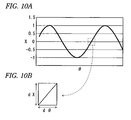
- FIG 10B shows part of the sine wave in FIG. 10A . In FIG.
- FIG. 11 shows the frequency distribution when the mean position (i.e., the center) was 400, the amplitude was 200, and the positions of the target that vibrates were randomly generated; it is evident that the frequency distribution from the center 400 to the maximum value 500 coincides with the probability density function shown in FIG. 9 .
- each target positional data value contains error, and the error distribution can be regarded as a normal distribution. Accordingly, the frequency distribution of the positions including error is shown in FIG. 12 .
- the amplitude value 220 i.e., the maximum value - the minimum value
- the conventional method of deriving the amplitude of a vibration using the maximum value and the minimum value of the position cannot eliminate the effects of noise, tends to make an overly high estimate of the amplitude, and cannot predict error, which are problems.
- an apparatus for determining the amplitude of an input signal that changes sinusoidally comprising: a representative value computing unit configured to compute a statistical representative value of a distribution of the input value that is sampled, wherein the statistical representative value includes at least one of a mean value, a median value, mode value, a standard deviation and quartiles; and an amplitude computing unit configured to compute the amplitude of the input signal based on the statistical representative value.
- an amplitude computing apparatus including: a mean or median value computing unit configured to compute a mean or median value of a distribution of an input signal that changes sinusoidally; a mode value computing unit configured to compute a mode value of the distribution of the input signal; and an amplitude computing unit configured to compute a difference between the mean or median value and the mode value as an amplitude of the input signal.
- an amplitude computing apparatus including: a standard deviation computing unit configured to compute a standard deviation of a distribution of an input signal that changes sinusoidally; and an amplitude computing unit configured to compute a value of ⁇ 2 times the standard deviation as an amplitude of the input signal.
- an amplitude computing apparatus including: a quartile computing unit configured to compute quartiles of a distribution of an input signal that changes sinusoidally; and an amplitude computing unit configured to compute a value of ⁇ 2 times a difference between either of a first quartile or a third quartile among the quartiles and a second quartile as an amplitude of the input signal.
- an amplitude computing apparatus including: a quartile computing unit configured to compute quartiles of a distribution of an input signal that changes sinusoidally; a mean value computing unit configured to compute a mean value of the distribution of the input signal; and an amplitude computing unit configured to compute a value of ⁇ 2 times a difference between either of a first quartile or a third quartile among the quartiles and the mean value as an amplitude of the input signal.
- a method of determining the amplitude of an input signal that changes sinusoidally comprising: computing a statistical representative value of a distribution of the input value that is sampled, wherein the statistical representative value includes at least one of a mean value, a median value, mode value, a standard deviation and quartiles; and computing the amplitude of the input signal based on the statistical representative value.
- an amplitude computing method including: computing a mean or median value of a distribution of an input signal that changes sinusoidally; computing a mode value of the distribution of the input signal; and computing a difference between either of the mean or median value and the mode value as an amplitude of the input signal.
- an amplitude computing method including: computing a standard deviation of a distribution of an input signal that changes sinusoidally; and computing a value of ⁇ 2 times the standard deviation as an amplitude of the input signal.
- an amplitude computing method including: computing quartiles of a distribution of an input signal that changes sinusoidally; and computing a value of ⁇ 2 times a difference between either of a first quartile or a third quartile among the quartiles and a second quartile as an amplitude of the input signal.
- an amplitude computing method including: computing quartiles of a distribution of an input signal that changes sinusoidally; computing a mean value of the distribution of the input signal; and computing a value of ⁇ 2 times a difference between either of a first quartile or a third quartile among the quartiles and the mean value as an amplitude of the input signal.
- computing the difference between the mean or median value and the mode value of the input signal as the amplitude makes it possible to reduce amplitude error more than in the conventional method wherein the amplitude is defined as the difference between the maximum value and the minimum value.
- computing quartiles of a distribution of an input signal and computing a value of ⁇ 2 times the difference between a first quartile or a third quartile among the quartiles and a second quartile as the amplitude makes it possible to reduce amplitude error more than in the conventional method wherein the amplitude is defined as the difference between the maximum value and the minimum value.
- computing quartiles and a mean value of a distribution of an input signal and computing a value of ⁇ 2 times the difference between a first quartile or a third quartile among the quartiles and the mean value as an amplitude makes it possible to reduce amplitude error more than in the conventional method wherein the amplitude is defined as the difference between the maximum value and the minimum value.
- FIG. 1 is a block diagram that shows the configuration of an amplitude computing apparatus according to an embodiment of the present invention.
- the amplitude computing apparatus has a storage unit 10, and a representative value computing unit in the form of a mean value computing unit 11 and a mode value computing unit 12, and an amplitude computing unit 13.
- the difference between the mean and the mode is the semi-amplitude, even if each individual value includes error. If the sampling interval is uniform and the number of observations included in the times that fall within the lowest common multiple of the sampling interval and the sinusoidal period is sufficiently large, then the sampling of the values along the sinusoidal track can be considered uniform. If the sampling interval is not uniform or if the number of observations included in the times that fall within the lowest common multiple of the sampling interval and the sinusoidal period is small, then the sampling of the values along the sinusoidal track cannot be considered uniform and, consequently, in such a case, the present embodiment is not effective.
- FIG. 2 is a flow chart that shows the operation of the amplitude computing apparatus according to the present embodiment.
- a positional data signal of, for example, an object that vibrates is input as a time series to the amplitude computing apparatus of the present embodiment.
- the positional data signal can be obtained by a laser displacement measuring instrument, as discussed above.
- the positional data signal is a discrete signal produced by sampling at fixed time intervals.
- the storage unit 10 stores the signal that is input.
- the mean value computing unit 11 computes the mean value of the distribution of the signal stored in the storage unit 10 (i.e., step S10 in FIG. 2 ).
- the mean value computed by the mean value computing unit 11 is stored in the storage unit 10.
- the mode value computing unit 12 computes the mode value of the distribution of the signal stored in the storage unit 10 (i.e., step S11) .
- the mode value computed by the mode value computing unit 12 is stored in the storage unit 10.
- the mode value corresponds to the maximum value or the minimum value of the signal.
- the amplitude computing unit 13 computes the difference between the mean value and the mode value as the semi-amplitude of the signal (i.e., step S12). Furthermore, if (mean > mode), then the semi-amplitude should be defined as (mean - mode); furthermore, if (mode > mean), then the semi-amplitude should be defined as (mode - mean). It goes without saying that twice the value of the semi-amplitude is the amplitude (i.e., the peak-to-peak amplitude).
- computing the difference between the mean value and the mode value of the signal as the semi-amplitude makes it possible to reduce amplitude error more than in the conventional method wherein the amplitude is defined as the difference between the maximum value and the minimum value.
- the semi-amplitude of the signal is defined as the difference between the mean and the mode of the signal, but the semi-amplitude of the signal may be defined as the difference between the distribution median and the mode of the signal.
- a median value computing unit may be used instead of the mean value computing unit 11, and the amplitude computing unit 13 may compute the difference between the median value and the mode value as the semi-amplitude of the signal.
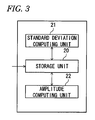
- FIG. 3 is a block diagram that shows the configuration of the amplitude computing apparatus according to the other embodiment of the present invention.
- the amplitude computing apparatus includes a storage unit 20, a standard deviation computing unit 21, and an amplitude computing unit 22.
- FIG. 4 is a flow chart that shows the operation of the amplitude computing apparatus of the present embodiment.
- the storage unit 20 stores the positional data signal, which is input as a time series.
- the standard deviation computing unit 21 computes the standard deviation of the distribution of the signal stored in the storage unit 20 (i.e., step S20 in FIG. 4 ).
- the standard deviation computed by the standard deviation computing unit 21 is stored in the storage unit 20.
- the amplitude computing unit 22 computes the value of ⁇ 2 ( ⁇ 1.414) times the standard deviation as the semi-amplitude of the signal (i.e., step S21).
- FIG. 5 is a block diagram that shows the configuration of the amplitude computing apparatus according to this embodiment of the present invention.
- the amplitude computing apparatus includes a storage unit 30, a quartile computing unit 31, and an amplitude computing unit 32.
- the basic principle of the present embodiment is the same as that of the above embodiment; however, instead of the reference being defined as the standard deviation, the reference is defined as a first quartile, which has less error.
- the difference between the first quartile and the mean is given as 1/ ⁇ 2 ( ⁇ 0.707) times the semi-amplitude and, consequently, if the first quartile of the distribution of the sampled values is derived and multiplied by ⁇ 2, then the result is the semi-amplitude.
- FIG. 6 is a flow chart that shows the operation of the amplitude computing apparatus of the present embodiment.
- the storage unit 30 stores the positional data signal, which is input as a time series.
- the quartile computing unit 31 computes the quartiles of the distribution of the signal stored in the storage unit 30 (i.e., step S30 in FIG. 6 ).
- the amplitude computing unit 32 computes the value of ⁇ 2 ( ⁇ 1.414) times the difference between the second quartile (i.e., the median) and either the first quartile or the third quartile of the computed quartiles as the semi-amplitude of the signal (i.e., step S31). For example, in the example shown in FIG. 12 , the first quartile is 330, the second quartile is 400, and the third quartile is 470.
- the above embodiments require a sample of sufficient uniformity and size for the frequency distribution of the signal to be regarded as 1/cos ⁇ asin( X ) ⁇ (wherein X is the displacement); in addition, because the frequency changes sharply in the vicinity of the maximum amplitude, error tends to be incorporated therein; however, the quartiles tend not to be affected by sample uniformity, outliers, and the like. As such, according to the present embodiment, amplitude error can be reduced even more than in the previous embodiments.
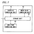
- FIG. 7 is a block diagram that shows the configuration of the amplitude computing apparatus according to the embodiment of the present invention.
- the amplitude computing apparatus includes a storage unit 40, a quartile computing unit 41, a mean value computing unit 42, and an amplitude computing unit 43.
- the present embodiment uses the mean value instead of the second quartile (i.e., the median) used in the above embodiment.
- FIG. 8 is a flow chart that shows the operation of the amplitude computing apparatus of the present embodiment.
- the storage unit 40 stores the positional data signal, which is input as a time series.
- the quartile computing unit 41 computes the quartiles of the distribution of the signal stored in the storage unit 40 (i.e., step S40 in FIG. 8 ).
- the mean value computing unit 42 computes the mean value of the distribution of the signal stored in the storage unit 40 (i.e., step S41).
- the mean computed by the mean value computing unit 42 is stored in the storage unit 40.
- the amplitude computing unit 43 computes the value of ⁇ 2 times the difference between the mean and the first quartile or the third quartile among the computed quartiles as the semi-amplitude of the signal (i.e., step S42).
- the amplitude computing apparatus in the above embodiments can be implemented by a program that controls: a computer, which has, for example, a CPU, a storage, and an interface; and hardware resources thereof.
- the program for controlling such a computer may be recorded on a storage medium, such as a flexible disk, a CD-ROM, a DVD-ROM, or a memory card.
- the CPU writes the program, which was read in, to the storage apparatus and, in accordance with the program, executes the processes explained in the above embodiments.
- the embodiments explain an exemplary case wherein a signal that is input serves as the positional data signal of the object that vibrates, but the present invention is not limited thereto.
- the present invention can be adapted to other cases as long as the signal that is input to the amplitude computing apparatus is a discrete signal obtained by sampling a sinusoidal signal.
- the present invention can be adapted to a technology that computes the amplitude of a signal that changes sinusoidally.
- Constituent components disclosed in the aforementioned embodiments may be combined suitably to form various modifications. For example, some of all constituent components disclosed in one of the embodiments may be removed or the constituent components disclosed in different embodiments may be appropriately combined.
Landscapes
- Engineering & Computer Science (AREA)
- Physics & Mathematics (AREA)
- Data Mining & Analysis (AREA)
- General Physics & Mathematics (AREA)
- Mathematical Optimization (AREA)
- Pure & Applied Mathematics (AREA)
- Theoretical Computer Science (AREA)
- Mathematical Physics (AREA)
- Computational Mathematics (AREA)
- Mathematical Analysis (AREA)
- Databases & Information Systems (AREA)
- Operations Research (AREA)
- Probability & Statistics with Applications (AREA)
- Bioinformatics & Cheminformatics (AREA)
- Algebra (AREA)
- Evolutionary Biology (AREA)
- Life Sciences & Earth Sciences (AREA)
- Software Systems (AREA)
- General Engineering & Computer Science (AREA)
- Bioinformatics & Computational Biology (AREA)
- Measurement Of Current Or Voltage (AREA)
- Measurement Of Mechanical Vibrations Or Ultrasonic Waves (AREA)
- Analogue/Digital Conversion (AREA)
Abstract
Description
- The present invention relates to an amplitude computing apparatus, which computes the amplitude of a signal that changes sinusoidally, and an amplitude computing method.
- A laser displacement measuring instrument can measure the position of a target that vibrates. Because the difference between the maximum value and the minimum value of the position of the target is the amplitude of the vibrational motion of the target, the amplitude can be derived from the maximum and minimum values derived for the target's position (see Application Specific Measurement Guides for a Laser Displacement Meter, Vol. 3: Measurement of Vibrations, p. 2, Keyence Corporation, <http://www.keyence.co.jp/req/h/ avhc3w5/show.jsp?done=/henni/index.jsp&motive=TOP>).
- If the semi-amplitude from the center of the vibration of the target to the maximum value or the minimum value of the displacement is normalized, then the probability distribution function of a displacement X is given as 1/cos{asin(X)}, as shown in
FIG. 9 . As a result, in the ideal state, if the positional data of the target is sampled at discrete times and the sample size is sufficiently large, then the amplitude data of the target can be correctly measured based on the maximum value and the minimum value of the target's position. - Here, the method of deriving the probability distribution function of the displacement X will be explained.
FIG. 10A and 10B are views for explaining the method of deriving the probability distribution function of the displacement X. If X takes on the values in the function sine wave sin(θ·t), then the probability is given as X = sin(θ), and therefore is proportionate to 1/cos(θ), which is the inverse of the slope of sin(θ).FIG 10B shows part of the sine wave inFIG. 10A . InFIG. 10B , the time during which the displacement X is included in dX is dθ, and dX/dθ is cos(θ); therefore, the value of θ when sin(θ) is dX is given as dθ/dX, namely, 1/cos(θ). Furthermore, because sin(θ) = X, θ = asin(X). If we substitute θ = asin(X) in 1/cos(θ), then the probability density function when X takes on the values of the function sin(θ) is proportional to 1/cos{asin(X)}. The above is the method of deriving the probability distribution function of the displacement X . -
FIG. 11 shows the frequency distribution when the mean position (i.e., the center) was 400, the amplitude was 200, and the positions of the target that vibrates were randomly generated; it is evident that the frequency distribution from thecenter 400 to themaximum value 500 coincides with the probability density function shown inFIG. 9 . - Incidentally, each target positional data value contains error, and the error distribution can be regarded as a normal distribution. Accordingly, the frequency distribution of the positions including error is shown in
FIG. 12 . In the example shown inFIG. 12 , the error (i.e., standard deviation = 5) caused by noise is the difference between the position's maximum value 510 andoriginal value 500 as well as the difference between the position's minimum value 290 andoriginal value 300; therefore, the amplitude value 220 (i.e., the maximum value - the minimum value) is approximately 10% larger than the original value 200. - As described above, the conventional method of deriving the amplitude of a vibration using the maximum value and the minimum value of the position cannot eliminate the effects of noise, tends to make an overly high estimate of the amplitude, and cannot predict error, which are problems.
- It is an aim of the present invention to provide an amplitude computing apparatus, which can reduce the amplitude error, and an amplitude computing method.
- According to one aspect of the invention, there is provided an apparatus for determining the amplitude of an input signal that changes sinusoidally, the apparatus comprising: a representative value computing unit configured to compute a statistical representative value of a distribution of the input value that is sampled, wherein the statistical representative value includes at least one of a mean value, a median value, mode value, a standard deviation and quartiles; and an amplitude computing unit configured to compute the amplitude of the input signal based on the statistical representative value.
- According to one or more illustrative aspects of the present invention, there is provided an amplitude computing apparatus including: a mean or median value computing unit configured to compute a mean or median value of a distribution of an input signal that changes sinusoidally; a mode value computing unit configured to compute a mode value of the distribution of the input signal; and an amplitude computing unit configured to compute a difference between the mean or median value and the mode value as an amplitude of the input signal.
- According to one or more illustrative aspects of the present invention, there is provided an amplitude computing apparatus including: a standard deviation computing unit configured to compute a standard deviation of a distribution of an input signal that changes sinusoidally; and an amplitude computing unit configured to compute a value of √2 times the standard deviation as an amplitude of the input signal.
- According to one or more illustrative aspects of the present invention, there is provided an amplitude computing apparatus including: a quartile computing unit configured to compute quartiles of a distribution of an input signal that changes sinusoidally; and an amplitude computing unit configured to compute a value of √2 times a difference between either of a first quartile or a third quartile among the quartiles and a second quartile as an amplitude of the input signal.
- According to one or more illustrative aspects of the present invention, there is provided an amplitude computing apparatus including: a quartile computing unit configured to compute quartiles of a distribution of an input signal that changes sinusoidally; a mean value computing unit configured to compute a mean value of the distribution of the input signal; and an amplitude computing unit configured to compute a value of √2 times a difference between either of a first quartile or a third quartile among the quartiles and the mean value as an amplitude of the input signal.
- According to another aspect of the invention, there is provided a method of determining the amplitude of an input signal that changes sinusoidally, the method comprising: computing a statistical representative value of a distribution of the input value that is sampled, wherein the statistical representative value includes at least one of a mean value, a median value, mode value, a standard deviation and quartiles; and computing the amplitude of the input signal based on the statistical representative value.
- According to one or more illustrative aspects of the present invention, there is provided an amplitude computing method including: computing a mean or median value of a distribution of an input signal that changes sinusoidally; computing a mode value of the distribution of the input signal; and computing a difference between either of the mean or median value and the mode value as an amplitude of the input signal.
- According to one or more illustrative aspects of the present invention, there is provided an amplitude computing method including: computing a standard deviation of a distribution of an input signal that changes sinusoidally; and computing a value of √2 times the standard deviation as an amplitude of the input signal.
- According to one or more illustrative aspects of the present invention, there is provided an amplitude computing method including: computing quartiles of a distribution of an input signal that changes sinusoidally; and computing a value of √2 times a difference between either of a first quartile or a third quartile among the quartiles and a second quartile as an amplitude of the input signal.
- According to one or more illustrative aspects of the present invention, there is provided an amplitude computing method including: computing quartiles of a distribution of an input signal that changes sinusoidally; computing a mean value of the distribution of the input signal; and computing a value of √2 times a difference between either of a first quartile or a third quartile among the quartiles and the mean value as an amplitude of the input signal.
- According to the present invention, computing the difference between the mean or median value and the mode value of the input signal as the amplitude makes it possible to reduce amplitude error more than in the conventional method wherein the amplitude is defined as the difference between the maximum value and the minimum value.
- In addition, in the present invention, computing the value of √2 times the standard deviation of the distribution of the input signal as the amplitude makes it possible to reduce amplitude error more than in the conventional method, wherein the amplitude is defined as the difference between the maximum value and the minimum value.
- In addition, in the present invention, computing quartiles of a distribution of an input signal and computing a value of √2 times the difference between a first quartile or a third quartile among the quartiles and a second quartile as the amplitude makes it possible to reduce amplitude error more than in the conventional method wherein the amplitude is defined as the difference between the maximum value and the minimum value.
- In addition, in the present invention, computing quartiles and a mean value of a distribution of an input signal and computing a value of √2 times the difference between a first quartile or a third quartile among the quartiles and the mean value as an amplitude makes it possible to reduce amplitude error more than in the conventional method wherein the amplitude is defined as the difference between the maximum value and the minimum value.
-
-
FIG. 1 is a block diagram that shows the configuration of an amplitude computing apparatus according to an embodiment of the present invention; -
FIG. 2 is a flow chart that shows the operation of the amplitude computing apparatus according to the embodiment of the present invention; -
FIG. 3 is a block diagram that shows the configuration of the amplitude computing apparatus according to another embodiment of the present invention; -
FIG. 4 is a flow chart that shows the operation of the amplitude computing apparatus according to the other embodiment of the present invention; -
FIG. 5 is a block diagram that shows the configuration of the amplitude computing apparatus according to a further embodiment of the present invention; -
FIG. 6 is a flow chart that shows the operation of the amplitude computing apparatus according to the further embodiment of the present invention; -
FIG. 7 is a block diagram that shows the configuration of the amplitude computing apparatus according to an embodiment of the present invention; -
FIG. 8 is a flow chart that shows the operation of the amplitude computing apparatus according to the embodiment of the present invention; -
FIG. 9 shows the probability distribution function of a displacement; -
FIG. 10 is for the purpose of explaining a method of deriving the probability distribution function of the displacement; -
FIG. 11 shows a frequency distribution when the positions of a target are randomly generated; -
FIG. 12 shows the frequency distribution of the positions including error. - The following text explains the embodiments of the present invention, referencing the drawings.
FIG. 1 is a block diagram that shows the configuration of an amplitude computing apparatus according to an embodiment of the present invention. - The amplitude computing apparatus has a
storage unit 10, and a representative value computing unit in the form of a meanvalue computing unit 11 and a modevalue computing unit 12, and anamplitude computing unit 13. - If values are sampled along a sinusoidal track such that the sampling can be regarded as uniform, then the difference between the mean and the mode is the semi-amplitude, even if each individual value includes error. If the sampling interval is uniform and the number of observations included in the times that fall within the lowest common multiple of the sampling interval and the sinusoidal period is sufficiently large, then the sampling of the values along the sinusoidal track can be considered uniform. If the sampling interval is not uniform or if the number of observations included in the times that fall within the lowest common multiple of the sampling interval and the sinusoidal period is small, then the sampling of the values along the sinusoidal track cannot be considered uniform and, consequently, in such a case, the present embodiment is not effective.
- The operation of the present embodiment will be now described in details.
FIG. 2 is a flow chart that shows the operation of the amplitude computing apparatus according to the present embodiment. A positional data signal of, for example, an object that vibrates is input as a time series to the amplitude computing apparatus of the present embodiment. The positional data signal can be obtained by a laser displacement measuring instrument, as discussed above. At this time, the positional data signal is a discrete signal produced by sampling at fixed time intervals. Thestorage unit 10 stores the signal that is input. - The mean
value computing unit 11 computes the mean value of the distribution of the signal stored in the storage unit 10 (i.e., step S10 inFIG. 2 ). The mean value computed by the meanvalue computing unit 11 is stored in thestorage unit 10. - The mode
value computing unit 12 computes the mode value of the distribution of the signal stored in the storage unit 10 (i.e., step S11). The mode value computed by the modevalue computing unit 12 is stored in thestorage unit 10. The mode value corresponds to the maximum value or the minimum value of the signal. - Lastly, the
amplitude computing unit 13 computes the difference between the mean value and the mode value as the semi-amplitude of the signal (i.e., step S12). Furthermore, if (mean > mode), then the semi-amplitude should be defined as (mean - mode); furthermore, if (mode > mean), then the semi-amplitude should be defined as (mode - mean). It goes without saying that twice the value of the semi-amplitude is the amplitude (i.e., the peak-to-peak amplitude). - In the present embodiment as described above, computing the difference between the mean value and the mode value of the signal as the semi-amplitude makes it possible to reduce amplitude error more than in the conventional method wherein the amplitude is defined as the difference between the maximum value and the minimum value.
- Furthermore, in the present embodiment, the semi-amplitude of the signal is defined as the difference between the mean and the mode of the signal, but the semi-amplitude of the signal may be defined as the difference between the distribution median and the mode of the signal. Namely, a median value computing unit may be used instead of the mean
value computing unit 11, and theamplitude computing unit 13 may compute the difference between the median value and the mode value as the semi-amplitude of the signal. - Next, another embodiment of the present invention will be now explained.
FIG. 3 is a block diagram that shows the configuration of the amplitude computing apparatus according to the other embodiment of the present invention. - The amplitude computing apparatus includes a storage unit 20, a standard
deviation computing unit 21, and anamplitude computing unit 22. - If values along a sinusoidal track are sampled such that the sampling can be regarded as uniform, then the standard deviation of a sine wave is given as 1/√2 (≈ 0.707) of the semi-amplitude and, consequently, if the standard deviation of the sampled values is calculated and multiplied by √2, then the result is the semi-amplitude.
-
FIG. 4 is a flow chart that shows the operation of the amplitude computing apparatus of the present embodiment. As in the previous embodiment, the storage unit 20 stores the positional data signal, which is input as a time series. - The standard
deviation computing unit 21 computes the standard deviation of the distribution of the signal stored in the storage unit 20 (i.e., step S20 inFIG. 4 ). The standard deviation computed by the standarddeviation computing unit 21 is stored in the storage unit 20. - The
amplitude computing unit 22 computes the value of √2 (≈ 1.414) times the standard deviation as the semi-amplitude of the signal (i.e., step S21). - In the present embodiment as described above, computing the value of √2 times the standard deviation of the distribution of the signal as the semi-amplitude makes it possible to reduce amplitude error more than in the conventional method, wherein the amplitude is defined as the difference between the maximum value and the minimum value.
- Next, a further embodiment of the present invention will be now explained.
FIG. 5 is a block diagram that shows the configuration of the amplitude computing apparatus according to this embodiment of the present invention. - The amplitude computing apparatus includes a
storage unit 30, aquartile computing unit 31, and anamplitude computing unit 32. - The basic principle of the present embodiment is the same as that of the above embodiment; however, instead of the reference being defined as the standard deviation, the reference is defined as a first quartile, which has less error. The difference between the first quartile and the mean is given as 1/√2 (≈ 0.707) times the semi-amplitude and, consequently, if the first quartile of the distribution of the sampled values is derived and multiplied by √2, then the result is the semi-amplitude.
-
FIG. 6 is a flow chart that shows the operation of the amplitude computing apparatus of the present embodiment. As in the above embodiment, thestorage unit 30 stores the positional data signal, which is input as a time series. - The
quartile computing unit 31 computes the quartiles of the distribution of the signal stored in the storage unit 30 (i.e., step S30 inFIG. 6 ). - The
amplitude computing unit 32 computes the value of √2 (≈ 1.414) times the difference between the second quartile (i.e., the median) and either the first quartile or the third quartile of the computed quartiles as the semi-amplitude of the signal (i.e., step S31). For example, in the example shown inFIG. 12 , the first quartile is 330, the second quartile is 400, and the third quartile is 470. - The above embodiments require a sample of sufficient uniformity and size for the frequency distribution of the signal to be regarded as 1/cos{asin(X)} (wherein X is the displacement); in addition, because the frequency changes sharply in the vicinity of the maximum amplitude, error tends to be incorporated therein; however, the quartiles tend not to be affected by sample uniformity, outliers, and the like. As such, according to the present embodiment, amplitude error can be reduced even more than in the previous embodiments.
- Next, an embodiment of the present invention will be now explained.
FIG. 7 is a block diagram that shows the configuration of the amplitude computing apparatus according to the embodiment of the present invention. - The amplitude computing apparatus includes a
storage unit 40, aquartile computing unit 41, a meanvalue computing unit 42, and anamplitude computing unit 43. - The present embodiment uses the mean value instead of the second quartile (i.e., the median) used in the above embodiment.
-
FIG. 8 is a flow chart that shows the operation of the amplitude computing apparatus of the present embodiment. As in the embodiments, thestorage unit 40 stores the positional data signal, which is input as a time series. - The
quartile computing unit 41 computes the quartiles of the distribution of the signal stored in the storage unit 40 (i.e., step S40 inFIG. 8 ). - The mean
value computing unit 42 computes the mean value of the distribution of the signal stored in the storage unit 40 (i.e., step S41). The mean computed by the meanvalue computing unit 42 is stored in thestorage unit 40. - The
amplitude computing unit 43 computes the value of √2 times the difference between the mean and the first quartile or the third quartile among the computed quartiles as the semi-amplitude of the signal (i.e., step S42). - Furthermore, the amplitude computing apparatus in the above embodiments can be implemented by a program that controls: a computer, which has, for example, a CPU, a storage, and an interface; and hardware resources thereof. The program for controlling such a computer may be recorded on a storage medium, such as a flexible disk, a CD-ROM, a DVD-ROM, or a memory card. The CPU writes the program, which was read in, to the storage apparatus and, in accordance with the program, executes the processes explained in the above embodiments.
- In addition, the embodiments explain an exemplary case wherein a signal that is input serves as the positional data signal of the object that vibrates, but the present invention is not limited thereto. For example, the present invention can be adapted to other cases as long as the signal that is input to the amplitude computing apparatus is a discrete signal obtained by sampling a sinusoidal signal.
- The present invention can be adapted to a technology that computes the amplitude of a signal that changes sinusoidally.
- The exemplary embodiments of the invention have been described in connection with the concept of "semi-amplitude", which generally indicates a difference between the center of the vibration and the maximum value (or the minimum value) of the displacement. However, instead of the concept of "semi-amplitude", the exemplary embodiments might be described in connection with the concept of "peak-to-peak amplitude", which generally indicates a difference between the maximum value of the displacement and the minimum value of the displacement. Accordingly, in the scope of claims, the concept of "amplitude" might include both "semi-amplitude" and "peak-to-peak amplitude".
- Constituent components disclosed in the aforementioned embodiments may be combined suitably to form various modifications. For example, some of all constituent components disclosed in one of the embodiments may be removed or the constituent components disclosed in different embodiments may be appropriately combined.
Claims (10)
- An apparatus for determining the amplitude of an input signal that changes sinusoidally, the apparatus comprising:a representative value computing unit configured to compute a statistical representative value of a distribution of the input value that is sampled, wherein the statistical representative value includes at least one of a mean value, a median value, mode value, a standard deviation and quartiles; andan amplitude computing unit configured to compute the amplitude of the input signal based on the statistical representative value.
- An apparatus as claimed in claim 1, wherein the representative value computing unit is configured to compute a mean or median value of the distribution of the input signal and to compute a mode value of the distribution of the input signal; and
the amplitude computing unit is configured to compute a difference between the mean or median value and the mode value as an amplitude of the input signal. - An apparatus as claimed in claim 1, wherein the representative value computing unit is configured to compute a standard deviation of the distribution of the input signal; and
the amplitude computing unit is configured to compute a value of √2 times the standard deviation as an amplitude of the input signal. - An apparatus as claimed in claim 1, wherein the representative value computing unit is configured to compute quartiles of the distribution of the input signal; and
the amplitude computing unit is configured to compute a value of √2 times a difference between either of a first quartile or a third quartile among the quartiles and a second quartile as an amplitude of the input signal. - An apparatus as claimed in claim 1, wherein the representative value computing unit is configured to compute quartiles of the distribution of the input signal and a mean value of the distribution of the input signal; and
the amplitude computing unit is configured to compute a value of √2 times a difference between either of a first quartile or a third quartile among the quartiles and the mean value as an amplitude of the input signal. - A method of determining the amplitude of an input signal that changes sinusoidally, the method comprising:computing a statistical representative value of a distribution of the input value that is sampled, wherein the statistical representative value includes at least one of a mean value, a median value, mode value, a standard deviation and quartiles; andcomputing the amplitude of the input signal based on the statistical representative value.
- A method as claimed in claim 6, comprising:computing a mean or median value of the distribution of athe input signal;computing a mode value of the distribution of the input signal; andcomputing a difference between either of the mean or median value and the mode value as an amplitude of the input signal.
- A method as claimed in claim 6, comprising:computing a standard deviation of the distribution of the input signal; andcomputing a value of √2 times the standard deviation as an amplitude of the input signal.
- A method as claimed in claim 6, comprising:computing quartiles of the distribution of the input signal; andcomputing a value of √2 times a difference between either of a first quartile or a third quartile among the quartiles and a second quartile as an amplitude of the input signal.
- A method as claimed in claim 6, comprising:computing quartiles of the distribution of the input signal;computing a mean value of the distribution of the input signal; andcomputing a value of √2 times a difference between either of a first quartile or a third quartile among the quartiles and the mean value as an amplitude of the input signal.
Applications Claiming Priority (1)
| Application Number | Priority Date | Filing Date | Title |
|---|---|---|---|
| JP2009148885A JP5421669B2 (en) | 2009-06-23 | 2009-06-23 | Amplitude calculation apparatus and amplitude calculation method |
Publications (2)
| Publication Number | Publication Date |
|---|---|
| EP2267611A2 true EP2267611A2 (en) | 2010-12-29 |
| EP2267611A3 EP2267611A3 (en) | 2014-06-11 |
Family
ID=42782252
Family Applications (1)
| Application Number | Title | Priority Date | Filing Date |
|---|---|---|---|
| EP10251123.5A Withdrawn EP2267611A3 (en) | 2009-06-23 | 2010-06-22 | Amplitude computing apparatus and method |
Country Status (4)
| Country | Link |
|---|---|
| US (1) | US20100324849A1 (en) |
| EP (1) | EP2267611A3 (en) |
| JP (1) | JP5421669B2 (en) |
| CN (3) | CN102494763A (en) |
Families Citing this family (5)
| Publication number | Priority date | Publication date | Assignee | Title |
|---|---|---|---|---|
| JP5851892B2 (en) * | 2012-03-12 | 2016-02-03 | アズビル株式会社 | Noise amplitude calculating apparatus and method |
| US20140081152A1 (en) * | 2012-09-14 | 2014-03-20 | Nellcor Puritan Bennett Llc | System and method for determining stability of cardiac output |
| FR3001807B1 (en) * | 2013-02-07 | 2016-06-10 | Renault Sa | METHOD FOR DETERMINING THE AVERAGE VOLTAGE OF THE CELLS OF A BATTERY, IN PARTICULAR A HIGH VOLTAGE BATTERY FOR AN ELECTRIC VEHICLE |
| CN109974832B (en) * | 2019-04-03 | 2021-04-02 | 浙江华章科技有限公司 | Algorithm for amplitude of high-speed shaking system |
| CN114324979B (en) * | 2022-01-06 | 2024-04-02 | 北京轩宇空间科技有限公司 | Accelerometer vibration imbalance error assessment method, accelerometer vibration imbalance error assessment device, storage medium and accelerometer vibration imbalance error assessment device |
Family Cites Families (11)
| Publication number | Priority date | Publication date | Assignee | Title |
|---|---|---|---|---|
| JPH0727601A (en) * | 1993-07-12 | 1995-01-31 | Mitsubishi Heavy Ind Ltd | Method and apparatus for measuring vibration in non-contact |
| JP3671805B2 (en) * | 2000-03-13 | 2005-07-13 | スズキ株式会社 | Vibration measuring apparatus and method |
| JP2007071705A (en) * | 2005-09-07 | 2007-03-22 | Kazuo Kimura | Instrument for measuring bent amount of thin-diametric long round rod |
| US8893550B2 (en) * | 2005-12-02 | 2014-11-25 | Wayne State University | Non-invasive vibro-acoustic analysis |
| JP4119460B2 (en) * | 2006-06-21 | 2008-07-16 | ファナック株式会社 | Encoder output signal amplitude calculation device and encoder output signal amplitude calculation program |
| JP2008016165A (en) * | 2006-07-10 | 2008-01-24 | Canon Inc | Recording power adjustment method and optical disk apparatus |
| JP2008058197A (en) * | 2006-08-31 | 2008-03-13 | Tdk Corp | Method and device for simulation of hysteresis characteristic |
| JP2008211766A (en) * | 2007-02-02 | 2008-09-11 | Rohm Co Ltd | Digital modulator, modulation method, fm transmitter employing the same, and electronic device |
| NZ554049A (en) * | 2007-03-22 | 2008-03-28 | Commtest Instr Ltd | Method and system for vibration signal processing |
| JP4950824B2 (en) * | 2007-09-28 | 2012-06-13 | 株式会社東芝 | Rotating machine control device, control system, and control method |
| CN101451920B (en) * | 2007-12-07 | 2011-05-11 | 上海宝钢工业检测公司 | All-band characteristic prewarning method for mechanical vibration signal |
-
2009
- 2009-06-23 JP JP2009148885A patent/JP5421669B2/en not_active Expired - Fee Related
-
2010
- 2010-06-22 CN CN2011104344917A patent/CN102494763A/en active Pending
- 2010-06-22 US US12/820,343 patent/US20100324849A1/en not_active Abandoned
- 2010-06-22 CN CN2011104344870A patent/CN102567284A/en active Pending
- 2010-06-22 CN CN2010102178392A patent/CN101929888A/en active Pending
- 2010-06-22 EP EP10251123.5A patent/EP2267611A3/en not_active Withdrawn
Non-Patent Citations (1)
| Title |
|---|
| "Application Specific Measurement Guides for a Laser Displacement Meter, Vol. 3: Measurement of Vibrations", vol. 3, KEYENCE CORPORATION, pages: 2 |
Also Published As
| Publication number | Publication date |
|---|---|
| CN101929888A (en) | 2010-12-29 |
| JP2011007517A (en) | 2011-01-13 |
| JP5421669B2 (en) | 2014-02-19 |
| CN102567284A (en) | 2012-07-11 |
| CN102494763A (en) | 2012-06-13 |
| US20100324849A1 (en) | 2010-12-23 |
| EP2267611A3 (en) | 2014-06-11 |
Similar Documents
| Publication | Publication Date | Title |
|---|---|---|
| US8140319B2 (en) | Method and system for predicting system performance and capacity using software module performance statistics | |
| US20100324849A1 (en) | Amplitude computing apparatus and amplitude computing method | |
| US8332177B2 (en) | System and method for testing a characteristic impedance of a signal path routing of a printed circuit board | |
| US9036291B1 (en) | Systems and methods for asynchronous-frequency tracking of disk drive rotational vibration (RV) performance with position error signal (PES) | |
| US20220187486A1 (en) | Computer system and data processing method | |
| US20090027846A1 (en) | Vibration identification and attenuation system and method | |
| KR101017590B1 (en) | Method and apparatus for measuring distance deception jamming | |
| JP4797070B2 (en) | Random error distribution evaluation method and evaluation apparatus | |
| US10345883B2 (en) | Power estimation | |
| US20100275072A1 (en) | Correcting apparatus, pdf measurement apparatus, jitter measurement apparatus, jitter separation apparatus, electric device, correcting method, program, and recording medium | |
| US20130046504A1 (en) | Computing device, storage medium, and method for testing integrity of signals transmitted from hard disk interfaces | |
| CN109219803B (en) | Data processing method, analysis server, and machine-readable storage medium | |
| US20060090010A1 (en) | Video performance evaluation | |
| JPWO2010047134A1 (en) | Deterministic component model determination apparatus, deterministic component model determination method, program, storage medium, test system, and electronic device | |
| US8213281B2 (en) | Characterizing the performance of a disk drive across a range of vibration frequencies | |
| KR101006122B1 (en) | Detection device, program and detection method | |
| CN109085492B (en) | Method and apparatus for determining phase difference of integrated circuit signal, medium, and electronic device | |
| JP2025008057A (en) | Prediction device, prediction method, and program | |
| US11119587B1 (en) | Computer readable recording medium can perform image sensing system control method and image sensing system | |
| JP2010101893A (en) | Deterministic component model determination device, determination method, program, storage medium, test system and electronic device | |
| JPWO2010047128A1 (en) | Deterministic component model identification apparatus, deterministic component model identification method, program, storage medium, test system, and electronic device | |
| KR101228167B1 (en) | Program, test apparatus and testing method | |
| JP4235478B2 (en) | Jitter generator | |
| EP3809687B1 (en) | Method and system for real time video stabilization | |
| US7716534B2 (en) | Methods and apparatus for measuring performance in processing system |
Legal Events
| Date | Code | Title | Description |
|---|---|---|---|
| PUAI | Public reference made under article 153(3) epc to a published international application that has entered the european phase |
Free format text: ORIGINAL CODE: 0009012 |
|
| AK | Designated contracting states |
Kind code of ref document: A2 Designated state(s): AL AT BE BG CH CY CZ DE DK EE ES FI FR GB GR HR HU IE IS IT LI LT LU LV MC MK MT NL NO PL PT RO SE SI SK SM TR |
|
| AX | Request for extension of the european patent |
Extension state: BA ME RS |
|
| RAP1 | Party data changed (applicant data changed or rights of an application transferred) |
Owner name: AZBIL CORPORATION |
|
| PUAL | Search report despatched |
Free format text: ORIGINAL CODE: 0009013 |
|
| AK | Designated contracting states |
Kind code of ref document: A3 Designated state(s): AL AT BE BG CH CY CZ DE DK EE ES FI FR GB GR HR HU IE IS IT LI LT LU LV MC MK MT NL NO PL PT RO SE SI SK SM TR |
|
| AX | Request for extension of the european patent |
Extension state: BA ME RS |
|
| RIC1 | Information provided on ipc code assigned before grant |
Ipc: G01S 17/06 20060101ALI20140502BHEP Ipc: G06F 17/18 20060101AFI20140502BHEP |
|
| STAA | Information on the status of an ep patent application or granted ep patent |
Free format text: STATUS: THE APPLICATION HAS BEEN WITHDRAWN |
|
| 18W | Application withdrawn |
Effective date: 20140617 |