EP2267406B1 - Distance measuring device - Google Patents
Distance measuring device Download PDFInfo
- Publication number
- EP2267406B1 EP2267406B1 EP09163518A EP09163518A EP2267406B1 EP 2267406 B1 EP2267406 B1 EP 2267406B1 EP 09163518 A EP09163518 A EP 09163518A EP 09163518 A EP09163518 A EP 09163518A EP 2267406 B1 EP2267406 B1 EP 2267406B1
- Authority
- EP
- European Patent Office
- Prior art keywords
- wheelchair
- horizontal
- axis
- ref
- defining
- Prior art date
- Legal status (The legal status is an assumption and is not a legal conclusion. Google has not performed a legal analysis and makes no representation as to the accuracy of the status listed.)
- Not-in-force
Links
Images



Classifications
-
- G—PHYSICS
- G01—MEASURING; TESTING
- G01C—MEASURING DISTANCES, LEVELS OR BEARINGS; SURVEYING; NAVIGATION; GYROSCOPIC INSTRUMENTS; PHOTOGRAMMETRY OR VIDEOGRAMMETRY
- G01C9/00—Measuring inclination, e.g. by clinometers, by levels
- G01C9/18—Measuring inclination, e.g. by clinometers, by levels by using liquids
- G01C9/24—Measuring inclination, e.g. by clinometers, by levels by using liquids in closed containers partially filled with liquid so as to leave a gas bubble
- G01C9/34—Measuring inclination, e.g. by clinometers, by levels by using liquids in closed containers partially filled with liquid so as to leave a gas bubble of the tubular type, i.e. for indicating the level in one direction only
-
- A—HUMAN NECESSITIES
- A61—MEDICAL OR VETERINARY SCIENCE; HYGIENE
- A61G—TRANSPORT, PERSONAL CONVEYANCES OR ACCOMMODATION SPECIALLY ADAPTED FOR PATIENTS OR DISABLED PERSONS; OPERATING TABLES OR CHAIRS; CHAIRS FOR DENTISTRY; FUNERAL DEVICES
- A61G5/00—Chairs or personal conveyances specially adapted for patients or disabled persons, e.g. wheelchairs
- A61G5/10—Parts, details or accessories
- A61G5/1056—Arrangements for adjusting the seat
- A61G5/107—Arrangements for adjusting the seat positioning the whole seat forward or rearward
-
- A—HUMAN NECESSITIES
- A61—MEDICAL OR VETERINARY SCIENCE; HYGIENE
- A61G—TRANSPORT, PERSONAL CONVEYANCES OR ACCOMMODATION SPECIALLY ADAPTED FOR PATIENTS OR DISABLED PERSONS; OPERATING TABLES OR CHAIRS; CHAIRS FOR DENTISTRY; FUNERAL DEVICES
- A61G5/00—Chairs or personal conveyances specially adapted for patients or disabled persons, e.g. wheelchairs
- A61G5/10—Parts, details or accessories
- A61G5/1056—Arrangements for adjusting the seat
- A61G5/1075—Arrangements for adjusting the seat tilting the whole seat backwards
-
- G—PHYSICS
- G01—MEASURING; TESTING
- G01B—MEASURING LENGTH, THICKNESS OR SIMILAR LINEAR DIMENSIONS; MEASURING ANGLES; MEASURING AREAS; MEASURING IRREGULARITIES OF SURFACES OR CONTOURS
- G01B5/00—Measuring arrangements characterised by the use of mechanical techniques
- G01B5/14—Measuring arrangements characterised by the use of mechanical techniques for measuring distance or clearance between spaced objects or spaced apertures
Definitions
- the present invention relates to a device for measuring the horizontal distance separating two horizontal parallel axis of a mechanical structure.
- the adaptation consists in modifying the length and/or the position of the profiling elements constituting the seat of the wheelchair. Such modifications can be made for instance by displacing the position of an assembling means used for connecting together two profiled elements of the wheelchair frame.
- the existing wheelchairs include specific devices for easily adjusting the position of the assembling means. One of these devices consists for instance in several assembly holes formed in the profiled elements of the wheelchair frame in which one or several screws can be placed and secured by a bolt.
- this reference value one must know the specific lengths of several body parts of the user, said lengths characterizing the user's anatomy, and reporting these lengths in a specific data table, said table indicating the reference value for this horizontal distance.
- This operation can be long and painful for the user if one needs to measure these lengths directly on the user's body and, sometimes, impossible to be carried out if the user is very disabled. Therefore, one prefers to measure this reference value directly on an already used wheelchair of the user. Indeed, one is sure that, in this already used wheelchair, the lengths of the structural elements and the distance between these elements have been defined in conformity with the user's anatomy.
- the problem in this operation is the difficulty to measure the horizontal distance between two horizontal parallel axis when at least one axis is not easily accessible.
- one axis corresponds to the rear wheel axis and the other axis corresponds to the horizontal axis, parallel to the rear wheel axis and going through the lowest point reached by the backrest of the wheelchair. This point is positioned behind the rear wheel. Therefore, there's a great difficulty to evaluate easily the horizontal distance between the two axis, the difficulty being increased by the presence of the spokes of the rear wheel preventing the insertion of a normal measuring device through the spokes.
- the aim of the present invention is therefore to provide a distance measuring device permitting such a measuring operation, said device being simple to manufacture and easy to be manipulated.
- the present invention is concerned with a device for measuring the horizontal distance separating two horizontal parallel axis of a wheelchair as claimed in claim 1. Important features of the device are defined in the dependant claims.
- the present invention also concerns a method for adapting a wheelchair frame to the anatomy of the user as claimed in claims 4 to 7.
- FIG. 1 a schematic half cut representation of a symmetrical wheelchair of the prior art, the wheelchair being seen from its right side.
- a wheelchair frame 110 formed by several interconnected profiled elements defining respectively a backrest 112, a seat 114 and a legrest 116.
- On each side of this wheelchair frame 110 are rotatably connected a pair of rear wheels 120 and a pair of castor wheels 130.
- the profiled element defining the seat 114 include a series of regularly spaced assembling holes 118 constituting several assembling positions between the profiled elements defining respectively the backrest 112 and the seat 114. By modifying this assembling position, it is possible to control the position of the backrest 112 relative to the legrest 116.
- this relative position should be shorter or longer.
- the modification of this assembling position has also an impact on the position of the vertical plane generally defined by the backrest 112 relative to the horizontal axis of the rear wheels 120.
- Such a relative position can be evaluated for instance by knowing the horizontal distance X existing between two horizontal parallel axis, one axis going through the lowest point 115 reached by the backrest 112 and the other one going through the point 125 corresponding to the position of the free end of the rear wheel axle and aligned with the rear wheel axis.
- this distance X can have a bad impact on the tendency to tipping of the wheelchair.
- this reference value X ref depends on other parameters linked to the anatomy of the user.
- This reference value X ref can be found in a specific data table, said table indicating the distance X ref in correspondence with the measured lengths of one or several body parts of the user.
- Other specific data tables can also provide the user with additional reference values relative to other important length or characteristic of the wheelchair.
- these tables can also determine the best value for the length RH of the backrest 112, the length ST for the seat 114, the length UL for the legrest 116, or for the distance SHh between the lowest point 115 of the backrest 112 and the ground or the distance SHv between the highest point of the legrest 116 and the ground. It is also possible to know the best inclination angle RW between the backrest 112 and the seat 114.
- the invention proposes a new measuring tool as viewed in Figures 2 to 4 .
- this measuring tool After having measured the current distance X by using this new measuring tool, one can compare this value with the reference value X ref and, if X is different from X ref , adapt the wheelchair frame 110 in order to modify X and reach the value X ref for X. This can be done for instance by increasing or reducing the length ST of the seat 114 as mentioned above.
- this measuring tool can also be used for measuring the distance X on an already used wheelchair when one wants to know the best value for X.
- a measuring tool 10 according to the invention.
- This tool comprises a transparent support 1 defining a plane P on at least one of its side.
- This support is preferably made in a glass or plastic material.
- the support defines approximately a rectangular form, but other forms can be used without departing from the invention.
- the plane surface P of the tool 10 bears at its top left corner a spirit level 3.
- the spirit level 3 comprises a vial 4, which encloses a bubble of air 5 inside a liquid, and two marking lines 6 and 6', between which the bubble of air 5 is centered when the spirit level 3 is level (see Figure 3 ).
- the direction Dh defined by the spirit level 3, corresponding to the longitudinal axis of the ellipsoidal bubble of air 5 is approximately horizontal (see figure 4 ).
- the support 1 bears a tubular rod 8 fixed at its top left corner and extending in a direction Dt orthogonal to the plane P, said direction Dt corresponding to the axis of the tube formed by the rod 8.
- the length I of the rod 8 is sufficient to reach the first point 115 when the support 1 is positioned in front of and next to the second point 125, and, in particular, is bigger than the width of the rear wheel 120.
- the support 1 bears also in the plane P a series of parallel marking lines 2a to 2e, said lines extending in a direction perpendicular to the direction Dh and each marking line 2a to 2e holding a number, respectively 5 to 1.
- the scale formed by the combination of the lines 2a to 2e is adapted for measuring a distance.
- additional marking lines 7a to 7e it is also possible to add additional marking lines 7a to 7e in order to measure the inclination angle RW mentioned above.
- a first step corresponding to the detail A of Figure 5 and best viewed on Figure 5A , the tool 10 is positioned in front of the rear wheel 120 of the wheelchair 100. Then, the rod 8 of the tool 10 is aligned with the first point 115 and the spirit level 3 is level. In this position, the plane P is normally orthogonal to the axle of the rear wheel 120.
- a second step corresponding to the detail B of Figure 5 and best viewed on the Figure 5B , one can see through the transparent support 1 of the tool 10 the position of the second point 125.
- the position of this second point 125 is normally situated in front of one marking line 2a to 2e or between two successive marking lines 2a to 2e.
- the number(s) held by this (or these) marking line(s) indicates a corresponding horizontal distance X in a unit known by the user.
Landscapes
- Public Health (AREA)
- Physics & Mathematics (AREA)
- General Physics & Mathematics (AREA)
- Animal Behavior & Ethology (AREA)
- Life Sciences & Earth Sciences (AREA)
- Health & Medical Sciences (AREA)
- General Health & Medical Sciences (AREA)
- Veterinary Medicine (AREA)
- Remote Sensing (AREA)
- Engineering & Computer Science (AREA)
- Radar, Positioning & Navigation (AREA)
- Measurement Of The Respiration, Hearing Ability, Form, And Blood Characteristics Of Living Organisms (AREA)
- A Measuring Device Byusing Mechanical Method (AREA)
- Measurement Of Optical Distance (AREA)
Abstract
Description
- The present invention relates to a device for measuring the horizontal distance separating two horizontal parallel axis of a mechanical structure.
- In a lot of mechanical structures, especially the mechanical structures for which the user needs to adapt the dimension of the frame or the disposition of the elements constituting the structure to his specific use, there is a need for easily measuring the distance existing between two horizontal parallel axis of the structure, said axis going through a connection point or a pivot center of the frame. Indeed, the modification of the relative positions of these two axis can offer a more adapted configuration of the structure to the personal needs of the user.
- This is particularly relevant in the field of wheelchairs for which the configuration of the wheelchair must be adapted to the user's own anatomy. Therefore, the adaptation consists in modifying the length and/or the position of the profiling elements constituting the seat of the wheelchair. Such modifications can be made for instance by displacing the position of an assembling means used for connecting together two profiled elements of the wheelchair frame. Generally, for doing these modifications, the existing wheelchairs include specific devices for easily adjusting the position of the assembling means. One of these devices consists for instance in several assembly holes formed in the profiled elements of the wheelchair frame in which one or several screws can be placed and secured by a bolt.
- However, in these existing wheelchairs, no simple solution exists for easily adjusting the position of the seat relatively to the rear wheels of the wheelchair. In particular, if one wants to find the best configuration for the user, considering his anatomy, one must also take into consideration the horizontal distance between the position of the rear wheel axle and the position of backrest of the wheelchair. Indeed, this distance can influence the tendency to tipping of the wheelchair, this tendency being dependent on the anatomy of the user. To be sure that the modifications made to the seat do not impact badly on the tendency to tipping of the wheelchair, one must evaluate if the distance measured between the position of the rear wheel axle and the position of the backrest of the seat is approximately equal to a reference value generally given by the manufacturer or the seller of the wheelchair. If the measured distance is less or over this value, the wheelchair will have a tendency of tipping during its use.
- However, to determine this reference value, one must know the specific lengths of several body parts of the user, said lengths characterizing the user's anatomy, and reporting these lengths in a specific data table, said table indicating the reference value for this horizontal distance. This operation can be long and painful for the user if one needs to measure these lengths directly on the user's body and, sometimes, impossible to be carried out if the user is very disabled. Therefore, one prefers to measure this reference value directly on an already used wheelchair of the user. Indeed, one is sure that, in this already used wheelchair, the lengths of the structural elements and the distance between these elements have been defined in conformity with the user's anatomy. The problem in this operation is the difficulty to measure the horizontal distance between two horizontal parallel axis when at least one axis is not easily accessible. In the specific case mentioned above, one axis corresponds to the rear wheel axis and the other axis corresponds to the horizontal axis, parallel to the rear wheel axis and going through the lowest point reached by the backrest of the wheelchair. This point is positioned behind the rear wheel. Therefore, there's a great difficulty to evaluate easily the horizontal distance between the two axis, the difficulty being increased by the presence of the spokes of the rear wheel preventing the insertion of a normal measuring device through the spokes.
- From the document
US 6 467 179 , which reveals the technical features of the preamble ofclaim 1, it is also known a measuring tool capable of angle measurement and incorporating one or more bubble levels. The documentUS 5 463 817 relates to a levelling device for assisting in adjusting the angular orientation of a plurality of articles. However, such known devices are not adapted for measuring the horizontal distance between two horizontal parallel axis when at least one axis is not easily accessible. - The aim of the present invention is therefore to provide a distance measuring device permitting such a measuring operation, said device being simple to manufacture and easy to be manipulated.
- In this view the present invention is concerned with a device for measuring the horizontal distance separating two horizontal parallel axis of a wheelchair as claimed in
claim 1. Important features of the device are defined in the dependant claims. The present invention also concerns a method for adapting a wheelchair frame to the anatomy of the user as claimed inclaims 4 to 7. - Other features and advantages of the present invention will appear more clearly from the detailed description of embodiments of the invention which are presented solely by way of a non-restricted example and illustrated by the attached drawings in which:
-
Figure 1 is a lateral schematic view of a wheelchair of the prior art; -
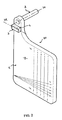
Figure 2 is a perspective three quarter front view of a distance measuring device according to the invention; -
Figure 3 is a front view of the device ofFigure 2 ; -
Figure 4 is a top view of the device ofFigure 2 ; -
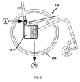
Figures 5 ,5A and 5B represent a front view of the device ofFigure 2 during the measuring operation. - In reference to
Figure 1 , one can see a schematic half cut representation of a symmetrical wheelchair of the prior art, the wheelchair being seen from its right side. As usual in wheelchairs, there is awheelchair frame 110 formed by several interconnected profiled elements defining respectively abackrest 112, a seat 114 and a legrest 116. On each side of thiswheelchair frame 110 are rotatably connected a pair ofrear wheels 120 and a pair ofcastor wheels 130. The profiled element defining the seat 114 include a series of regularly spaced assembling holes 118 constituting several assembling positions between the profiled elements defining respectively thebackrest 112 and the seat 114. By modifying this assembling position, it is possible to control the position of thebackrest 112 relative to the legrest 116. Indeed, depending on the anatomy of the user, this relative position should be shorter or longer. However, the modification of this assembling position has also an impact on the position of the vertical plane generally defined by thebackrest 112 relative to the horizontal axis of therear wheels 120. Such a relative position can be evaluated for instance by knowing the horizontal distance X existing between two horizontal parallel axis, one axis going through thelowest point 115 reached by thebackrest 112 and the other one going through thepoint 125 corresponding to the position of the free end of the rear wheel axle and aligned with the rear wheel axis. Depending on the anatomy of the user and the other features of the wheelchair, this distance X can have a bad impact on the tendency to tipping of the wheelchair. Therefore, to be sure that the modification made does not increase dangerously the tendency to tipping of the wheelchair, it is important to control that the distance X is close to a reference value Xref given by the manufacturer or the seller. In general, this reference value Xref depends on other parameters linked to the anatomy of the user. This reference value Xref can be found in a specific data table, said table indicating the distance Xref in correspondence with the measured lengths of one or several body parts of the user. Other specific data tables can also provide the user with additional reference values relative to other important length or characteristic of the wheelchair. For instance, and by reference to theFigure 1 , these tables can also determine the best value for the length RH of thebackrest 112, the length ST for the seat 114, the length UL for the legrest 116, or for the distance SHh between thelowest point 115 of thebackrest 112 and the ground or the distance SHv between the highest point of the legrest 116 and the ground. It is also possible to know the best inclination angle RW between thebackrest 112 and the seat 114. - After determining the best value for X, one needs to measure with a great precision the current value X. However, it is not easy to measure the horizontal distance X between the horizontal axis going through the
point 115 and the horizontal axis going through thepoint 125 because these two points are positioned in two parallel vertical planes separated by arear wheel 120. Therefore, if one only owns a current business measuring tool, one needs to dismantle therear wheel 120 to position said tool without being hindered by the spokes of the wheel. To prevent such a dismantling and permit an easy measuring operation, the invention proposes a new measuring tool as viewed inFigures 2 to 4 . After having measured the current distance X by using this new measuring tool, one can compare this value with the reference value Xref and, if X is different from Xref, adapt thewheelchair frame 110 in order to modify X and reach the value Xref for X. This can be done for instance by increasing or reducing the length ST of the seat 114 as mentioned above. Of course, this measuring tool can also be used for measuring the distance X on an already used wheelchair when one wants to know the best value for X. - Referring to
Figures 2 to 4 , there is shown ameasuring tool 10 according to the invention. This tool comprises atransparent support 1 defining a plane P on at least one of its side. This support is preferably made in a glass or plastic material. In the embodiment ofFigure 2 , the support defines approximately a rectangular form, but other forms can be used without departing from the invention. The plane surface P of thetool 10 bears at its top left corner aspirit level 3. Thespirit level 3 comprises avial 4, which encloses a bubble ofair 5 inside a liquid, and two marking lines 6 and 6', between which the bubble ofair 5 is centered when thespirit level 3 is level (seeFigure 3 ). In this situation, the direction Dh defined by thespirit level 3, corresponding to the longitudinal axis of the ellipsoidal bubble ofair 5, is approximately horizontal (seefigure 4 ). - To position precisely the
tool 10 during the measuring operation, thesupport 1 bears atubular rod 8 fixed at its top left corner and extending in a direction Dt orthogonal to the plane P, said direction Dt corresponding to the axis of the tube formed by therod 8. In a preferential embodiment of the invention, it could be advantageous that the length I of therod 8 is sufficient to reach thefirst point 115 when thesupport 1 is positioned in front of and next to thesecond point 125, and, in particular, is bigger than the width of therear wheel 120. - The
support 1 bears also in the plane P a series of parallel marking lines 2a to 2e, said lines extending in a direction perpendicular to the direction Dh and each marking line 2a to 2e holding a number, respectively 5 to 1. The scale formed by the combination of the lines 2a to 2e is adapted for measuring a distance. Optionally, as seen onFigures 2 and3 , it is also possible to add additional marking lines 7a to 7e in order to measure the inclination angle RW mentioned above. - In reference to
Figures 5 ,5A and 5B , one can see the different steps permitting to measure the horizontal distance X by using thetool 10. - In a first step, corresponding to the detail A of
Figure 5 and best viewed onFigure 5A , thetool 10 is positioned in front of therear wheel 120 of thewheelchair 100. Then, therod 8 of thetool 10 is aligned with thefirst point 115 and thespirit level 3 is level. In this position, the plane P is normally orthogonal to the axle of therear wheel 120. - In a second step, corresponding to the detail B of
Figure 5 and best viewed on theFigure 5B , one can see through thetransparent support 1 of thetool 10 the position of thesecond point 125. The position of thissecond point 125 is normally situated in front of one marking line 2a to 2e or between two successive marking lines 2a to 2e. The number(s) held by this (or these) marking line(s) indicates a corresponding horizontal distance X in a unit known by the user.
Claims (7)
- Device (10) for measuring the horizontal distance separating two horizontal parallel axis of a wheelchair (100), comprising:- a spirit level (3) defining a direction Dh, said direction Dh being horizontal when the spirit level is level,- a transparent support (1) defining a plane P on one of its sides and bearing on the said side a plurality of parallel marking lines (2a-2f), said lines extending in a direction perpendicular to the direction Dh and defining a scale,- a positioning element (8) attached to the transparent support (1) and extending in a direction Dt orthogonal to the plane P,characterised in that the positioning element (8) is positioned such that when the direction Dt is aligned with the lowest position of the backrest of said wheelchair, the rear wheel axle of the wheelchair projects onto said scale.
- Device (10) according to claim 1 wherein the positioning element (8) has a tubular form.
- Device (10) according to claim 2, wherein the positioning element (8) is a tubular rod having a length sufficient to reach said lowest position (115) of the backrest of said wheelchair (100) when said support (1) is positioned in front of and next to the position (125) of the free end of the rear wheel axle of the wheelchair.
- Method for adapting a wheelchair frame (110) to the anatomy of the user, comprising the following steps:a) measuring the length(s) of one or several body part(s) of the user;b) finding the measured length(s) in a specific data table, said table indicating a horizontal distance Xref in correspondence with this measured length(s), Xref corresponding to the best value for the distance between two horizontal parallel axis of the wheelchair (100) in view of the measured length(s);c) measuring the existing distance X between said axis of the wheelchair (100) by using the device (10) defined in one of the preceding claims;d) comparing X and Xref;e) if X is different from Xref then adapting the wheelchair frame (110) in order to modify X and reach the value Xref for X.
- Method according to claim 4, wherein one axis goes through the point (125) corresponding to the position of the free end of the rear wheel axle of the wheelchair (100).
- Method according to claim 4 or claim 5, wherein one axis goes through the lowest point (115) reached by the backrest (112) of the wheelchair (100).
- Method according to one of the claims 4 to 6, wherein, in step e), the adaptation of the wheelchair frame (110) corresponds to the modification of the position of one profiled element defining the seat (114) of the wheelchair (100).
Priority Applications (4)
| Application Number | Priority Date | Filing Date | Title |
|---|---|---|---|
| ES09163518T ES2384424T3 (en) | 2009-06-23 | 2009-06-23 | Distance measuring device |
| PT09163518T PT2267406E (en) | 2009-06-23 | 2009-06-23 | Distance measuring device |
| AT09163518T ATE554365T1 (en) | 2009-06-23 | 2009-06-23 | DEVICE FOR DISTANCE MEASUREMENT |
| EP09163518A EP2267406B1 (en) | 2009-06-23 | 2009-06-23 | Distance measuring device |
Applications Claiming Priority (1)
| Application Number | Priority Date | Filing Date | Title |
|---|---|---|---|
| EP09163518A EP2267406B1 (en) | 2009-06-23 | 2009-06-23 | Distance measuring device |
Publications (2)
| Publication Number | Publication Date |
|---|---|
| EP2267406A1 EP2267406A1 (en) | 2010-12-29 |
| EP2267406B1 true EP2267406B1 (en) | 2012-04-18 |
Family
ID=41226399
Family Applications (1)
| Application Number | Title | Priority Date | Filing Date |
|---|---|---|---|
| EP09163518A Not-in-force EP2267406B1 (en) | 2009-06-23 | 2009-06-23 | Distance measuring device |
Country Status (4)
| Country | Link |
|---|---|
| EP (1) | EP2267406B1 (en) |
| AT (1) | ATE554365T1 (en) |
| ES (1) | ES2384424T3 (en) |
| PT (1) | PT2267406E (en) |
Families Citing this family (2)
| Publication number | Priority date | Publication date | Assignee | Title |
|---|---|---|---|---|
| CN102954779B (en) * | 2011-08-30 | 2015-08-26 | 昆山市创新科技检测仪器有限公司 | A kind of appearance test desk of wheelchair |
| US10775146B1 (en) | 2018-09-25 | 2020-09-15 | David Moss | Distance measurement device |
Family Cites Families (9)
| Publication number | Priority date | Publication date | Assignee | Title |
|---|---|---|---|---|
| US1509451A (en) * | 1923-02-24 | 1924-09-23 | Fred D Tamplin | Measuring instrument |
| US2728989A (en) * | 1954-02-25 | 1956-01-03 | Carl J Laggren | Combination tool |
| US3852889A (en) * | 1970-05-20 | 1974-12-10 | T Atkins | Device for making perspective drawings |
| US4693011A (en) * | 1986-07-24 | 1987-09-15 | Strayham Stephen G | Apparatus for establishing angles of objects |
| US5463817A (en) | 1993-08-11 | 1995-11-07 | Leeds; Richard A. | Picture frame leveling device |
| US5361504A (en) * | 1993-08-11 | 1994-11-08 | Huang Hung C | Universal guide for electrical hand drill |
| GB9412544D0 (en) * | 1994-06-22 | 1994-08-10 | Davies Roy | Wallpapering aid |
| US6305093B1 (en) * | 1999-09-15 | 2001-10-23 | Penelope E. Venola | Hanger tool to facilitate centering and hanging of a component |
| US6467179B1 (en) | 2000-05-13 | 2002-10-22 | Sigrid Hammer Wolf | Measuring and drafting tool |
-
2009
- 2009-06-23 ES ES09163518T patent/ES2384424T3/en active Active
- 2009-06-23 PT PT09163518T patent/PT2267406E/en unknown
- 2009-06-23 EP EP09163518A patent/EP2267406B1/en not_active Not-in-force
- 2009-06-23 AT AT09163518T patent/ATE554365T1/en active
Also Published As
| Publication number | Publication date |
|---|---|
| EP2267406A1 (en) | 2010-12-29 |
| ES2384424T3 (en) | 2012-07-04 |
| PT2267406E (en) | 2012-06-18 |
| ATE554365T1 (en) | 2012-05-15 |
Similar Documents
| Publication | Publication Date | Title |
|---|---|---|
| US7178765B2 (en) | Computer supporter | |
| US6488157B2 (en) | Stand for supporting a motorcycle | |
| US5471754A (en) | Kit and method of using kit to align wheels of vehicle | |
| US7325816B2 (en) | Motorcycle dolly | |
| US5211376A (en) | Motorcycle jack | |
| US20020121754A1 (en) | Scooter with adjustable seat assembly | |
| US11160702B2 (en) | Rigid frame wheelchair | |
| US7736282B1 (en) | Bike trainer | |
| US11534675B2 (en) | Auto-balacing transportation device with stable platform pivot axes | |
| US9297648B2 (en) | Vehicle wheel alignment technology | |
| US20070096069A1 (en) | Motorcycle rear stand | |
| EP3063055A1 (en) | Bicycle stand and method of use | |
| EP2267406A1 (en) | Distance measuring device | |
| US6976385B2 (en) | Lateral wheel balancing apparatuses and methods for lateral wheel balancing | |
| CN101099706A (en) | wheelchair | |
| US7152333B1 (en) | Simple inspection device for wheel alignment | |
| JP6278514B2 (en) | Weight scale | |
| CN222068120U (en) | Adjustable base | |
| JP2003334215A (en) | Wheelchair frame and wheelchair using the frame | |
| US20090051134A1 (en) | Support stand for an inline two wheeled vehicle | |
| CN114199113B (en) | Four-wheel alignment frame | |
| CN212963168U (en) | Four-wheel positioning frame | |
| US2715033A (en) | Bicycle stabilizer | |
| CN104058028A (en) | Bicycle Stand | |
| CN212963157U (en) | Inclination angle measuring device |
Legal Events
| Date | Code | Title | Description |
|---|---|---|---|
| PUAI | Public reference made under article 153(3) epc to a published international application that has entered the european phase |
Free format text: ORIGINAL CODE: 0009012 |
|
| AK | Designated contracting states |
Kind code of ref document: A1 Designated state(s): AT BE BG CH CY CZ DE DK EE ES FI FR GB GR HR HU IE IS IT LI LT LU LV MC MK MT NL NO PL PT RO SE SI SK TR |
|
| AX | Request for extension of the european patent |
Extension state: AL BA RS |
|
| 17P | Request for examination filed |
Effective date: 20110617 |
|
| 17Q | First examination report despatched |
Effective date: 20110719 |
|
| GRAP | Despatch of communication of intention to grant a patent |
Free format text: ORIGINAL CODE: EPIDOSNIGR1 |
|
| GRAS | Grant fee paid |
Free format text: ORIGINAL CODE: EPIDOSNIGR3 |
|
| GRAA | (expected) grant |
Free format text: ORIGINAL CODE: 0009210 |
|
| AK | Designated contracting states |
Kind code of ref document: B1 Designated state(s): AT BE BG CH CY CZ DE DK EE ES FI FR GB GR HR HU IE IS IT LI LT LU LV MC MK MT NL NO PL PT RO SE SI SK TR |
|
| REG | Reference to a national code |
Ref country code: GB Ref legal event code: FG4D |
|
| REG | Reference to a national code |
Ref country code: CH Ref legal event code: EP |
|
| REG | Reference to a national code |
Ref country code: IE Ref legal event code: FG4D |
|
| REG | Reference to a national code |
Ref country code: AT Ref legal event code: REF Ref document number: 554365 Country of ref document: AT Kind code of ref document: T Effective date: 20120515 Ref country code: CH Ref legal event code: NV Representative=s name: ABREMA AGENCE BREVET ET MARQUES, GANGUILLET |
|
| REG | Reference to a national code |
Ref country code: DE Ref legal event code: R096 Ref document number: 602009006352 Country of ref document: DE Effective date: 20120614 |
|
| REG | Reference to a national code |
Ref country code: PT Ref legal event code: SC4A Free format text: AVAILABILITY OF NATIONAL TRANSLATION Effective date: 20120606 |
|
| REG | Reference to a national code |
Ref country code: NL Ref legal event code: T3 |
|
| REG | Reference to a national code |
Ref country code: ES Ref legal event code: FG2A Ref document number: 2384424 Country of ref document: ES Kind code of ref document: T3 Effective date: 20120704 |
|
| REG | Reference to a national code |
Ref country code: AT Ref legal event code: MK05 Ref document number: 554365 Country of ref document: AT Kind code of ref document: T Effective date: 20120418 |
|
| LTIE | Lt: invalidation of european patent or patent extension |
Effective date: 20120418 |
|
| PG25 | Lapsed in a contracting state [announced via postgrant information from national office to epo] |
Ref country code: LT Free format text: LAPSE BECAUSE OF FAILURE TO SUBMIT A TRANSLATION OF THE DESCRIPTION OR TO PAY THE FEE WITHIN THE PRESCRIBED TIME-LIMIT Effective date: 20120418 Ref country code: SE Free format text: LAPSE BECAUSE OF FAILURE TO SUBMIT A TRANSLATION OF THE DESCRIPTION OR TO PAY THE FEE WITHIN THE PRESCRIBED TIME-LIMIT Effective date: 20120418 Ref country code: CY Free format text: LAPSE BECAUSE OF FAILURE TO SUBMIT A TRANSLATION OF THE DESCRIPTION OR TO PAY THE FEE WITHIN THE PRESCRIBED TIME-LIMIT Effective date: 20120418 Ref country code: FI Free format text: LAPSE BECAUSE OF FAILURE TO SUBMIT A TRANSLATION OF THE DESCRIPTION OR TO PAY THE FEE WITHIN THE PRESCRIBED TIME-LIMIT Effective date: 20120418 Ref country code: PL Free format text: LAPSE BECAUSE OF FAILURE TO SUBMIT A TRANSLATION OF THE DESCRIPTION OR TO PAY THE FEE WITHIN THE PRESCRIBED TIME-LIMIT Effective date: 20120418 Ref country code: NO Free format text: LAPSE BECAUSE OF FAILURE TO SUBMIT A TRANSLATION OF THE DESCRIPTION OR TO PAY THE FEE WITHIN THE PRESCRIBED TIME-LIMIT Effective date: 20120718 Ref country code: IS Free format text: LAPSE BECAUSE OF FAILURE TO SUBMIT A TRANSLATION OF THE DESCRIPTION OR TO PAY THE FEE WITHIN THE PRESCRIBED TIME-LIMIT Effective date: 20120818 |
|
| PG25 | Lapsed in a contracting state [announced via postgrant information from national office to epo] |
Ref country code: SI Free format text: LAPSE BECAUSE OF FAILURE TO SUBMIT A TRANSLATION OF THE DESCRIPTION OR TO PAY THE FEE WITHIN THE PRESCRIBED TIME-LIMIT Effective date: 20120418 Ref country code: GR Free format text: LAPSE BECAUSE OF FAILURE TO SUBMIT A TRANSLATION OF THE DESCRIPTION OR TO PAY THE FEE WITHIN THE PRESCRIBED TIME-LIMIT Effective date: 20120719 Ref country code: HR Free format text: LAPSE BECAUSE OF FAILURE TO SUBMIT A TRANSLATION OF THE DESCRIPTION OR TO PAY THE FEE WITHIN THE PRESCRIBED TIME-LIMIT Effective date: 20120418 Ref country code: LV Free format text: LAPSE BECAUSE OF FAILURE TO SUBMIT A TRANSLATION OF THE DESCRIPTION OR TO PAY THE FEE WITHIN THE PRESCRIBED TIME-LIMIT Effective date: 20120418 |
|
| PG25 | Lapsed in a contracting state [announced via postgrant information from national office to epo] |
Ref country code: CZ Free format text: LAPSE BECAUSE OF FAILURE TO SUBMIT A TRANSLATION OF THE DESCRIPTION OR TO PAY THE FEE WITHIN THE PRESCRIBED TIME-LIMIT Effective date: 20120418 Ref country code: SK Free format text: LAPSE BECAUSE OF FAILURE TO SUBMIT A TRANSLATION OF THE DESCRIPTION OR TO PAY THE FEE WITHIN THE PRESCRIBED TIME-LIMIT Effective date: 20120418 Ref country code: MC Free format text: LAPSE BECAUSE OF NON-PAYMENT OF DUE FEES Effective date: 20120630 Ref country code: RO Free format text: LAPSE BECAUSE OF FAILURE TO SUBMIT A TRANSLATION OF THE DESCRIPTION OR TO PAY THE FEE WITHIN THE PRESCRIBED TIME-LIMIT Effective date: 20120418 Ref country code: EE Free format text: LAPSE BECAUSE OF FAILURE TO SUBMIT A TRANSLATION OF THE DESCRIPTION OR TO PAY THE FEE WITHIN THE PRESCRIBED TIME-LIMIT Effective date: 20120418 Ref country code: DK Free format text: LAPSE BECAUSE OF FAILURE TO SUBMIT A TRANSLATION OF THE DESCRIPTION OR TO PAY THE FEE WITHIN THE PRESCRIBED TIME-LIMIT Effective date: 20120418 Ref country code: AT Free format text: LAPSE BECAUSE OF FAILURE TO SUBMIT A TRANSLATION OF THE DESCRIPTION OR TO PAY THE FEE WITHIN THE PRESCRIBED TIME-LIMIT Effective date: 20120418 |
|
| PLBE | No opposition filed within time limit |
Free format text: ORIGINAL CODE: 0009261 |
|
| STAA | Information on the status of an ep patent application or granted ep patent |
Free format text: STATUS: NO OPPOSITION FILED WITHIN TIME LIMIT |
|
| PG25 | Lapsed in a contracting state [announced via postgrant information from national office to epo] |
Ref country code: MK Free format text: LAPSE BECAUSE OF FAILURE TO SUBMIT A TRANSLATION OF THE DESCRIPTION OR TO PAY THE FEE WITHIN THE PRESCRIBED TIME-LIMIT Effective date: 20120418 |
|
| 26N | No opposition filed |
Effective date: 20130121 |
|
| REG | Reference to a national code |
Ref country code: IE Ref legal event code: MM4A |
|
| PG25 | Lapsed in a contracting state [announced via postgrant information from national office to epo] |
Ref country code: IE Free format text: LAPSE BECAUSE OF NON-PAYMENT OF DUE FEES Effective date: 20120623 |
|
| REG | Reference to a national code |
Ref country code: DE Ref legal event code: R097 Ref document number: 602009006352 Country of ref document: DE Effective date: 20130121 |
|
| PG25 | Lapsed in a contracting state [announced via postgrant information from national office to epo] |
Ref country code: MT Free format text: LAPSE BECAUSE OF FAILURE TO SUBMIT A TRANSLATION OF THE DESCRIPTION OR TO PAY THE FEE WITHIN THE PRESCRIBED TIME-LIMIT Effective date: 20120418 Ref country code: BG Free format text: LAPSE BECAUSE OF FAILURE TO SUBMIT A TRANSLATION OF THE DESCRIPTION OR TO PAY THE FEE WITHIN THE PRESCRIBED TIME-LIMIT Effective date: 20120718 |
|
| PG25 | Lapsed in a contracting state [announced via postgrant information from national office to epo] |
Ref country code: TR Free format text: LAPSE BECAUSE OF FAILURE TO SUBMIT A TRANSLATION OF THE DESCRIPTION OR TO PAY THE FEE WITHIN THE PRESCRIBED TIME-LIMIT Effective date: 20120418 |
|
| PG25 | Lapsed in a contracting state [announced via postgrant information from national office to epo] |
Ref country code: LU Free format text: LAPSE BECAUSE OF NON-PAYMENT OF DUE FEES Effective date: 20120623 |
|
| PG25 | Lapsed in a contracting state [announced via postgrant information from national office to epo] |
Ref country code: HU Free format text: LAPSE BECAUSE OF FAILURE TO SUBMIT A TRANSLATION OF THE DESCRIPTION OR TO PAY THE FEE WITHIN THE PRESCRIBED TIME-LIMIT Effective date: 20090623 |
|
| REG | Reference to a national code |
Ref country code: FR Ref legal event code: PLFP Year of fee payment: 8 |
|
| PGFP | Annual fee paid to national office [announced via postgrant information from national office to epo] |
Ref country code: ES Payment date: 20160614 Year of fee payment: 8 Ref country code: GB Payment date: 20160621 Year of fee payment: 8 Ref country code: DE Payment date: 20160621 Year of fee payment: 8 |
|
| PGFP | Annual fee paid to national office [announced via postgrant information from national office to epo] |
Ref country code: NL Payment date: 20160620 Year of fee payment: 8 Ref country code: FR Payment date: 20160627 Year of fee payment: 8 Ref country code: BE Payment date: 20160620 Year of fee payment: 8 Ref country code: PT Payment date: 20160620 Year of fee payment: 8 |
|
| PGFP | Annual fee paid to national office [announced via postgrant information from national office to epo] |
Ref country code: IT Payment date: 20160628 Year of fee payment: 8 Ref country code: CH Payment date: 20160714 Year of fee payment: 8 |
|
| REG | Reference to a national code |
Ref country code: DE Ref legal event code: R119 Ref document number: 602009006352 Country of ref document: DE |
|
| REG | Reference to a national code |
Ref country code: CH Ref legal event code: PL |
|
| REG | Reference to a national code |
Ref country code: NL Ref legal event code: MM Effective date: 20170701 |
|
| GBPC | Gb: european patent ceased through non-payment of renewal fee |
Effective date: 20170623 |
|
| PG25 | Lapsed in a contracting state [announced via postgrant information from national office to epo] |
Ref country code: PT Free format text: LAPSE BECAUSE OF NON-PAYMENT OF DUE FEES Effective date: 20171227 |
|
| PG25 | Lapsed in a contracting state [announced via postgrant information from national office to epo] |
Ref country code: NL Free format text: LAPSE BECAUSE OF NON-PAYMENT OF DUE FEES Effective date: 20170701 |
|
| REG | Reference to a national code |
Ref country code: FR Ref legal event code: ST Effective date: 20180228 |
|
| PG25 | Lapsed in a contracting state [announced via postgrant information from national office to epo] |
Ref country code: CH Free format text: LAPSE BECAUSE OF NON-PAYMENT OF DUE FEES Effective date: 20170630 Ref country code: DE Free format text: LAPSE BECAUSE OF NON-PAYMENT OF DUE FEES Effective date: 20180103 Ref country code: GB Free format text: LAPSE BECAUSE OF NON-PAYMENT OF DUE FEES Effective date: 20170623 Ref country code: LI Free format text: LAPSE BECAUSE OF NON-PAYMENT OF DUE FEES Effective date: 20170630 |
|
| REG | Reference to a national code |
Ref country code: BE Ref legal event code: MM Effective date: 20170630 |
|
| PG25 | Lapsed in a contracting state [announced via postgrant information from national office to epo] |
Ref country code: IT Free format text: LAPSE BECAUSE OF NON-PAYMENT OF DUE FEES Effective date: 20170623 Ref country code: FR Free format text: LAPSE BECAUSE OF NON-PAYMENT OF DUE FEES Effective date: 20170630 |
|
| PG25 | Lapsed in a contracting state [announced via postgrant information from national office to epo] |
Ref country code: BE Free format text: LAPSE BECAUSE OF NON-PAYMENT OF DUE FEES Effective date: 20170630 |
|
| REG | Reference to a national code |
Ref country code: ES Ref legal event code: FD2A Effective date: 20181107 |
|
| PG25 | Lapsed in a contracting state [announced via postgrant information from national office to epo] |
Ref country code: ES Free format text: LAPSE BECAUSE OF NON-PAYMENT OF DUE FEES Effective date: 20170624 |