EP2267366B1 - Method and apparatus of controlling combustion in oxyfuel combustion boiler - Google Patents
Method and apparatus of controlling combustion in oxyfuel combustion boiler Download PDFInfo
- Publication number
- EP2267366B1 EP2267366B1 EP08720359.2A EP08720359A EP2267366B1 EP 2267366 B1 EP2267366 B1 EP 2267366B1 EP 08720359 A EP08720359 A EP 08720359A EP 2267366 B1 EP2267366 B1 EP 2267366B1
- Authority
- EP
- European Patent Office
- Prior art keywords
- density
- oxygen
- exhaust gas
- boiler
- flow rate
- Prior art date
- Legal status (The legal status is an assumption and is not a legal conclusion. Google has not performed a legal analysis and makes no representation as to the accuracy of the status listed.)
- Active
Links
Images


Classifications
-
- F—MECHANICAL ENGINEERING; LIGHTING; HEATING; WEAPONS; BLASTING
- F23—COMBUSTION APPARATUS; COMBUSTION PROCESSES
- F23C—METHODS OR APPARATUS FOR COMBUSTION USING FLUID FUEL OR SOLID FUEL SUSPENDED IN A CARRIER GAS OR AIR
- F23C9/00—Combustion apparatus characterised by arrangements for returning combustion products or flue gases to the combustion chamber
-
- F—MECHANICAL ENGINEERING; LIGHTING; HEATING; WEAPONS; BLASTING
- F22—STEAM GENERATION
- F22B—METHODS OF STEAM GENERATION; STEAM BOILERS
- F22B35/00—Control systems for steam boilers
- F22B35/002—Control by recirculating flue gases
-
- F—MECHANICAL ENGINEERING; LIGHTING; HEATING; WEAPONS; BLASTING
- F23—COMBUSTION APPARATUS; COMBUSTION PROCESSES
- F23L—SUPPLYING AIR OR NON-COMBUSTIBLE LIQUIDS OR GASES TO COMBUSTION APPARATUS IN GENERAL ; VALVES OR DAMPERS SPECIALLY ADAPTED FOR CONTROLLING AIR SUPPLY OR DRAUGHT IN COMBUSTION APPARATUS; INDUCING DRAUGHT IN COMBUSTION APPARATUS; TOPS FOR CHIMNEYS OR VENTILATING SHAFTS; TERMINALS FOR FLUES
- F23L7/00—Supplying non-combustible liquids or gases, other than air, to the fire, e.g. oxygen, steam
- F23L7/007—Supplying oxygen or oxygen-enriched air
-
- F—MECHANICAL ENGINEERING; LIGHTING; HEATING; WEAPONS; BLASTING
- F23—COMBUSTION APPARATUS; COMBUSTION PROCESSES
- F23C—METHODS OR APPARATUS FOR COMBUSTION USING FLUID FUEL OR SOLID FUEL SUSPENDED IN A CARRIER GAS OR AIR
- F23C2202/00—Fluegas recirculation
- F23C2202/50—Control of recirculation rate
-
- Y—GENERAL TAGGING OF NEW TECHNOLOGICAL DEVELOPMENTS; GENERAL TAGGING OF CROSS-SECTIONAL TECHNOLOGIES SPANNING OVER SEVERAL SECTIONS OF THE IPC; TECHNICAL SUBJECTS COVERED BY FORMER USPC CROSS-REFERENCE ART COLLECTIONS [XRACs] AND DIGESTS
- Y02—TECHNOLOGIES OR APPLICATIONS FOR MITIGATION OR ADAPTATION AGAINST CLIMATE CHANGE
- Y02E—REDUCTION OF GREENHOUSE GAS [GHG] EMISSIONS, RELATED TO ENERGY GENERATION, TRANSMISSION OR DISTRIBUTION
- Y02E20/00—Combustion technologies with mitigation potential
- Y02E20/34—Indirect CO2mitigation, i.e. by acting on non CO2directly related matters of the process, e.g. pre-heating or heat recovery
Definitions
- the present invention relates to an apparatus of controlling combustion in an oxyfuel combustion boiler.
- CO 2 carbon dioxide
- a thermal power plant appears close-up as a fixed source of discharging these substances.
- Fuel for thermal power generation may be oil, natural gas and coal, among which coal is especially anticipated to have a large future demand due to its greater potential reserves.
- Coal contains a higher percentage of carbon as compared with natural gas and oil, together with other components such as hydrogen, nitrogen and sulfur, and ash as an inorganic component. Therefore, when coal is burned in the air, most of the composition of the combustion exhaust gas is occupied by nitrogen (about 70%), with the remainder occupied by carbon dioxide CO 2 , sulfur oxide SO x , nitrogen oxide NO x , dust comprising ash and unburned coal particles, and oxygen (about 4%).
- the combustion exhaust gas is thus subjected to exhaust gas treatments such as denitration, desulfurization and dedusting so that NO x , SO x and particulates fall under their respective environmental emission standard values before the emission to the atmosphere through a stack.
- NO x occurring in the combustion exhaust gas is divided into a thermal NO x generated from oxidization of nitrogen in the air by oxygen and a fuel NO x generated as a result of oxidization of nitrogen in the fuel.
- a combustion method of lowering the flame temperature has been employed for reduction of the thermal NO x
- another combustion method of forming a fuel-excess region for deoxidizing NO x within a burner has been employed for reduction of the fuel NO x .
- a wet or dry desulfurizing device has been provided to remove SO x occurring in the combustion exhaust gas as a result of the combustion.
- EP 0081114 discloses an apparatus for controlling combustion in a boiler.
- nitrogen is a balance gas for oxygen which is a major component gas other than oxygen in the air used for combustion of pulverized coal whereas in an oxyfuel combustion boiler, carbon dioxide and steam become balance gases for oxygen since they are main component gases other than oxygen in the recirculating exhaust gas.
- the invention was made in view of the above and has its object to provide an apparatus of controlling combustion in an oxyfuel combustion boiler, ensuring a sufficient furnace heat absorption through prevention of lowering of flame temperature to thereby achieve stabilized oxyfuel combustion operations.
- the invention is directed to an apparatus of controlling combustion in an oxyfuel combustion boiler where while oxygen fed from an air separation unit is introduced into a coal burning boiler, an exhaust gas in recirculation is introduced as primary and secondary recirculating exhaust gases into a mill and the coal burning boiler, respectively, the pulverized coal pulverized by the mill being transferred by said primary recirculating exhaust gas to a burner for oxyfuel combustion with said oxygen and said secondary recirculating exhaust gas, the apparatus comprising an O 2 density monitor for sensing an O 2 density of oxygen to be introduced into the coal burning boiler, a flowmeter for sensing a flow rate of oxygen to be introduced into the coal burning boiler, an O 2 density monitor for sensing an O 2 density of the primary recirculating exhaust gas to be introduced into the mill, a flowmeter for sensing a flow rate of the primary recirculating exhaust gas to be introduced into the mill, an O 2 density monitor for sensing an O 2 density of the secondary recirculating exhaust gas to be introduced into the coal burning boiler, a flowmeter for sensing a flow rate of the
- the invention is further directed to an apparatus of controlling combustion in an oxyfuel combustion boiler where while oxygen fed from an air separation unit is introduced into a coal burning boiler, an exhaust gas in recirculation is introduced as primary and secondary recirculating exhaust gases into a mill and the coal burning boiler, respectively, the pulverized coal pulverized by the mill being transferred by said primary recirculating exhaust gas to a burner for oxyfuel combustion with said oxygen and said secondary recirculating exhaust gas, the apparatus comprising an O 2 density monitor for sensing an O 2 density of oxygen to be introduced into the coal burning boiler, a flowmeter for sensing a flow rate of oxygen to be introduced into the coal burning boiler, an O 2 density monitor for sensing an O 2 density of total recirculating exhaust gases to be introduced into the mill and the coal burning boiler, a flowmeter for sensing a flow rate of total recirculating exhaust gases to be introduced into the mill and the coal burning boiler, a flow rate regulator for regulating a flow rate of the total recirculating exhaust gases to be introduced into the mill and the coal burning boiler and
- the boiler-brought-in oxygen density falls within a range from 25 to 30%.
- an apparatus of controlling combustion in an oxyfuel combustion boiler of the invention there can be obtained an excellent effect of ensuring a sufficient furnace heat absorption through prevention of lowering of flame temperature to thereby achieve stabilized oxyfuel combustion operations.
- reference numeral 1 denotes a coal bunker for coal storage; 2, a coal feeder for feeding coal stored in the bunker 1; 3, a mill for pulverization and drying of the coal from the feeder 2; 4, a coal burning boiler; 5, a wind box fitted to the boiler 4; 6, a burner disposed in the wind box 5 for burning pulverized coal from the mill 3; 7, an exhaust gas line through which flows an exhaust gas emitted from the boiler 4; 8, an air preheater for heat exchange of the exhaust gas flowing through the exhaust gas line 7 with primary and secondary recirculating exhaust gases; 9, exhaust gas treating devices such as a desulfurizer and a dust collector for treatment of the exhaust gas passing through the air preheater 8; 10, an air separation unit for production of oxygen; 11, a forced draft fan (FDF) for forcedly sending the exhaust gas purified by the treating devices 9 as primary and secondary recirculating exhaust gases; 12, a primary recirculating exhaust gas line for leading a part of the exhaust gas
- FDF forced draft fan
- an induced draft fan disposed downstream of the exhaust gas treating devices 9 for inducedly sucking down the exhaust gas; and 21, a stack for emission to the atmosphere of the exhaust gas purified by the exhaust gas treating devices 9 and induced by the induced draft fan 20.
- an O 2 density monitor 22 and a flowmeter 23 for measuring, respectively, an O 2 density 22a and a flow rate 23a of oxygen to be directly fed to the wind box 5 of the coal burning boiler 4.
- an O 2 density monitor 24 and a flowmeter 25 for sensing, respectively, an O 2 density 24a and a flow rate 25a of the primary recirculating exhaust gas to be introduced into the mill 3.
- an O 2 density monitor 26 and a flowmeter 27 for sensing, respectively, an O 2 density 26a and a flow rate 27a of the secondary recirculating exhaust gas fed with oxygen from the oxygen feed line 17 for secondary recirculating exhaust gas.
- a flow rate regulating damper 29 acting as a flow rate regulator for regulating a flow rate of total recirculating exhaust gases to be introduced into the mill 3 and the coal burning boiler 4.
- a controller 30 is disposed for calculating a boiler-brought-in oxygen density which is an oxygen density for a total amount of gases introduced into the coal burning boiler 4 on the basis of the O 2 densities 22a, 24a and 26a measured by the O 2 density monitors 22, 24 and 26, respectively, and the flow rates 23a, 25a and 27a measured by the flowmeters 23, 25 and 27, respectively, the controller 30 outputting an opening degree control signal 29a as flow rate control signal to the flow rate regulating damper 29 such that the boiler-brought-in oxygen density falls within a predetermined range.
- any other flow rate regulator such as a damper may be used to which the flow rate control signal is outputted from the controller 30.
- the range of the boiler-brought-in oxygen density is preferably from 25 to 30% and is particularly preferably of the order of 27%. This is based on that the boiler-brought-in oxygen density satisfying the furnace heat absorption allowable range is 25 to 30% in the oxyfuel combustion environment when a furnace heat absorption allowable range is defined, from operation results in the air combustion environment, to be of the order of from 49 to 60% on the basis of the fact that furnace heat absorption of the coal burning boiler 4 becomes of the order of 52% in the case of the air oxygen density of 21%.
- the coal stored in the coal bunker 1 is fed by the coal feeder 2 to the mill 3 where coal is pulverized into pulverized coal.
- a part of the exhaust gas forcedly sent by the forced draft fan 11 from the recirculating exhaust gas line 28 is led as primary recirculating exhaust gas through the primary recirculating exhaust gas line 12 into the mill 3 via the air preheater 8 for preheating; the primary recirculating exhaust gas dries the coal fed to the mill 3 and transfers the pulverized coal produced by the mill 3 to the burner 6.
- Another part of the exhaust gas forcedly sent by the forced draft fan 11 from the recirculating exhaust gas line 28 is led as secondary recirculating exhaust gas through the secondary recirculating exhaust gas line 16, via the air preheater 8 for preheating, into the wind box 5 of the coal burning boiler 4 to which oxygen produced by the air separation unit 10 is directly fed through the oxygen feed line 18 for wind box, so that the pulverized coal is subjected to oxyfuel combustion within the coal burning boiler 4.
- An exhaust gas from the coal burning boiler 4 is introduced through the exhaust gas line 7 into the air preheater 8 where the primary and secondary recirculating exhaust gases are heated and subjected to heat recovery.
- the exhaust gas passing through the air preheater 8 goes to the exhaust gas treating devices 9 such as a desulfurizer and a dust collector for desulfurization and dust collection, with the result that the exhaust gas purified by the exhaust gas treating devices 9 is inducedly sucked by the induced draft fan 20 before the emission through the stack 21 to the atmosphere.
- the exhaust gas passing through the exhaust gas treating devices 9 is partly recirculated by the forced draft fan 11 and partly introduced into the capture device 19 for the capture of CO 2 etc. from the exhaust gas.
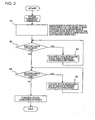
- the O 2 density 22a of oxygen to be directly fed to the wind box 5 of the coal burning boiler 4 is sensed by the O 2 density monitor 22; the flow rate 23a of oxygen to be directly fed to the wind box 5 of the coal burning boiler 4 is sensed by the flowmeter 23; the O 2 density 24a of the primary recirculating exhaust gas to be introduced into the mill 3 is sensed by the O 2 density monitor 24; the flow rate 25a of the primary recirculating exhaust gas to be introduced into the mill 3 is sensed by the flowmeter 25; the O 2 density 26a of the secondary recirculating exhaust gas fed with oxygen from the oxygen feed line 17 for secondary recirculating exhaust gas is sensed by the O 2 density monitor 26; the flow rate 27a of the secondary recirculating exhaust gas fed with oxygen from the oxygen feed line 17 for secondary recirculating exhaust gas is sensed by the flowmeter 27; and the boiler-brought-in oxygen density which is an oxygen density to the total amount of gases introduced into the coal burning boiler 4 is calculated by the controller 30
- step S2 of Fig. 2 It is then determined whether the boiler-brought-in oxygen density is below 25% (see step S2 of Fig. 2 ). If affirmative, i.e., if the boiler-brought-in oxygen density is below 25%, then an opening degree of the flow rate regulating damper 29 acting as the flow rate regulator is reduced in response to the opening degree control signal 29a serving as flow rate control signal outputted from the controller 30 to thereby reduce a flow rate of the total recirculating exhaust gases flowing through the recirculating exhaust gas line 28 (see step S3 of Fig. 2 ).
- step S4 of Fig. 2 it is determined whether the boiler-brought-in oxygen density is over 30% (see step S4 of Fig. 2 ). If affirmative, i.e., if the boiler-brought-in oxygen density is over 30%, then the opening degree of the flow rate regulating damper 29 acting as flow rate regulator is increased in response to the opening degree control signal 29a serving as flow rate control signal outputted from the controller 30 to thereby increase the flow rate of the total recirculating exhaust gases flowing through the recirculating exhaust gas line 28 (see step S5 of Fig. 2 ).
- the boiler-brought-in oxygen density falls within a predetermined range (25 to 30%) to prevent the flame temperature from lowering, to obtain a sufficient furnace heat absorption lying within a range of the order of ⁇ 5% of the furnace heat absorption obtained from the operation results in the air combustion environment, thereby achieving stabilized oxyfuel combustion operations.
- the sufficient furnace heat absorption is thus obtained through prevention of lowering of the flame temperature, enabling the oxyfuel combustion operations to be performed in a stable manner.
- Fig. 4 shows a further embodiment of the invention where parts similar to those in Fig. 1 are represented by the same reference numerals.
- the further embodiment is similar in fundamental configuration to that in Fig. 1 and is characteristic, as shown in Fig. 4 , in that an O 2 density monitor 31 and a flowmeter 32 for sensing, respectively, an O 2 density 31a and a flow rate 32a of oxygen to be introduced into the coal burning boiler 4 are incorporated in the oxygen feed line from the air separation unit 10 upstream of a branch point between the oxygen feed line 17 for secondary recirculating exhaust gas and the oxygen feed line 18 for wind box, incorporated in the recirculating exhaust gas line 28 being an O 2 density monitor 33, a flowmeter 34 and a flow rate regulating damper 29 acting as flow rate regulator, respectively, for sensing an O 2 density 33a and a flow rate 34a of and for regulating the flow rate of the total recirculating exhaust gases to be introduced into the mill 3 and the coal burning boiler 4, a boiler-brought-in oxygen density of oxygen introduced into the coal
- the O 2 density 31a and the flow rate 32a of oxygen introduced into the coal burning boiler 4 are sensed by the O 2 density monitor 31 and the flowmeter 32, respectively; the O 2 density 33a and the flow rate 34a of the total recirculating exhaust gases to be introduced into the mill 3 and the coal burning boiler 4 are sensed by the O 2 density monitor 33 and the flowmeter 34, respectively.
- the boiler-brought-in oxygen density of oxygen introduced into the coal burning boiler 4 is calculated in the controller 30 on the basis of the O 2 densities 31a and 33a sensed by the O 2 density monitors 31 and 33, respectively, and the flow rates 32a and 34a sensed by the flowmeters 32 and 34, respectively (see step S1 of Fig.
- step S2 of Fig. 2 It is determined whether the boiler-brought-in oxygen density is below 25% (see step S2 of Fig. 2 ); if affirmative, i.e., if the boiler-brought-in oxygen density is below 25%, the opening degree of the flow rate regulating damper 29 acting as flow rate regulator is reduced in response to the opening degree control signal 29a serving as flow rate control signal outputted from the controller 30 to thereby reduce the flow rate of the total recirculating exhaust gases flowing through the recirculating exhaust gas line 28 (see step S3 of Fig. 2 ); if negative, i.e., if the boiler-brought-in oxygen density is not below 25%, it is determined whether the boiler-brought-in oxygen density is over 30% (see step S4 of Fig.
- the opening degree of the flow rate regulating damper 29 acting as flow rate regulator is increased in response to the opening degree control signal 29a serving as flow rate control signal outputted from the controller 30 to thereby increase the flow rate of the total recirculating exhaust gases flowing through the recirculating exhaust gas line 28 (see step S5 of Fig. 2 ), whereupon the boiler-brought-in oxygen density falls within the predetermined range (25 to 30%) to prevent the flame temperature from lowering, to obtain a sufficient furnace heat absorption lying within a range of the order of ⁇ 5% of the furnace heat absorption obtained from the operation results in the air combustion environment, thereby achieving stabilized oxyfuel combustion operations.
- Fig. 4 embodiment also ensures a sufficient furnace heat absorption through prevention of lowering of the flame temperature, enabling the oxyfuel combustion operations to be performed in a stable manner.
- Fig. 4 embodiment employs a less number of O 2 density monitors and flowmeters as compared with the Fig. 1 embodiment.
Priority Applications (1)
| Application Number | Priority Date | Filing Date | Title |
|---|---|---|---|
| PL08720359T PL2267366T3 (pl) | 2008-03-06 | 2008-03-06 | Sposób i urządzenie do sterowania spalaniem w kotle do spalania tlenowo-paliwowego |
Applications Claiming Priority (1)
| Application Number | Priority Date | Filing Date | Title |
|---|---|---|---|
| PCT/JP2008/000473 WO2009110035A1 (ja) | 2008-03-06 | 2008-03-06 | 酸素燃焼ボイラの燃焼制御方法及び装置 |
Publications (3)
| Publication Number | Publication Date |
|---|---|
| EP2267366A1 EP2267366A1 (en) | 2010-12-29 |
| EP2267366A4 EP2267366A4 (en) | 2012-06-06 |
| EP2267366B1 true EP2267366B1 (en) | 2015-06-03 |
Family
ID=41055617
Family Applications (1)
| Application Number | Title | Priority Date | Filing Date |
|---|---|---|---|
| EP08720359.2A Active EP2267366B1 (en) | 2008-03-06 | 2008-03-06 | Method and apparatus of controlling combustion in oxyfuel combustion boiler |
Country Status (9)
| Country | Link |
|---|---|
| US (1) | US20110104624A1 (zh) |
| EP (1) | EP2267366B1 (zh) |
| JP (1) | JP5107419B2 (zh) |
| KR (1) | KR101249713B1 (zh) |
| CN (1) | CN102084184B (zh) |
| AU (1) | AU2008352211B2 (zh) |
| ES (1) | ES2544678T3 (zh) |
| PL (1) | PL2267366T3 (zh) |
| WO (1) | WO2009110035A1 (zh) |
Families Citing this family (10)
| Publication number | Priority date | Publication date | Assignee | Title |
|---|---|---|---|---|
| CN102084184B (zh) * | 2008-03-06 | 2013-07-17 | 株式会社Ihi | 氧气燃烧锅炉的燃烧控制方法及装置 |
| US8453585B2 (en) * | 2008-04-14 | 2013-06-04 | Babcock & Wilcox Power Generation Group, Inc. | Oxy-combustion coal fired boiler and method of transitioning between air and oxygen firing |
| US8789479B2 (en) * | 2009-11-09 | 2014-07-29 | Ihi Corporation | Oxygen mixer for oxygen combustion boiler |
| JP5357714B2 (ja) * | 2009-11-20 | 2013-12-04 | 三菱重工業株式会社 | ボイラ装置 |
| US8640656B1 (en) * | 2010-02-27 | 2014-02-04 | Woody Vouth Vann | Self-sustaining boiler system |
| JP5789146B2 (ja) * | 2011-07-13 | 2015-10-07 | 株式会社神戸製鋼所 | 微粉炭焚きボイラ設備の運転方法および微粉炭焚きボイラ設備 |
| JP5979668B2 (ja) * | 2012-09-28 | 2016-08-24 | 三菱日立パワーシステムズ株式会社 | 固体燃料バーナを備えた燃焼装置とその運転方法 |
| CN103398397A (zh) * | 2013-07-24 | 2013-11-20 | 张蕊 | 一种锅炉燃烧系统及利用该系统燃烧的方法 |
| CN105042632A (zh) * | 2015-07-27 | 2015-11-11 | 中国神华能源股份有限公司 | 一种富氧燃烧系统锅炉安全保护控制装置和方法 |
| CN105042630B (zh) * | 2015-07-27 | 2017-10-17 | 中国神华能源股份有限公司 | 富氧燃烧系统供氧控制装置和方法 |
Citations (3)
| Publication number | Priority date | Publication date | Assignee | Title |
|---|---|---|---|---|
| JP2001115204A (ja) * | 1999-10-15 | 2001-04-24 | Mitsubishi Heavy Ind Ltd | 還元鉄の製造装置及び炉内温度の測定装置 |
| EP1186675A1 (en) * | 2000-09-07 | 2002-03-13 | Daido Tokushuko Kabushiki Kaisha | Apparatus for controlling introduced air in metal oxide reducing furnace |
| EP2267366A1 (en) * | 2008-03-06 | 2010-12-29 | IHI Corporation | Method of controlling combustion in oxygen combustion boiler and apparatus therefor |
Family Cites Families (15)
| Publication number | Priority date | Publication date | Assignee | Title |
|---|---|---|---|---|
| US4177950A (en) * | 1978-02-16 | 1979-12-11 | Westinghouse Electric Corp. | Control for a power plant coal mill pulverizer having feedforward damper positioning |
| JPS553521A (en) * | 1978-06-21 | 1980-01-11 | Mitsubishi Heavy Ind Ltd | Combustion device for industrial ceramic furnace |
| US4411204A (en) * | 1981-12-07 | 1983-10-25 | Combustion Engineering, Inc. | Method of firing a pulverized fuel-fired steam generator |
| JPS5984022A (ja) * | 1982-11-08 | 1984-05-15 | Ebara Corp | 都市ごみ焼却設備の運転方法 |
| JP3068888B2 (ja) | 1991-05-28 | 2000-07-24 | 株式会社日立製作所 | 燃焼装置及びその運転方法 |
| US6532881B2 (en) * | 1999-06-10 | 2003-03-18 | L'air Liquide - Societe' Anonyme A' Directoire Et Conseil De Surveillance Pour L'etude Et L'exploitation De Procedes Georges Claude | Method for operating a boiler using oxygen-enriched oxidants |
| JP4161515B2 (ja) * | 2000-05-30 | 2008-10-08 | 株式会社Ihi | 酸素燃焼ボイラ設備の排ガス酸素濃度制御方法及び装置 |
| US6935251B2 (en) * | 2002-02-15 | 2005-08-30 | American Air Liquide, Inc. | Steam-generating combustion system and method for emission control using oxygen enhancement |
| US8246343B2 (en) * | 2003-01-21 | 2012-08-21 | L'air Liquide Societe Anonyme Pour L'etude Et L'exploitation Des Procedes Georges Claude | Device and method for efficient mixing of two streams |
| US7261046B1 (en) * | 2003-06-10 | 2007-08-28 | Aptech Engineering Services, Inc. | System and method of reducing pulverizer flammability hazard and boiler nitrous oxide output |
| US6843185B1 (en) * | 2003-06-27 | 2005-01-18 | Maxon Corporation | Burner with oxygen and fuel mixing apparatus |
| DE102005009957B4 (de) * | 2005-03-04 | 2007-02-01 | Martin GmbH für Umwelt- und Energietechnik | Verfahren zum Verbrennen von Brennstoffen, insbesondere Abfall |
| JP4731293B2 (ja) * | 2005-11-28 | 2011-07-20 | 電源開発株式会社 | 酸素燃焼ボイラの燃焼制御方法及び装置 |
| JP2007147161A (ja) * | 2005-11-28 | 2007-06-14 | Electric Power Dev Co Ltd | 燃焼装置の排ガス処分方法及び装置 |
| CN200975664Y (zh) * | 2006-11-24 | 2007-11-14 | 华中科技大学 | 富氧燃烧循环流化床锅炉系统 |
-
2008
- 2008-03-06 CN CN2008801291257A patent/CN102084184B/zh active Active
- 2008-03-06 KR KR1020107021990A patent/KR101249713B1/ko active IP Right Grant
- 2008-03-06 ES ES08720359.2T patent/ES2544678T3/es active Active
- 2008-03-06 EP EP08720359.2A patent/EP2267366B1/en active Active
- 2008-03-06 WO PCT/JP2008/000473 patent/WO2009110035A1/ja active Application Filing
- 2008-03-06 JP JP2010501687A patent/JP5107419B2/ja active Active
- 2008-03-06 US US12/920,843 patent/US20110104624A1/en not_active Abandoned
- 2008-03-06 PL PL08720359T patent/PL2267366T3/pl unknown
- 2008-03-06 AU AU2008352211A patent/AU2008352211B2/en active Active
Patent Citations (3)
| Publication number | Priority date | Publication date | Assignee | Title |
|---|---|---|---|---|
| JP2001115204A (ja) * | 1999-10-15 | 2001-04-24 | Mitsubishi Heavy Ind Ltd | 還元鉄の製造装置及び炉内温度の測定装置 |
| EP1186675A1 (en) * | 2000-09-07 | 2002-03-13 | Daido Tokushuko Kabushiki Kaisha | Apparatus for controlling introduced air in metal oxide reducing furnace |
| EP2267366A1 (en) * | 2008-03-06 | 2010-12-29 | IHI Corporation | Method of controlling combustion in oxygen combustion boiler and apparatus therefor |
Also Published As
| Publication number | Publication date |
|---|---|
| US20110104624A1 (en) | 2011-05-05 |
| EP2267366A1 (en) | 2010-12-29 |
| JPWO2009110035A1 (ja) | 2011-07-14 |
| CN102084184B (zh) | 2013-07-17 |
| KR101249713B1 (ko) | 2013-04-05 |
| ES2544678T3 (es) | 2015-09-02 |
| EP2267366A4 (en) | 2012-06-06 |
| AU2008352211A1 (en) | 2009-09-11 |
| KR20100120707A (ko) | 2010-11-16 |
| WO2009110035A1 (ja) | 2009-09-11 |
| CN102084184A (zh) | 2011-06-01 |
| JP5107419B2 (ja) | 2012-12-26 |
| PL2267366T3 (pl) | 2015-11-30 |
| AU2008352211B2 (en) | 2012-05-31 |
Similar Documents
| Publication | Publication Date | Title |
|---|---|---|
| EP2267366B1 (en) | Method and apparatus of controlling combustion in oxyfuel combustion boiler | |
| EP2261558B1 (en) | Method and apparatus of controlling exhaust gas in oxyfuel combustion boiler | |
| US8550016B2 (en) | Method and apparatus of controlling flow rate of primary recirculating exhaust gas in oxyfuel combustion boiler | |
| US8601960B2 (en) | Method and apparatus of controlling exhaust gas in oxyfuel combustion boiler | |
| EP2267367B1 (en) | Method and apparatus of controlling oxygen supply in oxyfuel combustion boiler | |
| CN101336351B (zh) | 氧燃烧锅炉的燃烧控制方法和装置 | |
| EP2182279A2 (en) | Oxyfuel boiler system and method of controlling the same | |
| RU2442076C1 (ru) | Способ управления процессом генерирования мощности на энергетической установке | |
| JP5789146B2 (ja) | 微粉炭焚きボイラ設備の運転方法および微粉炭焚きボイラ設備 | |
| JP6616945B2 (ja) | 焼却プラント |
Legal Events
| Date | Code | Title | Description |
|---|---|---|---|
| PUAI | Public reference made under article 153(3) epc to a published international application that has entered the european phase |
Free format text: ORIGINAL CODE: 0009012 |
|
| 17P | Request for examination filed |
Effective date: 20101004 |
|
| AK | Designated contracting states |
Kind code of ref document: A1 Designated state(s): AT BE BG CH CY CZ DE DK EE ES FI FR GB GR HR HU IE IS IT LI LT LU LV MC MT NL NO PL PT RO SE SI SK TR |
|
| AX | Request for extension of the european patent |
Extension state: AL BA MK RS |
|
| DAX | Request for extension of the european patent (deleted) | ||
| A4 | Supplementary search report drawn up and despatched |
Effective date: 20120509 |
|
| RIC1 | Information provided on ipc code assigned before grant |
Ipc: F23N 1/02 20060101ALI20120503BHEP Ipc: F23C 9/00 20060101ALI20120503BHEP Ipc: F23C 99/00 20060101AFI20120503BHEP Ipc: F23L 7/00 20060101ALI20120503BHEP Ipc: F22B 35/00 20060101ALI20120503BHEP |
|
| GRAP | Despatch of communication of intention to grant a patent |
Free format text: ORIGINAL CODE: EPIDOSNIGR1 |
|
| INTG | Intention to grant announced |
Effective date: 20141205 |
|
| GRAS | Grant fee paid |
Free format text: ORIGINAL CODE: EPIDOSNIGR3 |
|
| GRAA | (expected) grant |
Free format text: ORIGINAL CODE: 0009210 |
|
| AK | Designated contracting states |
Kind code of ref document: B1 Designated state(s): AT BE BG CH CY CZ DE DK EE ES FI FR GB GR HR HU IE IS IT LI LT LU LV MC MT NL NO PL PT RO SE SI SK TR |
|
| REG | Reference to a national code |
Ref country code: GB Ref legal event code: FG4D |
|
| REG | Reference to a national code |
Ref country code: CH Ref legal event code: EP |
|
| REG | Reference to a national code |
Ref country code: AT Ref legal event code: REF Ref document number: 730107 Country of ref document: AT Kind code of ref document: T Effective date: 20150715 Ref country code: IE Ref legal event code: FG4D |
|
| REG | Reference to a national code |
Ref country code: DE Ref legal event code: R096 Ref document number: 602008038417 Country of ref document: DE |
|
| REG | Reference to a national code |
Ref country code: ES Ref legal event code: FG2A Ref document number: 2544678 Country of ref document: ES Kind code of ref document: T3 Effective date: 20150902 |
|
| REG | Reference to a national code |
Ref country code: AT Ref legal event code: MK05 Ref document number: 730107 Country of ref document: AT Kind code of ref document: T Effective date: 20150603 |
|
| PG25 | Lapsed in a contracting state [announced via postgrant information from national office to epo] |
Ref country code: LT Free format text: LAPSE BECAUSE OF FAILURE TO SUBMIT A TRANSLATION OF THE DESCRIPTION OR TO PAY THE FEE WITHIN THE PRESCRIBED TIME-LIMIT Effective date: 20150603 Ref country code: NO Free format text: LAPSE BECAUSE OF FAILURE TO SUBMIT A TRANSLATION OF THE DESCRIPTION OR TO PAY THE FEE WITHIN THE PRESCRIBED TIME-LIMIT Effective date: 20150903 Ref country code: FI Free format text: LAPSE BECAUSE OF FAILURE TO SUBMIT A TRANSLATION OF THE DESCRIPTION OR TO PAY THE FEE WITHIN THE PRESCRIBED TIME-LIMIT Effective date: 20150603 Ref country code: HR Free format text: LAPSE BECAUSE OF FAILURE TO SUBMIT A TRANSLATION OF THE DESCRIPTION OR TO PAY THE FEE WITHIN THE PRESCRIBED TIME-LIMIT Effective date: 20150603 |
|
| REG | Reference to a national code |
Ref country code: NL Ref legal event code: MP Effective date: 20150603 |
|
| REG | Reference to a national code |
Ref country code: LT Ref legal event code: MG4D |
|
| PG25 | Lapsed in a contracting state [announced via postgrant information from national office to epo] |
Ref country code: AT Free format text: LAPSE BECAUSE OF FAILURE TO SUBMIT A TRANSLATION OF THE DESCRIPTION OR TO PAY THE FEE WITHIN THE PRESCRIBED TIME-LIMIT Effective date: 20150603 Ref country code: LV Free format text: LAPSE BECAUSE OF FAILURE TO SUBMIT A TRANSLATION OF THE DESCRIPTION OR TO PAY THE FEE WITHIN THE PRESCRIBED TIME-LIMIT Effective date: 20150603 Ref country code: GR Free format text: LAPSE BECAUSE OF FAILURE TO SUBMIT A TRANSLATION OF THE DESCRIPTION OR TO PAY THE FEE WITHIN THE PRESCRIBED TIME-LIMIT Effective date: 20150904 Ref country code: BG Free format text: LAPSE BECAUSE OF FAILURE TO SUBMIT A TRANSLATION OF THE DESCRIPTION OR TO PAY THE FEE WITHIN THE PRESCRIBED TIME-LIMIT Effective date: 20150903 |
|
| REG | Reference to a national code |
Ref country code: PL Ref legal event code: T3 |
|
| PG25 | Lapsed in a contracting state [announced via postgrant information from national office to epo] |
Ref country code: EE Free format text: LAPSE BECAUSE OF FAILURE TO SUBMIT A TRANSLATION OF THE DESCRIPTION OR TO PAY THE FEE WITHIN THE PRESCRIBED TIME-LIMIT Effective date: 20150603 |
|
| REG | Reference to a national code |
Ref country code: FR Ref legal event code: PLFP Year of fee payment: 9 |
|
| PG25 | Lapsed in a contracting state [announced via postgrant information from national office to epo] |
Ref country code: RO Free format text: LAPSE BECAUSE OF NON-PAYMENT OF DUE FEES Effective date: 20150603 Ref country code: IS Free format text: LAPSE BECAUSE OF FAILURE TO SUBMIT A TRANSLATION OF THE DESCRIPTION OR TO PAY THE FEE WITHIN THE PRESCRIBED TIME-LIMIT Effective date: 20151003 Ref country code: CZ Free format text: LAPSE BECAUSE OF FAILURE TO SUBMIT A TRANSLATION OF THE DESCRIPTION OR TO PAY THE FEE WITHIN THE PRESCRIBED TIME-LIMIT Effective date: 20150603 Ref country code: SK Free format text: LAPSE BECAUSE OF FAILURE TO SUBMIT A TRANSLATION OF THE DESCRIPTION OR TO PAY THE FEE WITHIN THE PRESCRIBED TIME-LIMIT Effective date: 20150603 Ref country code: PT Free format text: LAPSE BECAUSE OF FAILURE TO SUBMIT A TRANSLATION OF THE DESCRIPTION OR TO PAY THE FEE WITHIN THE PRESCRIBED TIME-LIMIT Effective date: 20151006 |
|
| REG | Reference to a national code |
Ref country code: DE Ref legal event code: R097 Ref document number: 602008038417 Country of ref document: DE |
|
| PLBE | No opposition filed within time limit |
Free format text: ORIGINAL CODE: 0009261 |
|
| STAA | Information on the status of an ep patent application or granted ep patent |
Free format text: STATUS: NO OPPOSITION FILED WITHIN TIME LIMIT |
|
| PG25 | Lapsed in a contracting state [announced via postgrant information from national office to epo] |
Ref country code: DK Free format text: LAPSE BECAUSE OF FAILURE TO SUBMIT A TRANSLATION OF THE DESCRIPTION OR TO PAY THE FEE WITHIN THE PRESCRIBED TIME-LIMIT Effective date: 20150603 |
|
| 26N | No opposition filed |
Effective date: 20160304 |
|
| PG25 | Lapsed in a contracting state [announced via postgrant information from national office to epo] |
Ref country code: SI Free format text: LAPSE BECAUSE OF FAILURE TO SUBMIT A TRANSLATION OF THE DESCRIPTION OR TO PAY THE FEE WITHIN THE PRESCRIBED TIME-LIMIT Effective date: 20150603 |
|
| PG25 | Lapsed in a contracting state [announced via postgrant information from national office to epo] |
Ref country code: BE Free format text: LAPSE BECAUSE OF NON-PAYMENT OF DUE FEES Effective date: 20160331 |
|
| PG25 | Lapsed in a contracting state [announced via postgrant information from national office to epo] |
Ref country code: MC Free format text: LAPSE BECAUSE OF FAILURE TO SUBMIT A TRANSLATION OF THE DESCRIPTION OR TO PAY THE FEE WITHIN THE PRESCRIBED TIME-LIMIT Effective date: 20150603 Ref country code: LU Free format text: LAPSE BECAUSE OF FAILURE TO SUBMIT A TRANSLATION OF THE DESCRIPTION OR TO PAY THE FEE WITHIN THE PRESCRIBED TIME-LIMIT Effective date: 20160306 |
|
| REG | Reference to a national code |
Ref country code: CH Ref legal event code: PL |
|
| REG | Reference to a national code |
Ref country code: IE Ref legal event code: MM4A |
|
| PG25 | Lapsed in a contracting state [announced via postgrant information from national office to epo] |
Ref country code: BE Free format text: LAPSE BECAUSE OF FAILURE TO SUBMIT A TRANSLATION OF THE DESCRIPTION OR TO PAY THE FEE WITHIN THE PRESCRIBED TIME-LIMIT Effective date: 20150603 |
|
| PG25 | Lapsed in a contracting state [announced via postgrant information from national office to epo] |
Ref country code: LI Free format text: LAPSE BECAUSE OF NON-PAYMENT OF DUE FEES Effective date: 20160331 Ref country code: IE Free format text: LAPSE BECAUSE OF NON-PAYMENT OF DUE FEES Effective date: 20160306 Ref country code: CH Free format text: LAPSE BECAUSE OF NON-PAYMENT OF DUE FEES Effective date: 20160331 |
|
| REG | Reference to a national code |
Ref country code: FR Ref legal event code: PLFP Year of fee payment: 10 |
|
| PG25 | Lapsed in a contracting state [announced via postgrant information from national office to epo] |
Ref country code: NL Free format text: LAPSE BECAUSE OF FAILURE TO SUBMIT A TRANSLATION OF THE DESCRIPTION OR TO PAY THE FEE WITHIN THE PRESCRIBED TIME-LIMIT Effective date: 20150603 Ref country code: SE Free format text: LAPSE BECAUSE OF FAILURE TO SUBMIT A TRANSLATION OF THE DESCRIPTION OR TO PAY THE FEE WITHIN THE PRESCRIBED TIME-LIMIT Effective date: 20150603 |
|
| PG25 | Lapsed in a contracting state [announced via postgrant information from national office to epo] |
Ref country code: MT Free format text: LAPSE BECAUSE OF FAILURE TO SUBMIT A TRANSLATION OF THE DESCRIPTION OR TO PAY THE FEE WITHIN THE PRESCRIBED TIME-LIMIT Effective date: 20150603 |
|
| REG | Reference to a national code |
Ref country code: FR Ref legal event code: PLFP Year of fee payment: 11 |
|
| PG25 | Lapsed in a contracting state [announced via postgrant information from national office to epo] |
Ref country code: CY Free format text: LAPSE BECAUSE OF FAILURE TO SUBMIT A TRANSLATION OF THE DESCRIPTION OR TO PAY THE FEE WITHIN THE PRESCRIBED TIME-LIMIT Effective date: 20150603 Ref country code: HU Free format text: LAPSE BECAUSE OF FAILURE TO SUBMIT A TRANSLATION OF THE DESCRIPTION OR TO PAY THE FEE WITHIN THE PRESCRIBED TIME-LIMIT; INVALID AB INITIO Effective date: 20080306 |
|
| PG25 | Lapsed in a contracting state [announced via postgrant information from national office to epo] |
Ref country code: TR Free format text: LAPSE BECAUSE OF FAILURE TO SUBMIT A TRANSLATION OF THE DESCRIPTION OR TO PAY THE FEE WITHIN THE PRESCRIBED TIME-LIMIT Effective date: 20150603 Ref country code: MT Free format text: LAPSE BECAUSE OF FAILURE TO SUBMIT A TRANSLATION OF THE DESCRIPTION OR TO PAY THE FEE WITHIN THE PRESCRIBED TIME-LIMIT Effective date: 20160331 |
|
| PGFP | Annual fee paid to national office [announced via postgrant information from national office to epo] |
Ref country code: FR Payment date: 20230208 Year of fee payment: 16 |
|
| PGFP | Annual fee paid to national office [announced via postgrant information from national office to epo] |
Ref country code: PL Payment date: 20230214 Year of fee payment: 16 Ref country code: IT Payment date: 20230213 Year of fee payment: 16 Ref country code: GB Payment date: 20230202 Year of fee payment: 16 Ref country code: DE Payment date: 20230131 Year of fee payment: 16 |
|
| PGFP | Annual fee paid to national office [announced via postgrant information from national office to epo] |
Ref country code: ES Payment date: 20230404 Year of fee payment: 16 |