EP2267241A1 - A system for laying outdoor and indoor wood floors capable of being thoroughly overseen - Google Patents
A system for laying outdoor and indoor wood floors capable of being thoroughly overseen Download PDFInfo
- Publication number
- EP2267241A1 EP2267241A1 EP10425199A EP10425199A EP2267241A1 EP 2267241 A1 EP2267241 A1 EP 2267241A1 EP 10425199 A EP10425199 A EP 10425199A EP 10425199 A EP10425199 A EP 10425199A EP 2267241 A1 EP2267241 A1 EP 2267241A1
- Authority
- EP
- European Patent Office
- Prior art keywords
- slides
- boards
- disc
- plate
- movement
- Prior art date
- Legal status (The legal status is an assumption and is not a legal conclusion. Google has not performed a legal analysis and makes no representation as to the accuracy of the status listed.)
- Granted
Links
- 239000002023 wood Substances 0.000 title claims abstract description 12
- 238000003780 insertion Methods 0.000 claims description 3
- 230000037431 insertion Effects 0.000 claims description 3
- 238000009408 flooring Methods 0.000 description 3
- 238000012986 modification Methods 0.000 description 1
- 230000004048 modification Effects 0.000 description 1
Images




Classifications
-
- E—FIXED CONSTRUCTIONS
- E04—BUILDING
- E04F—FINISHING WORK ON BUILDINGS, e.g. STAIRS, FLOORS
- E04F15/00—Flooring
- E04F15/02—Flooring or floor layers composed of a number of similar elements
- E04F15/04—Flooring or floor layers composed of a number of similar elements only of wood or with a top layer of wood, e.g. with wooden or metal connecting members
-
- E—FIXED CONSTRUCTIONS
- E04—BUILDING
- E04F—FINISHING WORK ON BUILDINGS, e.g. STAIRS, FLOORS
- E04F17/00—Vertical ducts; Channels, e.g. for drainage
- E04F17/005—Lift shafts
-
- F—MECHANICAL ENGINEERING; LIGHTING; HEATING; WEAPONS; BLASTING
- F16—ENGINEERING ELEMENTS AND UNITS; GENERAL MEASURES FOR PRODUCING AND MAINTAINING EFFECTIVE FUNCTIONING OF MACHINES OR INSTALLATIONS; THERMAL INSULATION IN GENERAL
- F16B—DEVICES FOR FASTENING OR SECURING CONSTRUCTIONAL ELEMENTS OR MACHINE PARTS TOGETHER, e.g. NAILS, BOLTS, CIRCLIPS, CLAMPS, CLIPS OR WEDGES; JOINTS OR JOINTING
- F16B2/00—Friction-grip releasable fastenings
- F16B2/02—Clamps, i.e. with gripping action effected by positive means other than the inherent resistance to deformation of the material of the fastening
- F16B2/04—Clamps, i.e. with gripping action effected by positive means other than the inherent resistance to deformation of the material of the fastening internal, i.e. with spreading action
-
- F—MECHANICAL ENGINEERING; LIGHTING; HEATING; WEAPONS; BLASTING
- F16—ENGINEERING ELEMENTS AND UNITS; GENERAL MEASURES FOR PRODUCING AND MAINTAINING EFFECTIVE FUNCTIONING OF MACHINES OR INSTALLATIONS; THERMAL INSULATION IN GENERAL
- F16B—DEVICES FOR FASTENING OR SECURING CONSTRUCTIONAL ELEMENTS OR MACHINE PARTS TOGETHER, e.g. NAILS, BOLTS, CIRCLIPS, CLAMPS, CLIPS OR WEDGES; JOINTS OR JOINTING
- F16B2/00—Friction-grip releasable fastenings
- F16B2/02—Clamps, i.e. with gripping action effected by positive means other than the inherent resistance to deformation of the material of the fastening
- F16B2/18—Clamps, i.e. with gripping action effected by positive means other than the inherent resistance to deformation of the material of the fastening using cams, levers, eccentrics, or toggles
-
- F—MECHANICAL ENGINEERING; LIGHTING; HEATING; WEAPONS; BLASTING
- F16—ENGINEERING ELEMENTS AND UNITS; GENERAL MEASURES FOR PRODUCING AND MAINTAINING EFFECTIVE FUNCTIONING OF MACHINES OR INSTALLATIONS; THERMAL INSULATION IN GENERAL
- F16B—DEVICES FOR FASTENING OR SECURING CONSTRUCTIONAL ELEMENTS OR MACHINE PARTS TOGETHER, e.g. NAILS, BOLTS, CIRCLIPS, CLAMPS, CLIPS OR WEDGES; JOINTS OR JOINTING
- F16B5/00—Joining sheets or plates, e.g. panels, to one another or to strips or bars parallel to them
- F16B5/0004—Joining sheets, plates or panels in abutting relationship
- F16B5/0084—Joining sheets, plates or panels in abutting relationship characterised by particular locking means
-
- E—FIXED CONSTRUCTIONS
- E04—BUILDING
- E04F—FINISHING WORK ON BUILDINGS, e.g. STAIRS, FLOORS
- E04F15/00—Flooring
- E04F15/02—Flooring or floor layers composed of a number of similar elements
- E04F15/02044—Separate elements for fastening to an underlayer
- E04F2015/0205—Separate elements for fastening to an underlayer with load-supporting elongated furring elements between the flooring elements and the underlayer
- E04F2015/02066—Separate elements for fastening to an underlayer with load-supporting elongated furring elements between the flooring elements and the underlayer with additional fastening elements between furring elements and flooring elements
- E04F2015/02077—Separate elements for fastening to an underlayer with load-supporting elongated furring elements between the flooring elements and the underlayer with additional fastening elements between furring elements and flooring elements the additional fastening elements located in-between two adjacent flooring elements
- E04F2015/02094—Engaging side grooves running along the whole length of the flooring elements
-
- E—FIXED CONSTRUCTIONS
- E04—BUILDING
- E04F—FINISHING WORK ON BUILDINGS, e.g. STAIRS, FLOORS
- E04F2201/00—Joining sheets or plates or panels
- E04F2201/02—Non-undercut connections, e.g. tongue and groove connections
- E04F2201/023—Non-undercut connections, e.g. tongue and groove connections with a continuous tongue or groove
-
- E—FIXED CONSTRUCTIONS
- E04—BUILDING
- E04F—FINISHING WORK ON BUILDINGS, e.g. STAIRS, FLOORS
- E04F2201/00—Joining sheets or plates or panels
- E04F2201/05—Separate connectors or inserts, e.g. pegs, pins, keys or strips
- E04F2201/0517—U- or C-shaped brackets and clamps
Definitions
- the system makes use of a block (1) consisting of a hollow parallelepiped member provided at its upper face with a central, wide opening (2) through which two slides (3) with a L-shaped section can be inserted.
- the longer side of the L-shaped slide has an orthogonal tab (4) having a boss (5) beneath and at the centre of its length and grooves (6) along its shorter sides.
- the main portion of the support is a parallelepiped plate (7) having two side walls (8) provided at the upper end and internally with two female joints (9) that upon assembling engage male joints (10) at the upper edges of parallelepiped block (1).
- Such plate has at its centre two concentric holes (11) and (12) having different diameters so that a shoulder is formed between the two holes.
- a disc (14) which is provided with two elliptical slots (15) and (16) and a central hole (17).
- the support needs that the shorter sides (18) of the boards are shaped as shown in Fig. 9 to be disengaged or engaged.
- the support can be assembled by inserting the two slides (3) through upper opening (2) formed in block (1) one into the left side, the other into the right side of the opening.
- the slides are positioned at predetermined distances on wood profile (20) to be connected, as shown in sheets (7), (8) and (9).
- the two slides (3) are inserted with their channels (6) into rails (13) and guided to slide by a rectilinear length so as to approach or move apart from each other.
- the travel of the slides is determined by the stroke of bosses (5) in slots (15) and (16).
- the latter have an extension that does not allow the two slides to approach each other but keeps the same spaced apart by a gap allowing the insertion of a wrench that reaches hole (17) to rotate the disc that moves slides (3) by means of bosses (5).
- the support disclosed allows the boards of a wood floor to be blocked or released.
- the floor is laid by placing the supports onto wood profiles at a suitable distance from one another and by laying boards (22) above them. To this end, the shorter sides (18) of the boards are shaped as shown in Fig. 9 .
- slides (3) are moved by means of a wrench which is inserted into hole (17) in the gap between the two slides of each block, the lower tab of which is thus inserted into cavity (21) to lock the boards.
- the boards are released from the slides by an opposite movement of the slide.
- the system disclosed allows a wood floor to be laid easily and quickly without any hole into the boards and without using screws or nails.
- the background of the floor can be overseen at any site of the flooring in case of restoration of the waterproof sheath without damaging the boards of the floor.
- the system of the invention allows the board to be recovered and laid again.
Landscapes
- Engineering & Computer Science (AREA)
- General Engineering & Computer Science (AREA)
- Architecture (AREA)
- Mechanical Engineering (AREA)
- Civil Engineering (AREA)
- Structural Engineering (AREA)
- Life Sciences & Earth Sciences (AREA)
- Wood Science & Technology (AREA)
- Floor Finish (AREA)
- Chemical And Physical Treatments For Wood And The Like (AREA)
Abstract
Description
- Systems for lying wood floors are known and widely spread. They essentially consist of suitably spaced apart wood frames to which the parquet boards are screwed or in any way secured.
- Such systems have the drawback of being extremely laboured and time-consuming. Should one or more boards be replaced, a wide area of parquet has to be dismantled by removing the fastening screws or nails with the obvious results especially if the flooring has been laid for some time.
- Another drawback of the known lying systems is that the background of the parquet flooring cannot be overseen.
- These and other drawbacks are overcome by the system of the present invention.
- It is based upon the use of a particular support on which the suitably shaped boards can be easily and efficiently secured after their laying.
- This solution can be better understood referring to the following disclosure and the accompanying drawings of an exemplary, not limiting embodiment. In the drawings:
-
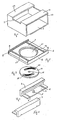
Figs. 1, 2, 3, 4 and 5 ofsheet 1/9 show the components of the support. -
Fig. 6 ofsheet 2/9 shows the same support assembled with a plate provided with a central hole having a circumferential shoulder on which a disc is laid down. -
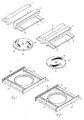
Figs. 7 and 8 ofsheet 3/9 show an exploded view of plate, disc and slides in closed and opened positions, respectively, which are capable of sliding along the plate and driven by a suitable disc provided with elliptical slots. -
Figs. 9 and 10 of sheet 4/9 show one of the slides put into the base disc causing it to slide in two different positions. -
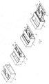
Figs. 11 and 12 ofsheet 5/9 show perspective views of the slides in a capsized position to better show their movement. -
Figs. 13 and 14 ofsheet 6/9 show the slides in a disengaged from and engaged with the board, respectively. -
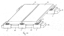
Fig. 15 of sheet 7/9 shows a perspective view of several juxtaposed boards with the slides being in the locked position of the boards. -
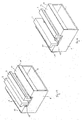
Fig. 16 of sheet 8/9 shows the same view asFig. 15 but with the slides being in the released position of the boards. -
Figs. 17 and 18 ofsheet 9/9 show section views of the boards in the locked and released positions, respectively. - According to the above, the system makes use of a block (1) consisting of a hollow parallelepiped member provided at its upper face with a central, wide opening (2) through which two slides (3) with a L-shaped section can be inserted. The longer side of the L-shaped slide has an orthogonal tab (4) having a boss (5) beneath and at the centre of its length and grooves (6) along its shorter sides.
- The main portion of the support is a parallelepiped plate (7) having two side walls (8) provided at the upper end and internally with two female joints (9) that upon assembling engage male joints (10) at the upper edges of parallelepiped block (1).
- Such plate has at its centre two concentric holes (11) and (12) having different diameters so that a shoulder is formed between the two holes. There are two rails (13) at the sides of the holes.
- Another essential component of the support is a disc (14) which is provided with two elliptical slots (15) and (16) and a central hole (17).
- As can be seen, the support needs that the shorter sides (18) of the boards are shaped as shown in
Fig. 9 to be disengaged or engaged. According to what disclosed above and shown in the figures, the support can be assembled by inserting the two slides (3) through upper opening (2) formed in block (1) one into the left side, the other into the right side of the opening. - The insertion should take place so that the lower portion (4) of the slide is positioned under upper walls (19) of block (1). Plate (7) with disc (14) placed on the shoulder formed between holes (11) and (12) of block (1) is then inserted and brought upwards so that boss (5) of slides (3) are inserted into elliptical slots (15) and (16) as well as rails (13) of the plate are inserted into channels (6) of slides (3). At last, female joints (9) of the walls of plate (8) are engaged with male joints (10) of parallelepiped block (1).
- After the support is assembled, the slides are positioned at predetermined distances on wood profile (20) to be connected, as shown in sheets (7), (8) and (9). The two slides (3) are inserted with their channels (6) into rails (13) and guided to slide by a rectilinear length so as to approach or move apart from each other.
- The travel of the slides is determined by the stroke of bosses (5) in slots (15) and (16). The latter have an extension that does not allow the two slides to approach each other but keeps the same spaced apart by a gap allowing the insertion of a wrench that reaches hole (17) to rotate the disc that moves slides (3) by means of bosses (5).
- The support disclosed allows the boards of a wood floor to be blocked or released.
- The floor is laid by placing the supports onto wood profiles at a suitable distance from one another and by laying boards (22) above them. To this end, the shorter sides (18) of the boards are shaped as shown in
Fig. 9 . Thus, slides (3) are moved by means of a wrench which is inserted into hole (17) in the gap between the two slides of each block, the lower tab of which is thus inserted into cavity (21) to lock the boards. - The boards are released from the slides by an opposite movement of the slide.
- The system disclosed allows a wood floor to be laid easily and quickly without any hole into the boards and without using screws or nails.
- It allows everybody to replace one or more boards easily and quickly. Moreover the background of the floor can be overseen at any site of the flooring in case of restoration of the waterproof sheath without damaging the boards of the floor. In fact, the system of the invention allows the board to be recovered and laid again.
- Shape and structural modifications can be made to the invention within the scope of the same inventive concept which is defined by the following claims.
Claims (7)
- A system for lying wood floors, characterized in that the boards rest on suitable supports and are blocked or released by the movement of two slides that are inserted into a suitable cavity formed at the end of the shorter side of the boards.
- The system according to the preceding claim, characterized in that supports (1) consists of a parallelepiped having two slides (3) with a L-shaped section which are able to slide by approaching and moving apart from each other so that in their spaced apart relationship their shorter sides are inserted into a suitable cavity (21) formed in the shorter sides of the boards to lock the same, the movement of the slides being caused by a disc (14) provided with suitable elliptical slots (15) and (16) engaged by bosses (5) projecting from the longer sides of slides (3).
- The system according to the preceding claims, characterized in that disc (14) is supported by a plate (7) which is inserted within the block so as to engage the male section (10) of the surface of the support with its opposite surfaces with female section (9).
- The system according to the preceding claims, characterized in that suitable rails (13) of the plate guide the movement of the slides provided with corresponding grooves (6) formed in a tab which is orthogonal to the longer sides of the plate.
- The block according to the preceding claims, characterized in that it can be assembled and completely disassembled and consists of a parallelepiped, an inner plate, two slides and a disc provided with two slots and a central hole.
- The block according to the preceding claims, characterized in that in the released position of the boards the slides are spaced apart from each other by such a gap as to allow the insertion of a wrench until reaching the hole formed in the lower disc (14).
- The system according to the preceding claims, characterized in that the floor is laid by spacing apart the blocks on wood profiles at suitable distances, whereupon the boards are laid onto the blocks and locked as disclosed in claim 2.
Applications Claiming Priority (1)
| Application Number | Priority Date | Filing Date | Title |
|---|---|---|---|
| ITNA2009A000041A IT1397545B1 (en) | 2009-06-25 | 2009-06-25 | LAYING SYSTEM FOR WOODEN FLOORS FOR EXTERIORS AND FULLY INSPECTIVE INTERIORS. |
Publications (2)
| Publication Number | Publication Date |
|---|---|
| EP2267241A1 true EP2267241A1 (en) | 2010-12-29 |
| EP2267241B1 EP2267241B1 (en) | 2014-11-26 |
Family
ID=42174031
Family Applications (1)
| Application Number | Title | Priority Date | Filing Date |
|---|---|---|---|
| EP10425199.6A Not-in-force EP2267241B1 (en) | 2009-06-25 | 2010-06-15 | A system for laying outdoor and indoor wood floors capable of being thoroughly overseen |
Country Status (2)
| Country | Link |
|---|---|
| EP (1) | EP2267241B1 (en) |
| IT (1) | IT1397545B1 (en) |
Cited By (8)
| Publication number | Priority date | Publication date | Assignee | Title |
|---|---|---|---|---|
| EP2481967A3 (en) * | 2011-01-28 | 2013-02-27 | DDC Design & Development GmbH & Co. KG | Catch holder element for reversible fixing of components in particular for the wall or ceiling fitting of projection screen systems |
| ITVI20110334A1 (en) * | 2011-12-23 | 2013-06-24 | C. | ANCHORAGE DEVICE FOR MODULAR FLOORING STRUCTURE AND PAVING STRUCTURE INCLUDING THE DEVICE |
| FR3001481A1 (en) * | 2013-01-29 | 2014-08-01 | Neolife | Deck board, has adjacent cells separated by intermediate washer, and fixing washer including subsidiary blocking surface to co-operate with blocking element of connection part that is used to fix board resulting from cutting support element |
| ITUB20154656A1 (en) * | 2015-10-14 | 2017-04-14 | Evodeck S R L S | SYSTEM FOR LOCKING AND UNLOCKING THE WOOD FLOORING CUSTOMS. |
| IT201800010700A1 (en) | 2018-11-29 | 2020-05-29 | Heco Italia Efg S R L | HOOKING GROUP FOR PANELS |
| CH715775A1 (en) * | 2019-01-25 | 2020-07-31 | Cadex Haltesystem | Plank connecting element for connecting the end faces or the long sides of a first and second adjacent plank of a terrace floor. |
| US20210324886A1 (en) * | 2020-04-15 | 2021-10-21 | Türk & Hillinger GmbH | Electric heater that can be clamped |
| IT202200006422A1 (en) * | 2022-03-31 | 2023-10-01 | Savytska Elvira | SYSTEM FOR THE INSTALLATION OF WOODEN, WPC and similar FLOORING |
Citations (6)
| Publication number | Priority date | Publication date | Assignee | Title |
|---|---|---|---|---|
| US5135415A (en) * | 1991-08-12 | 1992-08-04 | Nick Huber | Device for attaching electrical components to track |
| DE29707884U1 (en) * | 1997-05-02 | 1997-09-25 | Fennel Gmbh, 32549 Bad Oeynhausen | Connector for panels in particular |
| US20020172552A1 (en) * | 2001-05-15 | 2002-11-21 | Bedi Daljit S. | Clock lock |
| WO2008000747A1 (en) * | 2006-06-28 | 2008-01-03 | Avantgarde Srl | Supporting frame for covering elements and clamping element used in the supporting frame |
| WO2008093383A1 (en) * | 2007-02-02 | 2008-08-07 | Gio'speedy Di Giovanni Iovene | System for the removable fastening of wood-blocks for wood flooring or the like |
| EP1990549A1 (en) * | 2007-05-08 | 2008-11-12 | Franz Baur | Connecting device and method for creating a connection between a first component and a second component |
-
2009
- 2009-06-25 IT ITNA2009A000041A patent/IT1397545B1/en active
-
2010
- 2010-06-15 EP EP10425199.6A patent/EP2267241B1/en not_active Not-in-force
Patent Citations (6)
| Publication number | Priority date | Publication date | Assignee | Title |
|---|---|---|---|---|
| US5135415A (en) * | 1991-08-12 | 1992-08-04 | Nick Huber | Device for attaching electrical components to track |
| DE29707884U1 (en) * | 1997-05-02 | 1997-09-25 | Fennel Gmbh, 32549 Bad Oeynhausen | Connector for panels in particular |
| US20020172552A1 (en) * | 2001-05-15 | 2002-11-21 | Bedi Daljit S. | Clock lock |
| WO2008000747A1 (en) * | 2006-06-28 | 2008-01-03 | Avantgarde Srl | Supporting frame for covering elements and clamping element used in the supporting frame |
| WO2008093383A1 (en) * | 2007-02-02 | 2008-08-07 | Gio'speedy Di Giovanni Iovene | System for the removable fastening of wood-blocks for wood flooring or the like |
| EP1990549A1 (en) * | 2007-05-08 | 2008-11-12 | Franz Baur | Connecting device and method for creating a connection between a first component and a second component |
Cited By (9)
| Publication number | Priority date | Publication date | Assignee | Title |
|---|---|---|---|---|
| EP2481967A3 (en) * | 2011-01-28 | 2013-02-27 | DDC Design & Development GmbH & Co. KG | Catch holder element for reversible fixing of components in particular for the wall or ceiling fitting of projection screen systems |
| ITVI20110334A1 (en) * | 2011-12-23 | 2013-06-24 | C. | ANCHORAGE DEVICE FOR MODULAR FLOORING STRUCTURE AND PAVING STRUCTURE INCLUDING THE DEVICE |
| FR3001481A1 (en) * | 2013-01-29 | 2014-08-01 | Neolife | Deck board, has adjacent cells separated by intermediate washer, and fixing washer including subsidiary blocking surface to co-operate with blocking element of connection part that is used to fix board resulting from cutting support element |
| ITUB20154656A1 (en) * | 2015-10-14 | 2017-04-14 | Evodeck S R L S | SYSTEM FOR LOCKING AND UNLOCKING THE WOOD FLOORING CUSTOMS. |
| IT201800010700A1 (en) | 2018-11-29 | 2020-05-29 | Heco Italia Efg S R L | HOOKING GROUP FOR PANELS |
| EP3660241A1 (en) | 2018-11-29 | 2020-06-03 | Heco Italia EFG S.r.l. | Coupling unit for panels |
| CH715775A1 (en) * | 2019-01-25 | 2020-07-31 | Cadex Haltesystem | Plank connecting element for connecting the end faces or the long sides of a first and second adjacent plank of a terrace floor. |
| US20210324886A1 (en) * | 2020-04-15 | 2021-10-21 | Türk & Hillinger GmbH | Electric heater that can be clamped |
| IT202200006422A1 (en) * | 2022-03-31 | 2023-10-01 | Savytska Elvira | SYSTEM FOR THE INSTALLATION OF WOODEN, WPC and similar FLOORING |
Also Published As
| Publication number | Publication date |
|---|---|
| ITNA20090041A1 (en) | 2010-12-26 |
| EP2267241B1 (en) | 2014-11-26 |
| IT1397545B1 (en) | 2013-01-16 |
Similar Documents
| Publication | Publication Date | Title |
|---|---|---|
| EP2267241A1 (en) | A system for laying outdoor and indoor wood floors capable of being thoroughly overseen | |
| DE3322102C2 (en) | ||
| US7010894B1 (en) | Covering, covering elements and installing and disassembling method | |
| CA2809984C (en) | Covering panel and method for assembling a plurality of same | |
| US20180119429A1 (en) | Covering of rectangular or square panels which are laid to form an assembly | |
| US20160333579A1 (en) | Connector | |
| CN102844506A (en) | floor components | |
| NO323234B1 (en) | Floating floor system, a sliding block for use in such a floor system and a method for mounting such a floor system. | |
| CA2840890C (en) | Fastening system | |
| BRPI0408688A (en) | device for connecting building boards, especially floor panels | |
| ATE498748T1 (en) | DEVICE FOR CONNECTING AND LOCKING TWO BUILDING PANELS, IN PARTICULAR FLOOR PANELS | |
| KR101469709B1 (en) | Construction Masonry Brick Walls Coupling Apparatus | |
| WO2009075998A3 (en) | Locking mechanism for flooring boards | |
| RU2009139404A (en) | WALL FRAME DESIGN | |
| CA2746404A1 (en) | Improved connections for suspended ceiling system | |
| EP2860833A3 (en) | Floor element for electrical installations and system with floor elements | |
| EP3282066A1 (en) | A fastening member for fastening elongated elements and an arrangement comprising the same | |
| US20130269280A1 (en) | Ceiling plank | |
| CN205677178U (en) | A kind of light decorative plate being easy to Fast Installation | |
| US9560924B2 (en) | Connection assembly | |
| CN205677179U (en) | A kind of fast-assembling guide rail for light decorative plate and light decorative plate | |
| EP1849926A3 (en) | Mobile partition wall | |
| US20210363766A1 (en) | Spacer for installation of flooring system | |
| EP1728941A3 (en) | Laying system for making a wooden floor, wall or false ceiling | |
| EP2149651A1 (en) | A system for lying wooden floors having a square or rectangle pattern without nails, screws or glue |
Legal Events
| Date | Code | Title | Description |
|---|---|---|---|
| PUAI | Public reference made under article 153(3) epc to a published international application that has entered the european phase |
Free format text: ORIGINAL CODE: 0009012 |
|
| AK | Designated contracting states |
Kind code of ref document: A1 Designated state(s): AL AT BE BG CH CY CZ DE DK EE ES FI FR GB GR HR HU IE IS IT LI LT LU LV MC MK MT NL NO PL PT RO SE SI SK SM TR |
|
| AX | Request for extension of the european patent |
Extension state: BA ME RS |
|
| 17P | Request for examination filed |
Effective date: 20110614 |
|
| GRAP | Despatch of communication of intention to grant a patent |
Free format text: ORIGINAL CODE: EPIDOSNIGR1 |
|
| INTG | Intention to grant announced |
Effective date: 20140728 |
|
| GRAS | Grant fee paid |
Free format text: ORIGINAL CODE: EPIDOSNIGR3 |
|
| GRAA | (expected) grant |
Free format text: ORIGINAL CODE: 0009210 |
|
| AK | Designated contracting states |
Kind code of ref document: B1 Designated state(s): AL AT BE BG CH CY CZ DE DK EE ES FI FR GB GR HR HU IE IS IT LI LT LU LV MC MK MT NL NO PL PT RO SE SI SK SM TR |
|
| REG | Reference to a national code |
Ref country code: GB Ref legal event code: FG4D |
|
| REG | Reference to a national code |
Ref country code: CH Ref legal event code: EP |
|
| REG | Reference to a national code |
Ref country code: AT Ref legal event code: REF Ref document number: 698322 Country of ref document: AT Kind code of ref document: T Effective date: 20141215 |
|
| REG | Reference to a national code |
Ref country code: IE Ref legal event code: FG4D |
|
| REG | Reference to a national code |
Ref country code: DE Ref legal event code: R096 Ref document number: 602010020512 Country of ref document: DE Effective date: 20150108 |
|
| REG | Reference to a national code |
Ref country code: NL Ref legal event code: VDEP Effective date: 20141126 |
|
| REG | Reference to a national code |
Ref country code: AT Ref legal event code: MK05 Ref document number: 698322 Country of ref document: AT Kind code of ref document: T Effective date: 20141126 |
|
| REG | Reference to a national code |
Ref country code: LT Ref legal event code: MG4D |
|
| PG25 | Lapsed in a contracting state [announced via postgrant information from national office to epo] |
Ref country code: IS Free format text: LAPSE BECAUSE OF FAILURE TO SUBMIT A TRANSLATION OF THE DESCRIPTION OR TO PAY THE FEE WITHIN THE PRESCRIBED TIME-LIMIT Effective date: 20150326 Ref country code: NO Free format text: LAPSE BECAUSE OF FAILURE TO SUBMIT A TRANSLATION OF THE DESCRIPTION OR TO PAY THE FEE WITHIN THE PRESCRIBED TIME-LIMIT Effective date: 20150226 Ref country code: ES Free format text: LAPSE BECAUSE OF FAILURE TO SUBMIT A TRANSLATION OF THE DESCRIPTION OR TO PAY THE FEE WITHIN THE PRESCRIBED TIME-LIMIT Effective date: 20141126 Ref country code: FI Free format text: LAPSE BECAUSE OF FAILURE TO SUBMIT A TRANSLATION OF THE DESCRIPTION OR TO PAY THE FEE WITHIN THE PRESCRIBED TIME-LIMIT Effective date: 20141126 Ref country code: PT Free format text: LAPSE BECAUSE OF FAILURE TO SUBMIT A TRANSLATION OF THE DESCRIPTION OR TO PAY THE FEE WITHIN THE PRESCRIBED TIME-LIMIT Effective date: 20150326 Ref country code: NL Free format text: LAPSE BECAUSE OF FAILURE TO SUBMIT A TRANSLATION OF THE DESCRIPTION OR TO PAY THE FEE WITHIN THE PRESCRIBED TIME-LIMIT Effective date: 20141126 Ref country code: LT Free format text: LAPSE BECAUSE OF FAILURE TO SUBMIT A TRANSLATION OF THE DESCRIPTION OR TO PAY THE FEE WITHIN THE PRESCRIBED TIME-LIMIT Effective date: 20141126 |
|
| PG25 | Lapsed in a contracting state [announced via postgrant information from national office to epo] |
Ref country code: CY Free format text: LAPSE BECAUSE OF FAILURE TO SUBMIT A TRANSLATION OF THE DESCRIPTION OR TO PAY THE FEE WITHIN THE PRESCRIBED TIME-LIMIT Effective date: 20141126 Ref country code: SE Free format text: LAPSE BECAUSE OF FAILURE TO SUBMIT A TRANSLATION OF THE DESCRIPTION OR TO PAY THE FEE WITHIN THE PRESCRIBED TIME-LIMIT Effective date: 20141126 Ref country code: LV Free format text: LAPSE BECAUSE OF FAILURE TO SUBMIT A TRANSLATION OF THE DESCRIPTION OR TO PAY THE FEE WITHIN THE PRESCRIBED TIME-LIMIT Effective date: 20141126 Ref country code: GR Free format text: LAPSE BECAUSE OF FAILURE TO SUBMIT A TRANSLATION OF THE DESCRIPTION OR TO PAY THE FEE WITHIN THE PRESCRIBED TIME-LIMIT Effective date: 20150227 Ref country code: AT Free format text: LAPSE BECAUSE OF FAILURE TO SUBMIT A TRANSLATION OF THE DESCRIPTION OR TO PAY THE FEE WITHIN THE PRESCRIBED TIME-LIMIT Effective date: 20141126 Ref country code: HR Free format text: LAPSE BECAUSE OF FAILURE TO SUBMIT A TRANSLATION OF THE DESCRIPTION OR TO PAY THE FEE WITHIN THE PRESCRIBED TIME-LIMIT Effective date: 20141126 |
|
| PG25 | Lapsed in a contracting state [announced via postgrant information from national office to epo] |
Ref country code: DK Free format text: LAPSE BECAUSE OF FAILURE TO SUBMIT A TRANSLATION OF THE DESCRIPTION OR TO PAY THE FEE WITHIN THE PRESCRIBED TIME-LIMIT Effective date: 20141126 Ref country code: RO Free format text: LAPSE BECAUSE OF FAILURE TO SUBMIT A TRANSLATION OF THE DESCRIPTION OR TO PAY THE FEE WITHIN THE PRESCRIBED TIME-LIMIT Effective date: 20141126 Ref country code: SK Free format text: LAPSE BECAUSE OF FAILURE TO SUBMIT A TRANSLATION OF THE DESCRIPTION OR TO PAY THE FEE WITHIN THE PRESCRIBED TIME-LIMIT Effective date: 20141126 Ref country code: CZ Free format text: LAPSE BECAUSE OF FAILURE TO SUBMIT A TRANSLATION OF THE DESCRIPTION OR TO PAY THE FEE WITHIN THE PRESCRIBED TIME-LIMIT Effective date: 20141126 Ref country code: EE Free format text: LAPSE BECAUSE OF FAILURE TO SUBMIT A TRANSLATION OF THE DESCRIPTION OR TO PAY THE FEE WITHIN THE PRESCRIBED TIME-LIMIT Effective date: 20141126 |
|
| REG | Reference to a national code |
Ref country code: DE Ref legal event code: R097 Ref document number: 602010020512 Country of ref document: DE |
|
| PG25 | Lapsed in a contracting state [announced via postgrant information from national office to epo] |
Ref country code: PL Free format text: LAPSE BECAUSE OF FAILURE TO SUBMIT A TRANSLATION OF THE DESCRIPTION OR TO PAY THE FEE WITHIN THE PRESCRIBED TIME-LIMIT Effective date: 20141126 |
|
| PLBE | No opposition filed within time limit |
Free format text: ORIGINAL CODE: 0009261 |
|
| STAA | Information on the status of an ep patent application or granted ep patent |
Free format text: STATUS: NO OPPOSITION FILED WITHIN TIME LIMIT |
|
| 26N | No opposition filed |
Effective date: 20150827 |
|
| PG25 | Lapsed in a contracting state [announced via postgrant information from national office to epo] |
Ref country code: IT Free format text: LAPSE BECAUSE OF FAILURE TO SUBMIT A TRANSLATION OF THE DESCRIPTION OR TO PAY THE FEE WITHIN THE PRESCRIBED TIME-LIMIT Effective date: 20141126 |
|
| REG | Reference to a national code |
Ref country code: DE Ref legal event code: R119 Ref document number: 602010020512 Country of ref document: DE |
|
| PG25 | Lapsed in a contracting state [announced via postgrant information from national office to epo] |
Ref country code: MC Free format text: LAPSE BECAUSE OF FAILURE TO SUBMIT A TRANSLATION OF THE DESCRIPTION OR TO PAY THE FEE WITHIN THE PRESCRIBED TIME-LIMIT Effective date: 20141126 |
|
| REG | Reference to a national code |
Ref country code: CH Ref legal event code: PL |
|
| GBPC | Gb: european patent ceased through non-payment of renewal fee |
Effective date: 20150615 |
|
| PG25 | Lapsed in a contracting state [announced via postgrant information from national office to epo] |
Ref country code: SI Free format text: LAPSE BECAUSE OF FAILURE TO SUBMIT A TRANSLATION OF THE DESCRIPTION OR TO PAY THE FEE WITHIN THE PRESCRIBED TIME-LIMIT Effective date: 20141126 Ref country code: LU Free format text: LAPSE BECAUSE OF FAILURE TO SUBMIT A TRANSLATION OF THE DESCRIPTION OR TO PAY THE FEE WITHIN THE PRESCRIBED TIME-LIMIT Effective date: 20150615 |
|
| REG | Reference to a national code |
Ref country code: IE Ref legal event code: MM4A |
|
| REG | Reference to a national code |
Ref country code: FR Ref legal event code: ST Effective date: 20160229 |
|
| PG25 | Lapsed in a contracting state [announced via postgrant information from national office to epo] |
Ref country code: CH Free format text: LAPSE BECAUSE OF NON-PAYMENT OF DUE FEES Effective date: 20150630 Ref country code: GB Free format text: LAPSE BECAUSE OF NON-PAYMENT OF DUE FEES Effective date: 20150615 Ref country code: LI Free format text: LAPSE BECAUSE OF NON-PAYMENT OF DUE FEES Effective date: 20150630 Ref country code: IE Free format text: LAPSE BECAUSE OF NON-PAYMENT OF DUE FEES Effective date: 20150615 Ref country code: DE Free format text: LAPSE BECAUSE OF NON-PAYMENT OF DUE FEES Effective date: 20160101 |
|
| PG25 | Lapsed in a contracting state [announced via postgrant information from national office to epo] |
Ref country code: FR Free format text: LAPSE BECAUSE OF NON-PAYMENT OF DUE FEES Effective date: 20150630 |
|
| PG25 | Lapsed in a contracting state [announced via postgrant information from national office to epo] |
Ref country code: MT Free format text: LAPSE BECAUSE OF FAILURE TO SUBMIT A TRANSLATION OF THE DESCRIPTION OR TO PAY THE FEE WITHIN THE PRESCRIBED TIME-LIMIT Effective date: 20141126 |
|
| PG25 | Lapsed in a contracting state [announced via postgrant information from national office to epo] |
Ref country code: SM Free format text: LAPSE BECAUSE OF FAILURE TO SUBMIT A TRANSLATION OF THE DESCRIPTION OR TO PAY THE FEE WITHIN THE PRESCRIBED TIME-LIMIT Effective date: 20141126 Ref country code: HU Free format text: LAPSE BECAUSE OF FAILURE TO SUBMIT A TRANSLATION OF THE DESCRIPTION OR TO PAY THE FEE WITHIN THE PRESCRIBED TIME-LIMIT; INVALID AB INITIO Effective date: 20100615 Ref country code: BG Free format text: LAPSE BECAUSE OF FAILURE TO SUBMIT A TRANSLATION OF THE DESCRIPTION OR TO PAY THE FEE WITHIN THE PRESCRIBED TIME-LIMIT Effective date: 20141126 |
|
| PG25 | Lapsed in a contracting state [announced via postgrant information from national office to epo] |
Ref country code: TR Free format text: LAPSE BECAUSE OF FAILURE TO SUBMIT A TRANSLATION OF THE DESCRIPTION OR TO PAY THE FEE WITHIN THE PRESCRIBED TIME-LIMIT Effective date: 20141126 |
|
| PG25 | Lapsed in a contracting state [announced via postgrant information from national office to epo] |
Ref country code: BE Free format text: LAPSE BECAUSE OF FAILURE TO SUBMIT A TRANSLATION OF THE DESCRIPTION OR TO PAY THE FEE WITHIN THE PRESCRIBED TIME-LIMIT Effective date: 20141126 |
|
| PG25 | Lapsed in a contracting state [announced via postgrant information from national office to epo] |
Ref country code: MK Free format text: LAPSE BECAUSE OF FAILURE TO SUBMIT A TRANSLATION OF THE DESCRIPTION OR TO PAY THE FEE WITHIN THE PRESCRIBED TIME-LIMIT Effective date: 20141126 |
|
| PG25 | Lapsed in a contracting state [announced via postgrant information from national office to epo] |
Ref country code: AL Free format text: LAPSE BECAUSE OF FAILURE TO SUBMIT A TRANSLATION OF THE DESCRIPTION OR TO PAY THE FEE WITHIN THE PRESCRIBED TIME-LIMIT Effective date: 20141126 |