EP2266758A2 - Retractable prewinder assembly with infinite adjustability for installation of helically coiled wire inserts - Google Patents
Retractable prewinder assembly with infinite adjustability for installation of helically coiled wire inserts Download PDFInfo
- Publication number
- EP2266758A2 EP2266758A2 EP10166100A EP10166100A EP2266758A2 EP 2266758 A2 EP2266758 A2 EP 2266758A2 EP 10166100 A EP10166100 A EP 10166100A EP 10166100 A EP10166100 A EP 10166100A EP 2266758 A2 EP2266758 A2 EP 2266758A2
- Authority
- EP
- European Patent Office
- Prior art keywords
- prewinder
- stall
- mandrel
- drive
- insert
- Prior art date
- Legal status (The legal status is an assumption and is not a legal conclusion. Google has not performed a legal analysis and makes no representation as to the accuracy of the status listed.)
- Granted
Links
Images









Classifications
-
- B—PERFORMING OPERATIONS; TRANSPORTING
- B25—HAND TOOLS; PORTABLE POWER-DRIVEN TOOLS; MANIPULATORS
- B25B—TOOLS OR BENCH DEVICES NOT OTHERWISE PROVIDED FOR, FOR FASTENING, CONNECTING, DISENGAGING, OR HOLDING
- B25B27/00—Hand tools, specially adapted for fitting together or separating parts or objects whether or not involving some deformation, not otherwise provided for
- B25B27/14—Hand tools, specially adapted for fitting together or separating parts or objects whether or not involving some deformation, not otherwise provided for for assembling objects other than by press fit or detaching same
- B25B27/143—Hand tools, specially adapted for fitting together or separating parts or objects whether or not involving some deformation, not otherwise provided for for assembling objects other than by press fit or detaching same for installing wire thread inserts or tubular threaded inserts
-
- Y—GENERAL TAGGING OF NEW TECHNOLOGICAL DEVELOPMENTS; GENERAL TAGGING OF CROSS-SECTIONAL TECHNOLOGIES SPANNING OVER SEVERAL SECTIONS OF THE IPC; TECHNICAL SUBJECTS COVERED BY FORMER USPC CROSS-REFERENCE ART COLLECTIONS [XRACs] AND DIGESTS
- Y10—TECHNICAL SUBJECTS COVERED BY FORMER USPC
- Y10T—TECHNICAL SUBJECTS COVERED BY FORMER US CLASSIFICATION
- Y10T29/00—Metal working
- Y10T29/49—Method of mechanical manufacture
- Y10T29/49764—Method of mechanical manufacture with testing or indicating
- Y10T29/49771—Quantitative measuring or gauging
-
- Y—GENERAL TAGGING OF NEW TECHNOLOGICAL DEVELOPMENTS; GENERAL TAGGING OF CROSS-SECTIONAL TECHNOLOGIES SPANNING OVER SEVERAL SECTIONS OF THE IPC; TECHNICAL SUBJECTS COVERED BY FORMER USPC CROSS-REFERENCE ART COLLECTIONS [XRACs] AND DIGESTS
- Y10—TECHNICAL SUBJECTS COVERED BY FORMER USPC
- Y10T—TECHNICAL SUBJECTS COVERED BY FORMER US CLASSIFICATION
- Y10T29/00—Metal working
- Y10T29/53—Means to assemble or disassemble
- Y10T29/53687—Means to assemble or disassemble by rotation of work part
- Y10T29/53691—Means to insert or remove helix
Definitions
- the present disclosure relates to devices and methods for installing helically coiled inserts.
- Helically coiled wire inserts both of tanged or tangless design can be inserted using hand tools, electrical, battery powered, or pneumatic tools.
- Coarse thread size inserts such as thread sizes 4-40, 6-32, 10-24, 1 ⁇ 4-20, etc., are relatively stiff or rigid and can be installed using a predetermined mandrel.
- Fine thread size inserts such as for thread sizes 4-48, 6-40, 8-36, 10-32, 1 ⁇ 4-28, etc., are commonly flexible and may not retain their shape during installation.
- Fine thread size inserts therefore commonly require a pre-winder to be used in conjunction with a mandrel to help reduce the outside diameter of the inserts and to align the coils of the wire insert to the correct pitch so they can be more easily installed into a tapped aperture of for example a work piece or fastener body.
- Pre-winders are known for use with hand tools, electric, battery operated, and/or pneumatic power tools, however known pre-winders for these tools for the installation of helically coiled inserts often also require spacers or shims to accommodate differences in insert length or installation depth. Installation of spacers or shims normally requires stocking multiple sizes of parts, with associated additional part costs, time delay in their installation, and defective parts which do not receive the properly installed insert.
- spacers or shims commonly requires disassembly of the tool or prewinder followed by installation of the necessary spacers or shims.
- the disassembly time further adds costs and time delay to completion of the component.
- the tool must then be reassembled and tested with the shims and spacers installed. If proper installation depth is not achieved, the process must be repeated until the appropriate shims or inserts are installed to provide the desired coil installation depth. This repetition further increases costs and time delays.
- An additional problem of know installation tools is providing a positive, repeatable stall position for the motor when the coil has reached an intended installation depth which can cause tool jamming.
- a prewinder apparatus attached to a drive tool for installation of a helical coil insert includes a body connected to the drive tool.
- An adapter rotatable with respect to the body is releasably connected to the body at operator selected ones of a plurality of rotated positions.
- a prewinder portion is slidably displaceable into and out of the body coaxial to a longitudinal axis of the body and the adapter, and biased by a first biasing member toward an extended position.
- a mandrel is axially extensible from the prewinder portion when the prewinder portion is slidably displaced into the body against a biasing force of the first biasing member. The mandrel is adapted to engage the helical coil insert to rotatably insert the coil insert.
- An adapter is rotatable with respect to the body and is releasably connected to the body at operator selected ones of a plurality of rotated positions.
- a prewinder portion is slidably displaceable into and out of the body coaxial to a longitudinal axis of the body and the adapter.
- the prewinder portion is slidably translatable into the body until a fastener engaged with the prewinder portion contacts a stop member defining a predetermined depth of insertion for the helical coil insert.
- a mandrel is axially extensible from the prewinder portion when the prewinder portion is slidably displaced into the body. The mandrel is adapted to engage the helical coil insert to rotatably insert the helical coil insert.
- a prewinder apparatus attached to a drive tool for installation of a helical coil insert includes a clutch assembly having a stall sleeve having a plurality of inner cavity threads.
- a stall coupling is both slidably and threadably receivable within an inner bore of the stall sleeve and further includes a plurality of outer perimeter threads adapted to be threadably engaged with the plurality of inner cavity threads of the stall sleeve.
- a drive socket is connected for rotation to the drive tool and axially translatable within the stall coupling. Upon full threaded engagement of the outer perimeter threads with the inner cavity threads an end face of the stall coupling contacts a wall of the stall sleeve preventing further axial translation of the stall coupling to frictionally stall the drive tool.
- a stall assembly includes a stall stop member threadably engaged with the body.
- a stall sleeve is slidably received in the stall stop member.
- a mandrel drive member having a drive end is adapted to releasably engage with the slot to rotate the mandrel, the mandrel drive member slidably received in the stall sleeve.
- a stall driver slidably is received within an inner diameter portion of mandrel drive member and having a radially extending flange.
- a fastener frictionally engaged with the stall driver and freely received in an elongated aperture of each of the stall sleeve and the mandrel drive member is adapted to co-rotate the stall sleeve and the mandrel drive member when the stall driver is rotated by the drive tool.
- a tubular body end of the stall sleeve contacts the radially extending flange of the stall driver to stall the drive tool.
- a prewinder apparatus attached to a drive tool for installation of a helical coil insert includes a body connected to the drive tool, and a mandrel axially extensible from the body and having a mandrel flange end including a slot.
- the mandrel is adapted to engage the helical coil insert to rotatably insert the coil insert.
- a drive member is releasably engaged to the mandrel and adapted to rotate the mandrel.
- a stall assembly includes: a stall stop member threadably engaged with the body; a stall sleeve slidably received in the stall stop member; a mandrel drive member having a drive end adapted to releasably engage with the slot to rotate the mandrel, the mandrel drive member slidably received in the stall sleeve; a stall driver slidably received within an inner diameter portion of mandrel drive member and having a radially extending flange; and a fastener frictionally engaged with the stall driver and freely received in an elongated aperture of each of the stall sleeve and the mandrel drive member adapted to co-rotate the stall sleeve and the mandrel drive member when the stall driver is rotated by the drive tool.
- a prewinder apparatus attached to a drive tool for installation of a helical coil insert includes a body connected to the drive tool.
- a prewinder portion is movable with respect to the body.
- a mandrel axially extensible from the prewinder portion is adapted to engage the helical coil insert to rotatably insert the coil insert.
- a drive system is adapted to rotate the mandrel and translate the mandrel in each of an installation direction and a retraction direction.
- a disengagement mechanism is adapted to disengage the mandrel from the drive system when the helical coil insert reaches an installed position by translation of the mandrel in the installation direction.
- a stall mechanism is adapted to stop rotation of the mandrel when the mandrel is retracted in the retraction direction to a fully retracted position.
- Example embodiments are provided so that this disclosure will be thorough, and will fully convey the scope to those who are skilled in the art. Numerous specific details are set forth such as examples of specific components, devices, and methods, to provide a thorough understanding of embodiments of the present disclosure. It will be apparent to those skilled in the art that specific details need not be employed, that example embodiments may be embodied in many different forms and that neither should be construed to limit the scope of the disclosure. In some example embodiments, well-known processes, well-known device structures, and well-known technologies are not described in detail.
- first, second, third, etc. may be used herein to describe various elements, components, regions, layers and/or sections, these elements, components, regions, layers and/or sections should not be limited by these terms. These terms may be only used to distinguish one element, component, region, layer or section from another region, layer or section. Terms such as “first,” “second,” and other numerical terms when used herein do not imply a sequence or order unless clearly indicated by the context. Thus, a first element, component, region, layer or section discussed below could be termed a second element, component, region, layer or section without departing from the teachings of the example embodiments.
- spatially relative terms such as “inner,” “outer,” “beneath”, “below”, “lower”, “above”, “upper” and the like, may be used herein for ease of description to describe one element or feature's relationship to another element(s) or feature(s) as illustrated in the figures.
- Spatially relative terms may be intended to encompass different orientations of the device in use or operation in addition to the orientation depicted in the figures. For example, if the device in the figures is turned over, elements described as “below” or “beneath” other elements or features would then be oriented “above” the other elements or features.
- the example term “below” can encompass both an orientation of above and below.
- the device may be otherwise oriented (rotated 90 degrees or at other orientations) and the spatially relative descriptors used herein interpreted accordingly.
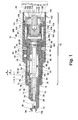
- a retractable prewinder apparatus 10 includes a disengagement mechanism or prewinder drive assembly 12 having a prewinder portion 14 releasably connected to the prewinder drive assembly 12.
- a mandrel 16 axially disposed in prewinder drive assembly 12 and extending through prewinder portion 14 is rotated by the prewinder drive assembly 12 to insert a helically coiled insert 18.
- Motive drive force to rotate portions of the prewinder drive assembly 12 including mandrel 16 can be provided using a tool 20 such as an electric motor powered for example by a battery or 110 volt AC power, a pneumatic drive such as air or hydraulic fluid, or similar drive device.
- Prewinder portion 14 includes a predominantly tubular shaped prewinder body 22 having a longitudinal cavity 24 coaxially aligned with a threaded longitudinal aperture 26. Threaded longitudinal aperture 26 is adapted to threadably receive a threaded body portion 28 of mandrel 16.
- the helically coiled insert 18 is positioned within an insert receiving cavity 30 prior to rotation of the mandrel 16.
- a coil engagement end 32 of mandrel 16 engages the helically coiled insert 18 to rotatably direct the helically coiled insert 18 into a coil diameter reducing aperture 34 created in a coil reducing member 36 which defines a free end of prewinder portion 14.
- Coil diameter reducing aperture 34 has a predefined aperture size to suit installation of the helically coiled insert 18 in one of a plurality of panel apertures which will be described in reference to Figure 18 .
- Prewinder portion 14 is axially slidably received in an adapter 38 within a first adapter portion 39.
- First adapter portion 39 is homogeneously and integrally connected to a second adapter portion 40 with first adapter portion 39 having a smaller outside diameter than second adapter portion 40.
- Adapter 38 is in turn releasably connected to a body 42 using at least one and according to several embodiments a plurality of fasteners 44, 44'.
- Fasteners 44, 44' are threadably inserted through fastener receiving apertures created in second adapter portion 40 proximate to a body end wall 46.
- a shank 48 of each of the fasteners 44, 44' is received in a circumferential slot 50 created in an extending sleeve 51 of body 42.
- the adapter 38 By loosening the fasteners 44, 44' with the shank 48 of each of the fasteners 44, 44' partially retained in the circumferential slot 50, the adapter 38 can be rotated with respect to body 42 while the shanks 48 slide within circumferential slot 50. Fasteners 44, 44' can then be tightened to engage their shanks 48 in contact with an end wall of circumferential slot 50 to frictionally engage second adapter portion 40 to body 42.
- first biasing member 54 is positioned within a cylinder portion 56 of body 42.
- first biasing member 54 is a compression spring made for example of a spring steel material.
- An internal diameter defined by cylinder portion 56 is sized to slidably receive the outside diameter of prewinder body 22.
- First biasing member 54 allows axial sliding of prewinder portion 14 in each of a assembly installation direction "A” and a assembly contraction direction “B” oppositely directed from assembly installation direction "A”.
- First biasing member 54 biases prewinder portion 14 in assembly installation direction "A”.
- First biasing member 54 is oriented to contact each of a prewinder end wall 58 of prewinder body 22 and a contact wall 60 defining an end wall of cylinder portion 56.
- a threaded insert 61 having an insert body 62 is translatable parallel to longitudinal axis 52 such that an insert longitudinal axis 63 oriented substantially transverse to longitudinal axis 52 can be positioned at the discretion of an operator of retractable prewinder apparatus 10.
- Insert body 62 is axially movable while being prevented from rotation within an adapter portion cavity 64.
- Adapter portion cavity 64 is created by removal of (or cast or molded without) a portion of the material of a tubular portion 65 of body 42.
- threaded insert 61 includes a plurality of insert threads 66 which threadably engage a plurality of insert engagement threads 68 created on an internal diameter of first adapter portion 39. Because insert body 62 is non-rotatably retained within adapter portion cavity 64, manual rotation of adapter 38 axially displaces insert body 62 using insert threads 66 by threaded engagement with insert engagement threads 68 of first adapter portion 39.
- Threaded insert 61 is used as a stop member which is axially and selectively positioned to control a dept of insertion of helically coiled insert 18.
- a stop fastener 70 includes a fastener head 72 which contacts an insert face 74 of threaded insert 61 to stop axial displacement of prewinder portion 14.
- An operator selectable distance between fastener head 72 and insert face 74 with the prewinder portion 14 in the fully extended position shown in Figure 1 defines a prewinder depth of insertion "C".
- Prewinder depth of insertion "C” is controlled by displacing the insert longitudinal axis 63 of threaded insert 61 by rotation of adapter 38 as described above.
- Stop fastener 70 further includes an insert shank 76 which is threadably received in a threaded bore 78 created in prewinder body 22. Contact between fastener head 72 of stop fastener 70 also provides an extension stop defining the fully extended position of prewinder portion 14 in the assembly installation direction "A" by contact between fastener head 72 and an end wall 79 of first adapter portion 39. Fastener head 72 is sized to be slidably received within adapter portion cavity 64.
- a ball 80 made for example from a metal or polymeric material is biased into engagement with one of a plurality of detent cavities 82 circumferentially created about extending sleeve 51 of body 42.
- Ball 80 is received in a ball cavity 84 created in second adapter portion 40.
- a biasing ring 86 made for example of a spring steel material is positioned in a circumferential slot created in second adapter portion 40 and allows ball 80 to deflect outwardly with respect to extending sleeve 51 in-between the various positions of the detent cavities 82.
- the detent cavities 82 are located at predetermined positions about the circumference of extending sleeve 51.
- movement of ball 80 to successive ones of detent cavities 82 corresponds with a predetermined increment such as 0.01 in (0.25 mm) of axial displacement for threaded insert 61.
- a predetermined increment such as 0.01 in (0.25 mm) of axial displacement for threaded insert 61.
- Prewinder drive assembly 12 further includes a disengagement mechanism such as a first clutch assembly 88.
- First clutch assembly 88 includes a clutch tube 90 slidably received in body 42.
- a mandrel flange end 92 is slidably received within an inner bore of clutch tube 90 such that mandrel flange end 92 with mandrel 16 is coaxially aligned with longitudinal axis 52.
- a second biasing member 94 is positioned within the bore of clutch tube 90 and contacts at opposite ends the mandrel flange end 92 and a clutch tube end wall 96 of clutch tube 90. Axial displacement of mandrel 16 and mandrel flange end 92 is therefore provided within the bore of clutch tube 90.
- a drive end 98 similar in shape to the slotted end of a slotted screwdriver extends from a drive member 100.
- Drive end 98 is received within a slot 101 created in mandrel flange end 92 such that rotation of drive member 100 operates to co-rotate mandrel 16.
- Drive member 100 is releasably coupled to clutch tube 90 using a fastener such as a first pin 102 slidably received through opposed apertures of clutch tube 90 and a corresponding aperture of drive member 100.
- Drive member 100 is similarly coupled to a drive coupling 104 using a fastener such as a second pin 106.
- Drive coupling 104 provides a drive socket 108 which slidably receives a male extending drive member (not shown) extending from tool 20.
- a socket mating connection 110 is created in drive socket 108 which is geometrically-shaped to correspond to the geometric shape of the drive member extending from tool 20. Common shapes used for this purpose include heptagon or hexagon shaped drive members.
- Prewinder drive assembly 12 further includes a stall mechanism such as a second clutch assembly 112.
- Second clutch assembly 112 includes a stall coupling 114 which has each of a third biasing member 116 and a fourth biasing member 118 positioned within the stall coupling 114.
- An engagement flange 120 radially extending outwardly from drive socket 108 defines a contact wall for each of the third and fourth biasing members 116, 118.
- a plurality of extending keys 121 integrally extend from an outer perimeter of engagement flange 120. The function of the extending keys 121 will be described in reference to Figures 3 , 13 , and 15 .
- Stall coupling 114 is both slidably and threadably receivable within an inner bore of a stall sleeve 122.
- a tubular insert 123 can also be provided within stall coupling 114 to maintain separation between the third and fourth biasing members 116, 118.
- Stall coupling 114 can include a plurality of left hand outer perimeter threads 124 which are threadably engaged with a plurality of left hand inner cavity threads 126 provided with stall sleeve 122.
- a perimeter radial flange 128 radially extending outwardly from stall sleeve 122 abuts against a contact face 130 of body 42 to fix the position of stall sleeve 122 within body 42.
- a plurality of inner body threads 132 are created proximate to a body/tool engagement end 133 of body 42.
- Inner body threads 132 are adapted to threadably receive corresponding threads of tool 20 to threadingly engage tool 20 to body 42, having perimeter radial flange 128 of stall sleeve 122 contacting both contact face 130 and a threaded insertion end of tool 20.
- Second clutch assembly 112 and in particular stall coupling 114, are slidably received within the inner cavity of stall sleeve 122 until outer perimeter threads 124 threadably engage inner cavity threads 126. Thereafter, further rotation of drive socket 108 pulls drive socket 108 in the assembly contraction direction "B" until an end face 134 of stall coupling 114 contacts an interior wall face 136 of stall sleeve 122 preventing further translation of stall coupling 114 and thereby frictionally stalling further rotation of tool 20.
- Installation of helically coiled insert 18 is accomplished by translating both tool 20 with the components of retractable prewinder apparatus 10 coaxially along longitudinal axis 52 in the assembly installation direction "A" until contact occurs between coil reducing member 36 at a prewinder contact end 138 with a panel. Further translation of retractable prewinder apparatus 10 in the assembly installation direction "A” together with operation of tool 20 causes prewinder portion 14 to move inwardly in the assembly contraction direction "B" which will be described in greater detail in reference to Figures 18 and 19 .
- a tool and driving sleeve assembly 140 includes tool 20 threadably coupled to body/tool engagement end 133 of body 42.
- Tubular portion 65 and extending sleeve 51 extend oppositely with respect to tool 20.
- the adapter portion cavity 64 of tubular portion 65 extends through a wall thickness of tubular portion 65.
- Fastener head 72 is slidably received within adapter portion cavity 64.
- Adapter 38 is not shown for clarity.
- a prewinder fully extended position 142 of prewinder portion 14 is shown.
- Individual ones of the detent cavities 82, 82' positioned about extending sleeve 51 can be located closer or further away from each other depending on a total quantity of detent cavities 82 selected.
- Mandrel 16 can further be divided into sections, for example having a body tube 143 connected to mandrel flange end 92 and a second portion (not shown) which extends through prewinder portion 14.
- a pin aperture 144 can be provided at a free end of body tube 143 to pin the second portion of mandrel 16 for extension through prewinder portion 14.
- Mandrel 16 and mandrel flange end 92 are slidably disposed within a clutch tube through bore 145 of clutch tube 90.
- Clutch tube 90 can further include oppositely positioned first and second clutch tube pin bores 146, 147 adapted to receive a pin for connecting clutch tube 90 to drive member 100.
- Drive member 100 can further include a first drive member pin bore 148 which is coaxially aligned with opposed internally located first and second semi-circular pin bores 149, 149' (only first semi-circular pin bore 149 is clearly visible).
- the drive end 98 of drive member 100 can engage with the slot 101 of mandrel 16 to rotate mandrel 16, or, drive end 98 can disengage from slot 101 as the mandrel threadably extends from prewinder portion 14 when helically coiled insert 18 reaches its predetermined set or installation depth, disengaging drive end 98 from slot 101.
- Drive member 100 can further include a drive member bore 150 which is adapted to slidably receive a first drive coupling portion 151 of drive coupling 104.
- a pin is slidably insertable through first drive member pin bore 148 and each of first and second semi-circular pin bores 149, 149', as well as through a drive coupling pin bore 152 created through first drive coupling portion 151.
- the first and second semi-circular pin bores 149, 149' of drive member 100 allow a degree of freedom of displacement for the pin relative to the first and second semi-circular pin bores 149, 149' to permit drive coupling 104 to disengage from drive member 100 under certain operating conditions.
- Drive coupling 104 further includes a perimeter surface 153 of engagement flange 120. The plurality of extending keys 121 extend radially outward with respect to perimeter surface 153.
- Stall coupling 114 includes an inner bore surface 154 into which is machined or formed a plurality of longitudinal slots 155, 155' which are oriented parallel to longitudinal axis 52. Individual ones of the plurality of extending keys 121 are received in the longitudinal slots 155. Longitudinal slots 155 allow axial sliding motion of drive coupling 104 with respect to stall coupling 114 while insertion of the extending keys 121 into the longitudinal slots 155 translates the rotational motion of drive coupling 104 to stall coupling 114.
- the outer perimeter threads 124 of stall coupling 114 are initially slidably received within a stall sleeve bore 156 of stall sleeve 122.
- the assembly of tool and driving sleeve assembly 140 is completed when the perimeter radial flange 128 of stall sleeve 122 abuts contact face 130.
- a flange perimeter surface 158 of perimeter radial flange 128 freely slides into body 42 having clearance with respect to inner body threads 132.
- a tool end 160 of tool 20 contacts an opposite face of perimeter radial flange 128 when a plurality of tool threads 162 are threadably engaged with inner body threads 132 until the tool contact end 163 of tool 20 contacts body/tool engagement end 133 of body 42.
- body 42 includes tubular portion 65 extending oppositely with respect to body/tool engagement end 133.
- Tubular portion 65 is created as a hollow tube-shaped extension of body 42 having a diameter smaller than a diameter of extending sleeve 51 which is integrally and homogeneously connected to body 42.
- the plurality of detent cavities 82, 82', 82" which are shown in this view are positioned at common intervals about the perimeter of extending sleeve 51.
- the quantity of detent cavities 82 can be varied and according to several embodiments each successive detent cavity 82 represents a linear displacement of the threaded insert 61 of approximately 0.010 in (0.25 cm) as ball 80 is partially received in successive ones of the detent cavities 82.
- the circumferential slot 50 is created by forming or machining material of extending sleeve 51.
- a main body portion 161 is also tubular in shape and provides body/tool engagement end 133.
- Main body portion 161 can have a diameter larger than a diameter of both tubular portion 65 and extending sleeve 51.
- a flat 164 is machined or formed parallel to a longitudinal axis 165 of tubular portion 65. Removal of material or formation of flat 164 creates the elongated adapter portion cavity 64.
- a cavity end wall 166 is created to provide a positive stop end for adapter portion cavity 64 to retain the structural integrity of tubular portion 65. Cavity end wall 166 is positioned proximate to an end face 167 of tubular portion 65.
- tubular portion 65 the increased diameter extending sleeve 51, and the largest diameter of main body portion 161 are evident.
- the flat 164 can be positioned at any perimeter portion of tubular portion 65 at the discretion of the manufacturer.
- contact wall 60 creates a division between cylinder portion 56 of tubular portion 65 and a clutch tube receiving bore 168 created in extending sleeve 51.
- Clutch tube receiving bore 168 opens into a clutch assembly receiving bore 170 created in main body portion 161 adapted to receive second clutch assembly 112.
- drive member 100 includes a cylindrical body 172 having first drive member pin bore 148 created transversely thereto.
- a raised shoulder 174 extends from an end wall 175.
- a drive end shaft 176 having a diameter smaller than a diameter of raised shoulder 174 extends integrally and homogeneously from end wall 175.
- a drive end shaft through-bore 178 is oriented substantially parallel to first drive member pin bore 148 and is oriented transverse to a longitudinal axis of drive member 100.
- Drive end 98 is created at a free end of drive end shaft 176.
- drive member 100 can be made from a metal including steel or stainless steel or a polymeric material.
- a concave circumferential recess 180 can be created about the perimeter of drive end shaft 176. Concave circumferential recess 180 can assist pin alignment during installation of first pin 102.
- a shoulder end face 182 of raised shoulder 174 provides a contact face for clutch tube 90 when clutch tube 90 is fully inserted into clutch tube receiving bore 168 of body 42.
- First and second semi-circular pin bores 149, 149' are co-axially aligned with first drive member pin bore 148.
- a drive end axis 184 is centrally disposed through drive end 98.
- a pin bore longitudinal axis 186 of first drive member pin bore 148 is oriented substantially transverse to drive end axis 184.
- a cylindrical body circumferential concave recess 188 can be created proximate to a free end 189 of cylindrical body 172. Circumferential concave recess 188 can be provided to assist with the alignment during installation of first pin 102 during installation into first drive member pin bore 148.
- drive coupling 104 can be made of a metal material such as steel or stainless steel or a polymeric material and can include a coupling portion end face 190 which can have a semi-circular shape.
- a concave circumferential slot 192 can be formed about the perimeter of first drive coupling portion 151 which also has the function of assisting with the alignment during installation of second pin 106 when installed in the drive coupling pin bore 152.
- Each of the extending keys 121 including exemplary extending keys 121, 121', 121" extend radially outwardly from the perimeter surface 153 of engagement flange 120.
- each of four extending keys 121, 121', 121 ", 121'” extend at a key height "D" from the perimeter surface 153 so that each of the extending keys 121 have a common geometry.
- a geometric-shaped bore 194 is created to form the socket mating connection 110 of drive socket 108.
- geometric-shaped bore 194 can have multiple faceted sides defining for example a heptagon or an octagon. These multiple sides are adapted to receive the tool engagement member (not shown) of tool 20.
- stall coupling 114 can be made from a metal material such as steel or stainless steel or a polymeric material.
- Stall coupling 114 includes a stall coupling tubular body 196 having integrally and homogeneously connected outer perimeter threads 124 (shown in block form). Outer perimeter threads 124 extend radially outwardly and above a surface level defined by stall coupling tubular body 196.
- a coupling end wall 198 is provided at one end of a coupling cavity 199 created in stall coupling tubular body 196 oppositely positioned with respect to outer perimeter threads 124.
- each successive one of the longitudinal slots 155, 155' 155", 155"' is oriented at a 90 degree increment with respect to proximate ones of the longitudinal slots 155.
- Each of the four longitudinal slots 155 are adapted to slidably receive one of the extending keys 121 of drive coupling 104. Engagement of the extending keys 121 into each of the longitudinal slots 155 therefore allows the drive coupling 104 to be slidably received within stall coupling 114 while transferring a rotational force of drive coupling 104 to stall coupling 114.
- the coupling end wall 198 provides a positive stop point for contact between engagement flange 120 of drive coupling 104 and stall coupling 114.
- the inner bore surface 154 of stall coupling 114 is adapted to slidably receive the perimeter surface 153 of engagement flange 120 of drive coupling 104.
- stall sleeve 122 can be created from a metal material such as steel or stainless steel or a polymeric material.
- Stall sleeve 122 includes a sleeve body 200 having a tubular shape.
- a cavity end wall 202 is created at one end of a sleeve cavity 204.
- Cavity end wall 202 provides a positive stop point for stall coupling 114 when threadably received in stall sleeve 122.
- perimeter radial flange 128 extends radially outwardly with respect to sleeve body 200 to provide for positive engagement and positioning of stall sleeve 122.
- stall sleeve 122 includes stall sleeve bore 156 which freely receives drive socket 108.
- Sleeve cavity 204 has a cavity diameter "E" which is larger than a diameter "F” defined by the plurality of the threads of inner cavity threads 126.
- retractable prewinder apparatus 10 operation of retractable prewinder apparatus 10 is as follows. As shown in Figure 1 , an initial position of retractable prewinder apparatus 10 provides prewinder portion 14 at a fully extended position biased by first biasing member 54 in the assembly installation direction "A". The threaded body portion 28 of mandrel 16 is fully retracted into the threaded longitudinal aperture 26 which provides clearance for insertion of a helically coiled insert 18 into the insert receiving cavity 30. Drive end 98 of drive member 100 is fully seated in the slot 101 of mandrel flange end 92.
- Threaded insert 61 is positioned at prewinder depth of insertion "C" based at least on a size of helically coiled insert 18 and the desired depth of insertion for helically coiled insert 18.
- Second clutch assembly 112 is in a non-engaged position with third and fourth biasing members 116, 118 in their fully extended positions and having outer perimeter threads 124 of stall coupling 114 disengaged from the plurality of inner cavity threads 126 of stall sleeve 122.
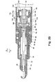
- retractable prewinder apparatus 10 is shown following operation to fully seat helically coiled insert 18.
- prewinder contact end 138 of coil reducing member 36 is brought into contact with a first panel side 208 of a panel 210.
- the longitudinal axis 52 of retractable prewinder apparatus 10 is coaxially aligned with an aperture axis 211 of an insert receiving aperture 212 formed in panel 210.
- Tool 20 is operated to co-rotate drive socket 108, drive member 100, clutch tube 90, and mandrel 16 in a first direction of rotation such as a clockwise direction of rotation.
- Rotation of mandrel 16 causes the threaded body portion 28 of mandrel 16 to threadably engage threaded longitudinal aperture 26 of prewinder portion 14 which pulls prewinder portion 14 in the assembly contraction direction "B" into cylinder portion 56, compressing the first biasing member 54.
- Coil engagement end 32 of mandrel 16 engages the helically coiled insert 18 to drive helically coiled insert 18 through coil diameter reducing aperture 34 of coil reducing member 36 which reduces the outside diameter of helically coiled insert 18 to suit the diameter of insert receiving aperture 212 of panel 210.
- Prewinder portion 14 is continuously withdrawn into cylinder portion 56 until fastener head 72 contacts insert face 74 of threaded insert 61.
- stall coupling 114 continues until end face 134 of stall coupling 114 contacts the interior wall face 136 of stall sleeve 122, preventing further translation of stall coupling 114 and thereby preventing further translation of mandrel 16 which frictionally stalls tool 20.
- fourth biasing member 118 of second clutch assembly 112 is compressed by contact with engagement flange 120 of drive coupling 104 which is substantially retained in its axial position.
- Initial compression of third biasing member 116 also begins to occur during this event by contact between engagement flange 120 and drive member 100.
- a disengagement mechanism or prewinder drive assembly 216 of an additional embodiment of the present disclosure is modified from the prewinder drive assembly 12 to replace second clutch assembly 112 with a stall mechanism such as a stall assembly.
- Prewinder drive assembly 216 can include a modified mandrel portion 218 having a first one of a two piece mandrel assembly shown. Use of a two piece mandrel assembly allows increased flexibility to increase or decrease the total length of the mandrel using the fixed length of the mandrel portion 218 and varying the length of an extending portion (not shown).
- a slot 220 similar to slot 101 is created in a mandrel flange end 222 which is adapted to receive and be rotatably engaged by a drive end 224 of a mandrel drive member 226.
- Mandrel drive member 226 is connected using a fastener such as a first pin 228 to clutch tube 90 commonly used with prewinder drive assembly 216 and prewinder drive assembly 12.
- the stall assembly includes mandrel drive member 226 slidably received within a stall sleeve 230.
- Stall sleeve 230 is in turn received within a stall stop member 232.
- Stall stop member 232 is directly threadably received until reaching a shoulder stop 233 within a body 234.
- Body 234 is modified from body 42 to provide an extended length thread portion 238 adapted to receive a threaded portion of stall stop member 232 and the threaded portion of tool 20.
- a stall driver 236 is slidably received within an inner diameter portion of mandrel drive member 226.
- a fastener such as a second pin 239 connects each of mandrel drive member 226, stall sleeve 230, and stall driver 236.
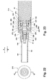
- Prewinder drive assembly 216 in its initial operating position shown in Figure 23 provides a clearance cavity 237 between mandrel drive member 226 and stall driver 236.
- the same tool 20 used in conjunction with retractable prewinder apparatus 10 can also be used with prewinder drive assembly 216 by threadably inserting tool 20 into engagement with extended length thread portion 238 of body 234 until contact between tool 20, stall stop member 232, and shoulder stop 233 of body 234 occurs.
- mandrel drive member 226 includes a drive end shaft 240 having drive end 224 extending outwardly therefrom.
- a drive end shaft through-bore 242 is created through drive end shaft 240 to slidably receive first pin 228.
- Drive end shaft 240 extends from a raised shoulder 244 which itself extends from a drive member flange 246.
- a drive member body 248 having a substantially tubular shape extends away from drive member flange 246.
- Each of the components of mandrel drive member 226 can be integrally and homogeneously created by a casting, machining, or molding process from a single material component.
- Drive member body 248 has a body diameter "G".
- a body end face 249 creates a free end of drive member body 248.
- An elongated aperture 250 is created parallel with a drive member longitudinal axis 252.
- the longitudinal axis of drive end shaft through-bore 242 intersects drive member longitudinal axis 252.
- a concave circumferential recess 254 can be created about a perimeter of drive end shaft 240.
- Elongated aperture 250 is a through-aperture created through opposing walls defining elongated aperture portions 250', 250".
- Body end face 249 is oriented substantially transverse to drive member longitudinal axis 252.
- stall sleeve 230 can be made from a generally tubular-shaped body 256 from a material such as a steel or polymeric material.
- a second elongated aperture 258 is created in tubular body 256 which is similarly sized with respect to elongated aperture 250 of mandrel drive member 226.
- a sleeve through-bore 260 extends throughout a length of stall sleeve 230.
- Second elongated aperture 258, similar to elongated aperture 250, is created as a through-aperture through opposing walls of tubular body 256 thereby defining first and second elongated aperture portions 258', 258".
- a threaded body end 262 is created at a free end of tubular body 256 having a tubular body end 263.
- First and second aperture portions 258', 258" are oriented in parallel with a stop member body longitudinal axis 264.
- sleeve through-bore 260 has a bore diameter "H” which is adapted to slidably receive the drive member body 248 of mandrel drive member 226.
- Body diameter "G” of mandrel drive member 226 is therefore adapted to provide a sliding fit with respect to bore diameter "H”.
- Sleeve tubular body 256 has a tubular body diameter "J”.
- stall stop member 232 includes a substantially tubular-shaped stop member body 265 having a continuously threaded perimeter 266. Threaded perimeter 266 is adapted to threadably engage with the extended length thread portion 238 of body 234. An internally threaded counterbore 268 and a clearance bore 270 are also created in interior spaces of stop member body 265. Clearance bore 270 has a clearance bore diameter "K”. Threaded counterbore 268 has a counterbore diameter "L" which is adapted to threadably receive the threaded body end 262 of stall sleeve 230.
- stall driver 236 can be made from a single homogeneous piece of material such as a metal or a polymeric material and includes a driver flange 272 having a flange diameter "M".
- a driver body 274 having a generally tubular shape extends from driver flange 272 and includes a body diameter "N" which is smaller than flange diameter "M”.
- a pin engagement aperture 276 is created as a through-aperture through opposing walls of driver body 274 defining first and second portions 276', 276" of pin engagement aperture 276. Pin engagement aperture 276 is created proximate to a driver body end 278. Pin engagement aperture 276 is sized to frictionally receive and retain second pin 239.
- a concave circumferential recess 280 can also be created about a perimeter of driver body 274 in parallel with a longitudinal axis of pin engagement aperture 276.
- the longitudinal axis of pin engagement aperture 276 is oriented substantially perpendicular to a longitudinal axis of driver body 274.
- a tool drive member receiving aperture 282 is adapted to receive a drive member (not shown) of tool 20.
- a plurality of aperture wall segments 284 defining a geometric shape matching the geometry of the tool engagement member are provided.
- prewinder drive assembly 216 can be as follows. From the initial position of prewinder drive assembly 216 shown in Figure 23 , drive end 224 of mandrel drive member 226 is engaged within slot 220 of mandrel flange end 222. Second pin 239 is frictionally received within pin engagement aperture 276 of stall driver 236 having opposed ends of second pin 239 freely positioned within each of elongated aperture 250 of mandrel drive member 226 and second elongated aperture 258 of stall sleeve 230.
- Rotation of stall driver 236 by operation of tool 20 co-rotates each of stall sleeve 230 and mandrel drive member 226 by contact between second pin 239 with walls of elongated aperture 250 and second elongated aperture 258.
- Rotation of mandrel drive member 226 thereby rotates mandrel portion 218 using the connection between drive end 224 and mandrel flange end 222.
- Stall stop member 232 is fixed and non-rotatably positioned with respect to body 234 by engagement between the threaded perimeter 266 of stall stop member 232 and extended length thread portion 238.
- Mandrel portion 218 (together with its second portion, not shown) operates to install a helically coiled insert 18 (not shown in this view) in the assembly installation direction "A".
- mandrel portion 218 is forced by displacement of its second mandrel portion (not shown) in the assembly contraction direction "B" which axially translates mandrel drive member 226 in the assembly contraction direction "B".
- the free ends of second pin 239 are repositioned within each of the elongated apertures 250 and second elongated apertures 258 as mandrel drive member 226 moves in the assembly contraction direction "B".
- a stall position is reached when the threaded body end 262 of stall sleeve 230 is fully threadably engaged with the threaded counterbore 268 of stall stop member 232 and the tubular body end 263 of stall sleeve 230 contacts the driver flange 272 of stall driver 236.
- the body end face 249 of mandrel drive member 226 is physically separated from the driver flange 272 of stall driver 236 to allow full threaded engagement of the coarse threads of the threaded body end 262 of stall sleeve 230 with the coarse threads of threaded counterbore 268.
- a length of second pin 239 can be controlled so that free ends of second pin 239 are retained within the extent of the wall thickness at first and second aperture portions 258', 258" of second elongated aperture 258 to preclude extension of second pin 239 into a body clearance cavity 288. This prevents contact of the free ends of second pin 239 from precluding rotation of the assembly.
- a cavity 286 between driver flange 272 of stall driver 236 and body 234 maintains clearance to the internal threads of body 234 permitting threaded engagement of stall stop member 232 with body 234.
- clutch tube end wall 96 also translates in the assembly contraction direction "B", creating a gap 290.
- translation of stall sleeve 230 in the assembly contraction direction "B" to reach the stall position creates a stall sleeve-to-flange clearance gap 292.
- a disengagement mechanism or prewinder drive assembly 300 includes a main body portion 302 having a body 304 and a sleeve 306 extending axially with respect to body 304.
- a tubular portion 308 similar to tubular portion 65 shown in Figure 1 extends axially from sleeve 306.
- Body 304 is adapted to engage with adapter 38 and prewinder portion 14 similar to body 42 of retractable prewinder apparatus 10.
- a clutch tube or retaining sleeve 310 is slidably disposed within the extending sleeve 306.
- a retaining sleeve cavity 312 is created in a stalled position of the prewinder drive assembly 300 shown in Figure 36 .
- the retaining sleeve 310 is slidably disposed in a direction "P" to create the retaining sleeve cavity 312.
- a receiving tube 314 is slidably received within retaining sleeve 310 and also within tubular portion 308. Sliding movement of retaining sleeve 310 concomitantly moves the receiving tube 314 in the direction "P".
- a mandrel first portion 315 (only partially shown) is connected to a mandrel extension 316 using a releasable connector 317 such as a pin.
- Mandrel extension 316 is slidably received through an opening of receiving tube 314 which includes an extension first end 318.
- a mandrel clip 320 is biased into contact about a perimeter of mandrel extension 316 to releasably connect the mandrel extension 316 to an inner body of a mandrel connecting member 322.
- a biasing member 321 such as a compression spring is positioned between mandrel connecting member 322 and receiving tube 314 to bias receiving tube 314 away from mandrel connecting member 322.
- Mandrel connecting member 322 is also slidably disposed within retaining sleeve 310. Axial displacement of the mandrel clip 320 therefore causes axial displacement of mandrel extension 316 as mandrel connecting member 322 is axially displaced.
- a drive member 324 To the right of mandrel connecting member 322 as viewed in Figure 36 is positioned a drive member 324.
- Drive member 324 engages the mandrell connecting member 322 similar to the connection of drive member 100 shown and described in reference to Figure 1 .
- First pin 102' releasably connects drive member 324 to retaining sleeve 310. Retaining sleeve 310 therefore co-rotates with rotation of drive member 324.
- a clutch sleeve or stall member 326 Positioned in slidable contact with drive member 324 is a clutch sleeve or stall member 326 which is in slidable contact with a drive member cylindrical body 328 of drive member 324.
- a clutch or stall stop 330 is similar in design and function to the stall stop member 232 shown and described and reference to Figure 34 .
- Stall stop 330 is threadably engaged on an interior threaded portion of main body portion 302 until stall stop 330 contacts a shoulder stop 332 created in main body portion 302.
- Stall stop 330 can provide a stop point for the maximum axial displacement of stall member 326 in direction "P".
- a flanged stall drive 334 having a stall drive tubular body 336 is slidably received in an interior diameter of drive member cylindrical body 328.
- Stall drive 334, stall member 326, and drive member 324 are together coupled using second pin 106' which is frictionally engaged in stall drive tubular body 336.
- Stall drive 334 is adapted to rotatably engage a tool drive member 338 extending from tool 20 such that rotation of tool drive member 338 co-rotates each of stall drive 334, stall member 326, drive member 324, mandrel connecting member 322, retaining sleeve 310, receiving tube 314, and mandrel extension 316.
- stall member 326 and stall stop 330 are translated in the direction "P" to a maximum extent to frictionally contact stall member 326, stall stop 330, and stall drive 334. This frictional contact acts to stall tool 20.
- Biasing members such as springs are used to prevent prewinder drive assembly 300 from binding in the stalled position.
- a first biasing member 339 such as a compression spring is positioned between and biases apart flanged stall drive 334 and drive member cylindrical body 328 of drive member 324.
- a drive member flange 340 of drive member 324 and a stall member flange 344 of stall member 326 are biased apart by a second biasing member 341 such as a flat wave spring, and a third biasing member 343 such as a flat wave spring is compressed between stall member flange 344 and 330 in the stall position. In the stalled position, biasing members 339 and 345 are compressed.
- a drive position of prewinder drive assembly 300 is shown.
- both drive member 324 and stall member 326 are displaced in a direction "Q" such that drive member flange 340 of drive member 324 and stall member flange 344 of stall member 326 move together in the direction "Q” also forcing retaining sleeve 310 to move in direction "Q” until retaining sleeve 310 contacts stop face 342 of extending sleeve 306.
- both stall drive tubular body 336 and stall member 326 are spatially separated from stall stop 330 and therefore are allowed to spin freely.
- retaining sleeve 310 and stop face 342 provides an axial stop for the axial displacement of drive member 324 in the direction "Q", while continuing to allow rotation of retaining sleeve 310 with respect to extending sleeve 306 and rotation of mandrel extension 316.
- Mandrel connecting member 322 will continue to axially displace in direction "Q” until mandrel connecting member 322 disengages from drive member 324.
- a clearance cavity 345 permits the continued axial displacement in the direction "Q" of mandrel connecting member 322 and mandrel extension 316 until the maximum insertion depth of helically coiled insert 18 is reached as described in reference to Figure 1 .
- Biasing member 321 is positioned within clearance cavity 345 as previously discussed to bias receiving tube 314 in the direction "Q" and away from mandrel connecting member 322.
- the second pin 106' which is engaged with stall drive tubular body 336 of stall drive 334, is axially displaceable in an elongated aperture 346 of drive member 324 and also in an elongated aperture 348 created in stall member 326 which is coaxially aligned with elongated aperture 346. Also in the drive position first biasing member 339 is partially compressed and second biasing member 341 is fully compressed, and a clearance space 347 between third biasing member 343 and stall stop 330 allows full expansion of third biasing member 343.
- retaining sleeve 310 includes a tubular body 350 having a pin retaining aperture 352 oriented perpendicular to tubular body 350.
- pin retaining aperture 352 is adapted to frictionally receive first pin 102'.
- a body end wall 354 extends radially inwardly with respect to tubular body 350 to create an inner flange adapted to contact a corresponding outwardly directed radial flange of receiving tube 314 shown in Figure 36 .
- receiving tube 314 includes a receiving tube body 356 which is generally tubular in shape having a raised radially outwardly extending raised radial flange 358 positioned at a first end thereof.
- a tube body end wall 360 is created at an opposite second end of receiving tube body 356 with respect to raised radial flange 358.
- the tube body end wall 360 extends radially inwardly from receiving tube body 356 and is adapted to slidably receive the mandrel extension 316 in a through-aperture 362 defined by tube body end wall 360.
- An inner circumferential slot 363 can also be provided on an inner wall of receiving tube body 356.
- the raised radial flange 358 is adapted to contact body end wall 354 of retaining sleeve 310 such that axial displacement of retaining sleeve 310 will coaxially extend receiving tube 314.
- mandrel extension 316 provides extension first end 318 and an extension second end 364.
- a neck portion 366 is created by circumferentially removing material from mandrel extension 316 to delineate the extension first end 318 from the extension second end 364.
- Neck portion 366 with further reference to Figure 36 is adapted to receive the mandrel clip 320.
- mandrel extension 316 is provided with multiple facetted perimeter faces 368 to create a geometric shape such as a hexagon or an octagon.
- the facetted perimeter faces 368 are adapted to translate rotational torque as mandrel extension 316 is rotated.
- a chamfered end 370 can also be provided at a free end of extension first end 318 and similarly if desired to a free end of extension second end 364 (not shown) to permit sliding displacement of mandrel extension 316 during installation or removal.
- mandrel connecting member 322 includes a connecting member tubular body 372 having a flange end 374 radially extending outwardly with respect to connecting member tubular body 372 and defining a first end of connecting member tubular body 372.
- a pin receiving aperture 376 is perpendicularly oriented with respect to connecting member tubular body 372.
- a hex drive aperture 378 is provided to slidingly receive the facetted perimeter faces 368 shown and described with reference to Figure 40 of the mandrel extension 316. Rotation of mandrel connecting member 322 therefore functions to rotate mandrel extension 316.
- a slot 380 is created perpendicularly to flange end 374 and connecting member tubular body 372 and functions similarly to slot 101 shown and described in reference to Figure 1 .
- drive member 324 includes elongated apertures 346, 346' (aperture 346' is oppositely positioned and not visible in this view) created through drive member cylindrical body 328. Elongated apertures 346, 346' at one end abut the drive member flange 340.
- a raised shoulder 382 extends substantially transversely with respect to a flange end wall 383 of drive member flange 340.
- a drive end shaft through-bore 384 is created perpendicularly with respect to raised shoulder 382 which is adapted to frictionally receive first pin 102' shown and described in reference to Figure 36 .
- a drive end 386 is created as an extension from drive end wall 388 of raised shoulder 382. With further reference to Figure 41 and Figure 36 , drive end 386 is adapted to be received in the slot 380 of mandrel connecting member 322 such that rotation of drive member 324 co-rotates mandrel connecting member 322.
- the stall member 326 includes elongated apertures 348, 348' created in opposing wall portions of drive member cylindrical body 328. One end of each of the elongated apertures 348, 348' abuts the stall member flange 344 which is positioned at a first end of stall member 326.
- An outside diameter threaded body end 390 is created proximate to an opposed second end of drive member cylindrical body 328.
- An inner body raised portion 392 provides additional wall thickness through drive member cylindrical body 328 for the elongated apertures 348, 348'.
- a reduced diameter body end 394 defines the free end portion of the second end of drive member cylindrical body 328.
- stall stop 330 includes an outside diameter threaded body 396 and includes an inner diameter threaded body portion 398 proximate a first end thereof.
- Inner diameter threaded body portion 398 defines an aperture 400 and is adapted to threadably receive the outside diameter threaded body end 390 of stall member 326.
- the outside diameter threaded body 396 is adapted to be threadably connected to the interior threaded portion of main body portion 302.
- a stop face 402 of stall stop 330 is created at an interior facing end of threaded body portion 398. Stop face 402 is oriented substantially transverse to a longitudinal axis of cylindrical threaded body 396 defined by the aperture 400, and extends inwardly with respect to a body inner wall 404, and has a diameter larger than a diameter of aperture 400.
- the stall drive 334 includes opposed pin engagement apertures 406, 406' which are oriented transversely with respect to stall drive tubular body 336. Pin engagement apertures 406, 406' are adapted to frictionally engage second pin 106' as shown and described in reference to Figure 36 .
- a hex drive aperture 408 is longitudinally created through stall drive tubular body 336 and is adapted to receive tool drive member 338 shown and described in reference to Figure 36 .
- a radial flange 410 extends outwardly and transversely with respect to stall drive tubular body 336 and as shown in reference to Figure 36 creates a stop surface for stall member 326 in the stalled position of prewinder drive assembly 300.
- the retractable prewinders of the present disclosure offer several advantages. By adapting the prewinder portion 14 for slidable insertion into body 42 in lieu of fixing the prewinder portion 14 to the body 42, the axial displacement of prewinder portion 14 can be used to accurately control a depth of insertion of the helically coiled insert 18. By providing threaded insert 61 which axially translates by rotation of adapter 38 and is therefore infinitely adjustable, an unlimited number of positive stop positions for prewinder portion 14 are created.
Landscapes
- Engineering & Computer Science (AREA)
- Mechanical Engineering (AREA)
- Hand Tools For Fitting Together And Separating, Or Other Hand Tools (AREA)
- Pressure Welding/Diffusion-Bonding (AREA)
- Wire Processing (AREA)
Abstract
Description
- The present disclosure relates to devices and methods for installing helically coiled inserts.
- This section provides background information related to the present disclosure which is not necessarily prior art.
- Helically coiled wire inserts both of tanged or tangless design can be inserted using hand tools, electrical, battery powered, or pneumatic tools. Coarse thread size inserts, such as thread sizes 4-40, 6-32, 10-24, ¼-20, etc., are relatively stiff or rigid and can be installed using a predetermined mandrel. Fine thread size inserts, however, such as for thread sizes 4-48, 6-40, 8-36, 10-32, ¼-28, etc., are commonly flexible and may not retain their shape during installation. Fine thread size inserts therefore commonly require a pre-winder to be used in conjunction with a mandrel to help reduce the outside diameter of the inserts and to align the coils of the wire insert to the correct pitch so they can be more easily installed into a tapped aperture of for example a work piece or fastener body. Pre-winders are known for use with hand tools, electric, battery operated, and/or pneumatic power tools, however known pre-winders for these tools for the installation of helically coiled inserts often also require spacers or shims to accommodate differences in insert length or installation depth. Installation of spacers or shims normally requires stocking multiple sizes of parts, with associated additional part costs, time delay in their installation, and defective parts which do not receive the properly installed insert.
- The installation of spacers or shims commonly requires disassembly of the tool or prewinder followed by installation of the necessary spacers or shims. The disassembly time further adds costs and time delay to completion of the component. The tool must then be reassembled and tested with the shims and spacers installed. If proper installation depth is not achieved, the process must be repeated until the appropriate shims or inserts are installed to provide the desired coil installation depth. This repetition further increases costs and time delays. An additional problem of know installation tools is providing a positive, repeatable stall position for the motor when the coil has reached an intended installation depth which can cause tool jamming.
- This section provides a general summary of the disclosure, and is not a comprehensive disclosure of its full scope or all of its features.
- According to several embodiments of a retractable prewinder assembly of the present disclosure, a prewinder apparatus attached to a drive tool for installation of a helical coil insert includes a body connected to the drive tool. An adapter rotatable with respect to the body is releasably connected to the body at operator selected ones of a plurality of rotated positions. A prewinder portion is slidably displaceable into and out of the body coaxial to a longitudinal axis of the body and the adapter, and biased by a first biasing member toward an extended position. A mandrel is axially extensible from the prewinder portion when the prewinder portion is slidably displaced into the body against a biasing force of the first biasing member. The mandrel is adapted to engage the helical coil insert to rotatably insert the coil insert.
- According to other embodiments, a prewinder apparatus selectively attachable to a drive tool for installation of a helical coil insert includes a body connected to the drive tool. An adapter is rotatable with respect to the body and is releasably connected to the body at operator selected ones of a plurality of rotated positions. A prewinder portion is slidably displaceable into and out of the body coaxial to a longitudinal axis of the body and the adapter. The prewinder portion is slidably translatable into the body until a fastener engaged with the prewinder portion contacts a stop member defining a predetermined depth of insertion for the helical coil insert. A mandrel is axially extensible from the prewinder portion when the prewinder portion is slidably displaced into the body. The mandrel is adapted to engage the helical coil insert to rotatably insert the helical coil insert.
- According to still other embodiments, a prewinder apparatus attached to a drive tool for installation of a helical coil insert includes a clutch assembly having a stall sleeve having a plurality of inner cavity threads. A stall coupling is both slidably and threadably receivable within an inner bore of the stall sleeve and further includes a plurality of outer perimeter threads adapted to be threadably engaged with the plurality of inner cavity threads of the stall sleeve. A drive socket is connected for rotation to the drive tool and axially translatable within the stall coupling. Upon full threaded engagement of the outer perimeter threads with the inner cavity threads an end face of the stall coupling contacts a wall of the stall sleeve preventing further axial translation of the stall coupling to frictionally stall the drive tool.
- According to further embodiments, a stall assembly includes a stall stop member threadably engaged with the body. A stall sleeve is slidably received in the stall stop member. A mandrel drive member having a drive end is adapted to releasably engage with the slot to rotate the mandrel, the mandrel drive member slidably received in the stall sleeve. A stall driver slidably is received within an inner diameter portion of mandrel drive member and having a radially extending flange. A fastener frictionally engaged with the stall driver and freely received in an elongated aperture of each of the stall sleeve and the mandrel drive member is adapted to co-rotate the stall sleeve and the mandrel drive member when the stall driver is rotated by the drive tool. When full threaded engagement of the stall sleeve with the stall stop member occurs, a tubular body end of the stall sleeve contacts the radially extending flange of the stall driver to stall the drive tool.
- According to still further embodiments, a prewinder apparatus attached to a drive tool for installation of a helical coil insert includes a body connected to the drive tool, and a mandrel axially extensible from the body and having a mandrel flange end including a slot. The mandrel is adapted to engage the helical coil insert to rotatably insert the coil insert. A drive member is releasably engaged to the mandrel and adapted to rotate the mandrel. A stall assembly includes: a stall stop member threadably engaged with the body; a stall sleeve slidably received in the stall stop member; a mandrel drive member having a drive end adapted to releasably engage with the slot to rotate the mandrel, the mandrel drive member slidably received in the stall sleeve; a stall driver slidably received within an inner diameter portion of mandrel drive member and having a radially extending flange; and a fastener frictionally engaged with the stall driver and freely received in an elongated aperture of each of the stall sleeve and the mandrel drive member adapted to co-rotate the stall sleeve and the mandrel drive member when the stall driver is rotated by the drive tool. When full threaded engagement of the stall sleeve with the stall stop member occurs a tubular body end of the stall sleeve contacts the radially extending flange of the stall driver to stall the drive tool.
- According to other embodiments, a prewinder apparatus attached to a drive tool for installation of a helical coil insert includes a body connected to the drive tool. A prewinder portion is movable with respect to the body. A mandrel axially extensible from the prewinder portion is adapted to engage the helical coil insert to rotatably insert the coil insert. A drive system is adapted to rotate the mandrel and translate the mandrel in each of an installation direction and a retraction direction. A disengagement mechanism is adapted to disengage the mandrel from the drive system when the helical coil insert reaches an installed position by translation of the mandrel in the installation direction. A stall mechanism is adapted to stop rotation of the mandrel when the mandrel is retracted in the retraction direction to a fully retracted position.
- Further areas of applicability will become apparent from the description provided herein. The description and specific examples in this summary are intended for purposes of illustration only and are not intended to limit the scope of the present disclosure.
- The drawings described herein are for illustrative purposes only of selected embodiments and not all possible implementations, and are not intended to limit the scope of the present disclosure.
-
Figure 1 is a cross sectional front elevational view of a retractable prewinder assembly of the present disclosure; -
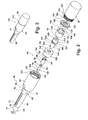
Figure 2 is a front elevational perspective view of a tool and driving sleeve of the present disclosure; -
Figure 3 is a front elevational assembly view of the tool/prewinder assembly ofFigure 2 ; -
Figure 4 is a bottom plan view of an adapter from the assembly ofFigure 3 ; -
Figure 5 is a top plan view of the adapter ofFigure 4 ; -
Figure 6 is an end elevational view of the adapter ofFigure 4 viewed from left to right inFigure 4 ; -
Figure 7 is a cross sectional front elevational view taken at section 7 ofFigure 6 ; -
Figure 8 is a front left perspective view of a drive member from the assembly ofFigure 3 ; -
Figure 9 is a cross sectional front elevational view taken atsection 9 ofFigure 10 ; -
Figure 10 is an end elevational view of the drive member ofFigure 8 ; -
Figure 11 is a front elevational view ofArea 11 ofFigure 9 ; -
Figure 12 is a front elevational view of a drive coupling from the assembly ofFigure 3 ; -
Figure 13 is an end elevational view of the drive coupling ofFigure 12 viewed from right to left inFigure 12 ; -
Figure 14 is a front elevational view of a stall coupling from the assembly ofFigure 3 ; -
Figure 15 is an end elevational view of the stall coupling ofFigure 14 viewed from left to right inFigure 14 ; -
Figure 16 is a front elevational view of a stall sleeve from the assembly ofFigure 3 ; -
Figure 17 is an end elevational view of the stall sleeve ofFigure 16 viewed from right to left inFigure 16 ; -
Figure 18 is a cross sectional front elevational view of the retractable prewinder assembly ofFigure 1 modified to show displacement during an intermediate coil installation step; -
Figure 19 is the cross sectional front elevational view of the retractable prewinder assembly ofFigure 18 further modified to show prewinder portion displacement following completion of coil installation; -
Figure 20 is the cross sectional front elevational view of the retractable prewinder assembly ofFigure 19 further modified to show second clutch operation in a stall condition; -
Figure 21 is the cross sectional front elevational view of the retractable prewinder assembly ofFigure 20 further modified to show disengagement of the drive member from the drive socket disengaging rotational drive to the mandrel; -
Figure 22 is an end elevational view of a prewinder drive assembly of another embodiment of the present disclosure adapted for stall operation; -
Figure 23 is a cross sectional front elevational view taken atsection 23 ofFigure 22 ; -
Figure 24 is a top plan view of a drive member of the prewinder drive assembly ofFigure 23 ; -
Figure 25 is a front elevational view of the drive member ofFigure 24 ; -
Figure 26 is a front right perspective view of a stall sleeve of the prewinder drive assembly ofFigure 23 ; -
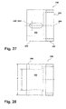
Figure 27 is a top plan view of the stall sleeve ofFigure 26 , -
Figure 28 is a front elevational view of the stall sleeve ofFigure 26 ; -
Figure 29 is a top plan view of a stall stop member of the prewinder drive assembly ofFigure 23 ; -
Figure 30 is a front elevational view of the stall stop member ofFigure 29 ; -
Figure 31 is a top plan view of a stall driver of the prewinder drive assembly ofFigure 23 ; -
Figure 32 is a front elevational view of the stall driver ofFigure 31 ; -
Figure 33 is an end elevational view of the prewinder drive assembly ofFigure 23 in a stalled condition; -
Figure 34 is a cross sectional front elevational view taken atsection 34 ofFigure 33 ; -
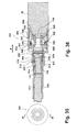
Figure 35 is an end elevational view of another embodiment of a prewinder drive assembly of the present disclosure; -
Figure 36 is a cross sectional front elevational view taken atsection 36 ofFigure 35 , showing the drive assembly in a stalled position; -
Figure 37 is the cross sectional front elevational view ofFigure 36 showing the drive assembly in a drive position; -
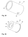
Figure 38 is a front perspective view of a retaining sleeve for the prewinder drive assembly ofFigure 35 ; -
Figure 39 is a front perspective view of a retainer for the prewinder drive assembly ofFigure 35 ; -
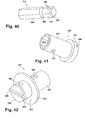
Figure 40 is a front perspective view of a mandrel extension for the prewinder drive assembly ofFigure 35 ; -
Figure 41 is a front perspective view of a connecting member for the prewinder drive assembly ofFigure 35 ; -
Figure 42 is a front perspective view of a drive member for the prewinder drive assembly ofFigure 35 ; -
Figure 43 is a front perspective view of a clutch sleeve for the prewinder drive assembly ofFigure 35 ; -
Figure 44 is a front perspective view of a clutch stop for the prewinder drive assembly ofFigure 35 ; and -
Figure 45 is a front perspective view of a stall drive for the prewinder drive assembly ofFigure 35 . - Corresponding reference numerals indicate corresponding parts throughout the several views of the drawings.
- Example embodiments will now be described more fully with reference to the accompanying drawings.
- Example embodiments are provided so that this disclosure will be thorough, and will fully convey the scope to those who are skilled in the art. Numerous specific details are set forth such as examples of specific components, devices, and methods, to provide a thorough understanding of embodiments of the present disclosure. It will be apparent to those skilled in the art that specific details need not be employed, that example embodiments may be embodied in many different forms and that neither should be construed to limit the scope of the disclosure. In some example embodiments, well-known processes, well-known device structures, and well-known technologies are not described in detail.
- The terminology used herein is for the purpose of describing particular example embodiments only and is not intended to be limiting. As used herein, the singular forms "a", "an" and "the" may be intended to include the plural forms as well, unless the context clearly indicates otherwise. The terms "comprises," "comprising," "including," and "having," are inclusive and therefore specify the presence of stated features, integers, steps, operations, elements, and/or components, but do not preclude the presence or addition of one or more other features, integers, steps, operations, elements, components, and/or groups thereof. The method steps, processes, and operations described herein are not to be construed as necessarily requiring their performance in the particular order discussed or illustrated, unless specifically identified as an order of performance. It is also to be understood that additional or alternative steps may be employed.
- When an element or layer is referred to as being "on", "engaged to", "connected to" or "coupled to" another element or layer, it may be directly on, engaged, connected or coupled to the other element or layer, or intervening elements or layers may be present. In contrast, when an element is referred to as being "directly on," "directly engaged to", "directly connected to" or "directly coupled to" another element or layer, there may be no intervening elements or layers present. Other words used to describe the relationship between elements should be interpreted in a like fashion (e.g., "between" versus "directly between," "adjacent" versus "directly adjacent," etc.). As used herein, the term "and/or" includes any and all combinations of one or more of the associated listed items.
- Although the terms first, second, third, etc. may be used herein to describe various elements, components, regions, layers and/or sections, these elements, components, regions, layers and/or sections should not be limited by these terms. These terms may be only used to distinguish one element, component, region, layer or section from another region, layer or section. Terms such as "first," "second," and other numerical terms when used herein do not imply a sequence or order unless clearly indicated by the context. Thus, a first element, component, region, layer or section discussed below could be termed a second element, component, region, layer or section without departing from the teachings of the example embodiments.
- Spatially relative terms, such as "inner," "outer," "beneath", "below", "lower", "above", "upper" and the like, may be used herein for ease of description to describe one element or feature's relationship to another element(s) or feature(s) as illustrated in the figures. Spatially relative terms may be intended to encompass different orientations of the device in use or operation in addition to the orientation depicted in the figures. For example, if the device in the figures is turned over, elements described as "below" or "beneath" other elements or features would then be oriented "above" the other elements or features. Thus, the example term "below" can encompass both an orientation of above and below. The device may be otherwise oriented (rotated 90 degrees or at other orientations) and the spatially relative descriptors used herein interpreted accordingly.
- Referring to
Figure 1 , aretractable prewinder apparatus 10 includes a disengagement mechanism orprewinder drive assembly 12 having aprewinder portion 14 releasably connected to theprewinder drive assembly 12. Amandrel 16 axially disposed inprewinder drive assembly 12 and extending throughprewinder portion 14 is rotated by theprewinder drive assembly 12 to insert a helically coiledinsert 18. Motive drive force to rotate portions of theprewinder drive assembly 12 includingmandrel 16 can be provided using atool 20 such as an electric motor powered for example by a battery or 110 volt AC power, a pneumatic drive such as air or hydraulic fluid, or similar drive device. -
Prewinder portion 14 includes a predominantly tubular shapedprewinder body 22 having alongitudinal cavity 24 coaxially aligned with a threadedlongitudinal aperture 26. Threadedlongitudinal aperture 26 is adapted to threadably receive a threadedbody portion 28 ofmandrel 16. The helically coiledinsert 18 is positioned within aninsert receiving cavity 30 prior to rotation of themandrel 16. Acoil engagement end 32 ofmandrel 16 engages the helically coiledinsert 18 to rotatably direct the helically coiledinsert 18 into a coildiameter reducing aperture 34 created in acoil reducing member 36 which defines a free end ofprewinder portion 14. Coildiameter reducing aperture 34 has a predefined aperture size to suit installation of the helically coiledinsert 18 in one of a plurality of panel apertures which will be described in reference toFigure 18 . -
Prewinder portion 14 is axially slidably received in anadapter 38 within afirst adapter portion 39.First adapter portion 39 is homogeneously and integrally connected to asecond adapter portion 40 withfirst adapter portion 39 having a smaller outside diameter thansecond adapter portion 40.Adapter 38 is in turn releasably connected to abody 42 using at least one and according to several embodiments a plurality offasteners 44, 44'.Fasteners 44, 44' are threadably inserted through fastener receiving apertures created insecond adapter portion 40 proximate to abody end wall 46. Ashank 48 of each of thefasteners 44, 44' is received in acircumferential slot 50 created in an extendingsleeve 51 ofbody 42. By loosening thefasteners 44, 44' with theshank 48 of each of thefasteners 44, 44' partially retained in thecircumferential slot 50, theadapter 38 can be rotated with respect tobody 42 while theshanks 48 slide withincircumferential slot 50.Fasteners 44, 44' can then be tightened to engage theirshanks 48 in contact with an end wall ofcircumferential slot 50 to frictionally engagesecond adapter portion 40 tobody 42. - The components of retractable
prewinder apparatus 10 are generally arranged with respect to alongitudinal axis 52 such thatmandrel 16 is rotatable and axially translated coaxial withlongitudinal axis 52. A first biasingmember 54 is positioned within acylinder portion 56 ofbody 42. According to several embodiments first biasingmember 54 is a compression spring made for example of a spring steel material. An internal diameter defined bycylinder portion 56 is sized to slidably receive the outside diameter ofprewinder body 22. First biasingmember 54 allows axial sliding ofprewinder portion 14 in each of a assembly installation direction "A" and a assembly contraction direction "B" oppositely directed from assembly installation direction "A". First biasingmember 54 biases prewinderportion 14 in assembly installation direction "A". - First biasing
member 54 is oriented to contact each of aprewinder end wall 58 ofprewinder body 22 and acontact wall 60 defining an end wall ofcylinder portion 56. A threadedinsert 61 having aninsert body 62 is translatable parallel tolongitudinal axis 52 such that an insertlongitudinal axis 63 oriented substantially transverse tolongitudinal axis 52 can be positioned at the discretion of an operator of retractableprewinder apparatus 10.Insert body 62 is axially movable while being prevented from rotation within anadapter portion cavity 64.Adapter portion cavity 64 is created by removal of (or cast or molded without) a portion of the material of atubular portion 65 ofbody 42. As previously noted, iffasteners 44, 44' are loosened withshanks 48 slidably received withincircumferential slot 50, the insertlongitudinal axis 63 of threadedinsert 61 can be axially repositioned by rotatingadapter 38 with respect tobody 42. To translate threadedinsert 61, threadedinsert 61 includes a plurality ofinsert threads 66 which threadably engage a plurality ofinsert engagement threads 68 created on an internal diameter offirst adapter portion 39. Becauseinsert body 62 is non-rotatably retained withinadapter portion cavity 64, manual rotation ofadapter 38 axially displacesinsert body 62 usinginsert threads 66 by threaded engagement withinsert engagement threads 68 offirst adapter portion 39. - Threaded
insert 61 is used as a stop member which is axially and selectively positioned to control a dept of insertion of helically coiledinsert 18. A stop fastener 70 includes afastener head 72 which contacts aninsert face 74 of threadedinsert 61 to stop axial displacement ofprewinder portion 14. An operator selectable distance betweenfastener head 72 and insertface 74 with theprewinder portion 14 in the fully extended position shown inFigure 1 defines a prewinder depth of insertion "C". Prewinder depth of insertion "C" is controlled by displacing the insertlongitudinal axis 63 of threadedinsert 61 by rotation ofadapter 38 as described above. Stop fastener 70 further includes aninsert shank 76 which is threadably received in a threaded bore 78 created inprewinder body 22. Contact betweenfastener head 72 of stop fastener 70 also provides an extension stop defining the fully extended position ofprewinder portion 14 in the assembly installation direction "A" by contact betweenfastener head 72 and anend wall 79 offirst adapter portion 39.Fastener head 72 is sized to be slidably received withinadapter portion cavity 64. - A
ball 80 made for example from a metal or polymeric material is biased into engagement with one of a plurality ofdetent cavities 82 circumferentially created about extendingsleeve 51 ofbody 42.Ball 80 is received in aball cavity 84 created insecond adapter portion 40. A biasingring 86 made for example of a spring steel material is positioned in a circumferential slot created insecond adapter portion 40 and allowsball 80 to deflect outwardly with respect to extendingsleeve 51 in-between the various positions of thedetent cavities 82. The detent cavities 82 are located at predetermined positions about the circumference of extendingsleeve 51. According to several embodiments, movement ofball 80 to successive ones ofdetent cavities 82 corresponds with a predetermined increment such as 0.01 in (0.25 mm) of axial displacement for threadedinsert 61. Once threadedinsert 61 is positioned as desired by rotation ofadapter 38 untilball 80 is received in one of thedetent cavities 82, thefasteners 44, 44' are fully engaged such that theshanks 48 of thefasteners 44, 44' frictionally contact thecircumferential slot 50 to temporarily and releasably fix the position ofadapter 38 with respect tobody 42. Once fixed, prewinder depth of insertion "C" is retained and repeatable for installation of multiple helically coiled inserts 18. -
Prewinder drive assembly 12 further includes a disengagement mechanism such as a firstclutch assembly 88. Firstclutch assembly 88 includes aclutch tube 90 slidably received inbody 42. Amandrel flange end 92 is slidably received within an inner bore ofclutch tube 90 such thatmandrel flange end 92 withmandrel 16 is coaxially aligned withlongitudinal axis 52. Asecond biasing member 94 is positioned within the bore ofclutch tube 90 and contacts at opposite ends themandrel flange end 92 and a clutchtube end wall 96 ofclutch tube 90. Axial displacement ofmandrel 16 andmandrel flange end 92 is therefore provided within the bore ofclutch tube 90. Adrive end 98 similar in shape to the slotted end of a slotted screwdriver extends from adrive member 100. Driveend 98 is received within aslot 101 created inmandrel flange end 92 such that rotation ofdrive member 100 operates toco-rotate mandrel 16.Drive member 100 is releasably coupled toclutch tube 90 using a fastener such as afirst pin 102 slidably received through opposed apertures ofclutch tube 90 and a corresponding aperture ofdrive member 100. -
Drive member 100 is similarly coupled to adrive coupling 104 using a fastener such as asecond pin 106.Drive coupling 104 provides adrive socket 108 which slidably receives a male extending drive member (not shown) extending fromtool 20. Asocket mating connection 110 is created indrive socket 108 which is geometrically-shaped to correspond to the geometric shape of the drive member extending fromtool 20. Common shapes used for this purpose include heptagon or hexagon shaped drive members. -
Prewinder drive assembly 12 further includes a stall mechanism such as a secondclutch assembly 112. Secondclutch assembly 112 includes astall coupling 114 which has each of athird biasing member 116 and afourth biasing member 118 positioned within thestall coupling 114. Anengagement flange 120 radially extending outwardly fromdrive socket 108 defines a contact wall for each of the third and fourth biasingmembers keys 121 integrally extend from an outer perimeter ofengagement flange 120. The function of the extendingkeys 121 will be described in reference toFigures 3 ,13 , and15 . -
Stall coupling 114 is both slidably and threadably receivable within an inner bore of astall sleeve 122. Atubular insert 123 can also be provided withinstall coupling 114 to maintain separation between the third and fourth biasingmembers Stall coupling 114 can include a plurality of left handouter perimeter threads 124 which are threadably engaged with a plurality of left handinner cavity threads 126 provided withstall sleeve 122. A perimeterradial flange 128 radially extending outwardly fromstall sleeve 122 abuts against acontact face 130 ofbody 42 to fix the position ofstall sleeve 122 withinbody 42. A plurality ofinner body threads 132 are created proximate to a body/tool engagement end 133 ofbody 42.Inner body threads 132 are adapted to threadably receive corresponding threads oftool 20 to threadingly engagetool 20 tobody 42, having perimeterradial flange 128 ofstall sleeve 122 contacting bothcontact face 130 and a threaded insertion end oftool 20. - Second
clutch assembly 112, and inparticular stall coupling 114, are slidably received within the inner cavity ofstall sleeve 122 untilouter perimeter threads 124 threadably engageinner cavity threads 126. Thereafter, further rotation ofdrive socket 108 pullsdrive socket 108 in the assembly contraction direction "B" until anend face 134 ofstall coupling 114 contacts aninterior wall face 136 ofstall sleeve 122 preventing further translation ofstall coupling 114 and thereby frictionally stalling further rotation oftool 20. - Installation of helically coiled
insert 18 is accomplished by translating bothtool 20 with the components of retractableprewinder apparatus 10 coaxially alonglongitudinal axis 52 in the assembly installation direction "A" until contact occurs betweencoil reducing member 36 at aprewinder contact end 138 with a panel. Further translation of retractableprewinder apparatus 10 in the assembly installation direction "A" together with operation oftool 20 causesprewinder portion 14 to move inwardly in the assembly contraction direction "B" which will be described in greater detail in reference toFigures 18 and19 . - Referring to
Figure 2 , a tool and drivingsleeve assembly 140 includestool 20 threadably coupled to body/tool engagement end 133 ofbody 42.Tubular portion 65 and extendingsleeve 51 extend oppositely with respect totool 20. - Referring to
Figure 3 , the components of tool and drivingsleeve assembly 140 are shown prior to assembly. Theadapter portion cavity 64 oftubular portion 65 extends through a wall thickness oftubular portion 65.Fastener head 72 is slidably received withinadapter portion cavity 64.Adapter 38 is not shown for clarity. A prewinder fullyextended position 142 ofprewinder portion 14 is shown. Individual ones of thedetent cavities 82, 82' positioned about extendingsleeve 51 can be located closer or further away from each other depending on a total quantity ofdetent cavities 82 selected.Mandrel 16 can further be divided into sections, for example having abody tube 143 connected tomandrel flange end 92 and a second portion (not shown) which extends throughprewinder portion 14. - A
pin aperture 144 can be provided at a free end ofbody tube 143 to pin the second portion ofmandrel 16 for extension throughprewinder portion 14.Mandrel 16 andmandrel flange end 92 are slidably disposed within a clutch tube throughbore 145 ofclutch tube 90.Clutch tube 90 can further include oppositely positioned first and second clutch tube pin bores 146, 147 adapted to receive a pin for connectingclutch tube 90 to drivemember 100.Drive member 100 can further include a first drive member pin bore 148 which is coaxially aligned with opposed internally located first and second semi-circular pin bores 149, 149' (only first semi-circular pin bore 149 is clearly visible). Thedrive end 98 ofdrive member 100 can engage with theslot 101 ofmandrel 16 to rotatemandrel 16, or, driveend 98 can disengage fromslot 101 as the mandrel threadably extends fromprewinder portion 14 when helically coiledinsert 18 reaches its predetermined set or installation depth, disengagingdrive end 98 fromslot 101. -
Drive member 100 can further include a drive member bore 150 which is adapted to slidably receive a firstdrive coupling portion 151 ofdrive coupling 104. With firstdrive coupling portion 151 inserted through drive member bore 150, a pin is slidably insertable through first drive member pin bore 148 and each of first and second semi-circular pin bores 149, 149', as well as through a drive coupling pin bore 152 created through firstdrive coupling portion 151. With the pin thus inserted, the first and second semi-circular pin bores 149, 149' ofdrive member 100 allow a degree of freedom of displacement for the pin relative to the first and second semi-circular pin bores 149, 149' to permitdrive coupling 104 to disengage fromdrive member 100 under certain operating conditions.Drive coupling 104 further includes aperimeter surface 153 ofengagement flange 120. The plurality of extendingkeys 121 extend radially outward with respect toperimeter surface 153. -
Stall coupling 114 includes aninner bore surface 154 into which is machined or formed a plurality oflongitudinal slots 155, 155' which are oriented parallel tolongitudinal axis 52. Individual ones of the plurality of extendingkeys 121 are received in thelongitudinal slots 155.Longitudinal slots 155 allow axial sliding motion ofdrive coupling 104 with respect to stallcoupling 114 while insertion of the extendingkeys 121 into thelongitudinal slots 155 translates the rotational motion ofdrive coupling 104 to stallcoupling 114. Theouter perimeter threads 124 ofstall coupling 114 are initially slidably received within a stall sleeve bore 156 ofstall sleeve 122. When thedrive socket 108 ofdrive coupling 104 is received in stall sleeve bore 156, the drive member (not shown) oftool 20 is slidably received insocket mating connection 110 ofdrive coupling 104, permitting the rotational drive torque oftool 20 to be transferred to drivecoupling 104. - The assembly of tool and driving
sleeve assembly 140 is completed when the perimeterradial flange 128 ofstall sleeve 122 abutscontact face 130. Aflange perimeter surface 158 of perimeterradial flange 128 freely slides intobody 42 having clearance with respect toinner body threads 132. Atool end 160 oftool 20 contacts an opposite face of perimeterradial flange 128 when a plurality oftool threads 162 are threadably engaged withinner body threads 132 until thetool contact end 163 oftool 20 contacts body/tool engagement end 133 ofbody 42. - Referring to
Figure 4 and again toFigure 1 ,body 42 includestubular portion 65 extending oppositely with respect to body/tool engagement end 133.Tubular portion 65 is created as a hollow tube-shaped extension ofbody 42 having a diameter smaller than a diameter of extendingsleeve 51 which is integrally and homogeneously connected tobody 42. The plurality ofdetent cavities sleeve 51. The quantity ofdetent cavities 82 can be varied and according to several embodiments eachsuccessive detent cavity 82 represents a linear displacement of the threadedinsert 61 of approximately 0.010 in (0.25 cm) asball 80 is partially received in successive ones of thedetent cavities 82. Thecircumferential slot 50 is created by forming or machining material of extendingsleeve 51. Amain body portion 161 is also tubular in shape and provides body/tool engagement end 133.Main body portion 161 can have a diameter larger than a diameter of bothtubular portion 65 and extendingsleeve 51. - Referring to
Figure 5 , a flat 164 is machined or formed parallel to alongitudinal axis 165 oftubular portion 65. Removal of material or formation of flat 164 creates the elongatedadapter portion cavity 64. Acavity end wall 166 is created to provide a positive stop end foradapter portion cavity 64 to retain the structural integrity oftubular portion 65.Cavity end wall 166 is positioned proximate to anend face 167 oftubular portion 65. - Referring to
Figure 6 , the diameter relationships oftubular portion 65, the increaseddiameter extending sleeve 51, and the largest diameter ofmain body portion 161 are evident. The flat 164 can be positioned at any perimeter portion oftubular portion 65 at the discretion of the manufacturer. - Referring
Figure 7 and again toFigure 1 ,contact wall 60 creates a division betweencylinder portion 56 oftubular portion 65 and a clutch tube receiving bore 168 created in extendingsleeve 51. Clutchtube receiving bore 168 opens into a clutch assembly receiving bore 170 created inmain body portion 161 adapted to receive secondclutch assembly 112. - Referring to
Figure 8 ,drive member 100 includes acylindrical body 172 having first drive member pin bore 148 created transversely thereto. A raisedshoulder 174 extends from anend wall 175. Adrive end shaft 176 having a diameter smaller than a diameter of raisedshoulder 174 extends integrally and homogeneously fromend wall 175. A drive end shaft through-bore 178 is oriented substantially parallel to first drive member pin bore 148 and is oriented transverse to a longitudinal axis ofdrive member 100. Driveend 98 is created at a free end ofdrive end shaft 176. According to several embodiments drivemember 100 can be made from a metal including steel or stainless steel or a polymeric material. - Referring to
Figure 9 and again toFigures 1 ,3 , and7 , a concavecircumferential recess 180 can be created about the perimeter ofdrive end shaft 176. Concavecircumferential recess 180 can assist pin alignment during installation offirst pin 102. Ashoulder end face 182 of raisedshoulder 174 provides a contact face forclutch tube 90 whenclutch tube 90 is fully inserted into clutch tube receiving bore 168 ofbody 42. First and second semi-circular pin bores 149, 149' are co-axially aligned with first drive member pin bore 148. - Referring to
Figure 10 , adrive end axis 184 is centrally disposed throughdrive end 98. A pin borelongitudinal axis 186 of first drive member pin bore 148 is oriented substantially transverse to driveend axis 184. - Referring to
Figure 11 and again toFigure 1 , a cylindrical body circumferentialconcave recess 188 can be created proximate to afree end 189 ofcylindrical body 172. Circumferentialconcave recess 188 can be provided to assist with the alignment during installation offirst pin 102 during installation into first drive member pin bore 148. - Referring to
Figure 12 and again toFigure 1 , drive coupling 104 can be made of a metal material such as steel or stainless steel or a polymeric material and can include a couplingportion end face 190 which can have a semi-circular shape. A concavecircumferential slot 192 can be formed about the perimeter of firstdrive coupling portion 151 which also has the function of assisting with the alignment during installation ofsecond pin 106 when installed in the drive coupling pin bore 152. Each of the extendingkeys 121 including exemplary extendingkeys perimeter surface 153 ofengagement flange 120. - Referring to
Figure 13 and again toFigure 1 , each of four extendingkeys perimeter surface 153 so that each of the extendingkeys 121 have a common geometry. A geometric-shapedbore 194 is created to form thesocket mating connection 110 ofdrive socket 108. According to several embodiments geometric-shapedbore 194 can have multiple faceted sides defining for example a heptagon or an octagon. These multiple sides are adapted to receive the tool engagement member (not shown) oftool 20. - Referring to
Figure 14 ,stall coupling 114 can be made from a metal material such as steel or stainless steel or a polymeric material.Stall coupling 114 includes a stallcoupling tubular body 196 having integrally and homogeneously connected outer perimeter threads 124 (shown in block form).Outer perimeter threads 124 extend radially outwardly and above a surface level defined by stallcoupling tubular body 196. Acoupling end wall 198 is provided at one end of acoupling cavity 199 created in stallcoupling tubular body 196 oppositely positioned with respect toouter perimeter threads 124. - Referring to
Figure 15 and again toFigure 3 , according to several embodiments each successive one of thelongitudinal slots 155, 155' 155", 155"' is oriented at a 90 degree increment with respect to proximate ones of thelongitudinal slots 155. Each of the fourlongitudinal slots 155 are adapted to slidably receive one of the extendingkeys 121 ofdrive coupling 104. Engagement of the extendingkeys 121 into each of thelongitudinal slots 155 therefore allows thedrive coupling 104 to be slidably received withinstall coupling 114 while transferring a rotational force ofdrive coupling 104 to stallcoupling 114. Thecoupling end wall 198 provides a positive stop point for contact betweenengagement flange 120 ofdrive coupling 104 andstall coupling 114. Theinner bore surface 154 ofstall coupling 114 is adapted to slidably receive theperimeter surface 153 ofengagement flange 120 ofdrive coupling 104. - Referring to
Figure 16 and again toFigure 1 ,stall sleeve 122 can be created from a metal material such as steel or stainless steel or a polymeric material.Stall sleeve 122 includes asleeve body 200 having a tubular shape. Acavity end wall 202 is created at one end of asleeve cavity 204.Cavity end wall 202 provides a positive stop point forstall coupling 114 when threadably received install sleeve 122. As previously noted perimeterradial flange 128 extends radially outwardly with respect tosleeve body 200 to provide for positive engagement and positioning ofstall sleeve 122. - Referring to
Figure 17 and again toFigures 1 and3 ,stall sleeve 122 includes stall sleeve bore 156 which freely receivesdrive socket 108.Sleeve cavity 204 has a cavity diameter "E" which is larger than a diameter "F" defined by the plurality of the threads ofinner cavity threads 126. - Referring to
Figures 18-20 and again toFigure 1 , operation of retractableprewinder apparatus 10 is as follows. As shown inFigure 1 , an initial position of retractableprewinder apparatus 10 providesprewinder portion 14 at a fully extended position biased by first biasingmember 54 in the assembly installation direction "A". The threadedbody portion 28 ofmandrel 16 is fully retracted into the threadedlongitudinal aperture 26 which provides clearance for insertion of a helically coiledinsert 18 into theinsert receiving cavity 30. Driveend 98 ofdrive member 100 is fully seated in theslot 101 ofmandrel flange end 92. Threadedinsert 61 is positioned at prewinder depth of insertion "C" based at least on a size of helically coiledinsert 18 and the desired depth of insertion for helically coiledinsert 18. Secondclutch assembly 112 is in a non-engaged position with third and fourth biasingmembers outer perimeter threads 124 ofstall coupling 114 disengaged from the plurality ofinner cavity threads 126 ofstall sleeve 122. - Referring more specifically to
Figure 18 and again toFigure 1 ,retractable prewinder apparatus 10 is shown following operation to fully seat helically coiledinsert 18. To accomplish this,prewinder contact end 138 ofcoil reducing member 36 is brought into contact with afirst panel side 208 of apanel 210. Thelongitudinal axis 52 of retractableprewinder apparatus 10 is coaxially aligned with anaperture axis 211 of aninsert receiving aperture 212 formed inpanel 210.Tool 20 is operated toco-rotate drive socket 108,drive member 100,clutch tube 90, andmandrel 16 in a first direction of rotation such as a clockwise direction of rotation. Rotation ofmandrel 16 causes the threadedbody portion 28 ofmandrel 16 to threadably engage threadedlongitudinal aperture 26 ofprewinder portion 14 which pullsprewinder portion 14 in the assembly contraction direction "B" intocylinder portion 56, compressing the first biasingmember 54.Coil engagement end 32 ofmandrel 16 engages the helically coiledinsert 18 to drive helically coiledinsert 18 through coildiameter reducing aperture 34 ofcoil reducing member 36 which reduces the outside diameter of helically coiledinsert 18 to suit the diameter ofinsert receiving aperture 212 ofpanel 210.Prewinder portion 14 is continuously withdrawn intocylinder portion 56 untilfastener head 72 contacts insertface 74 of threadedinsert 61. - When helically coiled
insert 18 reaches its predetermined depth of insertion "C", the threadedbody portion 28 ofmandrel 16 is disengaged from the threadedlongitudinal aperture 26. Also at this time, due to the axial translation ofmandrel 16 in the assembly installation direction "A",mandrel flange end 92 compresses the second biasingmember 94, disengaging thedrive end 98 ofdrive member 100 from theslot 101 ofmandrel flange end 92. From the position shown inFigure 18 having the helically coiledinsert 18 fully inserted intopanel 210, and driveend 98 rotatably released with respect to slot 101, when the operator thereafter releases the trigger or switch (not shown) oftool 20,tool 20 automatically reverses rotating direction to an opposite or second direction of rotation such as in a counterclockwise direction of rotation to begin extension ofmandrel 16 from the fully retracted position shown. At this time, a clutchtube clearance cavity 214 betweenclutch tube 90 andcontact wall 60 may be present.Outer perimeter threads 124 are not engaged withinner cavity threads 126 at this time. - Referring more specifically to
Figure 19 and again toFigure 1 , when reverse operation oftool 20 occurs, the biasing force of second biasingmember 94 biases mandrelflange end 92 in the assembly contraction direction "B" to re-attain engagement ofdrive end 98 intoslot 101. At the same time, motion ofmandrel 16 in the assembly contraction direction "B" reengages the threadedbody portion 28 ofmandrel 16 with the threadedlongitudinal aperture 26 ofprewinder portion 14. Thereafter, continued rotation in a counter-clockwise direction ofmandrel 16 by threaded engagement between threadedbody portion 28 and threadedlongitudinal aperture 26, in addition to the biasing force of first biasingmember 54 translatesprewinder portion 14 in the assembly installation direction "A" to the fully extended position, occurring whenfastener head 72 contacts theend wall 79 offirst adapter portion 39. Once the biasing force of second biasingmember 94 acting against clutchtube end wall 96 andmandrel flange end 92 initiates engagement betweendrive end 98 andslot 101, engagement betweendrive end 98 andslot 101 is maintained by the driving force created by rotation ofmandrel 16 and the threaded engagement of threadedbody portion 28 within threadedlongitudinal aperture 26. At this point, secondclutch assembly 112 remains in its non-engaged position having third and fourth biasingmembers outer perimeter threads 124 disengaged frominner cavity threads 126. - Referring more specifically to
Figure 20 and again toFigure 1 , when the fully extended position ofprewinder portion 14 is reached, the momentum of the rapidly rotatingmandrel 16 causes mandrel 16 to continue its motion in the assembly contraction direction "B" until theouter perimeter threads 124 ofstall coupling 114 threadably engage with theinner cavity threads 126 ofstall sleeve 122. Continued rotation ofmandrel 16co-rotates stall coupling 114, translatingstall coupling 114 in the assembly contraction direction "B". Translation ofstall coupling 114 continues until end face 134 ofstall coupling 114 contacts theinterior wall face 136 ofstall sleeve 122, preventing further translation ofstall coupling 114 and thereby preventing further translation ofmandrel 16 which frictionally stallstool 20. Asstall coupling 114 translates by engagement between theouter perimeter threads 124 andinner cavity threads 126, fourth biasingmember 118 of secondclutch assembly 112 is compressed by contact withengagement flange 120 ofdrive coupling 104 which is substantially retained in its axial position. Initial compression ofthird biasing member 116 also begins to occur during this event by contact betweenengagement flange 120 and drivemember 100. - Referring to
Figure 21 and again toFigures 1 and9 , additional final momentum ofmandrel 16 once the stalled position is reached causes axial displacement ofdrive member 100 in the assembly contraction direction "B" against the biasing force ofthird biasing member 116. This axial translation ofdrive member 100 causes thesecond pin 106 to disengage from the first and second hemispherical-shapedbores 149, 149' ofdrive member 100 such thatsecond pin 106 is freely disposed within adrive member cavity 215 ofdrive member 100. Disengagement ofsecond pin 106 fromdrive member 100 disengages drivesocket 108 fromdrive member 100. Further rotation ofdrive socket 108 bytool 20 induces no further retraction ofmandrel 16 in the assembly contraction direction "B". The fully retracted position ofmandrel 16 shown inFigure 21 can be returned to the initial operating position shown inFigure 1 when rotation oftool 20 is stopped and the third and fourth biasingmembers force drive member 100 to axially translate with respect tolongitudinal axis 52 in the assembly installation direction "A" untilsecond pin 106 reengages withdrive member 100. At this point, initial rotation oftool 20 in the insertion direction immediately causes co-rotation ofstall coupling 114 which disengagesouter perimeter threads 124 frominner cavity threads 126 to return secondclutch assembly 112 andmandrel 16 to the position shown inFigure 1 . - Referring to
Figures 22 and 23 , a disengagement mechanism or prewinder drive assembly 216 of an additional embodiment of the present disclosure is modified from theprewinder drive assembly 12 to replace secondclutch assembly 112 with a stall mechanism such as a stall assembly.Prewinder drive assembly 216 can include a modifiedmandrel portion 218 having a first one of a two piece mandrel assembly shown. Use of a two piece mandrel assembly allows increased flexibility to increase or decrease the total length of the mandrel using the fixed length of themandrel portion 218 and varying the length of an extending portion (not shown). Aslot 220 similar to slot 101 is created in amandrel flange end 222 which is adapted to receive and be rotatably engaged by adrive end 224 of amandrel drive member 226.Mandrel drive member 226 is connected using a fastener such as afirst pin 228 toclutch tube 90 commonly used withprewinder drive assembly 216 andprewinder drive assembly 12. - The stall assembly includes
mandrel drive member 226 slidably received within astall sleeve 230.Stall sleeve 230 is in turn received within astall stop member 232.Stall stop member 232 is directly threadably received until reaching ashoulder stop 233 within abody 234.Body 234 is modified frombody 42 to provide an extendedlength thread portion 238 adapted to receive a threaded portion ofstall stop member 232 and the threaded portion oftool 20. Astall driver 236 is slidably received within an inner diameter portion ofmandrel drive member 226. A fastener such as asecond pin 239 connects each ofmandrel drive member 226,stall sleeve 230, and stalldriver 236. -
Prewinder drive assembly 216 in its initial operating position shown inFigure 23 provides aclearance cavity 237 betweenmandrel drive member 226 andstall driver 236. Thesame tool 20 used in conjunction with retractableprewinder apparatus 10 can also be used withprewinder drive assembly 216 by threadably insertingtool 20 into engagement with extendedlength thread portion 238 ofbody 234 until contact betweentool 20,stall stop member 232, and shoulder stop 233 ofbody 234 occurs. - Referring to
Figure 24 and again toFigure 23 ,mandrel drive member 226 includes adrive end shaft 240 having drive end 224 extending outwardly therefrom. A drive end shaft through-bore 242 is created throughdrive end shaft 240 to slidably receivefirst pin 228. Driveend shaft 240 extends from a raisedshoulder 244 which itself extends from adrive member flange 246. Oppositely positioned with respect to driveend 224, adrive member body 248 having a substantially tubular shape extends away fromdrive member flange 246. Each of the components ofmandrel drive member 226 can be integrally and homogeneously created by a casting, machining, or molding process from a single material component.Drive member body 248 has a body diameter "G". Abody end face 249 creates a free end ofdrive member body 248. Anelongated aperture 250 is created parallel with a drive memberlongitudinal axis 252. The longitudinal axis of drive end shaft through-bore 242 intersects drive memberlongitudinal axis 252. - Referring to
Figure 25 , a concavecircumferential recess 254 can be created about a perimeter ofdrive end shaft 240.Elongated aperture 250 is a through-aperture created through opposing walls definingelongated aperture portions 250', 250".Body end face 249 is oriented substantially transverse to drive memberlongitudinal axis 252. - Referring to
Figure 26 and again toFigure 24 ,stall sleeve 230 can be made from a generally tubular-shapedbody 256 from a material such as a steel or polymeric material. A secondelongated aperture 258 is created intubular body 256 which is similarly sized with respect toelongated aperture 250 ofmandrel drive member 226. A sleeve through-bore 260 extends throughout a length ofstall sleeve 230. Secondelongated aperture 258, similar toelongated aperture 250, is created as a through-aperture through opposing walls oftubular body 256 thereby defining first and secondelongated aperture portions 258', 258". A threadedbody end 262 is created at a free end oftubular body 256 having atubular body end 263. - Referring to
Figure 27 and again toFigure 24 , secondelongated aperture 258, as first andsecond aperture portions 258', 258" are created in a portion oftubular body 256 also including sleeve through-bore 260. First andsecond aperture portions 258', 258" are oriented in parallel with a stop member bodylongitudinal axis 264. - Referring to
Figure 28 and again toFigure 24 , sleeve through-bore 260 has a bore diameter "H" which is adapted to slidably receive thedrive member body 248 ofmandrel drive member 226. Body diameter "G" ofmandrel drive member 226 is therefore adapted to provide a sliding fit with respect to bore diameter "H".Sleeve tubular body 256 has a tubular body diameter "J". - Referring to
Figures 29 and 30 and again toFigures 23 and27 ,stall stop member 232 includes a substantially tubular-shapedstop member body 265 having a continuously threadedperimeter 266. Threadedperimeter 266 is adapted to threadably engage with the extendedlength thread portion 238 ofbody 234. An internally threadedcounterbore 268 and aclearance bore 270 are also created in interior spaces ofstop member body 265. Clearance bore 270 has a clearance bore diameter "K". Threadedcounterbore 268 has a counterbore diameter "L" which is adapted to threadably receive the threadedbody end 262 ofstall sleeve 230. - Referring to
Figures 31 and 32 and again toFigure 23 ,stall driver 236 can be made from a single homogeneous piece of material such as a metal or a polymeric material and includes adriver flange 272 having a flange diameter "M". Adriver body 274 having a generally tubular shape extends fromdriver flange 272 and includes a body diameter "N" which is smaller than flange diameter "M". Apin engagement aperture 276 is created as a through-aperture through opposing walls ofdriver body 274 defining first andsecond portions 276', 276" ofpin engagement aperture 276.Pin engagement aperture 276 is created proximate to adriver body end 278.Pin engagement aperture 276 is sized to frictionally receive and retainsecond pin 239. A concavecircumferential recess 280 can also be created about a perimeter ofdriver body 274 in parallel with a longitudinal axis ofpin engagement aperture 276. The longitudinal axis ofpin engagement aperture 276 is oriented substantially perpendicular to a longitudinal axis ofdriver body 274. A tool drivemember receiving aperture 282 is adapted to receive a drive member (not shown) oftool 20. A plurality ofaperture wall segments 284 defining a geometric shape matching the geometry of the tool engagement member are provided. - Referring to
Figures 33 and 34 and again toFigure 23 , the operation ofprewinder drive assembly 216 can be as follows. From the initial position ofprewinder drive assembly 216 shown inFigure 23 , drive end 224 ofmandrel drive member 226 is engaged withinslot 220 ofmandrel flange end 222.Second pin 239 is frictionally received withinpin engagement aperture 276 ofstall driver 236 having opposed ends ofsecond pin 239 freely positioned within each ofelongated aperture 250 ofmandrel drive member 226 and secondelongated aperture 258 ofstall sleeve 230. Rotation ofstall driver 236 by operation oftool 20 co-rotates each ofstall sleeve 230 andmandrel drive member 226 by contact betweensecond pin 239 with walls ofelongated aperture 250 and secondelongated aperture 258. Rotation ofmandrel drive member 226 thereby rotatesmandrel portion 218 using the connection betweendrive end 224 andmandrel flange end 222.Stall stop member 232 is fixed and non-rotatably positioned with respect tobody 234 by engagement between the threadedperimeter 266 ofstall stop member 232 and extendedlength thread portion 238. Mandrel portion 218 (together with its second portion, not shown) operates to install a helically coiled insert 18 (not shown in this view) in the assembly installation direction "A". - Referring more specifically to
Figure 34 and again toFigures 1 ,26 , and27 , following insertion of the helically coiledinsert 18 and automatic reverse rotation oftool 20,mandrel portion 218 is forced by displacement of its second mandrel portion (not shown) in the assembly contraction direction "B" which axially translatesmandrel drive member 226 in the assembly contraction direction "B". The free ends ofsecond pin 239 are repositioned within each of theelongated apertures 250 and secondelongated apertures 258 asmandrel drive member 226 moves in the assembly contraction direction "B". A stall position is reached when the threadedbody end 262 ofstall sleeve 230 is fully threadably engaged with the threadedcounterbore 268 ofstall stop member 232 and thetubular body end 263 ofstall sleeve 230 contacts thedriver flange 272 ofstall driver 236. At the same time, thebody end face 249 ofmandrel drive member 226 is physically separated from thedriver flange 272 ofstall driver 236 to allow full threaded engagement of the coarse threads of the threadedbody end 262 ofstall sleeve 230 with the coarse threads of threadedcounterbore 268. - A length of
second pin 239 can be controlled so that free ends ofsecond pin 239 are retained within the extent of the wall thickness at first andsecond aperture portions 258', 258" of secondelongated aperture 258 to preclude extension ofsecond pin 239 into abody clearance cavity 288. This prevents contact of the free ends ofsecond pin 239 from precluding rotation of the assembly. Acavity 286 betweendriver flange 272 ofstall driver 236 andbody 234 maintains clearance to the internal threads ofbody 234 permitting threaded engagement ofstall stop member 232 withbody 234. Asmandrel drive member 226 translates in the assembly contraction direction "B" to reach the stall position, clutchtube end wall 96 also translates in the assembly contraction direction "B", creating agap 290. In addition, translation ofstall sleeve 230 in the assembly contraction direction "B" to reach the stall position creates a stall sleeve-to-flange clearance gap 292. - Referring to
Figures 35 and 36 , and again toFigure 1 , a disengagement mechanism or prewinder drive assembly 300 according another embodiment includes amain body portion 302 having abody 304 and asleeve 306 extending axially with respect tobody 304. Atubular portion 308 similar totubular portion 65 shown inFigure 1 extends axially fromsleeve 306.Body 304 is adapted to engage withadapter 38 andprewinder portion 14 similar tobody 42 of retractableprewinder apparatus 10. - A clutch tube or retaining
sleeve 310 is slidably disposed within the extendingsleeve 306. A retainingsleeve cavity 312 is created in a stalled position of theprewinder drive assembly 300 shown inFigure 36 . In the stalled position, the retainingsleeve 310 is slidably disposed in a direction "P" to create the retainingsleeve cavity 312. A receivingtube 314 is slidably received within retainingsleeve 310 and also withintubular portion 308. Sliding movement of retainingsleeve 310 concomitantly moves the receivingtube 314 in the direction "P". A mandrel first portion 315 (only partially shown) is connected to amandrel extension 316 using areleasable connector 317 such as a pin.Mandrel extension 316 is slidably received through an opening of receivingtube 314 which includes an extensionfirst end 318. Amandrel clip 320 is biased into contact about a perimeter ofmandrel extension 316 to releasably connect themandrel extension 316 to an inner body of amandrel connecting member 322. A biasingmember 321 such as a compression spring is positioned betweenmandrel connecting member 322 and receivingtube 314 to bias receivingtube 314 away frommandrel connecting member 322.Mandrel connecting member 322 is also slidably disposed within retainingsleeve 310. Axial displacement of themandrel clip 320 therefore causes axial displacement ofmandrel extension 316 asmandrel connecting member 322 is axially displaced. - To the right of
mandrel connecting member 322 as viewed inFigure 36 is positioned adrive member 324.Drive member 324 engages themandrell connecting member 322 similar to the connection ofdrive member 100 shown and described in reference toFigure 1 . First pin 102' releasably connectsdrive member 324 to retainingsleeve 310. Retainingsleeve 310 therefore co-rotates with rotation ofdrive member 324. Positioned in slidable contact withdrive member 324 is a clutch sleeve or stallmember 326 which is in slidable contact with a drive membercylindrical body 328 ofdrive member 324. A clutch or stallstop 330 is similar in design and function to thestall stop member 232 shown and described and reference toFigure 34 .Stall stop 330 is threadably engaged on an interior threaded portion ofmain body portion 302 until stall stop 330 contacts ashoulder stop 332 created inmain body portion 302.Stall stop 330 can provide a stop point for the maximum axial displacement ofstall member 326 in direction "P". - A
flanged stall drive 334 having a stall drivetubular body 336 is slidably received in an interior diameter of drive membercylindrical body 328.Stall drive 334,stall member 326, and drivemember 324 are together coupled using second pin 106' which is frictionally engaged in stall drivetubular body 336.Stall drive 334 is adapted to rotatably engage atool drive member 338 extending fromtool 20 such that rotation oftool drive member 338 co-rotates each ofstall drive 334,stall member 326,drive member 324,mandrel connecting member 322, retainingsleeve 310, receivingtube 314, andmandrel extension 316. In the stalled position shown inFigure 36 ,stall member 326 and stall stop 330 are translated in the direction "P" to a maximum extent to frictionallycontact stall member 326,stall stop 330, and stalldrive 334. This frictional contact acts to stalltool 20. - Biasing members such as springs are used to prevent prewinder drive assembly 300 from binding in the stalled position. A
first biasing member 339 such as a compression spring is positioned between and biases apartflanged stall drive 334 and drive membercylindrical body 328 ofdrive member 324. Adrive member flange 340 ofdrive member 324 and astall member flange 344 ofstall member 326 are biased apart by asecond biasing member 341 such as a flat wave spring, and athird biasing member 343 such as a flat wave spring is compressed betweenstall member flange members 339 and 345 are compressed. - Referring to
Figure 37 , a drive position ofprewinder drive assembly 300 is shown. In the drive position both drivemember 324 andstall member 326 are displaced in a direction "Q" such thatdrive member flange 340 ofdrive member 324 and stallmember flange 344 ofstall member 326 move together in the direction "Q" also forcing retainingsleeve 310 to move in direction "Q" until retainingsleeve 310 contacts stopface 342 of extendingsleeve 306. In the drive position shown, both stall drivetubular body 336 andstall member 326 are spatially separated fromstall stop 330 and therefore are allowed to spin freely. Contact between retainingsleeve 310 and stopface 342 provides an axial stop for the axial displacement ofdrive member 324 in the direction "Q", while continuing to allow rotation of retainingsleeve 310 with respect to extendingsleeve 306 and rotation ofmandrel extension 316.Mandrel connecting member 322 will continue to axially displace in direction "Q" untilmandrel connecting member 322 disengages fromdrive member 324. A clearance cavity 345 permits the continued axial displacement in the direction "Q" ofmandrel connecting member 322 andmandrel extension 316 until the maximum insertion depth of helically coiledinsert 18 is reached as described in reference toFigure 1 .Biasing member 321 is positioned within clearance cavity 345 as previously discussed to bias receivingtube 314 in the direction "Q" and away frommandrel connecting member 322. - In the drive position the second pin 106', which is engaged with stall drive
tubular body 336 ofstall drive 334, is axially displaceable in anelongated aperture 346 ofdrive member 324 and also in anelongated aperture 348 created install member 326 which is coaxially aligned withelongated aperture 346. Also in the drive position first biasingmember 339 is partially compressed and second biasingmember 341 is fully compressed, and aclearance space 347 between third biasingmember 343 and stall stop 330 allows full expansion ofthird biasing member 343. - Referring to
Figure 38 , retainingsleeve 310 includes atubular body 350 having apin retaining aperture 352 oriented perpendicular totubular body 350. With further reference toFigure 36 ,pin retaining aperture 352 is adapted to frictionally receive first pin 102'. Abody end wall 354 extends radially inwardly with respect totubular body 350 to create an inner flange adapted to contact a corresponding outwardly directed radial flange of receivingtube 314 shown inFigure 36 . - Referring to
Figure 39 , receivingtube 314 includes a receivingtube body 356 which is generally tubular in shape having a raised radially outwardly extending raisedradial flange 358 positioned at a first end thereof. A tubebody end wall 360 is created at an opposite second end of receivingtube body 356 with respect to raisedradial flange 358. With further reference toFigure 36 , the tubebody end wall 360 extends radially inwardly from receivingtube body 356 and is adapted to slidably receive themandrel extension 316 in a through-aperture 362 defined by tubebody end wall 360. An innercircumferential slot 363 can also be provided on an inner wall of receivingtube body 356. With reference again toFigure 38 , the raisedradial flange 358 is adapted to contactbody end wall 354 of retainingsleeve 310 such that axial displacement of retainingsleeve 310 will coaxially extend receivingtube 314. - Referring to
Figure 40 ,mandrel extension 316 provides extensionfirst end 318 and an extensionsecond end 364. Aneck portion 366 is created by circumferentially removing material frommandrel extension 316 to delineate the extensionfirst end 318 from the extensionsecond end 364.Neck portion 366 with further reference toFigure 36 is adapted to receive themandrel clip 320. According to severalembodiments mandrel extension 316 is provided with multiple facetted perimeter faces 368 to create a geometric shape such as a hexagon or an octagon. The facetted perimeter faces 368 are adapted to translate rotational torque asmandrel extension 316 is rotated. Achamfered end 370 can also be provided at a free end of extensionfirst end 318 and similarly if desired to a free end of extension second end 364 (not shown) to permit sliding displacement ofmandrel extension 316 during installation or removal. - Referring to
Figure 41 ,mandrel connecting member 322 includes a connectingmember tubular body 372 having aflange end 374 radially extending outwardly with respect to connectingmember tubular body 372 and defining a first end of connectingmember tubular body 372. Apin receiving aperture 376 is perpendicularly oriented with respect to connectingmember tubular body 372. Ahex drive aperture 378 is provided to slidingly receive the facetted perimeter faces 368 shown and described with reference toFigure 40 of themandrel extension 316. Rotation ofmandrel connecting member 322 therefore functions to rotatemandrel extension 316. Aslot 380 is created perpendicularly toflange end 374 and connectingmember tubular body 372 and functions similarly to slot 101 shown and described in reference toFigure 1 . - Referring to
Figure 42 ,drive member 324 includeselongated apertures 346, 346' (aperture 346' is oppositely positioned and not visible in this view) created through drive membercylindrical body 328.Elongated apertures 346, 346' at one end abut thedrive member flange 340. A raisedshoulder 382 extends substantially transversely with respect to aflange end wall 383 ofdrive member flange 340. A drive end shaft through-bore 384 is created perpendicularly with respect to raisedshoulder 382 which is adapted to frictionally receive first pin 102' shown and described in reference toFigure 36 . Adrive end 386 is created as an extension fromdrive end wall 388 of raisedshoulder 382. With further reference toFigure 41 andFigure 36 ,drive end 386 is adapted to be received in theslot 380 ofmandrel connecting member 322 such that rotation ofdrive member 324 co-rotatesmandrel connecting member 322. - Referring to
Figure 43 , thestall member 326 includeselongated apertures 348, 348' created in opposing wall portions of drive membercylindrical body 328. One end of each of theelongated apertures 348, 348' abuts thestall member flange 344 which is positioned at a first end ofstall member 326. An outside diameter threadedbody end 390 is created proximate to an opposed second end of drive membercylindrical body 328. An inner body raisedportion 392 provides additional wall thickness through drive membercylindrical body 328 for theelongated apertures 348, 348'. A reduceddiameter body end 394 defines the free end portion of the second end of drive membercylindrical body 328. - Referring to
Figure 44 and again toFigures 36 and43 , stall stop 330 includes an outside diameter threadedbody 396 and includes an inner diameter threadedbody portion 398 proximate a first end thereof. Inner diameter threadedbody portion 398 defines anaperture 400 and is adapted to threadably receive the outside diameter threadedbody end 390 ofstall member 326. The outside diameter threadedbody 396 is adapted to be threadably connected to the interior threaded portion ofmain body portion 302. Astop face 402 ofstall stop 330 is created at an interior facing end of threadedbody portion 398. Stopface 402 is oriented substantially transverse to a longitudinal axis of cylindrical threadedbody 396 defined by theaperture 400, and extends inwardly with respect to a bodyinner wall 404, and has a diameter larger than a diameter ofaperture 400. - Referring to
Figure 45 , thestall drive 334 includes opposedpin engagement apertures 406, 406' which are oriented transversely with respect to stall drivetubular body 336.Pin engagement apertures 406, 406' are adapted to frictionally engage second pin 106' as shown and described in reference toFigure 36 . Ahex drive aperture 408 is longitudinally created through stall drivetubular body 336 and is adapted to receivetool drive member 338 shown and described in reference toFigure 36 . Aradial flange 410 extends outwardly and transversely with respect to stall drivetubular body 336 and as shown in reference toFigure 36 creates a stop surface forstall member 326 in the stalled position ofprewinder drive assembly 300. - The retractable prewinders of the present disclosure offer several advantages. By adapting the
prewinder portion 14 for slidable insertion intobody 42 in lieu of fixing theprewinder portion 14 to thebody 42, the axial displacement ofprewinder portion 14 can be used to accurately control a depth of insertion of the helically coiledinsert 18. By providing threadedinsert 61 which axially translates by rotation ofadapter 38 and is therefore infinitely adjustable, an unlimited number of positive stop positions forprewinder portion 14 are created. By using a first clutch to disengage themandrel 16 from the drive portion of the prewinder assembly when the helically coiledinsert 18 is fully inserted, and using either a second clutch assembly or a stall assembly to stall thetool 20 when themandrel 16 is fully retracted, fully powered insertion and automatic retraction operations are provided. - The foregoing description of the embodiments has been provided for purposes of illustration and description. It is not intended to be exhaustive or to limit the invention. Individual elements or features of a particular embodiment are generally not limited to that particular embodiment, but, where applicable, are interchangeable and can be used in a selected embodiment, even if not specifically shown or described. The same may also be varied in many ways. Such variations are not to be regarded as a departure from the invention, and all such modifications are intended to be included within the scope of the invention.
Claims (15)
- A prewinder apparatus attached to a drive tool for installation of a helical coil insert, the prewinder apparatus comprising:a body connected to the drive tool;an adapter rotatable with respect to the body and releasably connected to the body at operator selected ones of a plurality of rotated positions;a prewinder portion slidably displaceable into and out of the body coaxial to a longitudinal axis of the body and the adapter, and biased by a first biasing member toward an extended position; anda mandrel axially extensible from the prewinder portion when the prewinder portion is slidably displaced into the body against a biasing force of the first biasing member, the mandrel adapted to engage the helical coil insert to rotatably insert the coil insert.
- The prewinder apparatus of Claim 1, further including:a flat surface portion of the adapter defining an elongated cavity within the adapter; anda fastener engaged with the prewinder portion having a fastener head axially movable within the elongated cavity.
- The prewinder apparatus of Claim 2, further including:a plurality of insert engagement threads created in the adapter; anda threaded insert having:a plurality of insert threads adapted to engage the plurality of insert engagement threads, anda threaded insert body extending into the elongated cavity of the adapter to allow axial displacement while preventing rotation of the threaded insert, permitting infinitely adjustable axial displacement of the threaded insert in the elongated cavity by rotation of the adapter such that the threaded insert creates a stop position for axial travel of the prewinder portion by contact between the fastener head and the threaded insert, the stop position further defining a depth of insertion of the coil insert.
- The prewinder apparatus of Claim 2, further including an end wall of the adapter wherein the prewinder portion is retained partially in the body at the extended position by contact with the end wall of the adapter.
- The prewinder apparatus of Claim 1, wherein the mandrel further includes:a flange end; anda slot created in the flange end.
- The prewinder apparatus of Claim 5, further including a first clutch assembly having:a clutch tube slidably received in the body and releasably retained by contact with a contact wall of the body, the clutch tube having an end wall;a drive member releasably connected to the clutch tube, the drive member having a male drive end releasably engaged within the slot in the flange end of the mandrel to rotate the mandrel by rotation of the drive member using a motive force of the drive tool; anda second biasing member received in the clutch tube contacting the flange end of the mandrel and the end wall of the clutch tube and acting to bias the flange end of the mandrel toward the male drive end of the drive member, the mandrel releasable from the drive member by axial extension of the mandrel causing compression of the second biasing member when the helically coiled insert reaches an installed position.
- The prewinder apparatus of Claim 1, further including:a first clutch assembly adapted to allow coupling/de-coupling of the mandrel from the drive tool; anda second clutch assembly adapted to stall the drive tool following installation of the coil insert.
- The prewinder apparatus of Claim 7, wherein the second clutch assembly includes:a stall sleeve having a plurality of inner cavity threads;a stall coupling being both slidably and threadably receivable within an inner bore of a stall sleeve and further including a plurality of outer perimeter threads adapted to be threadably engaged with the plurality of inner cavity threads of the stall sleeve; anda drive socket axially translatable within the stall coupling;wherein upon full threaded engagement of the outer perimeter threads with the inner cavity threads an end face of the stall coupling contacts an interior wall face of the stall sleeve preventing further axial translation of the stall coupling to frictionally stall the drive tool.
- The prewinder apparatus of Claim 1, wherein the mandrel includes a threaded first end adapted to be threadably received in a threaded longitudinal aperture of the prewinder portion, rotation of the mandrel with respect to the threaded longitudinal aperture in a first direction of rotation acting to drive the prewinder portion into the body; and
wherein the prewinder portion is extendable out of the body following installation of the helical coil insert by rotation of the mandrel in a second direction of rotation opposite to the first direction of rotation, the threaded engagement of the threaded first end of the mandrel with the threaded longitudinal aperture acting with the biasing force of the first biasing member to axially extend the prewinder portion out of the body. - The prewinder apparatus of Claim 1, wherein the prewinder portion is slidably translatable into the body until a fastener engaged with the prewinder portion contacts a stop member defining a predetermined depth of insertion for the helical coiled insert, and wherein the prewinder portion is extendable out of the body until the fastener contacts an end wall of the adapter.
- The prewinder apparatus of Claim 1, wherein the first biasing member is positioned within a cylinder portion of the body and contacts a prewinder end wall and a contact wall of the body to bias the prewinder portion toward the extended position.
- The prewinder apparatus of Claim 1, further comprising at least one adapter fastener received through the adapter having a shank, the shank adapted to slidably fit into a circumferential ring of the body in a first condition to allow the adapter to rotate with respect to the body, and the shank adapted when fully engaged in frictional contact with the body in a second condition to nonrotatably fix the adapter to the body.
- The prewinder apparatus of Claim 1, further including:a stall stop member threadably fixed to the body;a stall driver connected to the drive tool and rotatable by the drive tool, a flange of the stall driver contacting the stall stop member to axially fix the stall driver; anda stall sleeve having a plurality of threads adapted to threadably engage with a plurality of engagement threads of the stall stop member.
- The prewinder apparatus of Claim 8, wherein:the stall coupling includes at least one biasing member positioned within the stall coupling adapted to bias the stall coupling axially away from a drive member releasably engaged to the mandrel and adapted to rotate the mandrel;the drive socket further includes an engagement flange radially extending outwardly from the drive socket defining a contact wall for the at least one biasing member; andthe engagement flange includes a plurality of extending keys integrally extending from an outer perimeter of the engagement flange, individual ones of the plurality of extending keys adapted to be slidably received in each of a plurality of longitudinal slots created on an inner wall of the stall coupling allowing the drive socket to slidably translate within the stall coupling while simultaneously causing the stall coupling to co-rotate together with the drive socket.
- The prewinder apparatus of Claim 1, further including:a drive system adapted to rotate the mandrel and translate the mandrel in each of an installation direction and a retraction direction;a disengagement mechanism adapted to disengage the mandrel from the drive system when the helical coil insert reaches an installed position by translation of the mandrel in the installation direction, the disengagement mechanism adapted to stop rotation of the mandrel when the mandrel is retracted in the retraction direction to a fully retracted position;wherein the disengagement mechanism further includes:an extending sleeve of the body axially extending from the body;a clutch tube slidably received in the extending sleeve, the clutch tube having an end wall; anda mandrel connecting member slidable within the clutch tube, the mandrel connecting member releasably connected to the mandrel.
Applications Claiming Priority (1)
| Application Number | Priority Date | Filing Date | Title |
|---|---|---|---|
| US12/491,626 US8495807B2 (en) | 2009-06-25 | 2009-06-25 | Retractable prewinder assembly with infinite adjustability for installation of helically coiled wire inserts |
Publications (3)
| Publication Number | Publication Date |
|---|---|
| EP2266758A2 true EP2266758A2 (en) | 2010-12-29 |
| EP2266758A3 EP2266758A3 (en) | 2014-05-14 |
| EP2266758B1 EP2266758B1 (en) | 2016-07-20 |
Family
ID=42988320
Family Applications (1)
| Application Number | Title | Priority Date | Filing Date |
|---|---|---|---|
| EP10166100.7A Active EP2266758B1 (en) | 2009-06-25 | 2010-06-16 | Retractable prewinder assembly with infinite adjustability for installation of helically coiled wire inserts |
Country Status (5)
| Country | Link |
|---|---|
| US (1) | US8495807B2 (en) |
| EP (1) | EP2266758B1 (en) |
| JP (1) | JP2011005634A (en) |
| KR (1) | KR20100138854A (en) |
| CN (1) | CN201800016U (en) |
Families Citing this family (29)
| Publication number | Priority date | Publication date | Assignee | Title |
|---|---|---|---|---|
| TWI542452B (en) * | 2010-07-30 | 2016-07-21 | 日本史普魯股份有限公司 | Insertion tool for tangless spiral coil insert |
| US8640322B1 (en) * | 2011-09-12 | 2014-02-04 | Robert E. Nikkel | Adapter for increasing the stroke length of a fastener installation tool |
| CN103143922B (en) * | 2013-03-08 | 2015-05-20 | 广西大学 | Lower cone component of thread fixed-stroke flexible assembling mechanism |
| CN104249326B (en) * | 2013-06-28 | 2017-02-08 | 新乡市正和工业有限责任公司 | Tool for rapidly mounting steel wire thread insert |
| CN103697925B (en) * | 2013-12-20 | 2015-11-18 | 刘欣 | Device and the installation method of detection rod member are installed in pressure vessel |
| EP3131703B1 (en) * | 2014-04-07 | 2019-11-13 | Newfrey LLC | Insertion tool |
| US20150316237A1 (en) * | 2014-05-01 | 2015-11-05 | Joseph GURWICZ | Adapter for changing led light bulbs |
| CN107032189B (en) * | 2017-06-07 | 2019-02-12 | 河南省亚安绝缘材料厂有限公司 | Core is used in a kind of production of flexible composite insulation material |
| DE102018100832A1 (en) * | 2018-01-16 | 2019-09-19 | Böllhoff Verbindungstechnik GmbH | Installation tool for a wire thread insert |
| CA3100287C (en) * | 2018-06-26 | 2023-02-21 | Apex Brands, Inc. | Electrically isolated adapter |
| CN108927759B (en) * | 2018-07-16 | 2020-06-12 | 金华安纳达工贸股份有限公司 | Electric tool with high stability |
| US12194620B2 (en) | 2018-10-15 | 2025-01-14 | Oliver Crisipin Robotics Limited | Selectively flexible extension tool |
| US11707819B2 (en) | 2018-10-15 | 2023-07-25 | General Electric Company | Selectively flexible extension tool |
| EP3670094A1 (en) * | 2018-12-20 | 2020-06-24 | Hilti Aktiengesellschaft | Driving device |
| US11702955B2 (en) | 2019-01-14 | 2023-07-18 | General Electric Company | Component repair system and method |
| US12405187B2 (en) | 2019-10-04 | 2025-09-02 | General Electric Company | Insertion apparatus for use with rotary machines |
| US11752622B2 (en) | 2020-01-23 | 2023-09-12 | General Electric Company | Extension tool having a plurality of links |
| US11692650B2 (en) | 2020-01-23 | 2023-07-04 | General Electric Company | Selectively flexible extension tool |
| US11613003B2 (en) | 2020-01-24 | 2023-03-28 | General Electric Company | Line assembly for an extension tool having a plurality of links |
| CN111283620B (en) * | 2020-03-01 | 2021-01-12 | 张晓琳 | Mechanism capable of setting torque and simultaneously torsionally installing four springs |
| US11371437B2 (en) * | 2020-03-10 | 2022-06-28 | Oliver Crispin Robotics Limited | Insertion tool |
| US12091981B2 (en) | 2020-06-11 | 2024-09-17 | General Electric Company | Insertion tool and method |
| ES2955783T3 (en) * | 2020-08-13 | 2023-12-07 | Boellhoff Verbindungstechnik Gmbh | Automatic installation machine for an installation tool for a wire thread insert and installation procedure |
| USD937652S1 (en) * | 2020-12-23 | 2021-12-07 | Haiping Jiang | Winder |
| US12504616B2 (en) | 2021-01-08 | 2025-12-23 | General Electric Company | Insertion tool |
| US12416800B2 (en) | 2021-01-08 | 2025-09-16 | General Electric Company | Insertion tool |
| CN112854221B (en) * | 2021-03-05 | 2024-12-17 | 宁波交通工程建设集团有限公司 | Adjustable assembled guide positioning frame embedded in steel pile casing and operation method |
| US11654547B2 (en) | 2021-03-31 | 2023-05-23 | General Electric Company | Extension tool |
| ES2976650T3 (en) * | 2021-11-04 | 2024-08-06 | Boellhoff Verbindungstechnik Gmbh | Hollow cylindrical guide nozzle for wire threaded insert installation tool |
Family Cites Families (36)
| Publication number | Priority date | Publication date | Assignee | Title |
|---|---|---|---|---|
| US2731992A (en) * | 1956-01-24 | lozon | ||
| US3093895A (en) * | 1963-06-18 | Wire coil installing tool | ||
| US2316231A (en) * | 1942-06-16 | 1943-04-13 | Aircraft Screw Prod Co | Device for inserting wire coils in tapped holes |
| US2371622A (en) * | 1943-11-03 | 1945-03-20 | Aircraft Screw Prod Co | Screw-driving tool |
| US2390545A (en) * | 1944-09-23 | 1945-12-11 | Aircraft Screw Prod Co | Inserting tool for tangless inserts |
| US2400548A (en) * | 1945-03-16 | 1946-05-21 | Aircraft Screw Prod Co | Driver for helical members |
| US2453840A (en) * | 1945-07-25 | 1948-11-16 | Heli Coil Corp | Insert coil setting tool |
| US2586805A (en) * | 1949-03-02 | 1952-02-26 | Heli Coil Corp | Inserting tool for tangless coils |
| US2584118A (en) * | 1950-05-27 | 1952-02-05 | Heli Coil Corp | Tool for inserting screw thread linings |
| US2594901A (en) * | 1950-07-25 | 1952-04-29 | Heli Coil Corp | Axial impact type tang break-off tool |
| US2855661A (en) * | 1953-10-19 | 1958-10-14 | Heli Coil Corp | Power inserting tool |
| US3052972A (en) * | 1959-01-02 | 1962-09-11 | Heli Coil Corp | Inserting tool for screw thread inserts |
| US2997782A (en) * | 1959-09-25 | 1961-08-29 | Heli Coil Corp | Power-inserting tool |
| US3111751A (en) * | 1961-10-16 | 1963-11-26 | Heli Coil Corp | Power inserting tool |
| US3357698A (en) * | 1965-09-20 | 1967-12-12 | C & J Hampton Ltd | C-clamp |
| US3348293A (en) * | 1966-05-12 | 1967-10-24 | Heli Coil Corp | Wire coil installing tool |
| US3579793A (en) * | 1968-09-24 | 1971-05-25 | Microdot Inc | Power tool for thread inserts |
| US3602975A (en) * | 1968-11-14 | 1971-09-07 | Raymond L Thurston | Helical coil insert tool |
| US4172314A (en) * | 1977-05-23 | 1979-10-30 | Microdot Inc. | Tool for installing thread insert |
| US4553303A (en) * | 1984-02-21 | 1985-11-19 | Rexnord Inc. | Removal tool for tangless, helically coiled insert |
| US4528737A (en) * | 1984-02-21 | 1985-07-16 | Rexnord Inc. | Adapter for power tool installation of tangless helically coiled insert |
| US4553302A (en) * | 1984-02-21 | 1985-11-19 | Rexnord Inc. | Installation tool, tangless helically coiled insert |
| US4768270A (en) | 1986-12-16 | 1988-09-06 | Rexnord, Inc. | Installation tool for helical coil inserts |
| US4980959A (en) * | 1990-01-26 | 1991-01-01 | Vsi Corporation | Installation tool for helical coil inserts |
| US5212865A (en) | 1992-07-20 | 1993-05-25 | Usi Corporation | Tool for installation of tanged and tangless wire inserts |
| US5456145A (en) | 1993-02-16 | 1995-10-10 | Kato Spring Works Company, Ltd. | Installation tool for tangless helically coiled insert |
| JPH0674234U (en) * | 1993-03-26 | 1994-10-21 | 曙ブレーキ工業株式会社 | Coil spring insertion device |
| JP3942228B2 (en) * | 1997-04-04 | 2007-07-11 | 三洋機工株式会社 | Spring insertion device |
| US6000114A (en) | 1997-12-31 | 1999-12-14 | Emhart Inc. | Insertion tool |
| US6321433B1 (en) * | 1998-09-24 | 2001-11-27 | Fairchild Holding Corporation | Double bevel prewinder mandrel |
| US6367138B1 (en) | 1999-09-15 | 2002-04-09 | Emhart Inc. | Power installation tool for helical coil inserts |
| US6704984B2 (en) * | 2001-07-31 | 2004-03-16 | Newfrey Lcc | Prewinder apparatus for installation tools |
| US6860173B2 (en) * | 2002-12-13 | 2005-03-01 | Newfrey Llc | Power installation tool for helical coil inserts |
| US6704985B1 (en) | 2003-01-16 | 2004-03-16 | James R. Marshall | Threaded tool insert |
| DE10305898A1 (en) * | 2003-02-13 | 2004-08-26 | Alstom Technology Ltd | Process for installing spiral thread inserts and installation tool for carrying out the process |
| US7634844B2 (en) * | 2006-04-19 | 2009-12-22 | Newfrey Llc | Adjustable prewinder assembly for wire insert installation tool |
-
2009
- 2009-06-25 US US12/491,626 patent/US8495807B2/en active Active
-
2010
- 2010-06-16 EP EP10166100.7A patent/EP2266758B1/en active Active
- 2010-06-25 KR KR1020100060797A patent/KR20100138854A/en not_active Withdrawn
- 2010-06-25 CN CN201020244629.8U patent/CN201800016U/en not_active Expired - Lifetime
- 2010-06-25 JP JP2010144764A patent/JP2011005634A/en not_active Ceased
Non-Patent Citations (1)
| Title |
|---|
| None |
Also Published As
| Publication number | Publication date |
|---|---|
| KR20100138854A (en) | 2010-12-31 |
| CN201800016U (en) | 2011-04-20 |
| EP2266758A3 (en) | 2014-05-14 |
| JP2011005634A (en) | 2011-01-13 |
| EP2266758B1 (en) | 2016-07-20 |
| US8495807B2 (en) | 2013-07-30 |
| US20100325857A1 (en) | 2010-12-30 |
Similar Documents
| Publication | Publication Date | Title |
|---|---|---|
| US8495807B2 (en) | Retractable prewinder assembly with infinite adjustability for installation of helically coiled wire inserts | |
| EP1847357A2 (en) | Adjustable prewinder assembly for wire insert installation tool | |
| US12103147B2 (en) | System and method for installing a manifold plug | |
| US11633775B2 (en) | PEX expansion tool | |
| US7188549B2 (en) | Axial-force-detective fastening tool, bolt, and method of manufacturing bolt | |
| CA2091724C (en) | Tools for installation of both tnaged and tangless wire inserts | |
| US11648651B2 (en) | Installation tool for a wire thread insert | |
| EP0438965B1 (en) | Front end assembly installation tool for helical coil wire inserts | |
| EP3698941B1 (en) | Pex expansion tool | |
| WO2010045083A1 (en) | Quick-change socket and hex key retainer assembly for a fastener installation tool | |
| JPH0438543B2 (en) | ||
| EP3480478A1 (en) | Insert for providing a tapped hole for connection to other parts | |
| US20040216292A1 (en) | Tool for installing blind threaded fasteners | |
| US5040277A (en) | Combined installation and swaging tool | |
| US6321433B1 (en) | Double bevel prewinder mandrel | |
| US20190186551A1 (en) | Tool-less clutch adjustment and removal for drain cleaner | |
| US6704984B2 (en) | Prewinder apparatus for installation tools | |
| CN114258328B (en) | Fastener Placement Tools | |
| EP4706847A1 (en) | Part presenter for presenting a blind rivet nut to a setting tool | |
| WO1986004853A1 (en) | Fastener wrenching means |
Legal Events
| Date | Code | Title | Description |
|---|---|---|---|
| PUAI | Public reference made under article 153(3) epc to a published international application that has entered the european phase |
Free format text: ORIGINAL CODE: 0009012 |
|
| AK | Designated contracting states |
Kind code of ref document: A2 Designated state(s): AL AT BE BG CH CY CZ DE DK EE ES FI FR GB GR HR HU IE IS IT LI LT LU LV MC MK MT NL NO PL PT RO SE SI SK SM TR |
|
| AX | Request for extension of the european patent |
Extension state: BA ME RS |
|
| RIC1 | Information provided on ipc code assigned before grant |
Ipc: B25B 27/14 20060101AFI20131210BHEP |
|
| PUAL | Search report despatched |
Free format text: ORIGINAL CODE: 0009013 |
|
| AK | Designated contracting states |
Kind code of ref document: A3 Designated state(s): AL AT BE BG CH CY CZ DE DK EE ES FI FR GB GR HR HU IE IS IT LI LT LU LV MC MK MT NL NO PL PT RO SE SI SK SM TR |
|
| AX | Request for extension of the european patent |
Extension state: BA ME RS |
|
| RIC1 | Information provided on ipc code assigned before grant |
Ipc: B25B 27/14 20060101AFI20140407BHEP |
|
| 17P | Request for examination filed |
Effective date: 20140702 |
|
| RBV | Designated contracting states (corrected) |
Designated state(s): AL AT BE BG CH CY CZ DE DK EE ES FI FR GB GR HR HU IE IS IT LI LT LU LV MC MK MT NL NO PL PT RO SE SI SK SM TR |
|
| GRAP | Despatch of communication of intention to grant a patent |
Free format text: ORIGINAL CODE: EPIDOSNIGR1 |
|
| INTG | Intention to grant announced |
Effective date: 20160329 |
|
| RAP1 | Party data changed (applicant data changed or rights of an application transferred) |
Owner name: NEWFREY LLC |
|
| GRAS | Grant fee paid |
Free format text: ORIGINAL CODE: EPIDOSNIGR3 |
|
| GRAA | (expected) grant |
Free format text: ORIGINAL CODE: 0009210 |
|
| AK | Designated contracting states |
Kind code of ref document: B1 Designated state(s): AL AT BE BG CH CY CZ DE DK EE ES FI FR GB GR HR HU IE IS IT LI LT LU LV MC MK MT NL NO PL PT RO SE SI SK SM TR |
|
| REG | Reference to a national code |
Ref country code: GB Ref legal event code: FG4D |
|
| REG | Reference to a national code |
Ref country code: CH Ref legal event code: EP |
|
| REG | Reference to a national code |
Ref country code: IE Ref legal event code: FG4D |
|
| REG | Reference to a national code |
Ref country code: AT Ref legal event code: REF Ref document number: 813651 Country of ref document: AT Kind code of ref document: T Effective date: 20160815 |
|
| REG | Reference to a national code |
Ref country code: DE Ref legal event code: R096 Ref document number: 602010034793 Country of ref document: DE |
|
| REG | Reference to a national code |
Ref country code: LT Ref legal event code: MG4D |
|
| REG | Reference to a national code |
Ref country code: NL Ref legal event code: MP Effective date: 20160720 |
|
| REG | Reference to a national code |
Ref country code: AT Ref legal event code: MK05 Ref document number: 813651 Country of ref document: AT Kind code of ref document: T Effective date: 20160720 |
|
| PG25 | Lapsed in a contracting state [announced via postgrant information from national office to epo] |
Ref country code: HR Free format text: LAPSE BECAUSE OF FAILURE TO SUBMIT A TRANSLATION OF THE DESCRIPTION OR TO PAY THE FEE WITHIN THE PRESCRIBED TIME-LIMIT Effective date: 20160720 Ref country code: LT Free format text: LAPSE BECAUSE OF FAILURE TO SUBMIT A TRANSLATION OF THE DESCRIPTION OR TO PAY THE FEE WITHIN THE PRESCRIBED TIME-LIMIT Effective date: 20160720 Ref country code: FI Free format text: LAPSE BECAUSE OF FAILURE TO SUBMIT A TRANSLATION OF THE DESCRIPTION OR TO PAY THE FEE WITHIN THE PRESCRIBED TIME-LIMIT Effective date: 20160720 Ref country code: IT Free format text: LAPSE BECAUSE OF FAILURE TO SUBMIT A TRANSLATION OF THE DESCRIPTION OR TO PAY THE FEE WITHIN THE PRESCRIBED TIME-LIMIT Effective date: 20160720 Ref country code: IS Free format text: LAPSE BECAUSE OF FAILURE TO SUBMIT A TRANSLATION OF THE DESCRIPTION OR TO PAY THE FEE WITHIN THE PRESCRIBED TIME-LIMIT Effective date: 20161120 Ref country code: NL Free format text: LAPSE BECAUSE OF FAILURE TO SUBMIT A TRANSLATION OF THE DESCRIPTION OR TO PAY THE FEE WITHIN THE PRESCRIBED TIME-LIMIT Effective date: 20160720 Ref country code: NO Free format text: LAPSE BECAUSE OF FAILURE TO SUBMIT A TRANSLATION OF THE DESCRIPTION OR TO PAY THE FEE WITHIN THE PRESCRIBED TIME-LIMIT Effective date: 20161020 |
|
| PG25 | Lapsed in a contracting state [announced via postgrant information from national office to epo] |
Ref country code: ES Free format text: LAPSE BECAUSE OF FAILURE TO SUBMIT A TRANSLATION OF THE DESCRIPTION OR TO PAY THE FEE WITHIN THE PRESCRIBED TIME-LIMIT Effective date: 20160720 Ref country code: PT Free format text: LAPSE BECAUSE OF FAILURE TO SUBMIT A TRANSLATION OF THE DESCRIPTION OR TO PAY THE FEE WITHIN THE PRESCRIBED TIME-LIMIT Effective date: 20161121 Ref country code: GR Free format text: LAPSE BECAUSE OF FAILURE TO SUBMIT A TRANSLATION OF THE DESCRIPTION OR TO PAY THE FEE WITHIN THE PRESCRIBED TIME-LIMIT Effective date: 20161021 Ref country code: BE Free format text: LAPSE BECAUSE OF FAILURE TO SUBMIT A TRANSLATION OF THE DESCRIPTION OR TO PAY THE FEE WITHIN THE PRESCRIBED TIME-LIMIT Effective date: 20160720 Ref country code: SE Free format text: LAPSE BECAUSE OF FAILURE TO SUBMIT A TRANSLATION OF THE DESCRIPTION OR TO PAY THE FEE WITHIN THE PRESCRIBED TIME-LIMIT Effective date: 20160720 Ref country code: AT Free format text: LAPSE BECAUSE OF FAILURE TO SUBMIT A TRANSLATION OF THE DESCRIPTION OR TO PAY THE FEE WITHIN THE PRESCRIBED TIME-LIMIT Effective date: 20160720 Ref country code: PL Free format text: LAPSE BECAUSE OF FAILURE TO SUBMIT A TRANSLATION OF THE DESCRIPTION OR TO PAY THE FEE WITHIN THE PRESCRIBED TIME-LIMIT Effective date: 20160720 Ref country code: LV Free format text: LAPSE BECAUSE OF FAILURE TO SUBMIT A TRANSLATION OF THE DESCRIPTION OR TO PAY THE FEE WITHIN THE PRESCRIBED TIME-LIMIT Effective date: 20160720 |
|
| REG | Reference to a national code |
Ref country code: DE Ref legal event code: R097 Ref document number: 602010034793 Country of ref document: DE |
|
| PG25 | Lapsed in a contracting state [announced via postgrant information from national office to epo] |
Ref country code: EE Free format text: LAPSE BECAUSE OF FAILURE TO SUBMIT A TRANSLATION OF THE DESCRIPTION OR TO PAY THE FEE WITHIN THE PRESCRIBED TIME-LIMIT Effective date: 20160720 Ref country code: RO Free format text: LAPSE BECAUSE OF FAILURE TO SUBMIT A TRANSLATION OF THE DESCRIPTION OR TO PAY THE FEE WITHIN THE PRESCRIBED TIME-LIMIT Effective date: 20160720 |
|
| REG | Reference to a national code |
Ref country code: FR Ref legal event code: PLFP Year of fee payment: 8 |
|
| PLBE | No opposition filed within time limit |
Free format text: ORIGINAL CODE: 0009261 |
|
| STAA | Information on the status of an ep patent application or granted ep patent |
Free format text: STATUS: NO OPPOSITION FILED WITHIN TIME LIMIT |
|
| PG25 | Lapsed in a contracting state [announced via postgrant information from national office to epo] |
Ref country code: SM Free format text: LAPSE BECAUSE OF FAILURE TO SUBMIT A TRANSLATION OF THE DESCRIPTION OR TO PAY THE FEE WITHIN THE PRESCRIBED TIME-LIMIT Effective date: 20160720 Ref country code: CZ Free format text: LAPSE BECAUSE OF FAILURE TO SUBMIT A TRANSLATION OF THE DESCRIPTION OR TO PAY THE FEE WITHIN THE PRESCRIBED TIME-LIMIT Effective date: 20160720 Ref country code: DK Free format text: LAPSE BECAUSE OF FAILURE TO SUBMIT A TRANSLATION OF THE DESCRIPTION OR TO PAY THE FEE WITHIN THE PRESCRIBED TIME-LIMIT Effective date: 20160720 Ref country code: BG Free format text: LAPSE BECAUSE OF FAILURE TO SUBMIT A TRANSLATION OF THE DESCRIPTION OR TO PAY THE FEE WITHIN THE PRESCRIBED TIME-LIMIT Effective date: 20161020 Ref country code: SK Free format text: LAPSE BECAUSE OF FAILURE TO SUBMIT A TRANSLATION OF THE DESCRIPTION OR TO PAY THE FEE WITHIN THE PRESCRIBED TIME-LIMIT Effective date: 20160720 |
|
| 26N | No opposition filed |
Effective date: 20170421 |
|
| PG25 | Lapsed in a contracting state [announced via postgrant information from national office to epo] |
Ref country code: SI Free format text: LAPSE BECAUSE OF FAILURE TO SUBMIT A TRANSLATION OF THE DESCRIPTION OR TO PAY THE FEE WITHIN THE PRESCRIBED TIME-LIMIT Effective date: 20160720 |
|
| PG25 | Lapsed in a contracting state [announced via postgrant information from national office to epo] |
Ref country code: MC Free format text: LAPSE BECAUSE OF FAILURE TO SUBMIT A TRANSLATION OF THE DESCRIPTION OR TO PAY THE FEE WITHIN THE PRESCRIBED TIME-LIMIT Effective date: 20160720 |
|
| REG | Reference to a national code |
Ref country code: CH Ref legal event code: PL |
|
| REG | Reference to a national code |
Ref country code: IE Ref legal event code: MM4A |
|
| PG25 | Lapsed in a contracting state [announced via postgrant information from national office to epo] |
Ref country code: LU Free format text: LAPSE BECAUSE OF NON-PAYMENT OF DUE FEES Effective date: 20170616 Ref country code: IE Free format text: LAPSE BECAUSE OF NON-PAYMENT OF DUE FEES Effective date: 20170616 Ref country code: LI Free format text: LAPSE BECAUSE OF NON-PAYMENT OF DUE FEES Effective date: 20170630 Ref country code: CH Free format text: LAPSE BECAUSE OF NON-PAYMENT OF DUE FEES Effective date: 20170630 |
|
| REG | Reference to a national code |
Ref country code: FR Ref legal event code: PLFP Year of fee payment: 9 |
|
| PG25 | Lapsed in a contracting state [announced via postgrant information from national office to epo] |
Ref country code: MT Free format text: LAPSE BECAUSE OF NON-PAYMENT OF DUE FEES Effective date: 20170616 |
|
| PG25 | Lapsed in a contracting state [announced via postgrant information from national office to epo] |
Ref country code: AL Free format text: LAPSE BECAUSE OF FAILURE TO SUBMIT A TRANSLATION OF THE DESCRIPTION OR TO PAY THE FEE WITHIN THE PRESCRIBED TIME-LIMIT Effective date: 20160720 |
|
| PG25 | Lapsed in a contracting state [announced via postgrant information from national office to epo] |
Ref country code: HU Free format text: LAPSE BECAUSE OF FAILURE TO SUBMIT A TRANSLATION OF THE DESCRIPTION OR TO PAY THE FEE WITHIN THE PRESCRIBED TIME-LIMIT; INVALID AB INITIO Effective date: 20100616 |
|
| PG25 | Lapsed in a contracting state [announced via postgrant information from national office to epo] |
Ref country code: CY Free format text: LAPSE BECAUSE OF NON-PAYMENT OF DUE FEES Effective date: 20160720 |
|
| PG25 | Lapsed in a contracting state [announced via postgrant information from national office to epo] |
Ref country code: MK Free format text: LAPSE BECAUSE OF FAILURE TO SUBMIT A TRANSLATION OF THE DESCRIPTION OR TO PAY THE FEE WITHIN THE PRESCRIBED TIME-LIMIT Effective date: 20160720 |
|
| PG25 | Lapsed in a contracting state [announced via postgrant information from national office to epo] |
Ref country code: TR Free format text: LAPSE BECAUSE OF FAILURE TO SUBMIT A TRANSLATION OF THE DESCRIPTION OR TO PAY THE FEE WITHIN THE PRESCRIBED TIME-LIMIT Effective date: 20160720 |
|
| PGFP | Annual fee paid to national office [announced via postgrant information from national office to epo] |
Ref country code: GB Payment date: 20220428 Year of fee payment: 13 Ref country code: FR Payment date: 20220408 Year of fee payment: 13 |
|
| P01 | Opt-out of the competence of the unified patent court (upc) registered |
Effective date: 20230912 |
|
| GBPC | Gb: european patent ceased through non-payment of renewal fee |
Effective date: 20230616 |
|
| PG25 | Lapsed in a contracting state [announced via postgrant information from national office to epo] |
Ref country code: GB Free format text: LAPSE BECAUSE OF NON-PAYMENT OF DUE FEES Effective date: 20230616 |
|
| PG25 | Lapsed in a contracting state [announced via postgrant information from national office to epo] |
Ref country code: FR Free format text: LAPSE BECAUSE OF NON-PAYMENT OF DUE FEES Effective date: 20230630 |
|
| PGFP | Annual fee paid to national office [announced via postgrant information from national office to epo] |
Ref country code: DE Payment date: 20250618 Year of fee payment: 16 |