EP2266512A1 - Manufacturing method for absorbent products and manufacturing device for absorbent products - Google Patents
Manufacturing method for absorbent products and manufacturing device for absorbent products Download PDFInfo
- Publication number
- EP2266512A1 EP2266512A1 EP09726518A EP09726518A EP2266512A1 EP 2266512 A1 EP2266512 A1 EP 2266512A1 EP 09726518 A EP09726518 A EP 09726518A EP 09726518 A EP09726518 A EP 09726518A EP 2266512 A1 EP2266512 A1 EP 2266512A1
- Authority
- EP
- European Patent Office
- Prior art keywords
- flap
- continuum
- members
- absorbent articles
- line
- Prior art date
- Legal status (The legal status is an assumption and is not a legal conclusion. Google has not performed a legal analysis and makes no representation as to the accuracy of the status listed.)
- Withdrawn
Links
Images





Classifications
-
- A—HUMAN NECESSITIES
- A61—MEDICAL OR VETERINARY SCIENCE; HYGIENE
- A61F—FILTERS IMPLANTABLE INTO BLOOD VESSELS; PROSTHESES; DEVICES PROVIDING PATENCY TO, OR PREVENTING COLLAPSING OF, TUBULAR STRUCTURES OF THE BODY, e.g. STENTS; ORTHOPAEDIC, NURSING OR CONTRACEPTIVE DEVICES; FOMENTATION; TREATMENT OR PROTECTION OF EYES OR EARS; BANDAGES, DRESSINGS OR ABSORBENT PADS; FIRST-AID KITS
- A61F13/00—Bandages or dressings; Absorbent pads
- A61F13/15—Absorbent pads, e.g. sanitary towels, swabs or tampons for external or internal application to the body; Supporting or fastening means therefor; Tampon applicators
- A61F13/15577—Apparatus or processes for manufacturing
- A61F13/15707—Mechanical treatment, e.g. notching, twisting, compressing, shaping
- A61F13/15747—Folding; Pleating; Coiling; Stacking; Packaging
-
- A—HUMAN NECESSITIES
- A61—MEDICAL OR VETERINARY SCIENCE; HYGIENE
- A61F—FILTERS IMPLANTABLE INTO BLOOD VESSELS; PROSTHESES; DEVICES PROVIDING PATENCY TO, OR PREVENTING COLLAPSING OF, TUBULAR STRUCTURES OF THE BODY, e.g. STENTS; ORTHOPAEDIC, NURSING OR CONTRACEPTIVE DEVICES; FOMENTATION; TREATMENT OR PROTECTION OF EYES OR EARS; BANDAGES, DRESSINGS OR ABSORBENT PADS; FIRST-AID KITS
- A61F13/00—Bandages or dressings; Absorbent pads
- A61F13/15—Absorbent pads, e.g. sanitary towels, swabs or tampons for external or internal application to the body; Supporting or fastening means therefor; Tampon applicators
- A61F13/15577—Apparatus or processes for manufacturing
- A61F13/15756—Applying tabs, strips, tapes, loops; Knotting the ends of pads
-
- A—HUMAN NECESSITIES
- A61—MEDICAL OR VETERINARY SCIENCE; HYGIENE
- A61F—FILTERS IMPLANTABLE INTO BLOOD VESSELS; PROSTHESES; DEVICES PROVIDING PATENCY TO, OR PREVENTING COLLAPSING OF, TUBULAR STRUCTURES OF THE BODY, e.g. STENTS; ORTHOPAEDIC, NURSING OR CONTRACEPTIVE DEVICES; FOMENTATION; TREATMENT OR PROTECTION OF EYES OR EARS; BANDAGES, DRESSINGS OR ABSORBENT PADS; FIRST-AID KITS
- A61F13/00—Bandages or dressings; Absorbent pads
- A61F13/15—Absorbent pads, e.g. sanitary towels, swabs or tampons for external or internal application to the body; Supporting or fastening means therefor; Tampon applicators
- A61F13/15577—Apparatus or processes for manufacturing
- A61F13/15772—Control
-
- A—HUMAN NECESSITIES
- A61—MEDICAL OR VETERINARY SCIENCE; HYGIENE
- A61F—FILTERS IMPLANTABLE INTO BLOOD VESSELS; PROSTHESES; DEVICES PROVIDING PATENCY TO, OR PREVENTING COLLAPSING OF, TUBULAR STRUCTURES OF THE BODY, e.g. STENTS; ORTHOPAEDIC, NURSING OR CONTRACEPTIVE DEVICES; FOMENTATION; TREATMENT OR PROTECTION OF EYES OR EARS; BANDAGES, DRESSINGS OR ABSORBENT PADS; FIRST-AID KITS
- A61F13/00—Bandages or dressings; Absorbent pads
- A61F13/15—Absorbent pads, e.g. sanitary towels, swabs or tampons for external or internal application to the body; Supporting or fastening means therefor; Tampon applicators
- A61F13/45—Absorbent pads, e.g. sanitary towels, swabs or tampons for external or internal application to the body; Supporting or fastening means therefor; Tampon applicators characterised by the shape
- A61F13/49—Absorbent pads, e.g. sanitary towels, swabs or tampons for external or internal application to the body; Supporting or fastening means therefor; Tampon applicators characterised by the shape specially adapted to be worn around the waist, e.g. diapers or nappies
- A61F13/49058—Absorbent pads, e.g. sanitary towels, swabs or tampons for external or internal application to the body; Supporting or fastening means therefor; Tampon applicators characterised by the shape specially adapted to be worn around the waist, e.g. diapers or nappies characterised by the modular concept of constructing the diaper
- A61F13/4906—Absorbent pads, e.g. sanitary towels, swabs or tampons for external or internal application to the body; Supporting or fastening means therefor; Tampon applicators characterised by the shape specially adapted to be worn around the waist, e.g. diapers or nappies characterised by the modular concept of constructing the diaper the diaper having an outer chassis forming the diaper and an independent absorbent structure attached to the chassis
- A61F13/49061—Absorbent pads, e.g. sanitary towels, swabs or tampons for external or internal application to the body; Supporting or fastening means therefor; Tampon applicators characterised by the shape specially adapted to be worn around the waist, e.g. diapers or nappies characterised by the modular concept of constructing the diaper the diaper having an outer chassis forming the diaper and an independent absorbent structure attached to the chassis the diaper having one or two waist members forming the diaper waist region and an independent absorbent structure attached to the one or two waist members forming the crotch region
-
- A—HUMAN NECESSITIES
- A61—MEDICAL OR VETERINARY SCIENCE; HYGIENE
- A61F—FILTERS IMPLANTABLE INTO BLOOD VESSELS; PROSTHESES; DEVICES PROVIDING PATENCY TO, OR PREVENTING COLLAPSING OF, TUBULAR STRUCTURES OF THE BODY, e.g. STENTS; ORTHOPAEDIC, NURSING OR CONTRACEPTIVE DEVICES; FOMENTATION; TREATMENT OR PROTECTION OF EYES OR EARS; BANDAGES, DRESSINGS OR ABSORBENT PADS; FIRST-AID KITS
- A61F13/00—Bandages or dressings; Absorbent pads
- A61F13/15—Absorbent pads, e.g. sanitary towels, swabs or tampons for external or internal application to the body; Supporting or fastening means therefor; Tampon applicators
- A61F13/45—Absorbent pads, e.g. sanitary towels, swabs or tampons for external or internal application to the body; Supporting or fastening means therefor; Tampon applicators characterised by the shape
- A61F13/49—Absorbent pads, e.g. sanitary towels, swabs or tampons for external or internal application to the body; Supporting or fastening means therefor; Tampon applicators characterised by the shape specially adapted to be worn around the waist, e.g. diapers or nappies
- A61F13/49058—Absorbent pads, e.g. sanitary towels, swabs or tampons for external or internal application to the body; Supporting or fastening means therefor; Tampon applicators characterised by the shape specially adapted to be worn around the waist, e.g. diapers or nappies characterised by the modular concept of constructing the diaper
- A61F2013/49063—Absorbent pads, e.g. sanitary towels, swabs or tampons for external or internal application to the body; Supporting or fastening means therefor; Tampon applicators characterised by the shape specially adapted to be worn around the waist, e.g. diapers or nappies characterised by the modular concept of constructing the diaper the diaper having decoupled components
Definitions
- the present invention relates to a manufacturing method and a manufacturing apparatus for absorbent articles each of which includes: a front waistline member, a rear waistline member, and a crotch member that connects the front waistline member and the rear waistline member.
- an open-type diaper needs to be provided with: a vertically long absorber (absorber body) that absorbs body fluid from the body of the wearer, a diaper main body to which the absorber is attached, side flaps (hereinbelow referred to as flap) that project outwardly in the width direction of the absorber from the absorber body.
- absorber body absorbs body fluid from the body of the wearer
- diaper main body to which the absorber is attached
- flap side flaps
- Patent Literature 1 As a manufacturing method for such open-type diaper provided with the flaps, following method has been known (Patent Literature 1, for example).
- the potential cut line is orthogonal to the MD direction (moving direction) of a flap line on which the continuum of flaps (continuous belt part) is transported. Accordingly, there has been a problem that, when the strength of the potential cut line is increased so as to prevent the continuum of flaps from being torn along the potential cut line on the flap line, a user of the manufactured diaper may find it difficult to tear along the potential cut line.
- the potential cut line is orthogonal to the MD direction of the flap line on which the flap continuum (continuous belt part) is transported. Accordingly, when the strength of the potential cut line is formed to be weak so that a user can easily tear, the potential cut line may be torn while the flap continuum is continuously transported on the flap line. Thus, there has been a problem that the flap continuum cannot be stably transported on the flap line, or a manufacturing facility for the diapers becomes complex since high level controls are required for continuously transporting the flap continuum.
- the present invention has been made in view of the above-described problems, and has an object of providing a manufacturing method and a manufacturing apparatus for absorbent articles being able to form side flaps that can be easily unfolded and developed by the user of the manufactured diaper, and being able to achieve a continuous transportation of a flap continuum on a flap line without using high level controls.
- a first aspect of the present invention is summarized as a manufacturing method for absorbent articles each including front waistline members, rear waistline members, and crotch members, the crotch members connecting each of the front waistline members and the rear waistline members.
- the manufacturing method for the absorbent articles according to the present invention includes: placing pairs of folded back portions that can be folded toward a moving direction of a flap line and a direction opposite to the moving direction, in a part of regions each constituting flaps from a flap continuum having a long shape and being continuously transported on the flap line; placing latch members that can be attached to and locked in predetermined regions, on each of the pairs of folded back portions; and bonding a front waistline member continuum or a rear waistline member continuum onto the flap continuum, so that regions each constituting the flaps respectively corresponds to regions each constituting the absorbent articles on the front waistline member continuum or on the rear waistline member continuum.
- the present invention can provide a manufacturing method and a manufacturing apparatus for absorbent articles being able to form side flaps that can be easily unfolded and developed by the user of the manufactured diaper, and to achieve a continuous transportation of the continuum of flaps (continuous belt part) on a flap line without using high level controls.
- absorbent articles each of which including a front waistline member 20b, a rear waistline member 20a, and a crotch member (absorber body) 10 connecting the front waistline member 20b and the rear waistline member 20a, can be manufactured.
- absorbent articles each of which including a front waistline member 20b, a rear waistline member 20a, and a crotch member (absorber body) 10 connecting the front waistline member 20b and the rear waistline member 20a
- open-type diapers can be manufactured.
- the manufacturing method for the absorbent articles uses: a flap line on which a long continuum of flaps (flap continuum 130) is transported; an absorber line on which a long continuum of crotch members (crotch member continuum 110) is transported; and a main body line on which a pair of a continuum 120b of front waistline members and a continuum 120a of rear waistline members (a pair of a front waistline member continuum 120b and a rear waistline member continuum 120a) is transported.
- an MD direction (moving direction) of the flap line and the MD directions respectively of the main body line and the absorber line are the same, as shown in Fig. 4 .
- the present invention is not limited to this example.
- step S11 a crusher crushes pulp sheets to produce crushed pulps. Thereafter, when the crushed pulps pass through a pulp supply duct, a super absorbent polymer (SAP) is mixed thereto.
- SAP super absorbent polymer
- the mixture of the crushed pulp and the super absorbent polymer which is supplied from the pulp supply duct, is layered in a predetermined shape by use of a layer drum, thereby absorber cores 1 (absorbers) are formed.
- step S12 on sheet tissues 2a being continuously transported in the MD direction of the absorber line, the absorber cores 1 are placed by a predetermined interval length in the MD direction of the absorber line.
- sheet tissues 2a sheet tissues 2b being continuously transported in the MD direction of the absorber line is layered.
- sheet tissues2a a plurality of absorber cores 1 is placed along the MD line of the absorber line.
- step S13 top sheets (liquid permeable) 12b being continuously transported in the MD direction of the absorber line are respectively placed on and bonded with the sheet tissues 2b.
- back sheets (liquid impermeable) 12a being continuously transported in the MD direction of the absorber line are respectively placed under and bonded with the sheet tissues 2a.
- step S14 leak barriers 3 formed of different members are bonded onto both side edges of the crotch members 10 in the MD direction of the absorber line.
- step S15 the crotch member members (absorber bodies10) being continuously transported in the MD direction of the absorber line are transported by use of a rotation of a rotating drum. Concurrently, the crotch member continuum 110 is cut in the CD direction by a predetermined interval length, by use of a cutter roll arranged opposite to the outer peripheral surface of the rotating drum. Thereby the crotch members 10 are formed.
- step S21 in a part of regions 30A each constituting one flap on the flap continuum 130 having a long shape and being continuously transported on the flap line, latch members 40a and 40b that can be attached to and locked in predetermined regions are placed.
- the latch members 40a and 40b are bonded to the flap continuum 130, by a predetermined interval length.
- a length of each of the latch members 40a and 40b is set to be shorter than the flap continuum 130 in a CD direction of the flap line.
- hooked members male members are placed as the latch members 40a and 40b, hooked members (female members) are provided as latched members in the predetermined regions of the front waistline members 20b.
- the front waistline members 20b are made of a non-woven fabric. Accordingly, the predetermined regions of the front waistline members 20b themselves can serve as the hooked members even when the hooked members are not additionally provided.
- step S22 in the regions including the latch members 40a and 40b in the part of the aforementioned regions 30A, pairs of folded back portions 50a and 50b that can be folded back to the MD direction (moving direction) of the flap line and a direction opposite to the MD direction are formed.
- each of the folded back portions 50a includes: a first cut portion (first slit) 50a3 formed to extend in the CD direction of the flap line (that is, the direction crossing the moving direction), and two second cut portions (second slits) 50a1 and 50a2 formed to extend in the MD direction of the flap line.
- each of the folded back portions 50b includes: a first cut portion (first slit) 50b3 formed to extend in the CD direction of the flap line, and two second cut portions (second slits) 50b1 and 50b2 formed to extend in the MD direction of the flap line.
- first cut portion (first slit) 50a3 and 50b3, and the second cut portions (second slits) 50a1, 50a2, 50b1, and 50b2 may be formed by a potential cut line, such as a perforated line.
- first cut portions (first slit) 50a3 and 50b3 be formed by the potential cut line such as the perforated line. This configuration makes it possible to prevent the flap continuum 130 from being turned over while the flap continuum 130 is transported on the flap line.
- first cut portion (first slit) 50a3 and 50b3 and the second cut portions (second slits) 50a1, 50a2, 50b1, and 50b2 may be straight or curved.
- steps S21 and S22 described above may be performed in reverse order.
- the latch members 40a and 40b that can be attached to and locked in the predetermined regions may be placed in each of the folded back portions 50a and 50b respectively, after the pairs of folded back portions 50a and 50b that can be folded back to the MD direction of the flap line and a direction opposite to the MD direction are formed in the part of regions 30A each constituting one flap 30 on the flap continuum 130 having a long shape and being continuously transported on the flap line.
- step S31 a pair of continuums of waistline members (the front waistline member continuum 120b and the rear waistline member continuum 120a) both having a long shape is produced from non-woven fabric and is transported in the MD direction of the main body line.
- front waistline member continuum 120b and the rear waistline member continuum 120a may have stretching properties.
- step S32 the crotch members 10 each formed in step S15 on the absorber line is placed while being spaced apart from one another in the MD direction of the main body line, between the front waistline member continuum120b and the rear waistline member continuum 120a.
- both of the front waistline member continuum120b and the rear waistline member continuum 120a have a long shape and are continuously transported on the main body line.
- step S33 on the main body line, the flap continuum 130 is bonded to the rear waistline member continuum 120a so that the regions 30A each constituting the flaps 30 on the flap continuum 130 respectively corresponds to the regions 20A each constituting the absorbent articles (rear waistline members 20a).
- the flap continuum 130 is bonded to the rear waistline member continuum 120a so that the latch members 40a and 40b can be placed in the vicinity of the center of the rear waistline members 20a of the absorbent articles.
- the regions 30A and 20A are bonded along edge portions in the width direction of the absorbent articles.
- step S33 it is preferable that the flap continuum 130 be bonded on the rear waistline member continuum 120a by use of a thermo compression or the like, using an embossing roller or ultrasonic waves.
- the thermoplastic resin may be applied onto the entire back surface side of the flap continuum 130.
- the thermoplastic resin may be applied onto only a part of the back surface side of the flap continuum 130.
- the latch members 40a and 40b may be placed on the pair of folded back portions 50a and 50b respectively, and may be attached to and locked on the rear waistline member continuum 120a.
- step S34 on the main body line, the front waistline member continuum 120b and the rear waistline member continuum 120a are cut in the CD direction of the main body line by a predetermined interval length.
- the front waistline member continuum 120b and the rear waistline member continuum 120b are cut so that each lengths L3 of the front waistline members 20b in the width direction of the absorbent articles and each lengths L2 of the rear waistline members 20a in the width direction of the absorbent articles can be equal.
- the present invention is not limited to this example but can be applied to an example in which the flap continuum 130, on which the latch members 40a and 40b that can be attached to and locked in the predetermined regions of the front waistline members 20b are placed, is placed on the front waistline member continuum 120b.
- the pairs of folded back portions 50a and 50b are formed so that the flap continuum 130 is not entirely folded back in the CD direction of the flap line until each of the absorbent article is cut. Accordingly, it is possible to form the absorbent articles that can be easily unfolded and developed by the user, and to prevent a problem that the absorbent articles are torn off on the flap line and thereby the flap continuum cannot be continuously transported on the flap line, or a problem that high level controls are required for continuously transporting the flap continuum on the flap line and thereby the manufacturing facility for the diapers becomes complex.
- the flap continuum 130 is placed on the rear waistline continuum 120a. Accordingly, sophisticated manufacturing facility is not required.
- the front waistline continuum 120b and the rear waistline continuum 120a are continuously transported and thereby each end portion of the front waistline continuum 120b and the rear waistline continuum 120a can be easily stacked, and the front waistline member continuum 120b and the rear waistline member continuum 120a thus stacked can be simultaneously cut.
- open-type diapers and pants-type diapers can be manufactured by the same cutting step. Therefore, the open-type diaper and the pants-type diaper can be manufactured without changing the cutting step or a cutter itself.
- step S22 latch members 41a and 41b that can be attached to and locked in the predetermined regions are placed, in the part of regions 30A each constituting one flap 30 on the flap continuum 130 having a long shape and being transported on the flap line.
- step S22 in each regions including the latch members 41a and 41b in a part of regions 30A, each pairs of folded back portions 51a and 51b that can be folded back to the MD direction of the flap line and a direction opposite to the MD direction is formed.
- each pairs of folded back portions 51a and 51b includes: a first cut-out portion (first trimming) 510 formed to extend in the CD direction of the flap line, and four second cut portions (second slits) 51a1, 51a2, 51b1 and 51b2 each formed to extend in the MD direction of the flap line.
- first cut-out portion (first trimming) 510 is placed approximately in the vicinity of the center region in the CD direction of the flap line, as shown in Fig. 3 .
- the second cut portions (second slits) 51a1, 51a2, 51b1 and 51b2 be formed by the potential cut line such as the perforated line. This configuration makes it possible to prevent the folded back portions 51a and 51b from being turned over while the flap continuum 130 is transported on the flap line.
- step S22 latch members 42a and 42b that can be attached to and locked in the predetermined regions are placed, in the part of regions 30A each constituting one flap 30 on the flap continuum 130 having a long shape and being transported on the flap line.
- step S22 in each regions including the latch members 42a and 42b in a part of regions 30A, each pairs of folded back portions 52a and 52b that can be folded back to the MD direction of the flap line and a direction opposite to the MD direction is formed.
- each pairs of folded back portions 52a and 52b includes: a first cut-out portion (first trimming) 520 formed to extend in the CD direction of the flap line, and two second cut portions (second slits) 52a1 and 52b1 each formed to extend in the MD direction of the flap line.
- the first cut-out portion (first trimming) 520 is placed so as to extend in the CD direction from the center of the flap line to the edge X.
- the second cut portions (second slits) 51a1 and 52b1 be formed by the potential cut line such as the perforated line. This configuration makes it possible to prevent the folded back portions 52a and 52b from being turned over while the flap continuum 130 is transported on the flap line.
- step S21 on the process performed on the flap line, in step S21, in the part of regions 30A each constituting one flap 30 on the flap continuum 130 having a long shape and being transported on the flap line, latch members 43a and 43b that can be attached to and locked in the predetermined regions are placed.
- step S22 in each regions including the latch members 43a and 43b in a part of regions 30A, each pairs of folded back portions 53a and 53b that can be folded back to the MD direction of the flap line and a direction opposite to the MD direction is formed.
- each pairs of folded back portions 53a and 53b includes: a first cut-out portion (first trimming) 530 formed to extend in the CD direction of the flap line, and two second cut portions (second slits) 53a1 and 53b1 each formed to extend in the MD direction of the flap line.
- the first cut-out portion (first trimming) 530 is placed so as to extend in the CD direction from the center of the flap line to the edge Y (the edge opposite to the aforementioned edge X).
- the second cut portions (second slits) 53a1 and 53b1 be formed by the potential cut line such as the perforated line. This configuration makes it possible to prevent the folded back portions 53a and 53b from being turned over while the flap continuum 130 is transported on the flap line.
- step S21 on the process performed on the flap line, in step S21, in the part of regions 30A each constituting one flap 30 on the flap continuum 130 having a long shape and being transported on the flap line, latch members 44a and 44b that can be attached to and locked in the predetermined regions are placed.
- step S22 in each regions including the latch members 44a and 44b in a part of regions 30A, each pairs of folded back portions 54a and 54b that can be folded back to the MD direction of the flap line and a direction opposite to the MD direction is formed.
- each pairs of folded back portions 54a and 54b includes: a first cut-out portion (first trimming) 540 formed to extend in the CD direction of the flap line, and a second cut-out portion (second trimming) 541 formed to extend in the MD direction of the flap line.
- the first cut-out portion (first trimming) 540 is placed so as to extend in the CD direction from the center of the flap line to the edge X.
- step S21 on the process performed on the flap line, in step S21, in the part of regions 30A each constituting one flap 30 on the flap continuum 130 having a long shape and being transported on the flap line, latch members 45a and 45b that can be attached to and locked in the predetermined regions are placed.
- step S22 in each regions including the latch members 45a and 45b in a part of regions 30A, each pairs of folded back portions 55a and 55b that can be folded back to the MD direction of the flap line and a direction opposite to the MD direction is formed.
- each pairs of folded back portions 55a and 55b includes: a first cut-out portion (first trimming) 550 formed to extend in the CD direction of the flap line, and a second cut-out portion (second trimming) 551 formed to extend in the MD direction of the flap line.
- the first cut-out portion (first trimming) 550 is placed so as to extend in the CD direction from the center of the flap line to the edge Y (the edge opposite to the aforementioned edge X).
- step S21 on the process performed on the flap line, in step S21, in the part of regions 30A each constituting one flap 30 on the flap continuum 130 having a long shape and being transported on the flap line, latch members 46a and 46b that can be attached to and locked in the predetermined regions are placed.
- step S22 in each regions including the latch members 46a and 46b in a part of regions 30A, each pairs of folded back portions 56a and 56b that can be folded back to the MD direction of the flap line and a direction opposite to the MD direction is formed.
- the pairs of folded back portions 56a and 56b each includes: a first cut-out portion (first trimming) 560 formed to extend in the CD direction of the flap line, and two second cut-out portions (second trimmings) 561a and 561b each formed to extend in the MD direction of the flap line.
- the first cut-out portion (first trimming) 560 is placed so as to extend in the CD direction from the second cut-out portion 561a to the second cut-out portion 561b.
- step S21 on the process performed on the flap line, in step S21, in the part regions 30A each constituting one flap 30 on the flap continuum 130 having a long shape and being transported on the flap line, four latch members 47a, 47b, 48a and 48b that can be attached to and locked in the predetermined regions are placed.
- step S22 in each regions including the latch members 47a and 47b in a part of regions 30A, pairs of folded back portions 57a and 57b that can be folded back to the MD direction of the flap line and a direction opposite to the MD direction are formed.
- the folded back portion 57a includes: a first cut portion (first slit) 57a3 formed to extend in the CD direction of the flap line, and two second cut portions (second slits) 57a1 and 57a2 each formed to extend in the MD direction of the flap line.
- the folded back portion 58a includes: a first cut portion (first slit) 58a3 formed to extend in the CD direction of the flap line, and two second cut portions (second slits) 58a1 and 58a2 each formed to extend in the MD direction of the flap line.
- the folded back portion 57b includes: a first cut portion (first slit) 57b3 formed to extend in the CD direction of the flap line, and two second cut portions (second slits) 57b1 and 57b2 each formed to extend in the MD direction of the flap line.
- the folded back portion 58b includes: a first cut portion (first slit) 58b3 formed to extend in the CD direction of the flap line, and two second cut portions (second slits) 58b1 and 58b2 each formed to extend in the MD direction of the flap line.
- step S21 four latch members may be placed in a part of regions 30A each constituting one flap 30 on the flap continuum 130 having a long shape and being transported on the flap line. Further, in step S22, more than two folded back portions may be formed in the region including these latch members.
- first cut portions (first slits) 57a3, 57b3, 58a3, and 58b3 be formed by the potential cut line such as the perforated line.
- the potential cut line such as the perforated line.
- the manufacturing apparatus for the absorbent articles according to the second embodiment is provided with: a latch member placing structure 310; a folded back portion forming structure 320; and a bonding structure 330.
- Fig. 10 is a perspective view of the latch member placing structure 310 according to the second embodiment of the present invention.
- the latch member placing structure 310 places the latch members 40a and 40b that can be attached to and locked in a predetermined region, on the flap continuum 130 having a long shape and being continuously transported on the flap line (above-described step S21).
- the latch member placing structure 310 includes: an upper blade roll 313 configured to rotate by using a shaft 312 as a center; and a lower blade roll 315 configured to rotate by using a shaft 314 as a center.
- the upper blade roll 313 is provided with a plurality of blades 313A placed by a predetermined interval length on the outer peripheral surface thereof.
- the plurality of blades 313A is placed along the shaft center 312.
- the lower blade roll 315 is provided with: a suction hole 315A configured to suck the flaps 30 formed by cutting the flap continuum 130; and a stationary blade (not shown) configured to cut the flap continuum 130 with the blade 313A.
- On the peripheral surface of the lower blade roll 315 includes a first zone Z1 that sucks and holds the flap continuum 130 with a predetermined suction force, and a second zone Z2 that sucks and holds the flaps 30 formed by cutting the flap continuum 130, with a suction force stronger than that of the first zone Z1.
- the latch member continuum 140 passes through the first zone Z1, while slipping around the peripheral surface of the lower blade roll 315, the latch member continuum 140 is sucked by the suction holes 315A formed on the first zone Z1 so as to be held by the peripheral surface of the lower blade roll 315. At this time, the latch member continuum 140 is cut between the blade 313A and the stationary blade. Thereby, the latch members 40a and 40b are formed.
- the latch members 40a and 40b pass through the second zone Z2, without slipping around the peripheral surface of the lower blade roll 315, the flaps 30 are sucked by the suction holes 315A formed on the second zone Z2 so as to be held by the peripheral surface of the lower blade roll 315. Then, the latch members 40a and 40b approach the rear front waistline member continuum 120a by the rotation of the lower blade roll 315 so as to be attached thereon.
- Fig. 11 is a perspective view of the folded back portion forming structure 320 according to the second embodiment of the present invention.
- the folded back portion forming structure 320 forms pairs of folded back portions 50a and 50b that can be folded back to the MD direction and to the direction opposite to the MD direction.
- the folded back portion forming structure 320 is provided with: a cutting roll 321 configured to rotate by using a shaft (not shown) as a center; and a nipping roll 322 configured to nip the flap continuum 130 between the cutting roll 231 and the nipping roll 232.
- the circumferential velocity (V 7 ) of the cutting roll 321 is substantially same as the moving velocity (V 4 ) of the flap continuum 130.
- the cutting roll 231 includes a folding back process blade 321A for forming the folding portions 50a and 50b.
- the folding back process blade 321A is formed in corresponding to the shape of the folding portions 50a and 50b.
- Fig. 12 is a perspective view of the bonding structure 330 according to the second embodiment of the present invention.
- the boding structure 330 bonds the rear waistline member continuum 120a and the flaps 30, so that each of the area constituting each flaps 30 corresponds to each area constituting each of the absorbent article on the rear waistline member continuum 120a.
- the bonding structure 330 bonds the flap continuum 130 and the rear waistline member continuum 120a on the main body line (above-described step S33), so that the MD direction of the flap line corresponds to the MD direction of the main body line.
- the bonding structure 330 is provided with a pair of rollers 331 and 332. Note than, the circumferential velocity (V 8 ) of the pair of rollers 331 and 332 is substantially same as the moving velocity (V 4 ) of the flap continuum 130.
- the roller 331 guides the flap continuum 130 to the rear waistline member continuum 120a. Meanwhile, the roller 332 nips the rear waistline member continuum 120a and the flap continuum 130, and faces the roller 331. The pair of rollers 331 and 332 nips the rear waistline member continuum 120a and the flap continuum 130 therebetween, thereby the bonding structure 330 bonds the rear waistline member continuum 120a and the flaps 30.
- a manufacturing method for absorbent articles being able to form side flaps that can be easily unfolded and developed by the user of the manufactured diaper, and being able to achieve a continuous transportation of a flap continuum on a flap line without using high level controls.
Landscapes
- Health & Medical Sciences (AREA)
- Engineering & Computer Science (AREA)
- Vascular Medicine (AREA)
- Epidemiology (AREA)
- Biomedical Technology (AREA)
- Heart & Thoracic Surgery (AREA)
- Life Sciences & Earth Sciences (AREA)
- Animal Behavior & Ethology (AREA)
- General Health & Medical Sciences (AREA)
- Public Health (AREA)
- Veterinary Medicine (AREA)
- Manufacturing & Machinery (AREA)
- Mechanical Engineering (AREA)
- Absorbent Articles And Supports Therefor (AREA)
Abstract
Description
- The present invention relates to a manufacturing method and a manufacturing apparatus for absorbent articles each of which includes: a front waistline member, a rear waistline member, and a crotch member that connects the front waistline member and the rear waistline member.
- In general, in order to be easily put on the wearer, an open-type diaper needs to be provided with: a vertically long absorber (absorber body) that absorbs body fluid from the body of the wearer, a diaper main body to which the absorber is attached, side flaps (hereinbelow referred to as flap) that project outwardly in the width direction of the absorber from the absorber body.
- Heretofore, as a manufacturing method for such open-type diaper provided with the flaps, following method has been known (
Patent Literature 1, for example). - (1) forming, on continuum of flaps (continuous belt part), a potential cut line between each first belt part sheet fastener and each second belt part sheet fastener both placed in a crossing direction (CD direction) that is orthogonal to the moving direction (MD direction) of the continuum of flaps (flap continuum).
- (2) placing the continuum of flaps (continuous belt part) along one edge portion of a continuum of the diaper main bodies (diaper main body continuum), and forming a bonding region in the CD direction.
- Patent Literature 1: Japanese Patent Application Publication No.
2006-340862 - However, in the above manufacturing method for the open-type diaper, the potential cut line is orthogonal to the MD direction (moving direction) of a flap line on which the continuum of flaps (continuous belt part) is transported. Accordingly, there has been a problem that, when the strength of the potential cut line is increased so as to prevent the continuum of flaps from being torn along the potential cut line on the flap line, a user of the manufactured diaper may find it difficult to tear along the potential cut line.
- Further, in the above manufacturing method for the open-type diaper, the potential cut line is orthogonal to the MD direction of the flap line on which the flap continuum (continuous belt part) is transported. Accordingly, when the strength of the potential cut line is formed to be weak so that a user can easily tear, the potential cut line may be torn while the flap continuum is continuously transported on the flap line. Thus, there has been a problem that the flap continuum cannot be stably transported on the flap line, or a manufacturing facility for the diapers becomes complex since high level controls are required for continuously transporting the flap continuum.
- The present invention has been made in view of the above-described problems, and has an object of providing a manufacturing method and a manufacturing apparatus for absorbent articles being able to form side flaps that can be easily unfolded and developed by the user of the manufactured diaper, and being able to achieve a continuous transportation of a flap continuum on a flap line without using high level controls.
- A first aspect of the present invention is summarized as a manufacturing method for absorbent articles each including front waistline members, rear waistline members, and crotch members, the crotch members connecting each of the front waistline members and the rear waistline members. The manufacturing method for the absorbent articles according to the present invention includes: placing pairs of folded back portions that can be folded toward a moving direction of a flap line and a direction opposite to the moving direction, in a part of regions each constituting flaps from a flap continuum having a long shape and being continuously transported on the flap line; placing latch members that can be attached to and locked in predetermined regions, on each of the pairs of folded back portions; and bonding a front waistline member continuum or a rear waistline member continuum onto the flap continuum, so that regions each constituting the flaps respectively corresponds to regions each constituting the absorbent articles on the front waistline member continuum or on the rear waistline member continuum.
- As described above, the present invention can provide a manufacturing method and a manufacturing apparatus for absorbent articles being able to form side flaps that can be easily unfolded and developed by the user of the manufactured diaper, and to achieve a continuous transportation of the continuum of flaps (continuous belt part) on a flap line without using high level controls.
-
- [
Fig. 1] Fig. 1 is a diagram illustrating a manufacturing method for absorbent articles according to a first embodiment of the present invention. - [
Fig. 2] Figs. 2A and 2B are diagrams for illustrating a flap bonding step in a manufacturing method for absorbent articles according to the first embodiment of the present invention. - [
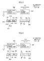
Fig. 3] Fig. 3 is a diagram illustrating a manufacturing method for absorbent articles according to a modified example 1 of the present invention. - [
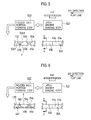
Fig. 4] Fig. 4 is a diagram illustrating a manufacturing method for absorbent articles according to a modified example 2 of the present invention. - [
Fig. 5] Fig. 5 is a diagram illustrating a manufacturing method for absorbent articles according to a modified example 3 of the present invention. - [
Fig. 6] Fig. 6 is a diagram illustrating a manufacturing method for absorbent articles according to a modified example 4 of the present invention. - [
Fig. 7] Fig. 7 is a diagram illustrating a manufacturing method for absorbent articles according to a modified example 5 of the present invention. - [
Fig. 8] Fig. 8 is a diagram illustrating a manufacturing method for absorbent articles according to a modified example 6 of the present invention. - [
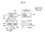
Fig. 9] Fig. 9 is a diagram illustrating a manufacturing method for absorbent articles according to a modified example 7 of the present invention. - [
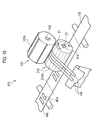
Fig. 10] Fig. 10 is a perspective view of a latch member placing structure 210 according to a second embodiment of the present invention. - [
Fig. 11] Fig. 11 is a perspective view of a folded back portion forming structure 320 according to the second embodiment of the present invention. - [
Fig. 12] Fig. 12 is a perspective view of abonding structure 330 according to the second embodiment of the present invention. - Description will be given of a manufacturing method for absorbent articles according to a first embodiment of the present invention with reference to
Figs. 1 and2 . - According to the manufacturing method for absorbent articles according to the first embodiment, absorbent articles, each of which including a
front waistline member 20b, arear waistline member 20a, and a crotch member (absorber body) 10 connecting thefront waistline member 20b and therear waistline member 20a, can be manufactured. For example, open-type diapers can be manufactured. - Hereinafter, with reference to
Fig. 1 , description will be given of a manufacturing method for absorbent articles according to this embodiment. - It is assumed that, as shown in
Fig. 1 , the manufacturing method for the absorbent articles according to this embodiment uses: a flap line on which a long continuum of flaps (flap continuum 130) is transported; an absorber line on which a long continuum of crotch members (crotch member continuum 110) is transported; and a main body line on which a pair of acontinuum 120b of front waistline members and acontinuum 120a of rear waistline members (a pair of a frontwaistline member continuum 120b and a rearwaistline member continuum 120a) is transported. - Note that, in this embodiment, an example is described in which an MD direction (moving direction) of the flap line and the MD directions respectively of the main body line and the absorber line are the same, as shown in
Fig. 4 . However, the present invention is not limited to this example. - Firstly, steps performed on the absorber line, on which the absorbers placed on the
crotch members 10 are transported, will be described. - In step S11, a crusher crushes pulp sheets to produce crushed pulps. Thereafter, when the crushed pulps pass through a pulp supply duct, a super absorbent polymer (SAP) is mixed thereto.
- Then, the mixture of the crushed pulp and the super absorbent polymer, which is supplied from the pulp supply duct, is layered in a predetermined shape by use of a layer drum, thereby absorber cores 1 (absorbers) are formed.
- In step S12, on
sheet tissues 2a being continuously transported in the MD direction of the absorber line, theabsorber cores 1 are placed by a predetermined interval length in the MD direction of the absorber line. - Subsequently, on the
sheet tissues 2a,sheet tissues 2b being continuously transported in the MD direction of the absorber line is layered. Here, on the sheet tissues2a, a plurality ofabsorber cores 1 is placed along the MD line of the absorber line. - In step S13, top sheets (liquid permeable) 12b being continuously transported in the MD direction of the absorber line are respectively placed on and bonded with the
sheet tissues 2b. In addition, back sheets (liquid impermeable) 12a being continuously transported in the MD direction of the absorber line are respectively placed under and bonded with thesheet tissues 2a. - In step S14, leak barriers 3 formed of different members are bonded onto both side edges of the
crotch members 10 in the MD direction of the absorber line. - In step S15, the crotch member members (absorber bodies10) being continuously transported in the MD direction of the absorber line are transported by use of a rotation of a rotating drum. Concurrently, the crotch member continuum 110 is cut in the CD direction by a predetermined interval length, by use of a cutter roll arranged opposite to the outer peripheral surface of the rotating drum. Thereby the
crotch members 10 are formed. - Secondly, steps performed on the flap line, on which the
flaps 30 to be placed on therear waistline members 20a are transported, will be described. - In step S21, in a part of
regions 30A each constituting one flap on theflap continuum 130 having a long shape and being continuously transported on the flap line,latch members - Specifically, on the
flap continuum 130, thelatch members flap continuum 130, by a predetermined interval length. Here, a length of each of thelatch members flap continuum 130 in a CD direction of the flap line. - In this regard, when hook members (male members) are placed as the
latch members front waistline members 20b. - Note that, in the present embodiment, the
front waistline members 20b are made of a non-woven fabric. Accordingly, the predetermined regions of thefront waistline members 20b themselves can serve as the hooked members even when the hooked members are not additionally provided. - In step S22, in the regions including the
latch members aforementioned regions 30A, pairs of foldedback portions - As shown in
Fig. 2A , each of the foldedback portions 50a includes: a first cut portion (first slit) 50a3 formed to extend in the CD direction of the flap line (that is, the direction crossing the moving direction), and two second cut portions (second slits) 50a1 and 50a2 formed to extend in the MD direction of the flap line. - Meanwhile, each of the folded
back portions 50b includes: a first cut portion (first slit) 50b3 formed to extend in the CD direction of the flap line, and two second cut portions (second slits) 50b1 and 50b2 formed to extend in the MD direction of the flap line. - Here, consider the case where each of the folded
back portions 50b is folded back outwardly in the MD direction of the flap line, and the foldedback portion 50a is folded back outwardly in the opposite MD direction of the flap, line like hinges as shown inFig. 2B . Even in this case, theflap continuum 130 is not entirely folded back in the CD direction of the flap line until each of the absorbent article is cut. Accordingly, it is possible to prevent theflap continuum 130 from being turned over while being transported. - In this regard, at least a part of the first cut portion (first slit) 50a3 and 50b3, and the second cut portions (second slits) 50a1, 50a2, 50b1, and 50b2 may be formed by a potential cut line, such as a perforated line.
- In particular, it is preferable that a part of the first cut portions (first slit) 50a3 and 50b3 be formed by the potential cut line such as the perforated line. This configuration makes it possible to prevent the
flap continuum 130 from being turned over while theflap continuum 130 is transported on the flap line. - Further, a part of the first cut portion (first slit) 50a3 and 50b3, and the second cut portions (second slits) 50a1, 50a2, 50b1, and 50b2 may be straight or curved.
- Furthermore, steps S21 and S22 described above may be performed in reverse order. To be more specific, in step S22, the
latch members portions portions regions 30A each constituting oneflap 30 on theflap continuum 130 having a long shape and being continuously transported on the flap line. - Thirdly, steps performed on the main body line, on which the front
waistline member continuum 120b and the rearwaistline member continuum 120a are transported, will be described. - In step S31, a pair of continuums of waistline members (the front
waistline member continuum 120b and the rearwaistline member continuum 120a) both having a long shape is produced from non-woven fabric and is transported in the MD direction of the main body line. - Note that, the front
waistline member continuum 120b and the rearwaistline member continuum 120a may have stretching properties. - In step S32, the
crotch members 10 each formed in step S15 on the absorber line is placed while being spaced apart from one another in the MD direction of the main body line, between the front waistline member continuum120b and the rearwaistline member continuum 120a. Here, both of the front waistline member continuum120b and the rearwaistline member continuum 120a have a long shape and are continuously transported on the main body line. - In step S33, on the main body line, the
flap continuum 130 is bonded to the rearwaistline member continuum 120a so that theregions 30A each constituting theflaps 30 on theflap continuum 130 respectively corresponds to theregions 20A each constituting the absorbent articles (rear waistline members 20a). - In other words, the
flap continuum 130 is bonded to the rearwaistline member continuum 120a so that thelatch members rear waistline members 20a of the absorbent articles. - Specifically, it is preferable that the
regions - In this regard, in step S33, it is preferable that the
flap continuum 130 be bonded on the rearwaistline member continuum 120a by use of a thermo compression or the like, using an embossing roller or ultrasonic waves. Further, the thermoplastic resin may be applied onto the entire back surface side of theflap continuum 130. Furthermore, the thermoplastic resin may be applied onto only a part of the back surface side of theflap continuum 130. - Moreover, in step S33, the
latch members portions waistline member continuum 120a. - In step S34, on the main body line, the front
waistline member continuum 120b and the rearwaistline member continuum 120a are cut in the CD direction of the main body line by a predetermined interval length. - Specifically, the front
waistline member continuum 120b and the rearwaistline member continuum 120b are cut so that each lengths L3 of thefront waistline members 20b in the width direction of the absorbent articles and each lengths L2 of therear waistline members 20a in the width direction of the absorbent articles can be equal. - Note that, in the above-described example, description has been given of the example in which the
flap continuum 130, on which thelatch members front waistline members 20b are placed, is placed on the rearwaistline member continuum 120a. However, the present invention is not limited to this example but can be applied to an example in which theflap continuum 130, on which thelatch members front waistline members 20b are placed, is placed on the frontwaistline member continuum 120b. - According to the manufacturing method for the absorbent articles according to the first embodiment of the present invention, the pairs of folded back
portions flap continuum 130 is not entirely folded back in the CD direction of the flap line until each of the absorbent article is cut. Accordingly, it is possible to form the absorbent articles that can be easily unfolded and developed by the user, and to prevent a problem that the absorbent articles are torn off on the flap line and thereby the flap continuum cannot be continuously transported on the flap line, or a problem that high level controls are required for continuously transporting the flap continuum on the flap line and thereby the manufacturing facility for the diapers becomes complex. - According to the manufacturing method for the absorbent articles of the first embodiment of the present invention, not the
flaps 30, theflap continuum 130 is placed on therear waistline continuum 120a. Accordingly, sophisticated manufacturing facility is not required. - According to the manufacturing method for the absorbent articles of the first embodiment of the present invention, the
front waistline continuum 120b and therear waistline continuum 120a are continuously transported and thereby each end portion of thefront waistline continuum 120b and therear waistline continuum 120a can be easily stacked, and the frontwaistline member continuum 120b and the rearwaistline member continuum 120a thus stacked can be simultaneously cut. Thus, open-type diapers and pants-type diapers can be manufactured by the same cutting step. Therefore, the open-type diaper and the pants-type diaper can be manufactured without changing the cutting step or a cutter itself. - With reference to
Fig. 3 , description will be given of a manufacturing method for absorbent articles according to a modified example 1 of the present invention. Hereinafter, the manufacturing method for the absorbent articles according to the modified example 1 of the present invention will be described, mainly focusing on the differences from the manufacturing method for the absorbent articles according to the first embodiment of the present invention. - As shown in
Fig. 3 , on the process performed on the flap line, in step S22,latch members regions 30A each constituting oneflap 30 on theflap continuum 130 having a long shape and being transported on the flap line. - In step S22, in each regions including the
latch members regions 30A, each pairs of folded backportions - As shown in
Fig. 3 , it is assumed that each pairs of folded backportions - Here, the first cut-out portion (first trimming) 510 is placed approximately in the vicinity of the center region in the CD direction of the flap line, as shown in
Fig. 3 . - In this case, it is preferable that at least a part of the second cut portions (second slits) 51a1, 51a2, 51b1 and 51b2 be formed by the potential cut line such as the perforated line. This configuration makes it possible to prevent the folded back
portions flap continuum 130 is transported on the flap line. - With reference to
Fig. 4 , description will be given of a manufacturing method for absorbent articles according to a modified example 2 of the present invention. Hereinafter, the manufacturing method for the absorbent articles according to the modified example 2 of the present invention will be described, mainly focusing on the differences from the manufacturing method for the absorbent articles according to the first embodiment of the present invention. - As shown in
Fig. 4 , on the process performed on the flap line, in step S22,latch members regions 30A each constituting oneflap 30 on theflap continuum 130 having a long shape and being transported on the flap line. - In step S22, in each regions including the
latch members regions 30A, each pairs of folded backportions - As shown in
Fig. 4 , it is assumed that each pairs of folded backportions - Here, as shown in
Fig. 4 , the first cut-out portion (first trimming) 520 is placed so as to extend in the CD direction from the center of the flap line to the edge X. - In this case, it is preferable that at least a part of the second cut portions (second slits) 51a1 and 52b1 be formed by the potential cut line such as the perforated line. This configuration makes it possible to prevent the folded back
portions flap continuum 130 is transported on the flap line. - With reference to
Fig. 5 , description will be given of a manufacturing method for absorbent articles according to a modified example 3 of the present invention. Hereinafter, the manufacturing method for the absorbent articles according to the modified example 3 of the present invention will be described, mainly focusing on the differences from the manufacturing method for the absorbent articles according to the first embodiment of the present invention. - As shown in
Fig. 5 , on the process performed on the flap line, in step S21, in the part ofregions 30A each constituting oneflap 30 on theflap continuum 130 having a long shape and being transported on the flap line,latch members - In step S22, in each regions including the
latch members regions 30A, each pairs of folded backportions - As shown in
Fig. 5 , it is assumed that each pairs of folded backportions - Here, as shown in
Fig. 5 , the first cut-out portion (first trimming) 530 is placed so as to extend in the CD direction from the center of the flap line to the edge Y (the edge opposite to the aforementioned edge X). - In this case, it is preferable that at least a part of the second cut portions (second slits) 53a1 and 53b1 be formed by the potential cut line such as the perforated line. This configuration makes it possible to prevent the folded back
portions flap continuum 130 is transported on the flap line. - With reference to
Fig. 6 , description will be given of a manufacturing method for absorbent articles according to a modified example 4 of the present invention. Hereinafter, the manufacturing method for absorbent articles according to the modified example 4 of the present invention will be described, mainly focusing on the differences from the manufacturing method for absorbent articles according to the first embodiment of the present invention. - As shown in
Fig. 6 , on the process performed on the flap line, in step S21, in the part ofregions 30A each constituting oneflap 30 on theflap continuum 130 having a long shape and being transported on the flap line,latch members - In step S22, in each regions including the
latch members regions 30A, each pairs of folded backportions - As shown in
Fig. 6 , it is assumed that each pairs of folded backportions - Here, as shown in
Fig.6 , the first cut-out portion (first trimming) 540 is placed so as to extend in the CD direction from the center of the flap line to the edge X. - With reference to
Fig. 7 , description will be given of a manufacturing method for absorbent articles according to a modified example 1 of the present invention. Hereinafter, the manufacturing method for absorbent articles according to the modified example 5 of the present invention will be described, mainly focusing on the differences from the manufacturing method for absorbent articles according to the first embodiment of the present invention. - As shown in
Fig. 7 , on the process performed on the flap line, in step S21, in the part ofregions 30A each constituting oneflap 30 on theflap continuum 130 having a long shape and being transported on the flap line,latch members - In step S22, in each regions including the
latch members regions 30A, each pairs of folded backportions - As shown in
Fig. 7 , it is assumed that each pairs of folded backportions - Here, as shown in
Fig.7 , the first cut-out portion (first trimming) 550 is placed so as to extend in the CD direction from the center of the flap line to the edge Y (the edge opposite to the aforementioned edge X). - With reference to
Fig. 8 , description will be given of a manufacturing method for absorbent articles according to a modified example 6 of the present invention. Hereinafter, the manufacturing method for an absorbent article according to the modified example 6 of the present invention will be described, mainly focusing on the differences from the manufacturing method for the absorbent articles according to the first embodiment of the present invention. - As shown in
Fig. 8 , on the process performed on the flap line, in step S21, in the part ofregions 30A each constituting oneflap 30 on theflap continuum 130 having a long shape and being transported on the flap line,latch members - In step S22, in each regions including the
latch members regions 30A, each pairs of folded backportions - As shown in
Fig. 8 , it is assumed that the pairs of folded backportions - Here, as shown in
Fig.8 , the first cut-out portion (first trimming) 560 is placed so as to extend in the CD direction from the second cut-outportion 561a to the second cut-outportion 561b. - With reference to
Fig. 9 , description will be given of a manufacturing method for absorbent articles according to a modified example 7 of the present invention. Hereinafter, the manufacturing method for absorbent articles according to the modified example 7 of the present invention will be described, mainly focusing on the differences from the manufacturing method for absorbent articles according to the first embodiment of the present invention. - As shown in
Fig. 9 , on the process performed on the flap line, in step S21, in thepart regions 30A each constituting oneflap 30 on theflap continuum 130 having a long shape and being transported on the flap line, fourlatch members - In step S22, in each regions including the
latch members regions 30A, pairs of folded back portions 57a and 57b that can be folded back to the MD direction of the flap line and a direction opposite to the MD direction are formed. - As shown in
Fig. 9 , it is assumed that the folded back portion 57a includes: a first cut portion (first slit) 57a3 formed to extend in the CD direction of the flap line, and two second cut portions (second slits) 57a1 and 57a2 each formed to extend in the MD direction of the flap line. - In addition, it is assumed that the folded back
portion 58a includes: a first cut portion (first slit) 58a3 formed to extend in the CD direction of the flap line, and two second cut portions (second slits) 58a1 and 58a2 each formed to extend in the MD direction of the flap line. - Further, it is assumed that the folded back portion 57b includes: a first cut portion (first slit) 57b3 formed to extend in the CD direction of the flap line, and two second cut portions (second slits) 57b1 and 57b2 each formed to extend in the MD direction of the flap line.
- Moreover, it is assumed that the folded back
portion 58b includes: a first cut portion (first slit) 58b3 formed to extend in the CD direction of the flap line, and two second cut portions (second slits) 58b1 and 58b2 each formed to extend in the MD direction of the flap line. - In this regard, in step S21, four latch members may be placed in a part of
regions 30A each constituting oneflap 30 on theflap continuum 130 having a long shape and being transported on the flap line. Further, in step S22, more than two folded back portions may be formed in the region including these latch members. - In this case, it is preferable that at least a part of the first cut portions (first slits) 57a3, 57b3, 58a3, and 58b3 be formed by the potential cut line such as the perforated line. This configuration makes it possible to prevent the folded back
portions flap continuum 130 is transported on the flap line. - Hereinbelow, a manufacturing apparatus for absorbent articles according to the second embodiment will be described by referring to
Figs. 10 to 12 . The manufacturing apparatus for the absorbent articles according to the second embodiment is provided with: a latchmember placing structure 310; a folded back portion forming structure 320; and abonding structure 330. - First, the latch
member placing structure 310 according to the second embodiment will be described by referring to the accompanying drawings.Fig. 10 is a perspective view of the latchmember placing structure 310 according to the second embodiment of the present invention. - As shown in
Fig. 10 , the latchmember placing structure 310 places thelatch members flap continuum 130 having a long shape and being continuously transported on the flap line (above-described step S21). - The latch
member placing structure 310 includes: anupper blade roll 313 configured to rotate by using ashaft 312 as a center; and alower blade roll 315 configured to rotate by using ashaft 314 as a center. - The
upper blade roll 313 is provided with a plurality ofblades 313A placed by a predetermined interval length on the outer peripheral surface thereof. Here, the plurality ofblades 313A is placed along theshaft center 312. Thelower blade roll 315 is provided with: asuction hole 315A configured to suck theflaps 30 formed by cutting theflap continuum 130; and a stationary blade (not shown) configured to cut theflap continuum 130 with theblade 313A. - On the peripheral surface of the
lower blade roll 315 includes a first zone Z1 that sucks and holds theflap continuum 130 with a predetermined suction force, and a second zone Z2 that sucks and holds theflaps 30 formed by cutting theflap continuum 130, with a suction force stronger than that of the first zone Z1. - When the
latch member continuum 140 passes through the first zone Z1, while slipping around the peripheral surface of thelower blade roll 315, thelatch member continuum 140 is sucked by thesuction holes 315A formed on the first zone Z1 so as to be held by the peripheral surface of thelower blade roll 315. At this time, thelatch member continuum 140 is cut between theblade 313A and the stationary blade. Thereby, thelatch members - When the
latch members lower blade roll 315, theflaps 30 are sucked by thesuction holes 315A formed on the second zone Z2 so as to be held by the peripheral surface of thelower blade roll 315. Then, thelatch members waistline member continuum 120a by the rotation of thelower blade roll 315 so as to be attached thereon. - Next, the folded back portion forming structure 320 according to the second embodiment of the present invention will be described by referring to the accompanying drawings.
Fig. 11 is a perspective view of the folded back portion forming structure 320 according to the second embodiment of the present invention. - As shown in
Fig. 11 , the folded back portion forming structure 320 forms pairs of folded backportions - The folded back portion forming structure 320 is provided with: a cutting
roll 321 configured to rotate by using a shaft (not shown) as a center; and a nippingroll 322 configured to nip theflap continuum 130 between the cutting roll 231 and the nipping roll 232. - The circumferential velocity (V7) of the cutting
roll 321 is substantially same as the moving velocity (V4) of theflap continuum 130. The cutting roll 231 includes a folding backprocess blade 321A for forming thefolding portions process blade 321A is formed in corresponding to the shape of thefolding portions - Subsequently, the
bonding structure 330 according to the second embodiment of the present invention will be described by referring to the accompanying drawings.Fig. 12 is a perspective view of thebonding structure 330 according to the second embodiment of the present invention. - As shown in
Fig. 12 , the bodingstructure 330 bonds the rearwaistline member continuum 120a and theflaps 30, so that each of the area constituting each flaps 30 corresponds to each area constituting each of the absorbent article on the rearwaistline member continuum 120a. - The
bonding structure 330 bonds theflap continuum 130 and the rearwaistline member continuum 120a on the main body line (above-described step S33), so that the MD direction of the flap line corresponds to the MD direction of the main body line. Thebonding structure 330 is provided with a pair ofrollers rollers flap continuum 130. - The
roller 331 guides theflap continuum 130 to the rearwaistline member continuum 120a. Meanwhile, theroller 332 nips the rearwaistline member continuum 120a and theflap continuum 130, and faces theroller 331. The pair ofrollers waistline member continuum 120a and theflap continuum 130 therebetween, thereby thebonding structure 330 bonds the rearwaistline member continuum 120a and theflaps 30. - It is a matter of course that orders of performing the steps in the above-described manufacturing method for the absorbent articles is not limited to those described above as long as the absorbent article can be manufactured, and the steps to be performed can be appropriately selected in accordance with the intended purpose.
- As described above, the present invention has been described in detail by using the above-described embodiments. However, it is obvious for a person skilled in the art that the present invention is not limited to the embodiments described in this specification. The present invention can be implemented as a modification and an amended embodiment without departing from the content and scope of the present invention which is defined by the description of the scope of claims. Accordingly, the description of the present invention is intended to give description as an example and does not have any meaning to limit the present invention.
- This application is based upon and claims the benefit of priority from the prior Japanese Patent Application No.
JP 2008-094065, filed on March 31, 2008 JP 2009-074778, filed on March 25, 2009 - As described above, according to absorbent articles of the present invention, there can be provided a manufacturing method for absorbent articles being able to form side flaps that can be easily unfolded and developed by the user of the manufactured diaper, and being able to achieve a continuous transportation of a flap continuum on a flap line without using high level controls.
Claims (8)
- A manufacturing method for absorbent articles each including front waistline members, rear waistline members, and crotch members, the crotch members connecting each of the front waistline members and the rear waistline members, comprising:placing pairs of folded back portions that can be folded toward a moving direction of a flap line and a direction opposite to the moving direction, in a part of regions each constituting flaps from a flap continuum having a long shape and being continuously transported on the flap line;
placing latch members that can be attached to and locked in predetermined regions, on each of the pairs of folded back portions; and
bonding a front waistline member continuum or a rear waistline member continuum onto the flap continuum, so that regions each constituting the flaps corresponds to regions each constituting the absorbent articles on the front waistline member continuum or on the rear waistline member continuum. - The manufacturing method for the absorbent articles according to claim 1, wherein, in placing the pairs of folded back portions, each of the pairs of folded back portions include: at least any one of a first cut portion and a first cut-out portion both formed to extend in a direction crossing the moving direction of the flap line; and at least any one of a second cut portion and a second cut-out portion both formed to extend in the moving direction of the flap line.
- The manufacturing method for the absorbent articles according to claim 1, wherein,
in the bonding, the latch members placed on the pairs of folded back portions are attached to and locked on the front waistline member continuum or the rear waistline member continuum. - The manufacturing method for the absorbent articles according to claim 1, further comprising:placing the crotch members so that each of the crotch members is apart from each other in a moving direction of a main body line, between the front waistline member continuum and the rear waistline member continuum both having a long shape and being transported continuously on the main body line.
- The manufacturing method for the absorbent articles according to claim 1, wherein,
in the bonding, the front waistline member continuum or the rear waistline member continuum is bonded onto the flap continuum. - The manufacturing method for the absorbent articles according to claim 1, wherein,
in the bonding, the flap continuum is placed so that each of the flaps covers edge portions of the absorbent articles placed under the crotch members. - The manufacturing method for the absorbent articles according to claim 1, further comprising:cutting the front waistline member continuum and the rear waistline member continuum so that each lengths of the front waistline members in a width direction of the absorbent articles is equal to each length of the rear waistline members in a width direction of the absorbent articles.
- A manufacturing apparatus for absorbent articles each including front waistline members, rear waistline members, and crotch members, the crotch members connecting each of the front waistline members and each of the rear waistline members, comprising:a latch member placing structure configured to place latch members that can be attached to and locked in predetermined regions, on a flap continuum having a long shape and being continuously transported on a flap line;
a folded back portion forming structure configured to form pairs of folded back portions that can be folded toward a moving direction of the flap line and a direction opposite to the moving direction, in a part of regions each constituting flaps from the flap continuum; and
a bonding structure configured to bond a front waistline member continuum or a rear waistline member continuum onto the flap continuum, so that regions each constituting the flaps respectively corresponds to regions each constituting the absorbent articles on the front waistline member continuum or on the rear waistline member continuum.
Applications Claiming Priority (3)
| Application Number | Priority Date | Filing Date | Title |
|---|---|---|---|
| JP2008094065 | 2008-03-31 | ||
| JP2009074778A JP5328438B2 (en) | 2008-03-31 | 2009-03-25 | Absorbent article manufacturing method and absorbent article manufacturing apparatus |
| PCT/JP2009/056623 WO2009123179A1 (en) | 2008-03-31 | 2009-03-31 | Manufacturing method for absorbent products and manufacturing device for absorbent products |
Publications (2)
| Publication Number | Publication Date |
|---|---|
| EP2266512A1 true EP2266512A1 (en) | 2010-12-29 |
| EP2266512A4 EP2266512A4 (en) | 2013-10-09 |
Family
ID=41135551
Family Applications (1)
| Application Number | Title | Priority Date | Filing Date |
|---|---|---|---|
| EP09726518.5A Withdrawn EP2266512A4 (en) | 2008-03-31 | 2009-03-31 | Manufacturing method for absorbent products and manufacturing device for absorbent products |
Country Status (8)
| Country | Link |
|---|---|
| US (1) | US20110139336A1 (en) |
| EP (1) | EP2266512A4 (en) |
| JP (1) | JP5328438B2 (en) |
| CN (1) | CN101983045B (en) |
| AU (1) | AU2009232765A1 (en) |
| CA (1) | CA2720340A1 (en) |
| TW (1) | TW201002279A (en) |
| WO (1) | WO2009123179A1 (en) |
Cited By (2)
| Publication number | Priority date | Publication date | Assignee | Title |
|---|---|---|---|---|
| EP2266516A4 (en) * | 2008-03-31 | 2012-12-19 | Unicharm Corp | Absorbent products |
| WO2013092233A1 (en) * | 2011-12-22 | 2013-06-27 | Sca Hygiene Products Ab | Disposable absorbent product with fastening components and related methods |
Families Citing this family (7)
| Publication number | Priority date | Publication date | Assignee | Title |
|---|---|---|---|---|
| JP2911296B2 (en) | 1991-04-19 | 1999-06-23 | 吉富製薬株式会社 | Method for producing tris (4-hydroxybenzyl) isocyanurate compound |
| CN104394817B (en) * | 2012-06-29 | 2016-09-28 | 宝洁公司 | Method for attaching elastic components to absorbent articles |
| WO2014208363A1 (en) * | 2013-06-25 | 2014-12-31 | 株式会社瑞光 | Absorbent article and method for manufacturing same |
| JP6383723B2 (en) * | 2013-06-25 | 2018-08-29 | 株式会社瑞光 | Absorbent article with wing and manufacturing method thereof |
| JP6305373B2 (en) * | 2015-06-30 | 2018-04-04 | ユニ・チャーム株式会社 | Method for continuously producing absorbent articles |
| WO2017161213A1 (en) | 2016-03-18 | 2017-09-21 | The Procter & Gamble Company | Method and apparatus for advancing and folding an absorbent article |
| EP3429533B1 (en) | 2016-03-18 | 2022-04-06 | The Procter & Gamble Company | Apparatus for advancing and folding an absorbent article |
Family Cites Families (16)
| Publication number | Priority date | Publication date | Assignee | Title |
|---|---|---|---|---|
| JPS4849542A (en) * | 1971-05-12 | 1973-07-12 | ||
| JPS59165404U (en) * | 1983-04-21 | 1984-11-06 | 株式会社瑞光 | paper diaper |
| US5540796A (en) * | 1994-08-03 | 1996-07-30 | Kimberly-Clark Corporation | Process for assembling elasticized ear portions |
| JP3575990B2 (en) * | 1998-06-30 | 2004-10-13 | ユニ・チャーム株式会社 | Disposable diapers |
| US6730070B2 (en) * | 2000-09-29 | 2004-05-04 | Sca Hygiene Products Ab | Absorbent product having a fastening arrangement |
| SE521378C2 (en) * | 2000-09-29 | 2003-10-28 | Sca Hygiene Prod Ab | Absorbent articles with fastening device |
| US20030055389A1 (en) * | 2001-09-14 | 2003-03-20 | Sanders Donald J. | Method and apparatus for assembling refastenable absorbent garment |
| EP1300123A1 (en) * | 2001-10-02 | 2003-04-09 | 3M Innovative Properties Company | Method of applying a fastener portion to a diaper |
| US7214285B2 (en) * | 2001-10-02 | 2007-05-08 | 3M Innovative Properties Company | Method of applying a fastener portion to a diaper |
| US7201744B2 (en) * | 2001-12-28 | 2007-04-10 | Kimberly-Clark Worldwide, Inc. | Refastenable absorbent garment and method for assembly thereof |
| EP1452158A1 (en) * | 2003-02-28 | 2004-09-01 | 3M Innovative Properties Company | Method of preparing closure components suitable for use in diapers |
| JP4015081B2 (en) * | 2003-07-31 | 2007-11-28 | ユニ・チャーム株式会社 | Method for folding a continuously supplied web in two and apparatus therefor |
| CN100464727C (en) * | 2003-12-24 | 2009-03-04 | 株式会社瑞光 | Wearing article and method for manufacturing same |
| JP4537263B2 (en) * | 2005-06-08 | 2010-09-01 | 白十字株式会社 | Disposable absorbent article and method for producing the same |
| JP2008094065A (en) | 2006-10-16 | 2008-04-24 | Union Seiki:Kk | Metallic article with knurled cylindrical surface and device for engraving figure/letter on cylindrical surface |
| JP5061812B2 (en) | 2007-09-25 | 2012-10-31 | 三菱電機株式会社 | Air conditioner indoor unit |
-
2009
- 2009-03-25 JP JP2009074778A patent/JP5328438B2/en not_active Expired - Fee Related
- 2009-03-31 CA CA2720340A patent/CA2720340A1/en not_active Abandoned
- 2009-03-31 AU AU2009232765A patent/AU2009232765A1/en not_active Abandoned
- 2009-03-31 TW TW098110754A patent/TW201002279A/en unknown
- 2009-03-31 EP EP09726518.5A patent/EP2266512A4/en not_active Withdrawn
- 2009-03-31 US US12/935,594 patent/US20110139336A1/en not_active Abandoned
- 2009-03-31 CN CN2009801119034A patent/CN101983045B/en not_active Expired - Fee Related
- 2009-03-31 WO PCT/JP2009/056623 patent/WO2009123179A1/en not_active Ceased
Cited By (7)
| Publication number | Priority date | Publication date | Assignee | Title |
|---|---|---|---|---|
| EP2266516A4 (en) * | 2008-03-31 | 2012-12-19 | Unicharm Corp | Absorbent products |
| US8814844B2 (en) | 2008-03-31 | 2014-08-26 | Unicharm Corporation | Absorbent article |
| WO2013092233A1 (en) * | 2011-12-22 | 2013-06-27 | Sca Hygiene Products Ab | Disposable absorbent product with fastening components and related methods |
| CN103997996A (en) * | 2011-12-22 | 2014-08-20 | Sca卫生用品公司 | Disposable absorbent product with fastening components and related methods |
| US9017306B2 (en) | 2011-12-22 | 2015-04-28 | Sca Hygiene Products Ab | Disposable absorbent product with fastening components and related methods |
| RU2571252C1 (en) * | 2011-12-22 | 2015-12-20 | Ска Хайджин Продактс Аб | Disposable absorbent product with fastening components and related methods |
| CN103997996B (en) * | 2011-12-22 | 2016-11-16 | Sca卫生用品公司 | There is disposable absorbent products and the correlation technique of secure component |
Also Published As
| Publication number | Publication date |
|---|---|
| US20110139336A1 (en) | 2011-06-16 |
| JP2009261919A (en) | 2009-11-12 |
| EP2266512A4 (en) | 2013-10-09 |
| CA2720340A1 (en) | 2009-10-08 |
| TW201002279A (en) | 2010-01-16 |
| WO2009123179A1 (en) | 2009-10-08 |
| AU2009232765A1 (en) | 2009-10-08 |
| CN101983045A (en) | 2011-03-02 |
| CN101983045B (en) | 2013-06-05 |
| JP5328438B2 (en) | 2013-10-30 |
Similar Documents
| Publication | Publication Date | Title |
|---|---|---|
| EP2275064A1 (en) | Manufacturing method for absorbent products and manufacturing device for absorbent products | |
| CA2720340A1 (en) | Manufacturing method for absorbent products and manufacturing device for absorbent products | |
| US8596324B2 (en) | Web conveying apparatus and web conveying method | |
| TW201103505A (en) | Device for producing absorbent article and method for producing absorbent article | |
| US8980040B2 (en) | Manufacturing method of absorbent article | |
| RU2524598C2 (en) | Conveyor for canvas and method for absorbing product manufacturing | |
| EP2275063B1 (en) | Method of manufacturing absorptive article and device for manufacturing absorptive article | |
| US8590134B2 (en) | Manufacturing method for absorbent products and manufacturing device for absorbent products | |
| US20100219224A1 (en) | Conveyor and method of manufacturing absorbent article | |
| JP6711849B2 (en) | Absorbent article manufacturing method | |
| EP2263626B1 (en) | Manufacturing method for absorbent products and manufacturing device for absorbent products | |
| WO2009123212A1 (en) | Method of manufacturing absorptive article and device for manufacturing absorptive article |
Legal Events
| Date | Code | Title | Description |
|---|---|---|---|
| PUAI | Public reference made under article 153(3) epc to a published international application that has entered the european phase |
Free format text: ORIGINAL CODE: 0009012 |
|
| 17P | Request for examination filed |
Effective date: 20101027 |
|
| AK | Designated contracting states |
Kind code of ref document: A1 Designated state(s): AT BE BG CH CY CZ DE DK EE ES FI FR GB GR HR HU IE IS IT LI LT LU LV MC MK MT NL NO PL PT RO SE SI SK TR |
|
| AX | Request for extension of the european patent |
Extension state: AL BA RS |
|
| RIN1 | Information on inventor provided before grant (corrected) |
Inventor name: SAKAGUCHI, SATORU |
|
| DAX | Request for extension of the european patent (deleted) | ||
| A4 | Supplementary search report drawn up and despatched |
Effective date: 20130906 |
|
| RIC1 | Information provided on ipc code assigned before grant |
Ipc: A61F 13/56 20060101ALI20130902BHEP Ipc: A61F 13/15 20060101AFI20130902BHEP Ipc: A61F 13/49 20060101ALI20130902BHEP |
|
| 17Q | First examination report despatched |
Effective date: 20150825 |
|
| STAA | Information on the status of an ep patent application or granted ep patent |
Free format text: STATUS: THE APPLICATION IS DEEMED TO BE WITHDRAWN |
|
| 18D | Application deemed to be withdrawn |
Effective date: 20160105 |