EP2265422B1 - Razor handle for a retractable shaving cartridge and a razor comprising such a razor handle - Google Patents
Razor handle for a retractable shaving cartridge and a razor comprising such a razor handle Download PDFInfo
- Publication number
- EP2265422B1 EP2265422B1 EP08736148.1A EP08736148A EP2265422B1 EP 2265422 B1 EP2265422 B1 EP 2265422B1 EP 08736148 A EP08736148 A EP 08736148A EP 2265422 B1 EP2265422 B1 EP 2265422B1
- Authority
- EP
- European Patent Office
- Prior art keywords
- shaving
- release
- shaving cartridge
- carrier
- button
- Prior art date
- Legal status (The legal status is an assumption and is not a legal conclusion. Google has not performed a legal analysis and makes no representation as to the accuracy of the status listed.)
- Not-in-force
Links
- 230000000717 retained effect Effects 0.000 claims description 3
- 210000003811 finger Anatomy 0.000 description 8
- 239000013536 elastomeric material Substances 0.000 description 2
- 238000004026 adhesive bonding Methods 0.000 description 1
- 230000014759 maintenance of location Effects 0.000 description 1
- 239000000463 material Substances 0.000 description 1
- 239000004033 plastic Substances 0.000 description 1
- 229920001169 thermoplastic Polymers 0.000 description 1
- 239000004416 thermosoftening plastic Substances 0.000 description 1
- 210000003813 thumb Anatomy 0.000 description 1
Images






Classifications
-
- B—PERFORMING OPERATIONS; TRANSPORTING
- B26—HAND CUTTING TOOLS; CUTTING; SEVERING
- B26B—HAND-HELD CUTTING TOOLS NOT OTHERWISE PROVIDED FOR
- B26B21/00—Razors of the open or knife type; Safety razors or other shaving implements of the planing type; Hair-trimming devices involving a razor-blade; Equipment therefor
- B26B21/40—Details or accessories
- B26B21/4062—Actuating members, e.g. switches or control knobs; Adjustments
-
- B—PERFORMING OPERATIONS; TRANSPORTING
- B26—HAND CUTTING TOOLS; CUTTING; SEVERING
- B26B—HAND-HELD CUTTING TOOLS NOT OTHERWISE PROVIDED FOR
- B26B21/00—Razors of the open or knife type; Safety razors or other shaving implements of the planing type; Hair-trimming devices involving a razor-blade; Equipment therefor
- B26B21/08—Razors of the open or knife type; Safety razors or other shaving implements of the planing type; Hair-trimming devices involving a razor-blade; Equipment therefor involving changeable blades
- B26B21/14—Safety razors with one or more blades arranged transversely to the handle
- B26B21/22—Safety razors with one or more blades arranged transversely to the handle involving several blades to be used simultaneously
- B26B21/222—Safety razors with one or more blades arranged transversely to the handle involving several blades to be used simultaneously with the blades moulded into, or attached to, a changeable unit
- B26B21/225—Safety razors with one or more blades arranged transversely to the handle involving several blades to be used simultaneously with the blades moulded into, or attached to, a changeable unit the changeable unit being resiliently mounted on the handle
-
- B—PERFORMING OPERATIONS; TRANSPORTING
- B26—HAND CUTTING TOOLS; CUTTING; SEVERING
- B26B—HAND-HELD CUTTING TOOLS NOT OTHERWISE PROVIDED FOR
- B26B21/00—Razors of the open or knife type; Safety razors or other shaving implements of the planing type; Hair-trimming devices involving a razor-blade; Equipment therefor
- B26B21/40—Details or accessories
- B26B21/4012—Housing details, e.g. for cartridges
-
- B—PERFORMING OPERATIONS; TRANSPORTING
- B26—HAND CUTTING TOOLS; CUTTING; SEVERING
- B26B—HAND-HELD CUTTING TOOLS NOT OTHERWISE PROVIDED FOR
- B26B21/00—Razors of the open or knife type; Safety razors or other shaving implements of the planing type; Hair-trimming devices involving a razor-blade; Equipment therefor
- B26B21/40—Details or accessories
- B26B21/52—Handles, e.g. tiltable, flexible
- B26B21/521—Connection details, e.g. connection to razor heads
-
- B—PERFORMING OPERATIONS; TRANSPORTING
- B26—HAND CUTTING TOOLS; CUTTING; SEVERING
- B26B—HAND-HELD CUTTING TOOLS NOT OTHERWISE PROVIDED FOR
- B26B21/00—Razors of the open or knife type; Safety razors or other shaving implements of the planing type; Hair-trimming devices involving a razor-blade; Equipment therefor
- B26B21/40—Details or accessories
- B26B21/52—Handles, e.g. tiltable, flexible
- B26B21/522—Ergonomic details, e.g. shape, ribs or rubber parts
-
- B—PERFORMING OPERATIONS; TRANSPORTING
- B26—HAND CUTTING TOOLS; CUTTING; SEVERING
- B26B—HAND-HELD CUTTING TOOLS NOT OTHERWISE PROVIDED FOR
- B26B21/00—Razors of the open or knife type; Safety razors or other shaving implements of the planing type; Hair-trimming devices involving a razor-blade; Equipment therefor
- B26B21/40—Details or accessories
- B26B21/52—Handles, e.g. tiltable, flexible
- B26B21/528—Manufacture of razor handles
Definitions
- the invention is concerned with razor handles for a retractable shaving cartridge and razors comprising such a razor handle.
- the invention relates to a razor handle for a retractable shaving cartridge comprising:
- Such a razor handle allows a shaving cartridge connected to the shaving cartridge carrier to be located inside the housing when the razor in not used, hence protecting the shaving cartridge from any aggressive environment.
- a control mechanism for controlling the actuating member only when the shaving cartridge carrier is in said shaving position such as disclosed in WO2005/090017 .
- This patent application discloses a razor having two slidable shaving cartridges and a control mechanism for each shaving cartridge.
- Each control mechanism comprises flexible release buttons provided on the body which can activate the release mechanism only when the shaving cartridge carrier is in said shaving position.
- An object of the present invention is to provide a razor handle in which the release buttons provided on the body can activate the release mechanism only when the shaving cartridge carrier is in said shaving position.
- control member is movably mounted on the release button and the elongate body further includes at least a guide adapted for guiding the control member so that said control member be in the retracted position when the release-button is in the rest position and in the active position when the release-button is in the release position.
- control member is guided when moved between its retracted and active positions.
- the invention also concerns a razor comprising such a razor handle and a shaving cartridge connected to the shaving cartridge carrier.
- the shaving cartridge is preferably connected to shaving cartridge carrier such that the shaving cartridge extends out of the razor handle when the shaving cartridge carrier is in the shaving position and the shaving cartridge is located inside the housing when the shaving cartridge carrier is in the non-shaving position, and the release mechanism is preferably adapted to release the shaving cartridge only when the shaving cartridge carrier is in said shaving position.
- the shaving cartridge can further be provided with rearwardly protruding ribs connected to the razor handle and partly covered by the two lateral flanges of the razor handle when the shaving cartridge is connected to the shaving cartridge carrier.
- FIG 1 illustrates a razor 10 according to the present invention, having a razor handle 12 and a shaving cartridge 14 provided with one or several shaving blades 16.
- the razor handle 12 has an elongate body 18 extending in a longitudinal direction L between a front end 18A and a back end 18B.
- the body 18 has an upper face 18C opposite to a lower face 18D.
- the shaving cartridge 14 is preferably a disposable cartridge which can be connected to a shaving cartridge carrier 20 as illustrated on Figure 1B .
- This shaving cartridge carrier 20 is movable between a shaving position (depicted on Figure 1A or 1B ) in which the razor cartridge carrier 20 and the shaving cartridge 14 extend at least partly out of a housing 22 provided on the body 18, and a non-shaving position (depicted on Figure 1C ) in which the razor cartridge carrier 20 and the shaving cartridge 14 are retracted inside the housing 22.
- the housing 22 is hollow and preferably formed by an upper shell 22A and a lower shell 22B as illustrated on Figure 2 which are maintained together in a well-known way like for example by snap-fitting or gluing.
- An opening 24 at the front end 18A of the body 18 allows access to the inside of this hollow housing 22.
- the shaving cartridge carrier 20 is movable through this opening 24.
- the handle 12 is further provided with a release mechanism 26 provided on the shaving cartridge carrier 20.
- the release mechanism 26 includes an actuating member 28 which is adapted to actuate said release mechanism 26 so as to release the shaving cartridge 14 (not illustrated) carried on said shaving cartridge carrier 20.
- the release mechanism 26 comprises two arms 30 and 30 for connecting a shaving cartridge 14 to the shaving cartridge carrier 20.
- the arms 30 are elastically biased opposite to one another toward a cartridge locking position (see Figure 4B ) and movable toward one another into a cartridge release position (see Figure 4A ).
- Each arm 30 has a first end 30A including preferably a shell bearings 32 having a cylindrical concave front face 32A and a lateral edge 32B which protrudes outwardly and which has also a cylindrical shape.
- the front face 32A and the lateral edge 32B have the same cylindrical axis, corresponding to the axis of rotation A1 of the shaving cartridge 14.
- the two arms 30 and 30 may be disposed in a V shape, converging from a medial axis X from their first end 30A toward a second end 30B.
- the medial axis X is substantially parallel to the curved longitudinal axis C of the handle 12.
- the second ends 30B of the two arms 30 may be connected together by a hinge 34, formed for instance as a thin bridge of plastic material connecting the two arms 30 to each other when said arms are molded as a single piece.
- the hinge 34 may have a negligible resilient action, or no resilient action, on the two arms 30.
- the rear face 14A of the shaving cartridge 14 may include two inwardly facing arcuate slots 36 shaped in correspondence with the lateral edges 32B of the shell bearings 32 and adapted to receive said lateral edges 32B for pivotally mounting the shaving cartridge 14 onto the handle 12.
- These arcuate slots 36 may be formed respectively in two protruding ribs 38 and may be limited toward the handle 12, by a first arcuate concave surface 40 facing toward the shaving cartridge 14, and away from the handle 12, by a larger second arcuate convex surface 42 facing toward the handle 12.
- these rearwardly protruding ribs 38 are partly covered by two lateral flanges 21 provided on the razor handle 12. More specifically the lateral flanges 21 can be provided on the shaving cartridge carrier 20 and extend forward at the front end 18A of the handle body 18 in the direction of the shaving cartridge 14, at least as far as the two arms 30, the arms 30 being situated between said two lateral flanges 21.
- the rearwardly protruding ribs 38 and the lateral flanges 21 are preferably shaped in correspondence to partly cover said protruding ribs 38.
- the front faces 32A of the shell bearings 32 bear respectively on the second arcuate convex surfaces 42.
- Said second arcuate convex surfaces 42 may include respectively two notches 44 for receiving corresponding protrusions 46 of the shell bearings 32, so as to limit the angular range of rotation of the shaving cartridge 14.
- the rear face 14A of the shaving cartridge 14 may further include a central rib 48 having an edge forming a top cam surface 50 facing away from the shaving cartridge 14 toward the handle 12.
- the cam surface 50 may have a generally V shape and may include two substantially flat surfaces 52 which are slightly inclined relative to one another and which may be for instance separated from one another by a notch 54 hollowed out in the rib 48 in order to adapt the shaving cartridge 14 on a other type of handle having a flexible tongue which is inserted into said notch 54.
- the release mechanism 26 further includes a plunger 56 which is movably mounted, substantially along the medial axis X between the two arms 30.
- This plunger 56 has a central body 58 and two lateral wings 60 extending opposite to one another toward the two arms 30.
- the central body 58 extends longitudinally parallel to the medial axis X, between a first, substantially flat free end 58A which bears against the cam surface 50 of the shaving cartridge 14 (see Figure 4A ), and a second end 58B facing away from the shaving cartridge 14.
- a recess 62 may be hollowed out in the central body 58, said recess 62 forming a blind hole which opens at the second end 58B of the central body 58, in the direction of the handle 12.
- Each lateral wing 60 may include a detent 64 protruding parallel to the medial axis X toward the shaving cartridge 14, said detent 64 facing an inwardly extending protrusion 66 belonging to the corresponding arm 30.
- the protrusion 66 has an opening 68 which is limited inwardly by a rim 70 belonging to said protrusion 66.
- the lateral wings 60 of the plunger 56 may each have respectively two ribs 72 which extend in a medial plane of the arms 30, opposite to the central body 58.
- the plunger 56 is elastically biased toward the cam surface 50 of the shaving cartridge 14 so as to cooperate therewith by camming action to bias said shaving cartridge 14 in rotation toward a rest position.
- the plunger 56 is elastically biased by a helicoidal spring 74, which has a first spring end fitted into the recess 62 and a second spring end fitted into a recess 76, for instance in the form of a blind hole, hollowed out in the actuating member 28.
- the actuating member 28 is disposed between the arms 30 in line with the plunger 56 along the medial axis X. Said actuating member 28 is disposed between the plunger 56 and the hinge 34 along the medial axis X.
- the recess 76 opens parallel to the medial axis X toward the plunger 56.
- the actuating member 28 is slidably mounted between the arms 30, substantially parallel to the medial axis X and is elastically biased by said spring 74 toward the handle 12, i.e. away from the shaving cartridge 14. Said actuating member 28 cooperates by camming action with the two arms 30 for biasing said arms 30 outwardly away from each other, toward a cartridge locking position shown in Figure 4B , where lateral edges 32B of the shell bearings 32 penetrate in the corresponding arcuate slots 36 of the shaving cartridge 14.
- the actuating member 28 has preferably a central body 78 in which the recess 76 is hollowed out, and two lateral extensions 80 extending opposite to one another toward the two arms 30 and cooperating by camming action respectively with said two arms 30 for biasing the arms toward the cartridge locking position.
- These lateral extensions 80 are provided with a respective pin 82 (see Figures 3 and 5 ) slidably engaged in two respective cam-recesses 84 provided on the arms 30 and formed to allow the biasing of the arms toward the head locking position when the actuating member is pushed toward the front end of the body.
- Said cam-recesses 84 may be diverging from the medial axis X in a direction away from the handle 12.
- the same spring 74 is used to bias the plunger 56 elastically toward the cam surface 50 of the shaving cartridge 14 and to bias the actuating member 28 away from the shaving cartridge 14, thus biasing both the shaving cartridge 14 in rotation toward the rest position and the arms 30 toward the cartridge lock position. It should be noted that the plunger 56 is maintained between the two arms 30 both by cooperation with the spring 74 by abutment against the cam surface 50 of the shaving cartridge 14 and eventually by abutment against the protrusions 66 of the arms 30.
- the razor handle 12 is further provided with a control mechanism 86 which is disposed on the body 18 for controlling the actuating member 28.
- the control mechanism 86 comprises a release-button 88 movably mounted on the elongate body 18 between a rest position illustrated on Figure 6A and a release position illustrated on Figure 6B .
- the release-button 88 may be slidably mounted in the longitudinal direction L on the elongate body 18 between the rest position and the release position, said release position being closer to the front end 18A of the elongate body 18 than said rest position.
- the release-button 88 is elastically biased by a helicoidal spring 89, which has a first spring end fitted around a lug 92 provided on the body 18 and a second spring end fitted around a lug 94 provided on the release-button 88.
- the release-button 88 is thus elastically biased by said spring 89 toward the handle 12, i.e. away from the shaving cartridge 14, in its rest position ( Figure 6A ).
- the control mechanism 86 further comprises a control member 90 movably mounted on the release-button 88 between a retracted position illustrated on Figure 6A and an active position illustrated on Figure 6B .
- this control member 90 is able to push the actuating member 28 according to its position: in its retracted position, the control member 90 does not interfere with the actuating member 28 and in its active position, the control member 90 is positioned to be able to act on said actuating member 28 in pushing it toward the front end 18A of the body 18.
- control member 90 is pivotally mounted on the release-button 88 via two opposite pivots 96 provided on the control member 90 and lodged in corresponding swing-holes 98 provided on the release-button 88.
- the elongate body 18 further includes a guide 100 adapted for guiding the control member 90 so that it is in the retracted position ( Figure 6A ) when the release-button 88 is in the rest position and in the active position ( Figure 6B ) when the release-button 88 is in the release position.
- the guide 100 has a surface 102 along which two opposite hubs 104 provided on the control member 90 are able to slide.
- the guide 100 has also a groove 106 in which the hubs 104 are located when the control member 90 is in its retracted position ( Figure 6A ). This groove 106 is located in the rear of the surface 102 (opposite to the front end 18A of the body 18) and tilts the free end 90A of the control member 90 toward the top (toward the release-button 88).
- this tilting angle ⁇ is chosen according to the curvature of the handle, such that the front end 90A of the control member 90 is positioned to act on said actuating member 28 when the shaving cartridge carrier 20 is in the shaving position.
- control member 90 and especially its free end 90A is or not in register with the actuating member 28.
- control member 90 When the control member 90 is in its rest position (the release-button 88 being in its rest-position), the shaving cartridge carrier 20 being in its non-shaving position as illustrated on Figure 7A or in its shaving position as illustrated on Figure 7C , the free end of the control member 90 is lifted up and distant from the shaving cartridge carrier 20 and can thus not act on it.
- control member 90 can still not act on it.
- the free end of the control member 90 is located above the shaving cartridge carrier 20 and the control member 90 slides with it without pushing any member.
- the free end 90A of the control member 90 is just back the shaving cartridge 14 (without contact).
- the control member 90 can act on it.
- the free end 90A of the control member 90 is located in register with the shaving cartridge carrier 20.
- the plunger 56 then moves forward to an outwardly protruding position, so that the detents 64 of said plunger penetrate in the recesses 68 of the extensions 66 of the arms. In this position, the arms 30 are maintained in the cartridge release position by abutment of the rims 70 against said detents 64, thus cooperating by hooking action.
- the shell bearings 32 are inserted between the arcuate slots 36 of the new shaving cartridge 14 and the cam surface 50 of said new shaving cartridge 14 pushes the plunger 56 backward toward the handle 12.
- the arms 30 are then released and deviate away from each other under the action of the actuating member 28, so that the shell bearings 32 insert themselves in the arcuate slots 36 of the new shaving cartridge 14, and the release mechanism 26 is again in the position shown in Figures 4B , 7A and 7C .
- the release-button 88 may be provided on the upper face 18C of the body 18 and a finger rest pad 87 can be further provided on the upper face of the body near the release-button 88.
- a finger rest pad 87 can be further provided on the upper face of the body near the release-button 88.
- the razor handle 12 further comprises a carrier-button 108 slidably mounted in the longitudinal direction L for controlling the shaving cartridge carrier 20 motion.
- This carrier-button 108 preferably provided on the lower face 18D of the body 18, is movable between a first position (see Figures 7A, 7A' and 7B ) in which the shaving cartridge carrier 20 is in said non-shaving position and a second position (see Figures 7C, 7C' and 7D ) in which the shaving cartridge carrier 20 is in said shaving position.
- the second position of the carrier-button 108 may be closer to the front end 18A of the elongate body 18 than the first position.
- the release-mechanism 26 may be partly confined inside the shaving cartridge carrier 20 formed by an upper part 20A assembled to a lower part 20B.
- the lateral flanges 21 are also formed in two corresponding parts 21A and 21B respectively provided on the upper part 20A and on the lower part 20B.
- the shaving cartridge carrier 20 may have guide wings in order to guide its sliding inside the housing 22 along longitudinal direction L.
- two upper guide wings 110 can be provided on the upper part 20A and engaged in two corresponding longitudinal rails (not illustrated) provided on the inner surface of the upper shell 22A of the housing 22.
- three lower guide wings 112 can also be provided on the lower part 20B of the shaving cartridge carrier 20 and engaged in three corresponding longitudinal rails (not illustrated) provided on the inner surface of the lower shell 22B of the housing 22.
- the razor handle 12 further comprises a locking mechanism 114 adapted to lock the shaving cartridge carrier 20 either in its non-shaving or in its shaving position.
- the carrier-button 108 may be able to actuate the locking mechanism 114 to unlock the shaving cartridge carrier 20 from said non-shaving position or from said shaving position.
- the locking mechanism 114 may comprise two recesses 116A and 116B provided on the housing 22, for example in the lower face 18A of the razor handle, and a spring tongue 118 connected to the carrier-button 108 and to the shaving cartridge carrier 20.
- the spring tongue 118 has a free end 118A which can be retained in one of the two recesses 118A or 118B.
- the spring tongue 118 has an opposite free end 118B which is engaged in a recess 120 provided on the upper part 20A of the shaving cartridge carrier 20.
- the spring tongue 118 has further a middle extension 118C on which the carrier-button 108 is fixed.
- the carrier-button 108 has a central a blind hole 108A in which the middle extension 118C is engaged. It follows that when the carrier-button 108 is slid toward its second position, the spring tongue 118 is also moved forward and the shaving cartridge carrier 20 slides toward its shaving position ( Figures 7C and 7D ). In order to unlock the shaving cartridge carrier 20 from its non-shaving or shaving position, the carrier-button 108 has to be pushed toward the inside of the housing 22 in order to release the free end 118A from the corresponding recess 118A or 118B.
- the spring tongue 118 may be preloaded before mounting in the razor handle such that it is elastically brought back against the corresponding recess or the lower face 18A, when the carrier-button 108 is released.
- the shaving cartridge carrier 20 In order to be able to release a shaving cartridge has disclosed previously with help of the release-button 88, the shaving cartridge carrier 20 has to be in its shaving position.
- a user has to push and slide forward the carrier-button 108 (for example with its thumb) in order to bring the shaving cartridge carrier 20 out of the housing 22 and then he has to slide forward the release-button 88 (for example with its index) to release the shaving cartridge.
- the elongate body 18 may define a variable width W along the length L thereof. As depicted on Figures 8A and 8B , said body comprising an enlarged part Ep having a width W1 and a slim part Sp having a width W2 connected together by a neck 122.
- the enlarged part Ep extends from this neck 122 to the front end 18A, whereas the slim part Sp extends from the back end 18B to this neck 122.
- the neck 122 has a widening shape which is broader on the side of the enlarged part Ep, the widen side 122A of the neck being located at about 15% of the overall length L from the front end 18A.
- the neck 122 is located between 20 mm to 40 mm from the front end 18A, preferably at about 30 mm.
- the length L122 of the neck 122 and its widening are chosen according to the widths W1 and W2 such that the connection between the neck 122, the enlarged part Ep and the slim part Sp has a smooth curvature.
- the neck 122 has for example a length L122 comprised between 20 mm and 40 mm, preferably about 30 mm.
- the width W1 of the enlarged part Ep may be sensitively constant along the length thereof and have a value which is just superior to the length L14 of a shaving cartridge 14.
- the width W1 may be comprised between 40 mm and 50 mm, preferably 45 mm.
- the width W2 of the slim part Sp may be variable along the length thereof.
- the slim part can comprise two parts: a first one Sp1 connected to the neck 122 which is slimmer than a second one Sp2 extending from the back end 18B.
- the first slim part Sp1 can be provided with a finger rest area 124 on the upper face 18C of the body, and the second slim part Sp2 can be provided with a finger rest area 126 on the lower face 18D of the body (see Figure 8B ), said finger rest areas 124 and 126 may be flexible gripping areas made of an injected moulded elastomeric material, whereas the rest of the handle can be substantially rigid backbone of an injected moulded thermoplastic, non elastomeric material.
Landscapes
- Engineering & Computer Science (AREA)
- Life Sciences & Earth Sciences (AREA)
- Forests & Forestry (AREA)
- Mechanical Engineering (AREA)
- Manufacturing & Machinery (AREA)
- Cosmetics (AREA)
- Dry Shavers And Clippers (AREA)
Description
- The invention is concerned with razor handles for a retractable shaving cartridge and razors comprising such a razor handle.
- More particularly, the invention relates to a razor handle for a retractable shaving cartridge comprising:
- an elongate body extending in a longitudinal direction between a front end and a back end and having an upper and a lower face, said body having a hollow housing provided with an opening at the front end of the body,
- a shaving cartridge carrier movable between a shaving position in which the razor cartridge carrier extends at least partly out of the housing, and a non-shaving position in which the razor cartridge carrier is retracted inside the housing,
- a release mechanism provided on the shaving cartridge carrier and including an actuating member which is adapted to actuate said release mechanism so as to release a shaving cartridge carried by said shaving cartridge carrier, and
- a control mechanism which is disposed on the body for controlling the actuating member only when the shaving cartridge carrier is in said shaving position, said control mechanism comprising a release-button movably mounted on the elongate body between a rest position and a release position, said control mechanism further comprising a control member movably mounted between a retracted position in which the control member does not interfere with the actuating member of the release mechanism and an active position in which the control member is positioned to act on said actuating member upon actuation of the release-button when the shaving cartridge carrier is in the shaving position.
- Such a razor handle allows a shaving cartridge connected to the shaving cartridge carrier to be located inside the housing when the razor in not used, hence protecting the shaving cartridge from any aggressive environment.
- In order to avoid any involuntary release of the shaving cartridge when the razor handle in not used, some of the razor handles have been provided with a control mechanism for controlling the actuating member only when the shaving cartridge carrier is in said shaving position, such as disclosed in
WO2005/090017 . This patent application discloses a razor having two slidable shaving cartridges and a control mechanism for each shaving cartridge. Each control mechanism comprises flexible release buttons provided on the body which can activate the release mechanism only when the shaving cartridge carrier is in said shaving position. - An object of the present invention is to provide a razor handle in which the release buttons provided on the body can activate the release mechanism only when the shaving cartridge carrier is in said shaving position.
- This problem is solved by the fact that the control member is movably mounted on the release button and the elongate body further includes at least a guide adapted for guiding the control member so that said control member be in the retracted position when the release-button is in the rest position and in the active position when the release-button is in the release position.
- Consequently, the control member is guided when moved between its retracted and active positions.
- In various embodiments of the invention, one and/or the other of the following features may be incorporated:
- the release-button is slidably mounted in the longitudinal direction on the elongate body between the rest position and the release position, said release position being closer to the front end of the elongate body than said rest position and said release-button being elastically biased toward said back end, said control member being pivotally mounted relative to said release-button between the retracted position and the active position in which the control member is positioned to push said actuating member toward the front end of the body,
- the release mechanism comprises two arms for connecting a shaving cartridge to the shaving cartridge carrier, said arms extending substantially symmetrically on both sides of a medial axis, said arms being elastically biased opposite to one another toward a cartridge locking position and movable toward one another into a cartridge release position, and the actuating member has two pins slidably engaged in two cam-recesses provided on the arms and formed to allow the biasing of the arms toward the head locking position when the actuating member is pushed toward the front end of the body,
- the razor cartridge carrier further comprises lateral flanges extending forward at the front end of the body, at least as far as said two arms, said two arms being situated between said two lateral flanges,
- the razor handle further comprises a carrier-button which is slidably mounted in the longitudinal direction on the elongate body for controlling the shaving cartridge carrier motion, said carrier-button being movable between a first position in which the shaving cartridge carrier is in said non-shaving position and a second position in which the shaving cartridge carrier is in said shaving position, said second position being closer to the front end of the elongate body than said first position,
- the release-button is provided on the upper face of the body, whereas the carrier-button is provided on the lower face of the body, and a finger rest pad is provided on the upper face of the body near the release-button,
- the razor handle further comprises a locking mechanism adapted to lock the shaving cartridge carrier either in said non-shaving or in said shaving position, said carrier-button being able to actuate the locking mechanism to unlock the shaving cartridge carrier from said non-shaving position or from said shaving position,
- the locking mechanism comprises two recesses provided on the housing and a spring tongue connected to the carrier-button and to the shaving cartridge carrier, said spring tongue having a free end which is retained in one of the two recesses when the shaving cartridge carrier is in said non-shaving, and in the other of the two recesses when the shaving cartridge carrier is in said shaving position,
- the body has a variable width along a length, said body comprising an enlarged part and a slim part connected together by a neck, said neck being located at a distance of the front end which is comprised between 10% and 20% of an overall length of said razor handle, the enlarged part extending from this neck to the front end, whereas the slim part extends from the back end to this neck.
- The invention also concerns a razor comprising such a razor handle and a shaving cartridge connected to the shaving cartridge carrier.
- The shaving cartridge is preferably connected to shaving cartridge carrier such that the shaving cartridge extends out of the razor handle when the shaving cartridge carrier is in the shaving position and the shaving cartridge is located inside the housing when the shaving cartridge carrier is in the non-shaving position, and the release mechanism is preferably adapted to release the shaving cartridge only when the shaving cartridge carrier is in said shaving position. The shaving cartridge can further be provided with rearwardly protruding ribs connected to the razor handle and partly covered by the two lateral flanges of the razor handle when the shaving cartridge is connected to the shaving cartridge carrier.
- The above and other objects and advantages of the invention will become apparent from the detailed description of one embodiment of the invention, considered in conjunction with the accompanying drawings.
-
-
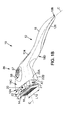
Figure 1A is a perspective view of the shaving razor according to the invention, the shaving cartridge carrier being in the shaving position and the shaving cartridge being released. -
Figure 1B is a perspective view of the razor shown inFigure 1A , the shaving cartridge carrier being in the shaving position and the shaving cartridge being connected to the shaving cartridge carrier. -
Figure 1C is a perspective view of the razor shown inFigure 1A , the shaving cartridge carrier being in the non-shaving position and the shaving cartridge being connected to the shaving cartridge carrier. -
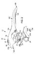
Figure 2 is a perspective view partially exploded of the razor shown inFigure 1A (without the shaving cartridge). -
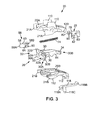
Figure 3 is an exploded perspective view of the shaving cartridge carrier shown inFigure 2 . -
Figure 4A is a partial perspective view of the shaving cartridge carrier shown inFigure 2 , the shaving cartridge being released from the shaving cartridge carrier. -
Figure 4B is a partial perspective view of the shaving cartridge carrier shown inFigure 2 , the shaving cartridge being connected to the shaving cartridge carrier. -
Figure 5 is a partial longitudinal section of the shaving razor carrier ofFigure 2 along line V-V. -
Figure 6A is a partial longitudinal section of the razor ofFigure 1A , the release-button being in the rest position. -
Figure 6B is a partial longitudinal section of the razor ofFigure 1A , the release-button being in the release position. -
Figure 6C is a partial perspective view of the control mechanism. -
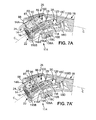
Figure 7A is a partial longitudinal section of the razor ofFigure 1C , the shaving cartridge carrier being in the non-shaving position and the release-button being in the rest position. -
Figure 7A' is a partial longitudinal section of the razor ofFigure 1C , the shaving cartridge carrier being in the non-shaving position and the control member being in the active position. -
Figure 7B is a partial longitudinal section of the razor ofFigure 1C , the shaving cartridge carrier being in the non-shaving position and the release-button being in the release position. -
Figure 7C is a partial longitudinal section of the razor ofFigure 1B , the shaving cartridge carrier being in the shaving position and the release-button being in the rest position. -
Figure 7C' is a partial longitudinal section of the razor ofFigure 1B , the shaving cartridge carrier being in the shaving position and the control member being in the active position. -
Figure 7D is a partial longitudinal section of the razor ofFigure 1A , the shaving cartridge carrier being in the shaving position and the release-button being in the release position. -
Figure 8 is a top view of the shaving razor ofFigure 1C . - In the various figures, the same references denote identical or similar elements.
-
Figure 1 illustrates arazor 10 according to the present invention, having arazor handle 12 and ashaving cartridge 14 provided with one orseveral shaving blades 16. - The
razor handle 12 has anelongate body 18 extending in a longitudinal direction L between afront end 18A and aback end 18B. Thebody 18 has anupper face 18C opposite to alower face 18D. - The
shaving cartridge 14 is preferably a disposable cartridge which can be connected to a shavingcartridge carrier 20 as illustrated onFigure 1B . - This
shaving cartridge carrier 20 is movable between a shaving position (depicted onFigure 1A or1B ) in which therazor cartridge carrier 20 and theshaving cartridge 14 extend at least partly out of ahousing 22 provided on thebody 18, and a non-shaving position (depicted onFigure 1C ) in which therazor cartridge carrier 20 and theshaving cartridge 14 are retracted inside thehousing 22. - The
housing 22 is hollow and preferably formed by anupper shell 22A and alower shell 22B as illustrated onFigure 2 which are maintained together in a well-known way like for example by snap-fitting or gluing. An opening 24 at thefront end 18A of thebody 18 allows access to the inside of thishollow housing 22. Especially, the shavingcartridge carrier 20 is movable through this opening 24. - In order to be able to connect or release the shaving
cartridge 14 especially in order to exchange it, thehandle 12 is further provided with arelease mechanism 26 provided on the shavingcartridge carrier 20. As illustrated in details onFigure 3 , therelease mechanism 26 includes an actuatingmember 28 which is adapted to actuate saidrelease mechanism 26 so as to release the shaving cartridge 14 (not illustrated) carried on said shavingcartridge carrier 20. - In reference to
Figures 3 ,4A and 4B , therelease mechanism 26 comprises twoarms shaving cartridge 14 to the shavingcartridge carrier 20. Thearms 30 are elastically biased opposite to one another toward a cartridge locking position (seeFigure 4B ) and movable toward one another into a cartridge release position (seeFigure 4A ). - Each
arm 30 has afirst end 30A including preferably ashell bearings 32 having a cylindrical concavefront face 32A and alateral edge 32B which protrudes outwardly and which has also a cylindrical shape. Thefront face 32A and thelateral edge 32B have the same cylindrical axis, corresponding to the axis of rotation A1 of theshaving cartridge 14. The twoarms first end 30A toward asecond end 30B. The medial axis X is substantially parallel to the curved longitudinal axis C of thehandle 12. The second ends 30B of the twoarms 30 may be connected together by ahinge 34, formed for instance as a thin bridge of plastic material connecting the twoarms 30 to each other when said arms are molded as a single piece. Thehinge 34 may have a negligible resilient action, or no resilient action, on the twoarms 30. - As shown in
figure 4A , therear face 14A of the shavingcartridge 14 may include two inwardly facingarcuate slots 36 shaped in correspondence with thelateral edges 32B of theshell bearings 32 and adapted to receive saidlateral edges 32B for pivotally mounting the shavingcartridge 14 onto thehandle 12. Thesearcuate slots 36 may be formed respectively in two protrudingribs 38 and may be limited toward thehandle 12, by a first arcuateconcave surface 40 facing toward the shavingcartridge 14, and away from thehandle 12, by a larger second arcuateconvex surface 42 facing toward thehandle 12. - When the shaving
cartridge 14 is connected to the shavingcartridge carrier 20, these rearwardly protrudingribs 38 are partly covered by twolateral flanges 21 provided on the razor handle 12. More specifically thelateral flanges 21 can be provided on the shavingcartridge carrier 20 and extend forward at thefront end 18A of thehandle body 18 in the direction of the shavingcartridge 14, at least as far as the twoarms 30, thearms 30 being situated between said twolateral flanges 21. The rearwardly protrudingribs 38 and thelateral flanges 21 are preferably shaped in correspondence to partly cover said protrudingribs 38. - These
lateral flanges 21 improve the retention of the shavinghead 14 on the razor handle 12 and guide the user during the connection of the shaving cartridge on the razor handle 12. Besides, the movement generated by the shaving in the connection can be at least partly absorbed by theflanges 21. The front faces 32A of theshell bearings 32 bear respectively on the second arcuate convex surfaces 42. Said second arcuateconvex surfaces 42 may include respectively twonotches 44 for receivingcorresponding protrusions 46 of theshell bearings 32, so as to limit the angular range of rotation of the shavingcartridge 14. Therear face 14A of the shavingcartridge 14 may further include acentral rib 48 having an edge forming atop cam surface 50 facing away from the shavingcartridge 14 toward thehandle 12. Thecam surface 50 may have a generally V shape and may include two substantiallyflat surfaces 52 which are slightly inclined relative to one another and which may be for instance separated from one another by anotch 54 hollowed out in therib 48 in order to adapt the shavingcartridge 14 on a other type of handle having a flexible tongue which is inserted into saidnotch 54. - In reference to
Figures 3 and5 , therelease mechanism 26 further includes aplunger 56 which is movably mounted, substantially along the medial axis X between the twoarms 30. Thisplunger 56 has acentral body 58 and twolateral wings 60 extending opposite to one another toward the twoarms 30. Thecentral body 58 extends longitudinally parallel to the medial axis X, between a first, substantially flatfree end 58A which bears against thecam surface 50 of the shaving cartridge 14 (seeFigure 4A ), and asecond end 58B facing away from the shavingcartridge 14. - A
recess 62 may be hollowed out in thecentral body 58, saidrecess 62 forming a blind hole which opens at thesecond end 58B of thecentral body 58, in the direction of thehandle 12. Eachlateral wing 60 may include adetent 64 protruding parallel to the medial axis X toward the shavingcartridge 14, saiddetent 64 facing an inwardly extendingprotrusion 66 belonging to thecorresponding arm 30. Theprotrusion 66 has anopening 68 which is limited inwardly by arim 70 belonging to saidprotrusion 66. Besides, thelateral wings 60 of theplunger 56 may each have respectively tworibs 72 which extend in a medial plane of thearms 30, opposite to thecentral body 58. - The
plunger 56 is elastically biased toward thecam surface 50 of the shavingcartridge 14 so as to cooperate therewith by camming action to bias said shavingcartridge 14 in rotation toward a rest position. In the example shown in the figures, theplunger 56 is elastically biased by ahelicoidal spring 74, which has a first spring end fitted into therecess 62 and a second spring end fitted into arecess 76, for instance in the form of a blind hole, hollowed out in the actuatingmember 28. - The actuating
member 28 is disposed between thearms 30 in line with theplunger 56 along the medial axis X. Said actuatingmember 28 is disposed between theplunger 56 and thehinge 34 along the medial axis X. Therecess 76 opens parallel to the medial axis X toward theplunger 56. - The actuating
member 28 is slidably mounted between thearms 30, substantially parallel to the medial axis X and is elastically biased by saidspring 74 toward thehandle 12, i.e. away from the shavingcartridge 14. Said actuatingmember 28 cooperates by camming action with the twoarms 30 for biasing saidarms 30 outwardly away from each other, toward a cartridge locking position shown inFigure 4B , wherelateral edges 32B of theshell bearings 32 penetrate in the correspondingarcuate slots 36 of the shavingcartridge 14. - The actuating
member 28 has preferably acentral body 78 in which therecess 76 is hollowed out, and twolateral extensions 80 extending opposite to one another toward the twoarms 30 and cooperating by camming action respectively with said twoarms 30 for biasing the arms toward the cartridge locking position. Theselateral extensions 80 are provided with a respective pin 82 (seeFigures 3 and5 ) slidably engaged in two respective cam-recesses 84 provided on thearms 30 and formed to allow the biasing of the arms toward the head locking position when the actuating member is pushed toward the front end of the body. Said cam-recesses 84 may be diverging from the medial axis X in a direction away from thehandle 12. - Thanks to these dispositions, the
same spring 74 is used to bias theplunger 56 elastically toward thecam surface 50 of the shavingcartridge 14 and to bias the actuatingmember 28 away from the shavingcartridge 14, thus biasing both the shavingcartridge 14 in rotation toward the rest position and thearms 30 toward the cartridge lock position. It should be noted that theplunger 56 is maintained between the twoarms 30 both by cooperation with thespring 74 by abutment against thecam surface 50 of the shavingcartridge 14 and eventually by abutment against theprotrusions 66 of thearms 30. - Referring back to
Figure 1 , the razor handle 12 is further provided with acontrol mechanism 86 which is disposed on thebody 18 for controlling the actuatingmember 28. - The
control mechanism 86 comprises a release-button 88 movably mounted on theelongate body 18 between a rest position illustrated onFigure 6A and a release position illustrated onFigure 6B . - The release-
button 88 may be slidably mounted in the longitudinal direction L on theelongate body 18 between the rest position and the release position, said release position being closer to thefront end 18A of theelongate body 18 than said rest position. In the example shown in the figures, the release-button 88 is elastically biased by ahelicoidal spring 89, which has a first spring end fitted around alug 92 provided on thebody 18 and a second spring end fitted around alug 94 provided on the release-button 88. The release-button 88 is thus elastically biased by saidspring 89 toward thehandle 12, i.e. away from the shavingcartridge 14, in its rest position (Figure 6A ). - The
control mechanism 86 further comprises acontrol member 90 movably mounted on the release-button 88 between a retracted position illustrated onFigure 6A and an active position illustrated onFigure 6B . As disclosed in details hereafter and in reference toFigures 7A-7D , thiscontrol member 90 is able to push the actuatingmember 28 according to its position: in its retracted position, thecontrol member 90 does not interfere with the actuatingmember 28 and in its active position, thecontrol member 90 is positioned to be able to act on said actuatingmember 28 in pushing it toward thefront end 18A of thebody 18. - In reference to
Figures 6A-6C , thecontrol member 90 is pivotally mounted on the release-button 88 via twoopposite pivots 96 provided on thecontrol member 90 and lodged in corresponding swing-holes 98 provided on the release-button 88. - The
elongate body 18 further includes aguide 100 adapted for guiding thecontrol member 90 so that it is in the retracted position (Figure 6A ) when the release-button 88 is in the rest position and in the active position (Figure 6B ) when the release-button 88 is in the release position. To this extent, theguide 100 has asurface 102 along which twoopposite hubs 104 provided on thecontrol member 90 are able to slide. Theguide 100 has also agroove 106 in which thehubs 104 are located when thecontrol member 90 is in its retracted position (Figure 6A ). Thisgroove 106 is located in the rear of the surface 102 (opposite to thefront end 18A of the body 18) and tilts thefree end 90A of thecontrol member 90 toward the top (toward the release-button 88). - When the release-
button 88 slides forward (toward thefront end 18A) toward its release position, thehubs 104 leave thegroove 106 and slide along thesurface 102 parallel to the longitudinal direction L, such that thecontrol member 90 pivots about thehubs 104 and itsfree end 90A tilts toward the bottom (opposite to release-button 88) deviating from the release-button 88 (seeFigure 6B ) of a tilting angle α comprised between 15° and 30°, preferably of about 17.5°. - The value of this tilting angle α is chosen according to the curvature of the handle, such that the
front end 90A of thecontrol member 90 is positioned to act on said actuatingmember 28 when the shavingcartridge carrier 20 is in the shaving position. - As illustrated in
Figures 7A to 7D , according to the position of the shavingcartridge carrier 20, thecontrol member 90 and especially itsfree end 90A is or not in register with the actuatingmember 28. - When the
control member 90 is in its rest position (the release-button 88 being in its rest-position), the shavingcartridge carrier 20 being in its non-shaving position as illustrated onFigure 7A or in its shaving position as illustrated onFigure 7C , the free end of thecontrol member 90 is lifted up and distant from the shavingcartridge carrier 20 and can thus not act on it. - When the release-
button 88 slides toward its release-position, thecontrol member 90 pivots in its active position (Figure 7A' or 7C' ) and thefree end 90A of thecontrol member 90 is tilted toward the shavingcartridge carrier 20. - In this case, when the shaving
cartridge carrier 20 is in its non-shaving position as illustrated onFigure 7B , thecontrol member 90 can still not act on it. In fact, the free end of thecontrol member 90 is located above the shavingcartridge carrier 20 and thecontrol member 90 slides with it without pushing any member. In the release-position, thefree end 90A of thecontrol member 90 is just back the shaving cartridge 14 (without contact). - When the shaving
cartridge carrier 20 is in its shaving position as illustrated onFigure 7D , thecontrol member 90 can act on it. In fact, thefree end 90A of thecontrol member 90 is located in register with the shavingcartridge carrier 20. Thus, when the release-button 88 continues to slide toward its release-position thecontrol member 90 slides with it and pushes the actuatingmember 28 forward toward thefront end 18A of thebody 18. Consequently, the shavingcartridge 14 is released as above-explained. - In fact, coming back to
Figure 4A-4C , when a shavingcartridge 14 is mounted on thehandle 12, therelease mechanism 26 is normally in the cartridge lock position. Starting from this position, when a user wishes to exchange shaving heads, he first pushes the release-button 88 forward, which brings thearm 30 toward each other against the camming action of the actuatingmember 28. During this movement, the actuatingmember 28 slides along the medial axis X toward theplunger 56, and said actuatingmember 28 partially penetrates between theribs 72 of the plunger. When thearms 30 have sufficiently moved toward each other to reach the cartridge release position shown infigure 4A , the shavingcartridge 14 is released by theshell bearings 32 and is simultaneously ejected by theplunger 56. - The
plunger 56 then moves forward to an outwardly protruding position, so that thedetents 64 of said plunger penetrate in therecesses 68 of theextensions 66 of the arms. In this position, thearms 30 are maintained in the cartridge release position by abutment of therims 70 against saiddetents 64, thus cooperating by hooking action. Afterwards, when anew shaving cartridge 14 is fixed to thehandle 12, theshell bearings 32 are inserted between thearcuate slots 36 of thenew shaving cartridge 14 and thecam surface 50 of saidnew shaving cartridge 14 pushes theplunger 56 backward toward thehandle 12. Thearms 30 are then released and deviate away from each other under the action of the actuatingmember 28, so that theshell bearings 32 insert themselves in thearcuate slots 36 of thenew shaving cartridge 14, and therelease mechanism 26 is again in the position shown inFigures 4B ,7A and7C . - As illustrated on the Figures, the release-
button 88 may be provided on theupper face 18C of thebody 18 and afinger rest pad 87 can be further provided on the upper face of the body near the release-button 88. Thus, when a user wanted to release the shavingcartridge 14, he has just to put one of his fingers on thefinger rest pad 108 and slide his finger forward, toward thefront end 18A of thebody 18, to push the release-button 88 toward its release position. - The razor handle 12 further comprises a carrier-
button 108 slidably mounted in the longitudinal direction L for controlling the shavingcartridge carrier 20 motion. This carrier-button 108, preferably provided on thelower face 18D of thebody 18, is movable between a first position (seeFigures 7A, 7A' and7B ) in which theshaving cartridge carrier 20 is in said non-shaving position and a second position (seeFigures 7C, 7C' and7D ) in which theshaving cartridge carrier 20 is in said shaving position. The second position of the carrier-button 108 may be closer to thefront end 18A of theelongate body 18 than the first position. - Consequently, when a user wants to shave, he has just to push the carrier-
button 108 forward, toward its second position and the shavingcartridge carrier 20 slides toward thefront end 18A through theopening 24 until it reaches its shaving position (seeFigure 1B ). - As illustrated on
Figures 2 and3 , the release-mechanism 26 may be partly confined inside the shavingcartridge carrier 20 formed by anupper part 20A assembled to alower part 20B. In this case, thelateral flanges 21 are also formed in two correspondingparts upper part 20A and on thelower part 20B. - The shaving
cartridge carrier 20 may have guide wings in order to guide its sliding inside thehousing 22 along longitudinal direction L. In particular, twoupper guide wings 110 can be provided on theupper part 20A and engaged in two corresponding longitudinal rails (not illustrated) provided on the inner surface of theupper shell 22A of thehousing 22. Besides, threelower guide wings 112 can also be provided on thelower part 20B of the shavingcartridge carrier 20 and engaged in three corresponding longitudinal rails (not illustrated) provided on the inner surface of thelower shell 22B of thehousing 22. - The razor handle 12 further comprises a
locking mechanism 114 adapted to lock theshaving cartridge carrier 20 either in its non-shaving or in its shaving position. The carrier-button 108 may be able to actuate thelocking mechanism 114 to unlock the shavingcartridge carrier 20 from said non-shaving position or from said shaving position. - The
locking mechanism 114 may comprise tworecesses housing 22, for example in thelower face 18A of the razor handle, and aspring tongue 118 connected to the carrier-button 108 and to the shavingcartridge carrier 20. Thespring tongue 118 has afree end 118A which can be retained in one of the tworecesses spring tongue 118 has an oppositefree end 118B which is engaged in arecess 120 provided on theupper part 20A of the shavingcartridge carrier 20. - The
spring tongue 118 has further amiddle extension 118C on which the carrier-button 108 is fixed. In fact, the carrier-button 108 has a central ablind hole 108A in which themiddle extension 118C is engaged. It follows that when the carrier-button 108 is slid toward its second position, thespring tongue 118 is also moved forward and the shavingcartridge carrier 20 slides toward its shaving position (Figures 7C and7D ). In order to unlock the shavingcartridge carrier 20 from its non-shaving or shaving position, the carrier-button 108 has to be pushed toward the inside of thehousing 22 in order to release thefree end 118A from thecorresponding recess - The
spring tongue 118 may be preloaded before mounting in the razor handle such that it is elastically brought back against the corresponding recess or thelower face 18A, when the carrier-button 108 is released. - Hence, when the shaving
cartridge carrier 20 is in its non-shaving position (seeFigure 7A and7B ), thefree end 118A is located in therecess 116A, whereas when the shavingcartridge carrier 20 is in its shaving position (seeFigure 7C and7D ), thefree end 118A is located in therecess 116B, saidrecess 116B being closer to thefront end 18A than saidrecess 116A. - In order to be able to release a shaving cartridge has disclosed previously with help of the release-
button 88, the shavingcartridge carrier 20 has to be in its shaving position. - In fact, when the release-
button 88 begun to be slide forward, thecontrol member 90 pivots from its retracted position (Figure 7A ) to its active position (Figure 7A' ). However, when shavingcartridge carrier 20 is in its non-shaving position (the shavingcartridge 14 is located inside the housing 22) as depicted in details onFigures 7A-7B , even when the release-button 88 continue to be slid forward toward its release position (Figure7B ), thecontrol member 90 is neither able to contact, nor to push forward the actuatingmember 28 of the shavingcartridge carrier 20. In fact, the actuatingmember 28 is located too backward relative to thefree end 90A of thecontrol member 90. Consequently, the shaving cartridge can not be released. - On the contrary, when the shaving
cartridge carrier 20 is previously put in its shaving position (the shavingcartridge 14 is located outside the housing 22) as depicted in details onFigures 7C-7D and the release-button 88 begun to be slide forward, thecontrol member 90 pivots from its retracted position (Figure 7C ) to its active position (Figure 7C' ) and itsfree end 90A arrives just behind the actuatingmember 28. Hence, when the release-button 88 continue to be slid forward toward its release position (Figure7D ), thecontrol member 90 slide forward and push the actuatingmember 28 of the shavingcartridge carrier 20 toward thefront end 18A of therazor body 18. Consequently, as explained in details above, the shavingcartridge 14 is released. - Thus, to release a shaving
cartridge 14 connected to the razor handle 12, a user has to push and slide forward the carrier-button 108 (for example with its thumb) in order to bring the shavingcartridge carrier 20 out of thehousing 22 and then he has to slide forward the release-button 88 (for example with its index) to release the shaving cartridge. - The
elongate body 18 may define a variable width W along the length L thereof. As depicted onFigures 8A and8B , said body comprising an enlarged part Ep having a width W1 and a slim part Sp having a width W2 connected together by aneck 122. The enlarged part Ep extends from thisneck 122 to thefront end 18A, whereas the slim part Sp extends from theback end 18B to thisneck 122. - Due to the geometry of the body, the
neck 122 has a widening shape which is broader on the side of the enlarged part Ep, the widenside 122A of the neck being located at about 15% of the overall length L from thefront end 18A. For example, with a length L of theelongate body 18 comprised between 100 mm and 180 mm, preferably about 150 mm, theneck 122 is located between 20 mm to 40 mm from thefront end 18A, preferably at about 30 mm. - Besides, the length L122 of the
neck 122 and its widening are chosen according to the widths W1 and W2 such that the connection between theneck 122, the enlarged part Ep and the slim part Sp has a smooth curvature. Theneck 122 has for example a length L122 comprised between 20 mm and 40 mm, preferably about 30 mm. - The width W1 of the enlarged part Ep may be sensitively constant along the length thereof and have a value which is just superior to the length L14 of a shaving
cartridge 14. The width W1 may be comprised between 40 mm and 50 mm, preferably 45 mm. - The width W2 of the slim part Sp may be variable along the length thereof. Especially, the slim part can comprise two parts: a first one Sp1 connected to the
neck 122 which is slimmer than a second one Sp2 extending from theback end 18B. The first slim part Sp1 can be provided with afinger rest area 124 on theupper face 18C of the body, and the second slim part Sp2 can be provided with afinger rest area 126 on thelower face 18D of the body (seeFigure 8B ), saidfinger rest areas
Claims (12)
- A razor handle for a retractable shaving cartridge (14) comprising:an elongate body (18) extending in a longitudinal direction (C) between a front end (18A) and a back end (18B) and having an upper (18C) and a lower (18D) face, said body (18) having a hollow housing (22) provided with an opening at the front end (18A) of the body (18),a shaving cartridge carrier (20) movable between a shaving position in which the razor cartridge carrier (20) extends at least partly out of the housing (22), and a non-shaving position in which the razor cartridge carrier (20) is retracted inside the housing (22),a release mechanism (26) provided on the shaving cartridge carrier (20) and including an actuating member (28) which is adapted to actuate said release mechanism (26) so as to release a shaving cartridge (14) carried by said shaving cartridge carrier (20), anda control mechanism (86) which is disposed on the body (18) for controlling the actuating member (28) only when the shaving cartridge carrier (20) is in said shaving position, said control mechanism (86) comprising a release-button (88) movably mounted on the elongate body (18) between a rest position and a release position, said control mechanism (86) further comprising a control member (90) movably mounted between a retracted position in which the control member (90) does not interfere with the actuating member (28) of the release mechanism (26) and an active position in which the control member (90) is positioned to act on said actuating member (28) upon actuation of the release-button (88) when the shaving cartridge carrier (20) is in the shaving position,characterized in that the control member (90) is movably mounted on the release-button (88), andin that the elongate body (18) further includes at least a guide (100) adapted for guiding the control member (90) so that said control member (90) be in the retracted position when the release-button (88) is in the rest position and in the active position when the release-button (88) is in the release position.
- Razor handle according to claim 1, wherein the release-button (88) is slidably mounted in the longitudinal direction (C) on the elongate body (18) between the rest position and the release position, said release position being closer to the front end (18A) of the elongate body (18) than said rest position and said release-button (88) being elastically biased toward said back end (18B), said control member (90) being pivotally mounted relative to said release-button (88) between the retracted position and the active position in which the control member (90) is positioned to push said actuating member (28) toward the front end (18A) of the body (18).
- Razor handle according to claim 2, wherein the release mechanism (26) comprises two arms (30) for connecting a shaving cartridge (14) to the shaving cartridge carrier (20), said arms (30) extending substantially symmetrically on both sides of a medial axis (X), said arms (30) being elastically biased opposite to one another toward a cartridge locking position and movable toward one another into a cartridge release position, and wherein the actuating member (28) has two pins (82) slidably engaged in two cam-recesses (84) provided on the arms (30) and formed to allow the biasing of the arms (30) toward the head locking position when the actuating member (28) is pushed toward the front end (18A) of the body (18).
- Razor handle according to the preceding claim, wherein the razor cartridge carrier (20) further comprises lateral flanges (21) extending forward at the front end (18A) of the body (18), at least as far as said two arms (30), said two arms (30) being situated between said two lateral flanges (21).
- Razor handle according to anyone of the preceding claims, further comprising a carrier-button (108) which is slidably mounted in the longitudinal direction (C) on the elongate body (18) for controlling the shaving cartridge carrier (20) motion, said carrier-button (108) being movable between a first position in which the shaving cartridge carrier (20) is in said non-shaving position and a second position in which the shaving cartridge carrier (20) is in said shaving position, said second position being closer to the front end (18A) of the elongate body (18) than said first position.
- Razor handle according to the preceding claim, wherein the release-button (88) is provided on the upper face of the body (18), whereas the carrier-button (108) is provided on the lower face of the body (18), and wherein a finger rest pad (87) is provided on the upper face (18C) of the body (18) near the release-button (88).
- Razor handle according to claim 4 or 5, further comprising a locking mechanism (114) adapted to lock the shaving cartridge carrier (20) either in said non-shaving or in said shaving position, said carrier-button (108) being able to actuate the locking mechanism (114) to unlock the shaving cartridge carrier (20) from said non-shaving position or from said shaving position.
- Razor handle according to the preceding claim, wherein the locking mechanism (114) comprises two recesses (116A, 116B) provided on the housing (22) and a spring tongue (118) connected to the carrier-button (108) and to the shaving cartridge carrier (20), said spring tongue (118) having a free end (118A) which is retained in one of the two recesses (116A) when the shaving cartridge carrier (20) is in said non-shaving, and in the other of the two recesses (116B) when the shaving cartridge carrier (20) is in said shaving position.
- Razor handle according to anyone of the preceding claims, wherein the body (18) has a variable width (W1, W2) along a length (L), said body (18) comprising an enlarged part (Ep) and a slim part (Sp) connected together by a neck (122), said neck (122) being located at a distance of the front end (18A) which is comprised between 10% and 20% of an overall length (L) of said razor handle (12), the enlarged part (Ep) extending from this neck (122) to the front end (18A), whereas the slim part (Sp) extends from the back end (18B) to this neck (122).
- A razor comprising a razor handle (12) according to any of the preceding claims and a shaving cartridge (14) connected to the shaving cartridge carrier (20).
- Razor according to the preceding claim, wherein the shaving cartridge (14) is connected to the shaving cartridge carrier (20) such that the shaving cartridge (14) extends out of the razor handle (12) when the shaving cartridge carrier (20) is in the shaving position and the shaving cartridge (14) is located inside the housing (22) when the shaving cartridge carrier (20) is in the non-shaving position, and wherein the release mechanism (26) is adapted to release the shaving cartridge (14) only when the shaving cartridge carrier (20) is in said shaving position.
- Razor according to the claim 10 or 11, wherein the shaving cartridge (14) is provided with rearwardly protruding ribs (38) connected to the razor handle (12) and partly covered by the two lateral flanges (21) of the razor handle (12) when the shaving cartridge (14) is connected to the shaving cartridge carrier (20).
Applications Claiming Priority (1)
| Application Number | Priority Date | Filing Date | Title |
|---|---|---|---|
| PCT/EP2008/054439 WO2009124597A1 (en) | 2008-04-11 | 2008-04-11 | Razor handle for a retractable shaving cartridge and a razor comprising such a razor handle |
Publications (2)
| Publication Number | Publication Date |
|---|---|
| EP2265422A1 EP2265422A1 (en) | 2010-12-29 |
| EP2265422B1 true EP2265422B1 (en) | 2013-06-12 |
Family
ID=40224030
Family Applications (1)
| Application Number | Title | Priority Date | Filing Date |
|---|---|---|---|
| EP08736148.1A Not-in-force EP2265422B1 (en) | 2008-04-11 | 2008-04-11 | Razor handle for a retractable shaving cartridge and a razor comprising such a razor handle |
Country Status (6)
| Country | Link |
|---|---|
| US (1) | US8844145B2 (en) |
| EP (1) | EP2265422B1 (en) |
| BR (1) | BRPI0822615A2 (en) |
| CA (1) | CA2721018C (en) |
| MX (1) | MX2010011155A (en) |
| WO (1) | WO2009124597A1 (en) |
Families Citing this family (63)
| Publication number | Priority date | Publication date | Assignee | Title |
|---|---|---|---|---|
| EP2265422B1 (en) | 2008-04-11 | 2013-06-12 | BIC Violex S.A. | Razor handle for a retractable shaving cartridge and a razor comprising such a razor handle |
| JP5599800B2 (en) * | 2008-09-18 | 2014-10-01 | ビック・バイオレクス・エス・エー | Razor with retractable shaving cartridge and razor handle for such handle |
| US8671577B2 (en) * | 2008-12-03 | 2014-03-18 | Thomas A. Brown | Razor with independent suspension |
| PL2614938T3 (en) | 2012-01-12 | 2020-06-29 | Spectrum Brands, Inc. | Electric hair trimmer |
| US9283685B2 (en) | 2012-07-26 | 2016-03-15 | Shavelogic, Inc. | Pivoting razors |
| US9486930B2 (en) | 2012-09-27 | 2016-11-08 | Shavelogic, Inc. | Shaving systems |
| WO2014051842A1 (en) | 2012-09-27 | 2014-04-03 | Shavelogic, Inc. | Shaving systems |
| WO2014051843A1 (en) | 2012-09-28 | 2014-04-03 | Shavelogic, Inc. | Shaving systems |
| US9623575B2 (en) | 2012-12-18 | 2017-04-18 | Shavelogic, Inc. | Shaving systems |
| BR112015013766B1 (en) * | 2012-12-21 | 2021-10-13 | Bic-Violex Sa | SHAVING AND HEAD AND CABLE ASSEMBLY FOR A SHAVING |
| MX360046B (en) * | 2012-12-21 | 2018-10-19 | Bic Violex Sa | Shaver. |
| US20150158192A1 (en) | 2013-12-09 | 2015-06-11 | Shavelogic, Inc. | Multi-material pivot return for shaving systems |
| WO2015142663A1 (en) | 2014-03-21 | 2015-09-24 | Shavelogic, Inc. | Metal spring return |
| JP6502487B2 (en) | 2014-10-10 | 2019-04-17 | エッジウェル パーソナル ケア ブランズ リミテッド ライアビリティ カンパニーEdgewell Personal Care Brands, LLC | Universal razor cartridge handle |
| RU2681234C2 (en) * | 2014-12-05 | 2019-03-05 | Бик-Виолекс Са | Shaver handle with mechanism of fixation and disconnection for connection and disconnection of the cassette of shave |
| GB201500491D0 (en) * | 2015-01-13 | 2015-02-25 | Rathbone Razor Ltd | Disposable razor |
| US20170087733A1 (en) * | 2015-09-29 | 2017-03-30 | The Gillette Company | Kit Comprising A Razor Cartridge And An Adapter |
| US10131063B2 (en) * | 2015-09-29 | 2018-11-20 | The Gillette Company Llc | Adapter for attaching a razor cartridge to a razor handle |
| DE102016101672A1 (en) * | 2016-01-29 | 2017-08-03 | Beiersdorf Aktiengesellschaft | Nassrasiergriff |
| US10987820B2 (en) | 2016-02-12 | 2021-04-27 | Peter Alexander Gegg | Adjustable body shaver, system and method |
| USD765912S1 (en) | 2016-03-23 | 2016-09-06 | Phan Thi Minh Vinh | Razor handle |
| BR112018069841A2 (en) | 2016-04-01 | 2019-01-29 | Procter & Gamble | mouthwash compositions containing a gel mesh phase |
| CN108883542B (en) * | 2016-04-05 | 2020-02-14 | 比克-维尔莱克 | Razor handle with lock and release mechanism for engaging and disengaging a shaving cartridge |
| US10652956B2 (en) | 2016-06-22 | 2020-05-12 | The Gillette Company Llc | Personal consumer product with thermal control circuitry and methods thereof |
| USD818643S1 (en) * | 2016-07-13 | 2018-05-22 | Edgewell Personal Care Brands, Llc. | Razor Actuator Button |
| USD802842S1 (en) | 2017-03-15 | 2017-11-14 | Vu Phan Quang Ngo | Safety razor handle |
| US11141873B2 (en) * | 2017-04-18 | 2021-10-12 | The Gillette Company Llc | Shaving razor system |
| US20180297221A1 (en) * | 2017-04-18 | 2018-10-18 | The Gillette Company Llc | Shaving razor system and method of manufacture |
| US20180297225A1 (en) * | 2017-04-18 | 2018-10-18 | The Gillette Company Llc | Shaving razor system and method of manufacture |
| US20180297222A1 (en) * | 2017-04-18 | 2018-10-18 | The Gillette Company Llc | Shaving razor system |
| US10807261B2 (en) | 2017-06-21 | 2020-10-20 | Harry's, Inc. | Razor handle |
| USD815776S1 (en) | 2017-10-08 | 2018-04-17 | Vu Phan Quang Ngo | Safety razor |
| WO2019108392A1 (en) * | 2017-11-28 | 2019-06-06 | Edgewell Personal Care Brands, Llc | Razor handle |
| USD870970S1 (en) | 2018-03-09 | 2019-12-24 | Personal Care Marketing And Research, Inc. | Razor handle |
| USD886382S1 (en) | 2018-03-09 | 2020-06-02 | PCMR International Ltd. | Razor handle |
| USD870971S1 (en) | 2018-03-09 | 2019-12-24 | Personal Care Marketing And Research, Inc. | Razor handle |
| US11607820B2 (en) | 2018-03-30 | 2023-03-21 | The Gillette Company Llc | Razor handle with movable members |
| JP7090727B2 (en) | 2018-03-30 | 2022-06-24 | ザ ジレット カンパニー リミテッド ライアビリティ カンパニー | Razor handle with pivot part |
| BR112020020132A2 (en) | 2018-03-30 | 2021-01-05 | The Gillette Company Llc | HANDLE OF SHAVING OR DEVILING APPLIANCE WITH MOBILE LIMBS |
| WO2019190962A1 (en) | 2018-03-30 | 2019-10-03 | The Gillette Company Llc | Razor handle with a pivoting portion |
| CN111819047B (en) | 2018-03-30 | 2022-11-08 | 吉列有限责任公司 | Razor handle with movable member |
| WO2019190911A1 (en) | 2018-03-30 | 2019-10-03 | The Gillette Company Llc | Shaving razor system |
| US12240135B2 (en) | 2018-03-30 | 2025-03-04 | The Gillette Company Llc | Razor handle with a pivoting portion |
| EP3546156B1 (en) | 2018-03-30 | 2021-03-10 | The Gillette Company LLC | Razor handle with a pivoting portion |
| BR112020020117A2 (en) | 2018-03-30 | 2021-01-26 | The Gillette Company Llc | shaving or shaving cartridge |
| JP2021516102A (en) | 2018-03-30 | 2021-07-01 | ザ ジレット カンパニー リミテッド ライアビリティ カンパニーThe Gillette Company Llc | Razor handle with pivot part |
| WO2019191231A1 (en) | 2018-03-30 | 2019-10-03 | The Gillette Company Llc | Razor handle with a pivoting portion |
| USD874061S1 (en) | 2018-03-30 | 2020-01-28 | The Gillette Company Llc | Shaving razor cartridge |
| EP3775633B1 (en) * | 2018-03-30 | 2024-08-21 | The Gillette Company LLC | Razor handle with movable members |
| WO2019191345A1 (en) | 2018-03-30 | 2019-10-03 | The Gillette Company Llc | Razor handle with a pivoting portion |
| JP2021516136A (en) | 2018-03-30 | 2021-07-01 | ザ ジレット カンパニー リミテッド ライアビリティ カンパニーThe Gillette Company Llc | Razor handle with movable members |
| US11345055B2 (en) | 2018-09-05 | 2022-05-31 | The Gillette Company Llc | Razor cartridge structure |
| US11298842B2 (en) * | 2018-09-05 | 2022-04-12 | The Gillette Company Llc | Razor structure |
| US11020866B2 (en) * | 2019-03-15 | 2021-06-01 | The Gillette Company Llc | Handle for a razor |
| WO2021076116A1 (en) | 2019-10-16 | 2021-04-22 | Yigal Mesika | Shaving apparatus having a razor handle for disposable razor cartridges |
| USD940956S1 (en) | 2019-10-16 | 2022-01-11 | Yigal Mesika | Razor handle |
| USD977868S1 (en) | 2019-10-16 | 2023-02-14 | Yigal Mesika | Razor stand |
| USD1036777S1 (en) | 2022-06-30 | 2024-07-23 | Dollar Shave Club, Inc. | Razor handle |
| USD1037564S1 (en) | 2022-06-30 | 2024-07-30 | Dollar Shave Club, Inc. | Razor handle |
| USD1051500S1 (en) | 2023-03-08 | 2024-11-12 | Dollar Shave Club, Inc. | Razor handle |
| USD1052181S1 (en) | 2023-03-08 | 2024-11-19 | Dollar Shave Club, Inc. | Razor handle |
| WO2024205278A1 (en) * | 2023-03-28 | 2024-10-03 | 주식회사 도루코 | Razor assembly |
| WO2025155577A1 (en) | 2024-01-19 | 2025-07-24 | The Gillette Company Llc | Shaving razor system |
Family Cites Families (19)
| Publication number | Priority date | Publication date | Assignee | Title |
|---|---|---|---|---|
| US3795979A (en) | 1972-04-27 | 1974-03-12 | Gillette Co | Handle |
| NL7405802A (en) | 1974-05-01 | 1975-11-04 | Philips Nv | DRY SHAVER WITH EXTENDABLE CLIPPER. |
| GB2116470B (en) | 1982-03-12 | 1985-09-25 | Gillette Co | Safety razors |
| US4504707A (en) * | 1982-03-15 | 1985-03-12 | Kyushu Hitachi Maxell, Ltd. | Push-button switch locking device for use in electric appliance |
| AU638974B2 (en) * | 1989-06-05 | 1993-07-15 | Warner-Lambert Company | Razor mechanism |
| US5157834A (en) * | 1990-04-10 | 1992-10-27 | Warner-Lambert Company | Razor mechanism with slidable cartridge support |
| GB9208098D0 (en) * | 1992-04-13 | 1992-05-27 | Gillette Co | Razor with movable cartridge |
| US5206994A (en) * | 1992-06-04 | 1993-05-04 | Catherine Lin | Collapsible razor |
| US5465488A (en) * | 1994-12-23 | 1995-11-14 | Yaw; Ke G. | Folding razor |
| US5608972A (en) * | 1995-11-24 | 1997-03-11 | Tsae-Chyn; Chern | Stretching and contracting razor case |
| KR100352838B1 (en) * | 2000-06-24 | 2002-09-16 | 주식회사 도루코 | Shaver |
| DE202004001085U1 (en) | 2004-01-23 | 2004-06-09 | Heide, Heike Van Der | Wet contour razor has two connected holders with shaving head at one end and guide with slide and fasteners for a miniature shaving head at the other end |
| US6968623B2 (en) * | 2002-06-21 | 2005-11-29 | Andis Company | Hair trimmer with adjustable comb |
| US7611013B2 (en) * | 2002-12-24 | 2009-11-03 | Clio Designs, Inc. | Retractable razor assembly and packaging system for same |
| DE10310163A1 (en) * | 2003-03-08 | 2004-09-16 | Braun Gmbh | slide switches |
| WO2005090016A1 (en) * | 2004-03-15 | 2005-09-29 | Bic-Violex Sa | Razor having two silideable shaving heads |
| EP1789238B1 (en) * | 2004-09-07 | 2008-03-19 | BIC Violex S.A. | Razor handle and shaver including such a handle |
| US7093363B1 (en) * | 2005-07-12 | 2006-08-22 | Kuo Jack C | Foldable razor assembly |
| EP2265422B1 (en) | 2008-04-11 | 2013-06-12 | BIC Violex S.A. | Razor handle for a retractable shaving cartridge and a razor comprising such a razor handle |
-
2008
- 2008-04-11 EP EP08736148.1A patent/EP2265422B1/en not_active Not-in-force
- 2008-04-11 US US12/937,292 patent/US8844145B2/en active Active
- 2008-04-11 CA CA2721018A patent/CA2721018C/en not_active Expired - Fee Related
- 2008-04-11 WO PCT/EP2008/054439 patent/WO2009124597A1/en not_active Ceased
- 2008-04-11 BR BRPI0822615-6A patent/BRPI0822615A2/en not_active IP Right Cessation
- 2008-04-11 MX MX2010011155A patent/MX2010011155A/en active IP Right Grant
Also Published As
| Publication number | Publication date |
|---|---|
| MX2010011155A (en) | 2011-04-27 |
| BRPI0822615A2 (en) | 2015-06-23 |
| WO2009124597A1 (en) | 2009-10-15 |
| EP2265422A1 (en) | 2010-12-29 |
| US20110023310A1 (en) | 2011-02-03 |
| CA2721018A1 (en) | 2009-10-15 |
| CA2721018C (en) | 2014-02-25 |
| US8844145B2 (en) | 2014-09-30 |
Similar Documents
| Publication | Publication Date | Title |
|---|---|---|
| CA2721018C (en) | Razor handle for a retractable shaving cartridge and a razor comprising such a razor handle | |
| US20230364817A1 (en) | Razor cartridge | |
| US8732965B2 (en) | Razor handles to be releasably connected to shaving cartridges and razors including such handles | |
| US6560881B2 (en) | Shaving razor with pivoting blade carrier and replaceable blade cartridge therefor | |
| US7526869B2 (en) | Razor handle | |
| US8096054B2 (en) | Razor blade unit with film hinge | |
| KR102053057B1 (en) | Razors and razor handles | |
| JP5827996B2 (en) | Protective cover for shaving cartridge, shaving assembly, leather, shaving method using such leather, and manufacturing method of protective cover | |
| CN102271876A (en) | Docking mechanisms for shaving razors and cartridges | |
| EP3439838B1 (en) | A shaver's handle with a lock and release mechanism for engaging and disengaging a razor cartridge | |
| US20030225428A1 (en) | Surgical knife | |
| EP4691712A1 (en) | Razor handle | |
| CZ20024221A3 (en) | Razor with a movable shaving head, method of movable connection of a handle with the shaving head and method of modifying the razor | |
| US10870209B2 (en) | Folding knife with blade lock | |
| GB2507971A (en) | Razor with releasably attachable disposable cartridge | |
| EP4338904A1 (en) | Razor handle | |
| CN106493756B (en) | Scissors with cutter function | |
| US12600051B2 (en) | Razor assembly | |
| EP4338902A1 (en) | Razor cartridge and razor assembly including same | |
| WO2009124596A1 (en) | Razor handle provided with two arms and razor comprising such a razor handle |
Legal Events
| Date | Code | Title | Description |
|---|---|---|---|
| PUAI | Public reference made under article 153(3) epc to a published international application that has entered the european phase |
Free format text: ORIGINAL CODE: 0009012 |
|
| 17P | Request for examination filed |
Effective date: 20101007 |
|
| AK | Designated contracting states |
Kind code of ref document: A1 Designated state(s): AT BE BG CH CY CZ DE DK EE ES FI FR GB GR HR HU IE IS IT LI LT LU LV MC MT NL NO PL PT RO SE SI SK TR |
|
| AX | Request for extension of the european patent |
Extension state: AL BA MK RS |
|
| DAX | Request for extension of the european patent (deleted) | ||
| GRAP | Despatch of communication of intention to grant a patent |
Free format text: ORIGINAL CODE: EPIDOSNIGR1 |
|
| GRAS | Grant fee paid |
Free format text: ORIGINAL CODE: EPIDOSNIGR3 |
|
| GRAA | (expected) grant |
Free format text: ORIGINAL CODE: 0009210 |
|
| AK | Designated contracting states |
Kind code of ref document: B1 Designated state(s): AT BE BG CH CY CZ DE DK EE ES FI FR GB GR HR HU IE IS IT LI LT LU LV MC MT NL NO PL PT RO SE SI SK TR |
|
| REG | Reference to a national code |
Ref country code: GB Ref legal event code: FG4D |
|
| REG | Reference to a national code |
Ref country code: CH Ref legal event code: EP |
|
| REG | Reference to a national code |
Ref country code: AT Ref legal event code: REF Ref document number: 616502 Country of ref document: AT Kind code of ref document: T Effective date: 20130615 |
|
| REG | Reference to a national code |
Ref country code: IE Ref legal event code: FG4D |
|
| REG | Reference to a national code |
Ref country code: DE Ref legal event code: R096 Ref document number: 602008025280 Country of ref document: DE Effective date: 20130808 |
|
| REG | Reference to a national code |
Ref country code: GR Ref legal event code: EP Ref document number: 20130401318 Country of ref document: GR Effective date: 20130829 |
|
| PG25 | Lapsed in a contracting state [announced via postgrant information from national office to epo] |
Ref country code: SI Free format text: LAPSE BECAUSE OF FAILURE TO SUBMIT A TRANSLATION OF THE DESCRIPTION OR TO PAY THE FEE WITHIN THE PRESCRIBED TIME-LIMIT Effective date: 20130612 Ref country code: ES Free format text: LAPSE BECAUSE OF FAILURE TO SUBMIT A TRANSLATION OF THE DESCRIPTION OR TO PAY THE FEE WITHIN THE PRESCRIBED TIME-LIMIT Effective date: 20130923 Ref country code: LT Free format text: LAPSE BECAUSE OF FAILURE TO SUBMIT A TRANSLATION OF THE DESCRIPTION OR TO PAY THE FEE WITHIN THE PRESCRIBED TIME-LIMIT Effective date: 20130612 Ref country code: FI Free format text: LAPSE BECAUSE OF FAILURE TO SUBMIT A TRANSLATION OF THE DESCRIPTION OR TO PAY THE FEE WITHIN THE PRESCRIBED TIME-LIMIT Effective date: 20130612 Ref country code: SE Free format text: LAPSE BECAUSE OF FAILURE TO SUBMIT A TRANSLATION OF THE DESCRIPTION OR TO PAY THE FEE WITHIN THE PRESCRIBED TIME-LIMIT Effective date: 20130612 Ref country code: NO Free format text: LAPSE BECAUSE OF FAILURE TO SUBMIT A TRANSLATION OF THE DESCRIPTION OR TO PAY THE FEE WITHIN THE PRESCRIBED TIME-LIMIT Effective date: 20130912 |
|
| REG | Reference to a national code |
Ref country code: AT Ref legal event code: MK05 Ref document number: 616502 Country of ref document: AT Kind code of ref document: T Effective date: 20130612 |
|
| REG | Reference to a national code |
Ref country code: NL Ref legal event code: VDEP Effective date: 20130612 |
|
| REG | Reference to a national code |
Ref country code: LT Ref legal event code: MG4D |
|
| PG25 | Lapsed in a contracting state [announced via postgrant information from national office to epo] |
Ref country code: HR Free format text: LAPSE BECAUSE OF FAILURE TO SUBMIT A TRANSLATION OF THE DESCRIPTION OR TO PAY THE FEE WITHIN THE PRESCRIBED TIME-LIMIT Effective date: 20130612 Ref country code: BG Free format text: LAPSE BECAUSE OF FAILURE TO SUBMIT A TRANSLATION OF THE DESCRIPTION OR TO PAY THE FEE WITHIN THE PRESCRIBED TIME-LIMIT Effective date: 20130912 |
|
| PG25 | Lapsed in a contracting state [announced via postgrant information from national office to epo] |
Ref country code: LV Free format text: LAPSE BECAUSE OF FAILURE TO SUBMIT A TRANSLATION OF THE DESCRIPTION OR TO PAY THE FEE WITHIN THE PRESCRIBED TIME-LIMIT Effective date: 20130612 |
|
| PG25 | Lapsed in a contracting state [announced via postgrant information from national office to epo] |
Ref country code: SK Free format text: LAPSE BECAUSE OF FAILURE TO SUBMIT A TRANSLATION OF THE DESCRIPTION OR TO PAY THE FEE WITHIN THE PRESCRIBED TIME-LIMIT Effective date: 20130612 Ref country code: CZ Free format text: LAPSE BECAUSE OF FAILURE TO SUBMIT A TRANSLATION OF THE DESCRIPTION OR TO PAY THE FEE WITHIN THE PRESCRIBED TIME-LIMIT Effective date: 20130612 Ref country code: BE Free format text: LAPSE BECAUSE OF FAILURE TO SUBMIT A TRANSLATION OF THE DESCRIPTION OR TO PAY THE FEE WITHIN THE PRESCRIBED TIME-LIMIT Effective date: 20130612 Ref country code: IS Free format text: LAPSE BECAUSE OF FAILURE TO SUBMIT A TRANSLATION OF THE DESCRIPTION OR TO PAY THE FEE WITHIN THE PRESCRIBED TIME-LIMIT Effective date: 20131012 Ref country code: EE Free format text: LAPSE BECAUSE OF FAILURE TO SUBMIT A TRANSLATION OF THE DESCRIPTION OR TO PAY THE FEE WITHIN THE PRESCRIBED TIME-LIMIT Effective date: 20130612 Ref country code: AT Free format text: LAPSE BECAUSE OF FAILURE TO SUBMIT A TRANSLATION OF THE DESCRIPTION OR TO PAY THE FEE WITHIN THE PRESCRIBED TIME-LIMIT Effective date: 20130612 Ref country code: PT Free format text: LAPSE BECAUSE OF FAILURE TO SUBMIT A TRANSLATION OF THE DESCRIPTION OR TO PAY THE FEE WITHIN THE PRESCRIBED TIME-LIMIT Effective date: 20131014 |
|
| PG25 | Lapsed in a contracting state [announced via postgrant information from national office to epo] |
Ref country code: PL Free format text: LAPSE BECAUSE OF FAILURE TO SUBMIT A TRANSLATION OF THE DESCRIPTION OR TO PAY THE FEE WITHIN THE PRESCRIBED TIME-LIMIT Effective date: 20130612 Ref country code: NL Free format text: LAPSE BECAUSE OF FAILURE TO SUBMIT A TRANSLATION OF THE DESCRIPTION OR TO PAY THE FEE WITHIN THE PRESCRIBED TIME-LIMIT Effective date: 20130612 Ref country code: RO Free format text: LAPSE BECAUSE OF FAILURE TO SUBMIT A TRANSLATION OF THE DESCRIPTION OR TO PAY THE FEE WITHIN THE PRESCRIBED TIME-LIMIT Effective date: 20130612 |
|
| PLBE | No opposition filed within time limit |
Free format text: ORIGINAL CODE: 0009261 |
|
| STAA | Information on the status of an ep patent application or granted ep patent |
Free format text: STATUS: NO OPPOSITION FILED WITHIN TIME LIMIT |
|
| PG25 | Lapsed in a contracting state [announced via postgrant information from national office to epo] |
Ref country code: DK Free format text: LAPSE BECAUSE OF FAILURE TO SUBMIT A TRANSLATION OF THE DESCRIPTION OR TO PAY THE FEE WITHIN THE PRESCRIBED TIME-LIMIT Effective date: 20130612 |
|
| 26N | No opposition filed |
Effective date: 20140313 |
|
| REG | Reference to a national code |
Ref country code: DE Ref legal event code: R097 Ref document number: 602008025280 Country of ref document: DE Effective date: 20140313 |
|
| PG25 | Lapsed in a contracting state [announced via postgrant information from national office to epo] |
Ref country code: MC Free format text: LAPSE BECAUSE OF FAILURE TO SUBMIT A TRANSLATION OF THE DESCRIPTION OR TO PAY THE FEE WITHIN THE PRESCRIBED TIME-LIMIT Effective date: 20130612 Ref country code: LU Free format text: LAPSE BECAUSE OF FAILURE TO SUBMIT A TRANSLATION OF THE DESCRIPTION OR TO PAY THE FEE WITHIN THE PRESCRIBED TIME-LIMIT Effective date: 20140411 |
|
| REG | Reference to a national code |
Ref country code: CH Ref legal event code: PL |
|
| REG | Reference to a national code |
Ref country code: IE Ref legal event code: MM4A |
|
| PG25 | Lapsed in a contracting state [announced via postgrant information from national office to epo] |
Ref country code: LI Free format text: LAPSE BECAUSE OF NON-PAYMENT OF DUE FEES Effective date: 20140430 Ref country code: CH Free format text: LAPSE BECAUSE OF NON-PAYMENT OF DUE FEES Effective date: 20140430 |
|
| REG | Reference to a national code |
Ref country code: FR Ref legal event code: PLFP Year of fee payment: 8 |
|
| PG25 | Lapsed in a contracting state [announced via postgrant information from national office to epo] |
Ref country code: IE Free format text: LAPSE BECAUSE OF NON-PAYMENT OF DUE FEES Effective date: 20140411 |
|
| PG25 | Lapsed in a contracting state [announced via postgrant information from national office to epo] |
Ref country code: MT Free format text: LAPSE BECAUSE OF FAILURE TO SUBMIT A TRANSLATION OF THE DESCRIPTION OR TO PAY THE FEE WITHIN THE PRESCRIBED TIME-LIMIT Effective date: 20130612 |
|
| REG | Reference to a national code |
Ref country code: FR Ref legal event code: PLFP Year of fee payment: 9 |
|
| PG25 | Lapsed in a contracting state [announced via postgrant information from national office to epo] |
Ref country code: CY Free format text: LAPSE BECAUSE OF FAILURE TO SUBMIT A TRANSLATION OF THE DESCRIPTION OR TO PAY THE FEE WITHIN THE PRESCRIBED TIME-LIMIT Effective date: 20130612 |
|
| PG25 | Lapsed in a contracting state [announced via postgrant information from national office to epo] |
Ref country code: HU Free format text: LAPSE BECAUSE OF FAILURE TO SUBMIT A TRANSLATION OF THE DESCRIPTION OR TO PAY THE FEE WITHIN THE PRESCRIBED TIME-LIMIT; INVALID AB INITIO Effective date: 20080411 Ref country code: TR Free format text: LAPSE BECAUSE OF FAILURE TO SUBMIT A TRANSLATION OF THE DESCRIPTION OR TO PAY THE FEE WITHIN THE PRESCRIBED TIME-LIMIT Effective date: 20130612 |
|
| REG | Reference to a national code |
Ref country code: FR Ref legal event code: PLFP Year of fee payment: 10 |
|
| PGFP | Annual fee paid to national office [announced via postgrant information from national office to epo] |
Ref country code: GB Payment date: 20170427 Year of fee payment: 10 Ref country code: FR Payment date: 20170426 Year of fee payment: 10 |
|
| PGFP | Annual fee paid to national office [announced via postgrant information from national office to epo] |
Ref country code: IT Payment date: 20170421 Year of fee payment: 10 |
|
| GBPC | Gb: european patent ceased through non-payment of renewal fee |
Effective date: 20180411 |
|
| PG25 | Lapsed in a contracting state [announced via postgrant information from national office to epo] |
Ref country code: GB Free format text: LAPSE BECAUSE OF NON-PAYMENT OF DUE FEES Effective date: 20180411 |
|
| PG25 | Lapsed in a contracting state [announced via postgrant information from national office to epo] |
Ref country code: IT Free format text: LAPSE BECAUSE OF NON-PAYMENT OF DUE FEES Effective date: 20180411 Ref country code: FR Free format text: LAPSE BECAUSE OF NON-PAYMENT OF DUE FEES Effective date: 20180430 |
|
| PGFP | Annual fee paid to national office [announced via postgrant information from national office to epo] |
Ref country code: GR Payment date: 20220323 Year of fee payment: 15 |
|
| PGFP | Annual fee paid to national office [announced via postgrant information from national office to epo] |
Ref country code: DE Payment date: 20220322 Year of fee payment: 15 |
|
| REG | Reference to a national code |
Ref country code: DE Ref legal event code: R119 Ref document number: 602008025280 Country of ref document: DE |
|
| PG25 | Lapsed in a contracting state [announced via postgrant information from national office to epo] |
Ref country code: GR Free format text: LAPSE BECAUSE OF NON-PAYMENT OF DUE FEES Effective date: 20231110 |
|
| PG25 | Lapsed in a contracting state [announced via postgrant information from national office to epo] |
Ref country code: GR Free format text: LAPSE BECAUSE OF NON-PAYMENT OF DUE FEES Effective date: 20231110 Ref country code: DE Free format text: LAPSE BECAUSE OF NON-PAYMENT OF DUE FEES Effective date: 20231103 |