EP2265336B1 - Elastic tubular device and inflatable head harness for aircraft breathing mask - Google Patents
Elastic tubular device and inflatable head harness for aircraft breathing mask Download PDFInfo
- Publication number
- EP2265336B1 EP2265336B1 EP08763206.3A EP08763206A EP2265336B1 EP 2265336 B1 EP2265336 B1 EP 2265336B1 EP 08763206 A EP08763206 A EP 08763206A EP 2265336 B1 EP2265336 B1 EP 2265336B1
- Authority
- EP
- European Patent Office
- Prior art keywords
- breathing mask
- inner tube
- mask according
- approximately
- tubular device
- Prior art date
- Legal status (The legal status is an assumption and is not a legal conclusion. Google has not performed a legal analysis and makes no representation as to the accuracy of the status listed.)
- Active
Links
Images

Classifications
-
- A—HUMAN NECESSITIES
- A62—LIFE-SAVING; FIRE-FIGHTING
- A62B—DEVICES, APPARATUS OR METHODS FOR LIFE-SAVING
- A62B18/00—Breathing masks or helmets, e.g. affording protection against chemical agents or for use at high altitudes or incorporating a pump or compressor for reducing the inhalation effort
- A62B18/08—Component parts for gas-masks or gas-helmets, e.g. windows, straps, speech transmitters, signal-devices
- A62B18/084—Means for fastening gas-masks to heads or helmets
Definitions
- the invention relates to a breathing mask for aircraft comprising an inflatable head harness composed of elastic tubular devices.
- the respiratory mask typically worn by aircraft crewmembers must be attached surely and rapidly on the crewmember head. And it must be attached on an one-handed basis, since the user's other hand is frequently occupied in some other essential task.
- the use of an inflatable head harness has been suggested in order to permit the respiratory mask to be donned using only one hand.
- the head harness is expanded diametrically by the introduction of pressurized gas to cause the harness to increase in size so that it can be positioned over the head of the user.
- the gas flow is controlled by a valve attached to the respiratory mask, and, after enlargement, the respiratory mask is placed in position over the nose and mouth, with the head harness extended over and spaced from the back of the head.
- the pressure in the head harness is released, causing the harness to contract and to contact the head of the pilot, whereby the respiratory mask is securely held in its proper position. Meanwhile, the pilot's other hand is free to control the aircraft or to perform such other tasks as may be required.
- the disclosed harness needs to work a minimum pressure of 6 bars at the arrival of breathing gas.
- the breathing gas supply system of aircraft uses Onboard Oxygen Generating System, or OBOGS, which delivers breathing gas at a maximum pressure of 4 to 5 bars. This pressure is not sufficient to inflate correctly the usual inflatable harness for allowing the crewmember to install the mask easily.
- OBOGS Onboard Oxygen Generating System
- a breathing mask for aircraft comprising an inflatable harness composed of elastic tubular devices, each elastic tubular device comprising:
- the tubular devices have advantageously the same longitudinal extension ratio than a standard tubular device for inflatable harness but this extension ratio is achieved with a pressure level which can be obtained from OBOGS.
- a particular embodiment may be preferred as easier to adapt. Aspects of these particular embodiments may be combined or modified as appropriate or desired, however.
- a head harness 1 is utilized in conjunction with a respiratory mask 3 of the type intended to provide oxygen to aircraft crewmembers under high altitude conditions or under conditions in which the aircraft cabin pressurization has for some reason been lost.
- Mask 3 includes a flexible, generally cup-shaped face member 5 adapted to fit over and cover the mouth and nose of the user, and which is suitably shaped to provide a comfortable fit.
- Control valve 6 Positioned at the forward outer end of face member 3 is a control valve 6 having a slidable valve member 7, 9 positioned on each side of control valve 5, each of which is adapted to selectively open and close a passage way to admit a pressurized fluid to the harness structure, all will hereinafter be described.
- Control valve 6 can be a two-position valve, wherein in one position it permits communication between the head harness and the atmosphere while it simultaneously prevents the entry of pressurized gas to the harness structure. As it is apparent, control valve 6 is adapted for one-handed use, thereby permitting the other hand of the user to be occupied with other tasks.
- Control valve 6 includes a valve housing 11, which fits over and is secured to forward position 13 of face member 3, and to which is attached two tubular members 15, 17, each tubular member having the form of a loop, each end of which is securely received in housing in substantially gas-tight relationship.
- Tubular members 15, 17 are adapted to encircle the head of the user and, when properly positioned they securely hold face member 3 in its operative position.
- Space members 19 are positioned there between to hold tubular elements 15, 17 in a predetermined, spaced angular relationship relative to each other for maximum comfort on the part of the user.
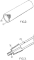
- Tubular members 15, 17 include, Fig. 2 , a first, outer tube 21, or sheath, and a second, inner tube 23.
- Outer tube 21 is made from an elastic material which is elastically extensible in an axial or longitudinal direction, but which need not be elastically extensible in a radial or transverse direction.
- the purpose of the longitudinal extensibility is to permit axial extension of tubular members 15, 17 to enable their placement over the head of the user, and subsequently to permit it to contract into closely fitting engagement with the user's head to hold the device to which it is applied on its proper position.
- a preferred material from which outer tube 21 can be formed is a woven cloth composed of flame resistant meta-aramid yarn such as NOMEX (trademark of Dupont Inc.) fiber.
- NOMEX has the advantage to have a good heat resistance compatible with aircraft regulation, a great mechanical resistance and particularly to defibering, and a homogeneous sliding between fibers which guarantee a homogeneous elongation of the tubular members.
- Inner tube 23 fits completely within outer tube 21 and is formed from a fluid impermeable and elastic material, preferably a silicone-type material. Typically, inner tube 23 is a silicone molded tube.
- the inner tube 23, being fluid impermeable and elastic, is used to transform the breathing gas pressure into a mechanical increase of the tubular members length and the outer tube 21 is used to protect the inner tube 23 from aggressive contact and to direct the force generated by the breathing gas pressure to the longitudinal extension of the tubular members.
- the tubular members 15, 17 are connected to the valve housing 11 by means of nozzles 30, Fig. 3 .
- the nozzle comprises a cylindrical cover 34 which gets wider in the direction of the tubular members to spread constraints generated by inflating the harness.
- the end of the inner tube 23 is fixed inside the cylindrical cover 34 and is thicker than the other part of the tube also to spread constraints.
- the breathing gas generated by OBOGS has a pressure as low as 0.7 bars and a maximum flow rate of around 85 l/min.
- the tube needs to elongate by a factor of around 1.5 to allow the user's head to position into the harness, whatever the head size is.
- the tube elongates by a factor or only 1.4 if the pressure delivered by OBOGS is only 0.5 bars.
- the harness needs to squeeze the head, when deflated, with strength of more than 20 Newton.
- the inner diameter of the tube needs to be around 18 mm.
- the man skilled in the art determines the requested silicone section which, with the inner diameter, gives the thickness.
- the silicone is chosen advantageously among those having a hardness of less than 75 shore A, preferably less than 35 shore A, and a Young's modulus of less than 200MPa.
- the number of spindles and the weaving angle are advantageously adjusted during the weaving of the outer tube to achieve a longitudinal stretch ratio of the outer tube alone of 3.
- the outer tube is considered by itself, without the inner tube and the comparison is done between the outer tube stretched longitudinally and the outer tube in a rest position which means it has a diameter of approximately 20 mm, i.e. the outer diameter of the inner tube.
Landscapes
- Health & Medical Sciences (AREA)
- Pulmonology (AREA)
- General Health & Medical Sciences (AREA)
- Business, Economics & Management (AREA)
- Emergency Management (AREA)
- Respiratory Apparatuses And Protective Means (AREA)
Description
- The invention relates to a breathing mask for aircraft comprising an inflatable head harness composed of elastic tubular devices.
- The respiratory mask typically worn by aircraft crewmembers must be attached surely and rapidly on the crewmember head. And it must be attached on an one-handed basis, since the user's other hand is frequently occupied in some other essential task.
- For example, if because of a pressurization failure, the pilot of an aircraft is required rapidly to don his respiratory mask to provide the necessary oxygen for breathing, he often must do so with one hand while his other hand is occupied in controlling the aircraft. Thus, the use of an inflatable head harness has been suggested in order to permit the respiratory mask to be donned using only one hand. The head harness is expanded diametrically by the introduction of pressurized gas to cause the harness to increase in size so that it can be positioned over the head of the user. The gas flow is controlled by a valve attached to the respiratory mask, and, after enlargement, the respiratory mask is placed in position over the nose and mouth, with the head harness extended over and spaced from the back of the head. Once the respiratory mask has been properly positioned, the pressure in the head harness is released, causing the harness to contract and to contact the head of the pilot, whereby the respiratory mask is securely held in its proper position. Meanwhile, the pilot's other hand is free to control the aircraft or to perform such other tasks as may be required.
- An inflatable head harness is shown and described in
U.S. Pat. No. 3,599,636 in which the harness is defined by a pair of spaced, expandable rubber tubes which are housed within an outer casing of material which has limited yieldability and which is initially in pleated form. - The disclosed harness needs to work a minimum pressure of 6 bars at the arrival of breathing gas.
- However, more and more often, the breathing gas supply system of aircraft uses Onboard Oxygen Generating System, or OBOGS, which delivers breathing gas at a maximum pressure of 4 to 5 bars. This pressure is not sufficient to inflate correctly the usual inflatable harness for allowing the crewmember to install the mask easily.
- Therefore, there is a need for an apparatus which allows the use of inflatable harness with the pressure level delivered by OBOGS.
- To better address one or more concerns, in a first aspect of the invention, a breathing mask for aircraft comprising an inflatable harness composed of elastic tubular devices, each elastic tubular device comprising:
- an inner tube made of an elastic and gas impermeable material; and,
- a sheath surrounding the inner tube and made of a woven cloth of flame resistant meta-aramid yarns, wherein
the tubular device has a longitudinal extension of at least approximately 1,4 when inflated by a gas having a pressure of approximately 0.5 bar. - The tubular devices have advantageously the same longitudinal extension ratio than a standard tubular device for inflatable harness but this extension ratio is achieved with a pressure level which can be obtained from OBOGS.
- In particular embodiments,
- the tubular device has a longitudinal extension of at least approximately 1.5 when inflated by a gas having a pressure of approximately 0.7 bar.
- the inner tube is molded in silicon material, said silicon having a hardness of less than 75 shore A, and Young's modulus of less than 200MPa.
- said silicon has a hardness of less than 35 shore A.
- internal diameter of the inner tube is at least approximately 17 millimeters.
- the sheath is woven so that its longitudinal stretch ratio is approximately 3.
- the tubular device is connected to a gas source through nozzles, said nozzles comprising a cylindrical cover which gets wider in the direction of the tubular device.
- the inner tube of said tubular device has at least one end portion and an extensible portion, the end portion is fixed inside a cylindrical cover, the extensible portion is directly connected to the end portion, and the end portion is thicker than the extensible portion of the inner tube.
- Depending on the type of the breathing mask and tubular device, a particular embodiment may be preferred as easier to adapt. Aspects of these particular embodiments may be combined or modified as appropriate or desired, however.
- These and other aspects of the invention will be apparent from and elucidated with reference to the embodiment described hereafter where:
-
Fig. 1 is an isometric view of a breathing mask with its inflatable harness according to an embodiment of the invention; -
Fig. 2 is an isometric view of a portion of a tube used in the harness of ofFig. 1 ; and -
Fig. 3 is a section view of a connection of the tube ofFig.2 with the breathing mask ofFig.1 . - In reference to
Fig. 1 , ahead harness 1 is utilized in conjunction with a respiratory mask 3 of the type intended to provide oxygen to aircraft crewmembers under high altitude conditions or under conditions in which the aircraft cabin pressurization has for some reason been lost. - Mask 3 includes a flexible, generally cup-shaped face member 5 adapted to fit over and cover the mouth and nose of the user, and which is suitably shaped to provide a comfortable fit.
- Positioned at the forward outer end of face member 3 is a control valve 6 having a slidable valve member 7, 9 positioned on each side of control valve 5, each of which is adapted to selectively open and close a passage way to admit a pressurized fluid to the harness structure, all will hereinafter be described. Control valve 6 can be a two-position valve, wherein in one position it permits communication between the head harness and the atmosphere while it simultaneously prevents the entry of pressurized gas to the harness structure. As it is apparent, control valve 6 is adapted for one-handed use, thereby permitting the other hand of the user to be occupied with other tasks. Although a specific structure of control valve is shown and described, it will be apparent to those skilled in the art that other types of control valve structure could be successfully utilized together with the head harness structure of the invention, and the control valve structure shown is for illustrative purposes only.
- Control valve 6 includes a
valve housing 11, which fits over and is secured toforward position 13 of face member 3, and to which is attached twotubular members Tubular members Space members 19 are positioned there between to holdtubular elements -
Tubular members Fig. 2 , a first, outer tube 21, or sheath, and a second,inner tube 23. Outer tube 21 is made from an elastic material which is elastically extensible in an axial or longitudinal direction, but which need not be elastically extensible in a radial or transverse direction. The purpose of the longitudinal extensibility is to permit axial extension oftubular members -
Inner tube 23 fits completely within outer tube 21 and is formed from a fluid impermeable and elastic material, preferably a silicone-type material. Typically,inner tube 23 is a silicone molded tube. - Therefore, the
inner tube 23, being fluid impermeable and elastic, is used to transform the breathing gas pressure into a mechanical increase of the tubular members length and the outer tube 21 is used to protect theinner tube 23 from aggressive contact and to direct the force generated by the breathing gas pressure to the longitudinal extension of the tubular members. - The
tubular members valve housing 11 by means ofnozzles 30,Fig. 3 . - The nozzle comprises a
cylindrical cover 34 which gets wider in the direction of the tubular members to spread constraints generated by inflating the harness. - The end of the
inner tube 23 is fixed inside thecylindrical cover 34 and is thicker than the other part of the tube also to spread constraints. - The breathing gas generated by OBOGS has a pressure as low as 0.7 bars and a maximum flow rate of around 85 l/min.
- The tube needs to elongate by a factor of around 1.5 to allow the user's head to position into the harness, whatever the head size is.
- However, it may be acceptable that the tube elongates by a factor or only 1.4 if the pressure delivered by OBOGS is only 0.5 bars.
- To offer a good comfort to the user while maintaining closely in place the breathing mask, the harness needs to squeeze the head, when deflated, with strength of more than 20 Newton.
- With a pressure of 0.7 bars and considering the silicone elasticity, it appears that the inner diameter of the tube needs to be around 18 mm.
- Knowing the silicone elasticity and the elongation ratio, the man skilled in the art determines the requested silicone section which, with the inner diameter, gives the thickness.
- In order to have a silicone thickness with a good protection against puncture, the silicone is chosen advantageously among those having a hardness of less than 75 shore A, preferably less than 35 shore A, and a Young's modulus of less than 200MPa.
- To obtain the correct longitudinal extensibility of 1.5, and to protect against a puncture due to an overpressure, for instance, of 9 bars, the number of spindles and the weaving angle are advantageously adjusted during the weaving of the outer tube to achieve a longitudinal stretch ratio of the outer tube alone of 3. To calculate the longitudinal stretch ratio, the outer tube is considered by itself, without the inner tube and the comparison is done between the outer tube stretched longitudinally and the outer tube in a rest position which means it has a diameter of approximately 20 mm, i.e. the outer diameter of the inner tube.
- Other variation to the disclosed embodiments can be understood and effected by those skilled in the art in practicing the claimed invention, from a study of the drawings, the disclosure and the appended claims. In the claims, the word "comprising does not exclude other elements, and the indefinite article "a" or "an" does not exclude a plurality.
Claims (10)
- A breathing mask for aircraft comprising an inflatable harness (1) composed of elastic tubular devices (15,17), each elastic tubular device comprising- an inner tube (23) made of an elastic and gas impermeable material; and,- a sheath (21) surrounding the inner tube and made of a woven cloth of yarns, characterized in that the yarns are flame resistant meta-aramid yarns, and the tubular device has a longitudinal extension of at least approximately 1,4 when inflated by a gas having a pressure of approximately 0.5 bar.
- The breathing mask according to claim 1, wherein the tubular devicehas a longitudinal extension of at least approximately 1.5 when inflated by a gas having a pressure of approximately 0.7 bar.
- The breathing mask according to claim 1 or 2, wherein the inner tube is molded in silicon material.
- The breathing mask according to claim 3, wherein said silicon has a hardness of less than 75 shore A, and Young's modulus of less than 200MPa.
- The breathing mask according to claim 4, wherein said silicon has a hardness of less than 35 shore A.
- The breathing mask according to any one of proceeding claims, wherein internal diameter of the inner tube is at least approximately 17 millimeters.
- The breathing mask according to any one of claims 1 to 6, wherein said sheath is woven so that its longitudinal stretch ratio is approximately 3.
- The breathing mask according to any one of claims 1 to 7, wherein said tubular device is connected to a gas source through nozzles, said nozzles comprising a cylindrical cover which gets wider in the direction of the tubular device.
- The breathing mask according to any one of claims 1 to 7, wherein the inner tube of said tubular device has at least one end portion and an extensible portion, the end portion is fixed inside a cylindrical cover, the extensible portion is directly connected to the end portion, and the end portion is thicker than the extensible portion of the inner tube.
- The breathing mask according to claim 9, wherein said end portion of the inner tube has an internal cross section smaller than an internal cross section of said extensible portion of the inner tube.
Applications Claiming Priority (1)
| Application Number | Priority Date | Filing Date | Title |
|---|---|---|---|
| PCT/IB2008/052205 WO2009115868A1 (en) | 2008-03-19 | 2008-03-19 | Elastic tubular device and inflatable head harness for aircraft breathing mask |
Publications (2)
| Publication Number | Publication Date |
|---|---|
| EP2265336A1 EP2265336A1 (en) | 2010-12-29 |
| EP2265336B1 true EP2265336B1 (en) | 2017-10-11 |
Family
ID=40084364
Family Applications (1)
| Application Number | Title | Priority Date | Filing Date |
|---|---|---|---|
| EP08763206.3A Active EP2265336B1 (en) | 2008-03-19 | 2008-03-19 | Elastic tubular device and inflatable head harness for aircraft breathing mask |
Country Status (6)
| Country | Link |
|---|---|
| US (1) | US9027557B2 (en) |
| EP (1) | EP2265336B1 (en) |
| CN (1) | CN102026687B (en) |
| BR (1) | BRPI0822344A2 (en) |
| CA (1) | CA2718635C (en) |
| WO (1) | WO2009115868A1 (en) |
Families Citing this family (12)
| Publication number | Priority date | Publication date | Assignee | Title |
|---|---|---|---|---|
| WO2012017265A1 (en) * | 2010-08-02 | 2012-02-09 | Intertechnique | Tube with protrusions for inflatable harness of breathing mask |
| WO2012066394A2 (en) * | 2010-11-15 | 2012-05-24 | Intertechnique | A respiratory equipment for aircraft with an inflatable harness |
| EP2773432B1 (en) * | 2011-10-31 | 2017-03-01 | Zodiac Aerotechnics | Method for storing a respiratory mask and respiratory equipment including a respiratory mask and a storage element |
| US8291942B2 (en) | 2011-11-04 | 2012-10-23 | Blue Gentian, Llc | Expandable hose assembly |
| US9545530B2 (en) | 2012-07-11 | 2017-01-17 | B/E Aerospace, Inc. | Aircraft crew member protective breathing apparatus |
| US9498656B2 (en) | 2012-07-11 | 2016-11-22 | B/E Aerospace, Inc. | Aircraft crew member protective breathing apparatus |
| DE102013206181B4 (en) | 2013-04-09 | 2016-12-01 | B/E Aerospace Systems Gmbh | Passenger oxygen mask and breathing bag for an oxygen mask |
| DE102013220478B4 (en) | 2013-10-10 | 2022-05-25 | B/E Aerospace Systems Gmbh | container with cover |
| EP3169390B1 (en) * | 2014-07-16 | 2019-11-27 | Breas Medical, Inc. | Facial interface and headgear system for use with ventilation and positive air pressure systems |
| US10974083B2 (en) * | 2015-02-06 | 2021-04-13 | B/E Aerospace, Inc. | Inflatable harness assembly for aircraft oxygen crew mask |
| US10537752B2 (en) * | 2015-06-29 | 2020-01-21 | B/E Aerospace, Inc. | Harness assembly for aircraft pilot crew mask |
| US20230226296A1 (en) * | 2022-01-20 | 2023-07-20 | ResMed Asia Pte. Ltd. | Stabilising structures for patient interfaces |
Citations (1)
| Publication number | Priority date | Publication date | Assignee | Title |
|---|---|---|---|---|
| US3599636A (en) * | 1969-12-12 | 1971-08-17 | Intertechnique Sa | Inflatable head harness for respirator devices |
Family Cites Families (15)
| Publication number | Priority date | Publication date | Assignee | Title |
|---|---|---|---|---|
| US3000530A (en) | 1959-08-08 | 1961-09-19 | Interconsult Ab | Transport tanks having a substantially spherical wall |
| US4437462A (en) | 1981-11-19 | 1984-03-20 | Figgie International Inc. | Pneumatic head harness |
| DE3608668A1 (en) | 1986-03-14 | 1987-09-17 | Biw Isolierstoffe Gmbh | Process for producing a diaphragm-like tube and tube produced according to the process |
| US4729765A (en) * | 1986-12-22 | 1988-03-08 | Eckels John F | Method of using meconium aspirator components |
| US5269296A (en) * | 1991-10-29 | 1993-12-14 | Landis Robert M | Nasal continuous positive airway pressure apparatus and method |
| EP0672430A3 (en) * | 1994-03-15 | 1995-12-27 | Fisher & Paykel | Humidification line. |
| FR2778575B1 (en) * | 1998-05-12 | 2000-07-28 | Intertechnique Sa | RESPIRATORY PROTECTION EQUIPMENT WITH FAST SETUP |
| US7802574B2 (en) * | 2000-01-18 | 2010-09-28 | Schultz Joseph P | Medical component system |
| US6523539B2 (en) * | 2001-07-02 | 2003-02-25 | Be Intellectual Property Inc. | Self-elongating oxygen hose for stowable aviation crew oxygen mask |
| CN2730427Y (en) * | 2004-08-10 | 2005-10-05 | 宋琇莹 | inflatable swim belt |
| CN101115521B (en) * | 2004-11-10 | 2011-05-25 | 雷斯梅德有限公司 | Apparatus for adjusting respiratory mask sealing force |
| US20070012317A1 (en) * | 2005-07-08 | 2007-01-18 | Flagler Robert W | Medical device tube |
| US8146597B2 (en) * | 2005-10-19 | 2012-04-03 | Resmed Limited | Nasal mask assembly |
| ES2592677T3 (en) * | 2006-07-28 | 2016-12-01 | Resmed Limited | Administration of respiratory therapy |
| US8100127B2 (en) * | 2007-11-29 | 2012-01-24 | Worley Brian D | Catheter guiding flexible connector |
-
2008
- 2008-03-19 EP EP08763206.3A patent/EP2265336B1/en active Active
- 2008-03-19 CN CN2008801292531A patent/CN102026687B/en active Active
- 2008-03-19 CA CA2718635A patent/CA2718635C/en active Active
- 2008-03-19 US US12/922,860 patent/US9027557B2/en active Active
- 2008-03-19 BR BRPI0822344-0A patent/BRPI0822344A2/en active IP Right Grant
- 2008-03-19 WO PCT/IB2008/052205 patent/WO2009115868A1/en not_active Ceased
Patent Citations (1)
| Publication number | Priority date | Publication date | Assignee | Title |
|---|---|---|---|---|
| US3599636A (en) * | 1969-12-12 | 1971-08-17 | Intertechnique Sa | Inflatable head harness for respirator devices |
Also Published As
| Publication number | Publication date |
|---|---|
| CN102026687A (en) | 2011-04-20 |
| BRPI0822344A2 (en) | 2015-06-16 |
| US9027557B2 (en) | 2015-05-12 |
| CA2718635C (en) | 2016-03-01 |
| WO2009115868A1 (en) | 2009-09-24 |
| EP2265336A1 (en) | 2010-12-29 |
| US20110011405A1 (en) | 2011-01-20 |
| CA2718635A1 (en) | 2009-09-24 |
| CN102026687B (en) | 2012-11-07 |
Similar Documents
| Publication | Publication Date | Title |
|---|---|---|
| US9027557B2 (en) | Elastic tubular device and inflatable head harness for aircraft breathing mask | |
| US20130037031A1 (en) | Tube with protrusions for inflatable harness of breathing mask | |
| EP2640474B1 (en) | A respiratory equipment for aircraft with an inflatable harness | |
| US4437462A (en) | Pneumatic head harness | |
| EP2773432B1 (en) | Method for storing a respiratory mask and respiratory equipment including a respiratory mask and a storage element | |
| EP3253458B1 (en) | Inflatable harness assembly for aircraft oxygen crew mask | |
| EP3313535B1 (en) | Harness assembly for aircraft pilot crew mask | |
| BRPI0822344B1 (en) | "AIRCRAFT BREATH MASK" |
Legal Events
| Date | Code | Title | Description |
|---|---|---|---|
| PUAI | Public reference made under article 153(3) epc to a published international application that has entered the european phase |
Free format text: ORIGINAL CODE: 0009012 |
|
| 17P | Request for examination filed |
Effective date: 20100928 |
|
| AK | Designated contracting states |
Kind code of ref document: A1 Designated state(s): AT BE BG CH CY CZ DE DK EE ES FI FR GB GR HR HU IE IS IT LI LT LU LV MC MT NL NO PL PT RO SE SI SK TR |
|
| AX | Request for extension of the european patent |
Extension state: AL BA MK RS |
|
| RIN1 | Information on inventor provided before grant (corrected) |
Inventor name: DUSSART, LAURENT Inventor name: GRETER, VINCENT Inventor name: SCHOETTEL, REMY |
|
| DAX | Request for extension of the european patent (deleted) | ||
| RAP1 | Party data changed (applicant data changed or rights of an application transferred) |
Owner name: ZODIAC AEROTECHNICS |
|
| 17Q | First examination report despatched |
Effective date: 20140403 |
|
| GRAP | Despatch of communication of intention to grant a patent |
Free format text: ORIGINAL CODE: EPIDOSNIGR1 |
|
| STAA | Information on the status of an ep patent application or granted ep patent |
Free format text: STATUS: GRANT OF PATENT IS INTENDED |
|
| INTG | Intention to grant announced |
Effective date: 20170707 |
|
| RIN1 | Information on inventor provided before grant (corrected) |
Inventor name: GRETER, VINCENT Inventor name: DUSSART, LAURENT Inventor name: SCHOETTEL, REMY |
|
| GRAS | Grant fee paid |
Free format text: ORIGINAL CODE: EPIDOSNIGR3 |
|
| GRAA | (expected) grant |
Free format text: ORIGINAL CODE: 0009210 |
|
| STAA | Information on the status of an ep patent application or granted ep patent |
Free format text: STATUS: THE PATENT HAS BEEN GRANTED |
|
| AK | Designated contracting states |
Kind code of ref document: B1 Designated state(s): AT BE BG CH CY CZ DE DK EE ES FI FR GB GR HR HU IE IS IT LI LT LU LV MC MT NL NO PL PT RO SE SI SK TR |
|
| REG | Reference to a national code |
Ref country code: GB Ref legal event code: FG4D |
|
| REG | Reference to a national code |
Ref country code: CH Ref legal event code: EP |
|
| REG | Reference to a national code |
Ref country code: IE Ref legal event code: FG4D |
|
| REG | Reference to a national code |
Ref country code: AT Ref legal event code: REF Ref document number: 935518 Country of ref document: AT Kind code of ref document: T Effective date: 20171115 |
|
| REG | Reference to a national code |
Ref country code: DE Ref legal event code: R096 Ref document number: 602008052461 Country of ref document: DE |
|
| REG | Reference to a national code |
Ref country code: NL Ref legal event code: MP Effective date: 20171011 |
|
| REG | Reference to a national code |
Ref country code: LT Ref legal event code: MG4D Ref country code: FR Ref legal event code: PLFP Year of fee payment: 11 |
|
| REG | Reference to a national code |
Ref country code: AT Ref legal event code: MK05 Ref document number: 935518 Country of ref document: AT Kind code of ref document: T Effective date: 20171011 |
|
| PG25 | Lapsed in a contracting state [announced via postgrant information from national office to epo] |
Ref country code: NL Free format text: LAPSE BECAUSE OF FAILURE TO SUBMIT A TRANSLATION OF THE DESCRIPTION OR TO PAY THE FEE WITHIN THE PRESCRIBED TIME-LIMIT Effective date: 20171011 |
|
| PG25 | Lapsed in a contracting state [announced via postgrant information from national office to epo] |
Ref country code: SE Free format text: LAPSE BECAUSE OF FAILURE TO SUBMIT A TRANSLATION OF THE DESCRIPTION OR TO PAY THE FEE WITHIN THE PRESCRIBED TIME-LIMIT Effective date: 20171011 Ref country code: ES Free format text: LAPSE BECAUSE OF FAILURE TO SUBMIT A TRANSLATION OF THE DESCRIPTION OR TO PAY THE FEE WITHIN THE PRESCRIBED TIME-LIMIT Effective date: 20171011 Ref country code: LT Free format text: LAPSE BECAUSE OF FAILURE TO SUBMIT A TRANSLATION OF THE DESCRIPTION OR TO PAY THE FEE WITHIN THE PRESCRIBED TIME-LIMIT Effective date: 20171011 Ref country code: FI Free format text: LAPSE BECAUSE OF FAILURE TO SUBMIT A TRANSLATION OF THE DESCRIPTION OR TO PAY THE FEE WITHIN THE PRESCRIBED TIME-LIMIT Effective date: 20171011 Ref country code: NO Free format text: LAPSE BECAUSE OF FAILURE TO SUBMIT A TRANSLATION OF THE DESCRIPTION OR TO PAY THE FEE WITHIN THE PRESCRIBED TIME-LIMIT Effective date: 20180111 |
|
| PG25 | Lapsed in a contracting state [announced via postgrant information from national office to epo] |
Ref country code: GR Free format text: LAPSE BECAUSE OF FAILURE TO SUBMIT A TRANSLATION OF THE DESCRIPTION OR TO PAY THE FEE WITHIN THE PRESCRIBED TIME-LIMIT Effective date: 20180112 Ref country code: IS Free format text: LAPSE BECAUSE OF FAILURE TO SUBMIT A TRANSLATION OF THE DESCRIPTION OR TO PAY THE FEE WITHIN THE PRESCRIBED TIME-LIMIT Effective date: 20180211 Ref country code: LV Free format text: LAPSE BECAUSE OF FAILURE TO SUBMIT A TRANSLATION OF THE DESCRIPTION OR TO PAY THE FEE WITHIN THE PRESCRIBED TIME-LIMIT Effective date: 20171011 Ref country code: HR Free format text: LAPSE BECAUSE OF FAILURE TO SUBMIT A TRANSLATION OF THE DESCRIPTION OR TO PAY THE FEE WITHIN THE PRESCRIBED TIME-LIMIT Effective date: 20171011 Ref country code: BG Free format text: LAPSE BECAUSE OF FAILURE TO SUBMIT A TRANSLATION OF THE DESCRIPTION OR TO PAY THE FEE WITHIN THE PRESCRIBED TIME-LIMIT Effective date: 20180111 Ref country code: AT Free format text: LAPSE BECAUSE OF FAILURE TO SUBMIT A TRANSLATION OF THE DESCRIPTION OR TO PAY THE FEE WITHIN THE PRESCRIBED TIME-LIMIT Effective date: 20171011 |
|
| REG | Reference to a national code |
Ref country code: DE Ref legal event code: R097 Ref document number: 602008052461 Country of ref document: DE |
|
| PG25 | Lapsed in a contracting state [announced via postgrant information from national office to epo] |
Ref country code: CZ Free format text: LAPSE BECAUSE OF FAILURE TO SUBMIT A TRANSLATION OF THE DESCRIPTION OR TO PAY THE FEE WITHIN THE PRESCRIBED TIME-LIMIT Effective date: 20171011 Ref country code: SK Free format text: LAPSE BECAUSE OF FAILURE TO SUBMIT A TRANSLATION OF THE DESCRIPTION OR TO PAY THE FEE WITHIN THE PRESCRIBED TIME-LIMIT Effective date: 20171011 Ref country code: EE Free format text: LAPSE BECAUSE OF FAILURE TO SUBMIT A TRANSLATION OF THE DESCRIPTION OR TO PAY THE FEE WITHIN THE PRESCRIBED TIME-LIMIT Effective date: 20171011 Ref country code: DK Free format text: LAPSE BECAUSE OF FAILURE TO SUBMIT A TRANSLATION OF THE DESCRIPTION OR TO PAY THE FEE WITHIN THE PRESCRIBED TIME-LIMIT Effective date: 20171011 |
|
| PLBE | No opposition filed within time limit |
Free format text: ORIGINAL CODE: 0009261 |
|
| STAA | Information on the status of an ep patent application or granted ep patent |
Free format text: STATUS: NO OPPOSITION FILED WITHIN TIME LIMIT |
|
| PG25 | Lapsed in a contracting state [announced via postgrant information from national office to epo] |
Ref country code: RO Free format text: LAPSE BECAUSE OF FAILURE TO SUBMIT A TRANSLATION OF THE DESCRIPTION OR TO PAY THE FEE WITHIN THE PRESCRIBED TIME-LIMIT Effective date: 20171011 Ref country code: IT Free format text: LAPSE BECAUSE OF FAILURE TO SUBMIT A TRANSLATION OF THE DESCRIPTION OR TO PAY THE FEE WITHIN THE PRESCRIBED TIME-LIMIT Effective date: 20171011 Ref country code: PL Free format text: LAPSE BECAUSE OF FAILURE TO SUBMIT A TRANSLATION OF THE DESCRIPTION OR TO PAY THE FEE WITHIN THE PRESCRIBED TIME-LIMIT Effective date: 20171011 |
|
| 26N | No opposition filed |
Effective date: 20180712 |
|
| REG | Reference to a national code |
Ref country code: CH Ref legal event code: PL |
|
| GBPC | Gb: european patent ceased through non-payment of renewal fee |
Effective date: 20180319 |
|
| PG25 | Lapsed in a contracting state [announced via postgrant information from national office to epo] |
Ref country code: MC Free format text: LAPSE BECAUSE OF FAILURE TO SUBMIT A TRANSLATION OF THE DESCRIPTION OR TO PAY THE FEE WITHIN THE PRESCRIBED TIME-LIMIT Effective date: 20171011 Ref country code: SI Free format text: LAPSE BECAUSE OF FAILURE TO SUBMIT A TRANSLATION OF THE DESCRIPTION OR TO PAY THE FEE WITHIN THE PRESCRIBED TIME-LIMIT Effective date: 20171011 |
|
| REG | Reference to a national code |
Ref country code: BE Ref legal event code: MM Effective date: 20180331 |
|
| REG | Reference to a national code |
Ref country code: IE Ref legal event code: MM4A |
|
| PG25 | Lapsed in a contracting state [announced via postgrant information from national office to epo] |
Ref country code: LU Free format text: LAPSE BECAUSE OF NON-PAYMENT OF DUE FEES Effective date: 20180319 |
|
| PG25 | Lapsed in a contracting state [announced via postgrant information from national office to epo] |
Ref country code: IE Free format text: LAPSE BECAUSE OF NON-PAYMENT OF DUE FEES Effective date: 20180319 |
|
| PG25 | Lapsed in a contracting state [announced via postgrant information from national office to epo] |
Ref country code: BE Free format text: LAPSE BECAUSE OF NON-PAYMENT OF DUE FEES Effective date: 20180331 Ref country code: GB Free format text: LAPSE BECAUSE OF NON-PAYMENT OF DUE FEES Effective date: 20180319 Ref country code: CH Free format text: LAPSE BECAUSE OF NON-PAYMENT OF DUE FEES Effective date: 20180331 Ref country code: LI Free format text: LAPSE BECAUSE OF NON-PAYMENT OF DUE FEES Effective date: 20180331 |
|
| PG25 | Lapsed in a contracting state [announced via postgrant information from national office to epo] |
Ref country code: MT Free format text: LAPSE BECAUSE OF NON-PAYMENT OF DUE FEES Effective date: 20180319 |
|
| PG25 | Lapsed in a contracting state [announced via postgrant information from national office to epo] |
Ref country code: TR Free format text: LAPSE BECAUSE OF FAILURE TO SUBMIT A TRANSLATION OF THE DESCRIPTION OR TO PAY THE FEE WITHIN THE PRESCRIBED TIME-LIMIT Effective date: 20171011 |
|
| PG25 | Lapsed in a contracting state [announced via postgrant information from national office to epo] |
Ref country code: PT Free format text: LAPSE BECAUSE OF FAILURE TO SUBMIT A TRANSLATION OF THE DESCRIPTION OR TO PAY THE FEE WITHIN THE PRESCRIBED TIME-LIMIT Effective date: 20171011 Ref country code: HU Free format text: LAPSE BECAUSE OF FAILURE TO SUBMIT A TRANSLATION OF THE DESCRIPTION OR TO PAY THE FEE WITHIN THE PRESCRIBED TIME-LIMIT; INVALID AB INITIO Effective date: 20080319 |
|
| PG25 | Lapsed in a contracting state [announced via postgrant information from national office to epo] |
Ref country code: CY Free format text: LAPSE BECAUSE OF FAILURE TO SUBMIT A TRANSLATION OF THE DESCRIPTION OR TO PAY THE FEE WITHIN THE PRESCRIBED TIME-LIMIT Effective date: 20171011 |
|
| REG | Reference to a national code |
Ref country code: DE Ref legal event code: R081 Ref document number: 602008052461 Country of ref document: DE Owner name: SAFRAN AEROSYSTEMS, FR Free format text: FORMER OWNER: ZODIAC AEROTECHNICS, PLAISIR, FR Ref country code: DE Ref legal event code: R081 Ref document number: 602008052461 Country of ref document: DE Owner name: SAFRAN AEROTECHNICS S.A.S., FR Free format text: FORMER OWNER: ZODIAC AEROTECHNICS, PLAISIR, FR |
|
| REG | Reference to a national code |
Ref country code: DE Ref legal event code: R081 Ref document number: 602008052461 Country of ref document: DE Owner name: SAFRAN AEROSYSTEMS, FR Free format text: FORMER OWNER: SAFRAN AEROTECHNICS S.A.S., PLAISIR, FR |
|
| PGFP | Annual fee paid to national office [announced via postgrant information from national office to epo] |
Ref country code: DE Payment date: 20260320 Year of fee payment: 19 |
|
| PGFP | Annual fee paid to national office [announced via postgrant information from national office to epo] |
Ref country code: FR Payment date: 20260324 Year of fee payment: 19 |