EP2264986A1 - Electronic device and sliding mechanism thereof - Google Patents
Electronic device and sliding mechanism thereof Download PDFInfo
- Publication number
- EP2264986A1 EP2264986A1 EP09178347A EP09178347A EP2264986A1 EP 2264986 A1 EP2264986 A1 EP 2264986A1 EP 09178347 A EP09178347 A EP 09178347A EP 09178347 A EP09178347 A EP 09178347A EP 2264986 A1 EP2264986 A1 EP 2264986A1
- Authority
- EP
- European Patent Office
- Prior art keywords
- slider
- electronic device
- fpc
- sliding mechanism
- wire
- Prior art date
- Legal status (The legal status is an assumption and is not a legal conclusion. Google has not performed a legal analysis and makes no representation as to the accuracy of the status listed.)
- Granted
Links
- 238000005452 bending Methods 0.000 claims description 4
- 230000004048 modification Effects 0.000 description 2
- 238000012986 modification Methods 0.000 description 2
- 230000002411 adverse Effects 0.000 description 1
- 238000010586 diagram Methods 0.000 description 1
Images



Classifications
-
- H—ELECTRICITY
- H04—ELECTRIC COMMUNICATION TECHNIQUE
- H04M—TELEPHONIC COMMUNICATION
- H04M1/00—Substation equipment, e.g. for use by subscribers
- H04M1/02—Constructional features of telephone sets
- H04M1/0202—Portable telephone sets, e.g. cordless phones, mobile phones or bar type handsets
- H04M1/026—Details of the structure or mounting of specific components
- H04M1/0274—Details of the structure or mounting of specific components for an electrical connector module
-
- H—ELECTRICITY
- H04—ELECTRIC COMMUNICATION TECHNIQUE
- H04M—TELEPHONIC COMMUNICATION
- H04M1/00—Substation equipment, e.g. for use by subscribers
- H04M1/02—Constructional features of telephone sets
- H04M1/0202—Portable telephone sets, e.g. cordless phones, mobile phones or bar type handsets
- H04M1/0206—Portable telephones comprising a plurality of mechanically joined movable body parts, e.g. hinged housings
- H04M1/0208—Portable telephones comprising a plurality of mechanically joined movable body parts, e.g. hinged housings characterized by the relative motions of the body parts
- H04M1/0235—Slidable or telescopic telephones, i.e. with a relative translation movement of the body parts; Telephones using a combination of translation and other relative motions of the body parts
- H04M1/0237—Sliding mechanism with one degree of freedom
Definitions
- the application relates in general to an electronic device and in particular to an electronic device having a sliding mechanism.
- a conventional sliding-type mobile phone includes a first body 100 and a second body 200 reciprocally movable with respect to each other (as the arrows indicate in FIG. 1 ), wherein the first body 100 includes a keypad 300, and the second body 200 includes a screen 400.
- the first body 100 and the second body 200 are electrically connected by a flexible printed circuit board (not shown).
- a flexible printed circuit board (not shown).
- buckling deformation and damage of the flexible printed circuit board may occur, thus adversely leading to failure of mobile phone functions.
- the application provides a sliding mechanism including a first member, a second member, a slider, a wire, and a flexible printed circuit (FPC).
- the first member and the slider are movable with respect to the second member.
- the wire connects the first member with the slider.
- the FPC is extended through a first opening of the slider and a second opening of the second member. When the first member slides with respect to the second member along a first direction, the slider and the FPC are dragged by the wire along a second direction opposite to the first direction.
- FIG. 1 is a perspective diagram of a conventional sliding-type mobile phone
- FIG. 2A is a sliding mechanism when in an open state in accordance with an embodiment of the invention.
- FIG. 2B is a sectional view along X1-X2 in FIG. 2A ;
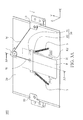
- FIG. 3A is a sliding mechanism when in a closed state in accordance with an embodiment of the invention.
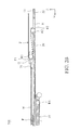
- FIG. 3B is a sectional view along X3-X4 in FIG. 3A .
- FIG. 2A depicts an embodiment of a sliding mechanism 500 when in an open state
- FIG. 3A depicts the sliding mechanism 500 when in a closed state
- the sliding mechanism 500 of FIGs. 2A and 3A can be disposed in an electronic device for connecting the first body 100 to the second body 200 as shown in FIG. 1 , so as to prevent buckling deformation and damage of a flexible printed circuit F.
- the electronic device may be a mobile phone, PDA, Ultra-Mobile PC (UMPC), or tablet PC.
- UMPC Ultra-Mobile PC
- the sliding mechanism 500 is in the open state ( FIG. 2A )
- the first body 100 and the second body 200 overlap only in a small area thereof, such as shown in FIG. 1
- the sliding mechanism 500 is switched to the closed state ( FIG. 3A )
- the first body 100 and the second body 200 overlap completely.
- the sliding mechanism 500 includes a first member 10, a second member 20, a slider 30, a wire W, at least one elastic element S, and a flexible printed circuit F.
- the first member 10 is fixed to the first body 100
- the second member is fixed to the second body 200.
- the first member 10 moves with respect to the second member 20 along the Y axis.
- both ends of the wire W are respectively bonded to the first member 10 and the slider 30, and a pulley P is disposed on the second member 20 with the wire W extended therethrough.
- a pulley P is disposed on the second member 20 with the wire W extended therethrough.
- the slider 30 is disposed on a first side 21 of the second member 20, and the first member 10 is disposed on a second side 22 of the second member 20, opposite to the first side 21.
- a first opening G is formed between a main body 31 and a first rod R1 of the slider 31.
- the flexible circuit board F is extended from the first side 21 of second member 20, through the first opening G and a second opening H of the second member 20, to the second side 22 for electrical connection between the first body 100 and the second body 200.
- a first bending portion F1 and a second bending portion F2 of the flexible circuit board F are respectively formed on the first rod R1 of the slider 30 and a second rod R2 of the second member 20, such that the flexible circuit board F has an S-shaped cross-section.
- the first member 10 when the sliding mechanism 500 is in the open state, the first member 10 is in a first position with respect to the second member 20.
- the elastic element S can provide an elastic force to the slide 30 so that the wire W is tensioned, thus forming the S-shaped cross-section of the flexible circuit board F, as shown in FIG. 2B .
- the sliding mechanism 500 switches from the open state to the closed state, the first member 10 slides with respect to the second member 20 along the -Y direction (first direction) from the first position to a second position.
- the wire W is further tensioned, and the slider 30 is dragged by the wire W along the Y direction (second direction).
- the flexible circuit board F is impelled by the first rod R1 along the Y direction, thus preventing buckling and damage thereof when the first member 10 slides along the -Y direction.
- the elastic element S can provide an elastic force to move the slider 30 along the -Y direction, such that the flexible circuit board F returns to the state as shown in FIGs. 2A and 2B .
- the sliding mechanism 500 further comprises a third rod R3 disposed on the first member 10, as shown in FIGs. 2B and 3B .
- the sliding mechanism 500 may comprise a plurality of elastic elements S, such as two extension springs respectively disposed on opposite sides of the slider 30 to facilitate sliding stability.
- the application provides a sliding mechanism connecting a first body and a second body of an electronic device, wherein the first body and the second body are electrically connected by a flexible circuit board.
- the sliding mechanism can prevent buckling deformation and damage of the flexible printed circuit during reciprocal sliding of the first body and the second body, so as to extend life of usage.
Landscapes
- Engineering & Computer Science (AREA)
- Signal Processing (AREA)
- Telephone Set Structure (AREA)
Abstract
Description
- This Application claims priority of Taiwan Patent Application No.
098120380, filed on June 18, 2009 - The application relates in general to an electronic device and in particular to an electronic device having a sliding mechanism.
- Referring to
FIG. 1 , a conventional sliding-type mobile phone includes afirst body 100 and asecond body 200 reciprocally movable with respect to each other (as the arrows indicate inFIG. 1 ), wherein thefirst body 100 includes akeypad 300, and thesecond body 200 includes ascreen 400. - The
first body 100 and thesecond body 200 are electrically connected by a flexible printed circuit board (not shown). However, when sliding between thefirst body 100 and thesecond body 200, buckling deformation and damage of the flexible printed circuit board may occur, thus adversely leading to failure of mobile phone functions. - The application provides a sliding mechanism including a first member, a second member, a slider, a wire, and a flexible printed circuit (FPC). The first member and the slider are movable with respect to the second member. The wire connects the first member with the slider. The FPC is extended through a first opening of the slider and a second opening of the second member. When the first member slides with respect to the second member along a first direction, the slider and the FPC are dragged by the wire along a second direction opposite to the first direction.
- The invention can be more fully understood by reading the subsequent detailed description and examples with references made to the accompanying drawings, wherein:
-
FIG. 1 is a perspective diagram of a conventional sliding-type mobile phone ; -
FIG. 2A is a sliding mechanism when in an open state in accordance with an embodiment of the invention; -
FIG. 2B is a sectional view along X1-X2 inFIG. 2A ; -
FIG. 3A is a sliding mechanism when in a closed state in accordance with an embodiment of the invention; and -
FIG. 3B is a sectional view along X3-X4 inFIG. 3A . -
FIG. 2A depicts an embodiment of asliding mechanism 500 when in an open state, andFIG. 3A depicts thesliding mechanism 500 when in a closed state. Thesliding mechanism 500 ofFIGs. 2A and3A can be disposed in an electronic device for connecting thefirst body 100 to thesecond body 200 as shown inFIG. 1 , so as to prevent buckling deformation and damage of a flexible printed circuit F. In this embodiment, the electronic device may be a mobile phone, PDA, Ultra-Mobile PC (UMPC), or tablet PC. When thesliding mechanism 500 is in the open state (FIG. 2A ), thefirst body 100 and thesecond body 200 overlap only in a small area thereof, such as shown inFIG. 1 . When thesliding mechanism 500 is switched to the closed state (FIG. 3A ), thefirst body 100 and thesecond body 200 overlap completely. - Referring to
FIG. 2A , thesliding mechanism 500 includes afirst member 10, asecond member 20, aslider 30, a wire W, at least one elastic element S, and a flexible printed circuit F. In this embodiment, thefirst member 10 is fixed to thefirst body 100, and the second member is fixed to thesecond body 200. When thefirst body 100 slides with respect to thesecond body 200, thefirst member 10 moves with respect to thesecond member 20 along the Y axis. - In
FIG. 2A , both ends of the wire W are respectively bonded to thefirst member 10 and theslider 30, and a pulley P is disposed on thesecond member 20 with the wire W extended therethrough. As the arrows shown inFIG. 3A , when thefirst member 10 slides with respect to thesecond member 20 along the -Y direction, the wire W is pulled by thefirst member 10 and moved around the pulley P. - As depicted in
FIGs. 2B and3B , theslider 30 is disposed on afirst side 21 of thesecond member 20, and thefirst member 10 is disposed on asecond side 22 of thesecond member 20, opposite to thefirst side 21. In this embodiment, a first opening G is formed between amain body 31 and a first rod R1 of theslider 31. The flexible circuit board F is extended from thefirst side 21 ofsecond member 20, through the first opening G and a second opening H of thesecond member 20, to thesecond side 22 for electrical connection between thefirst body 100 and thesecond body 200. Here, a first bending portion F1 and a second bending portion F2 of the flexible circuit board F are respectively formed on the first rod R1 of theslider 30 and a second rod R2 of thesecond member 20, such that the flexible circuit board F has an S-shaped cross-section. - Referring in
FIGs. 2A and2B , when thesliding mechanism 500 is in the open state, thefirst member 10 is in a first position with respect to thesecond member 20. The elastic element S can provide an elastic force to theslide 30 so that the wire W is tensioned, thus forming the S-shaped cross-section of the flexible circuit board F, as shown inFIG. 2B . - Referring in
FIGs. 3A and3B , when thesliding mechanism 500 switches from the open state to the closed state, thefirst member 10 slides with respect to thesecond member 20 along the -Y direction (first direction) from the first position to a second position. During sliding of thefirst member 10 along the -Y direction, the wire W is further tensioned, and theslider 30 is dragged by the wire W along the Y direction (second direction). Specifically, the flexible circuit board F is impelled by the first rod R1 along the Y direction, thus preventing buckling and damage thereof when thefirst member 10 slides along the -Y direction. - To return the
first member 10 from the second position to the first position, the elastic element S can provide an elastic force to move theslider 30 along the -Y direction, such that the flexible circuit board F returns to the state as shown inFIGs. 2A and2B . In this embodiment, thesliding mechanism 500 further comprises a third rod R3 disposed on thefirst member 10, as shown inFIGs. 2B and3B . When thefirst member 10 moves with respect to thesecond member 20, the flexible circuit board F slides through the third rod R3. In some embodiments, thesliding mechanism 500 may comprise a plurality of elastic elements S, such as two extension springs respectively disposed on opposite sides of theslider 30 to facilitate sliding stability. - The application provides a sliding mechanism connecting a first body and a second body of an electronic device, wherein the first body and the second body are electrically connected by a flexible circuit board. The sliding mechanism can prevent buckling deformation and damage of the flexible printed circuit during reciprocal sliding of the first body and the second body, so as to extend life of usage.
- While the invention has been described by way of example and in terms of preferred embodiment, it is to be understood that the invention is not limited thereto. To the contrary, it is intended to cover various modifications and similar arrangements (as would be apparent to those skilled in the art). Therefore, the scope of the appended claims should be accorded the broadest interpretation to encompass all such modifications and similar arrangements.
Claims (9)
- An electronic device, comprising:a first body (100);a second body (200);a sliding mechanism (500), comprising:a first member (10) fixed to the first body;a second member (20) fixed to the second body, wherein the first member is movable with respect to the second member, and the second member comprises a second opening (11);a slider (30), being movable with respect to the second member and comprising a first opening (G);a wire (W), connecting the first member with the slider; anda flexible printed circuit (FPC), extended through the first opening (G) of the slider and the second opening (H) of the second member,
wherein when the first member slides with respect to the second member along a first direction (-Y), the slider and the FPC are dragged by the wire along a second direction (Y) opposite to the first direction. - The electronic device as claimed in claim 1, wherein the sliding mechanism further comprises an elastic element (S) connecting the slider with the second member so that the wire is tensioned.
- The electronic device as claimed in claim 2, wherein the elastic element is a tension spring.
- The electronic device as claimed in any of the preceding claims, wherein the sliding mechanism further comprises a pulley (P) disposed on the second member (20), and the wire is extended from the slider (30) through the pulley to the first member.
- The electronic device as claimed in any of the preceding claims, wherein the slider and the first member are respectively disposed on a first side (21) and a second side (22) of the second member (20), and the FPC is extended from the first side through the first and second openings to the second side.
- The electronic device as claimed in any of the preceding claims, wherein the slider further comprises a main body and a first rod (R1) with the first opening formed therebetween, and the FPC forms a first bending portion on the first rod.
- The electronic device as claimed in any of the preceding claims, wherein the second member further comprises a second rod (R2), and the FPC forms a second bending portion on the second rod.
- The electronic device as claimed in any of the preceding claims, wherein the FPC has an S-shaped cross-section.
- The electronic device as claimed in any of the preceding claims, wherein the first member comprises a third rod (R3), and when the first member moves with respect to the second member, the FPC slides on the third rod.
Applications Claiming Priority (1)
| Application Number | Priority Date | Filing Date | Title |
|---|---|---|---|
| TW098120380A TWI386151B (en) | 2009-06-18 | 2009-06-18 | Electronic device and sliding mechanism thereof |
Publications (2)
| Publication Number | Publication Date |
|---|---|
| EP2264986A1 true EP2264986A1 (en) | 2010-12-22 |
| EP2264986B1 EP2264986B1 (en) | 2012-05-30 |
Family
ID=42782304
Family Applications (1)
| Application Number | Title | Priority Date | Filing Date |
|---|---|---|---|
| EP09178347A Not-in-force EP2264986B1 (en) | 2009-06-18 | 2009-12-08 | Electronic device and sliding mechanism thereof |
Country Status (3)
| Country | Link |
|---|---|
| US (1) | US8116835B2 (en) |
| EP (1) | EP2264986B1 (en) |
| TW (1) | TWI386151B (en) |
Families Citing this family (6)
| Publication number | Priority date | Publication date | Assignee | Title |
|---|---|---|---|---|
| US8113523B2 (en) * | 2009-10-14 | 2012-02-14 | Wonderland Nurserygoods Company Limited | Backrest reclining mechanism and related stroller |
| KR101789329B1 (en) * | 2011-02-07 | 2017-10-23 | 삼성전자주식회사 | Slide type portable terminal |
| US8850912B2 (en) * | 2012-04-13 | 2014-10-07 | First Dome Corporation | Linkage-type synchronous slide structure of relative slide assembly |
| TW201352115A (en) * | 2012-06-06 | 2013-12-16 | Chi Mei Comm Systems Inc | Routing cable mechanism and portable electronic device |
| TWI574479B (en) * | 2015-11-23 | 2017-03-11 | 緯創資通股份有限公司 | Telescopic device having carrier member, carrier member and cable thereof |
| TWI775036B (en) | 2020-01-14 | 2022-08-21 | 宏碁股份有限公司 | Heat dissipation fan |
Citations (3)
| Publication number | Priority date | Publication date | Assignee | Title |
|---|---|---|---|---|
| US20080298025A1 (en) | 2007-06-01 | 2008-12-04 | Chi Mei Communication Systems, Inc. | Sliding cover mechanism of portable electronic device |
| WO2009041610A1 (en) | 2007-09-28 | 2009-04-02 | Kyocera Corporation | Slide type mobile electronic device |
| US20090147451A1 (en) | 2007-12-06 | 2009-06-11 | Chih-Shan Yeh | Electronic device and sliding mechanism thereof |
Family Cites Families (7)
| Publication number | Priority date | Publication date | Assignee | Title |
|---|---|---|---|---|
| JP2003179678A (en) * | 2001-10-03 | 2003-06-27 | Nec Corp | Portable telephone |
| JP3656742B2 (en) | 2001-10-30 | 2005-06-08 | 日本電気株式会社 | Portable information terminal |
| WO2005020452A1 (en) * | 2003-08-25 | 2005-03-03 | M2Sys Co., Ltd | A sliding opening and closing device and a portable terminal having the same |
| EP1745555B1 (en) * | 2004-09-15 | 2008-12-17 | M2SYS Co., Ltd. | A sliding mechanism for opening and closing of cellular phone |
| JP4344887B2 (en) | 2004-10-13 | 2009-10-14 | 株式会社カシオ日立モバイルコミュニケーションズ | Portable information terminal |
| TWI330062B (en) * | 2007-12-07 | 2010-09-01 | Htc Corp | Handheld electronic device |
| CN101472430B (en) * | 2007-12-24 | 2011-12-14 | 鸿富锦精密工业(深圳)有限公司 | Sliding mechanism |
-
2009
- 2009-06-18 TW TW098120380A patent/TWI386151B/en not_active IP Right Cessation
- 2009-12-08 EP EP09178347A patent/EP2264986B1/en not_active Not-in-force
- 2009-12-09 US US12/633,846 patent/US8116835B2/en not_active Expired - Fee Related
Patent Citations (4)
| Publication number | Priority date | Publication date | Assignee | Title |
|---|---|---|---|---|
| US20080298025A1 (en) | 2007-06-01 | 2008-12-04 | Chi Mei Communication Systems, Inc. | Sliding cover mechanism of portable electronic device |
| WO2009041610A1 (en) | 2007-09-28 | 2009-04-02 | Kyocera Corporation | Slide type mobile electronic device |
| US20100195296A1 (en) * | 2007-09-28 | 2010-08-05 | Kyocera Corporation | Sliding portable electronic device |
| US20090147451A1 (en) | 2007-12-06 | 2009-06-11 | Chih-Shan Yeh | Electronic device and sliding mechanism thereof |
Also Published As
| Publication number | Publication date |
|---|---|
| TWI386151B (en) | 2013-02-11 |
| TW201101976A (en) | 2011-01-01 |
| EP2264986B1 (en) | 2012-05-30 |
| US8116835B2 (en) | 2012-02-14 |
| US20100323769A1 (en) | 2010-12-23 |
Similar Documents
| Publication | Publication Date | Title |
|---|---|---|
| US7787919B2 (en) | Electronic device and sliding mechanism thereof | |
| US8116835B2 (en) | Electronic device and sliding mechanism thereof | |
| US8466876B2 (en) | Terminal | |
| US7755892B2 (en) | Slide mechanism and slide-type terminal device using the same | |
| JP2008154197A (en) | Sliding mechanism and portable electronic device using the same | |
| US8150483B2 (en) | Sliding mechanism and portable electronic device having the same | |
| KR20120069167A (en) | Sliding module for sliding type portable communication device | |
| JP2008148271A (en) | Slide-type mobile terminal | |
| US8116085B2 (en) | Electronic device and sliding mechanism thereof | |
| KR100770855B1 (en) | Spring and semi-automatic sliding device using same and sliding type portable communication terminal using same | |
| EP2293528A1 (en) | Electronic device and connecting mechanism thereof | |
| US8334458B2 (en) | Grounding mechanism for slide-type electronic devices | |
| US8338705B2 (en) | Grounding mechanism for slide-type electronic devices | |
| EP2579552A1 (en) | Slide unit mechanism | |
| KR200408500Y1 (en) | Slim Slide Hinge Modules for Mobile Phones | |
| US8229526B2 (en) | Portable device with sliding housing | |
| JP5499715B2 (en) | Portable device | |
| KR100690844B1 (en) | Ffish and mobile terminal having same | |
| CN102014177B (en) | Electronic device | |
| US20110051328A1 (en) | Electronic device and sliding hinge thereof | |
| US7952867B2 (en) | Portable terminal having long stroke hinge | |
| US20110266020A1 (en) | Grounding mechanism for slide-type electronic devices | |
| KR200431876Y1 (en) | Spring and slide assembly using same and sliding type mobile communication terminal using same | |
| KR20100026521A (en) | Slide actuator assemblies with circle springs and band springs for portable communications terminals | |
| KR20090057880A (en) | Elastic member for sliding module |
Legal Events
| Date | Code | Title | Description |
|---|---|---|---|
| PUAI | Public reference made under article 153(3) epc to a published international application that has entered the european phase |
Free format text: ORIGINAL CODE: 0009012 |
|
| AK | Designated contracting states |
Kind code of ref document: A1 Designated state(s): AT BE BG CH CY CZ DE DK EE ES FI FR GB GR HR HU IE IS IT LI LT LU LV MC MK MT NL NO PL PT RO SE SI SK SM TR |
|
| 17P | Request for examination filed |
Effective date: 20101217 |
|
| GRAP | Despatch of communication of intention to grant a patent |
Free format text: ORIGINAL CODE: EPIDOSNIGR1 |
|
| GRAS | Grant fee paid |
Free format text: ORIGINAL CODE: EPIDOSNIGR3 |
|
| GRAA | (expected) grant |
Free format text: ORIGINAL CODE: 0009210 |
|
| AK | Designated contracting states |
Kind code of ref document: B1 Designated state(s): AT BE BG CH CY CZ DE DK EE ES FI FR GB GR HR HU IE IS IT LI LT LU LV MC MK MT NL NO PL PT RO SE SI SK SM TR |
|
| REG | Reference to a national code |
Ref country code: GB Ref legal event code: FG4D |
|
| REG | Reference to a national code |
Ref country code: CH Ref legal event code: EP |
|
| REG | Reference to a national code |
Ref country code: AT Ref legal event code: REF Ref document number: 560518 Country of ref document: AT Kind code of ref document: T Effective date: 20120615 |
|
| REG | Reference to a national code |
Ref country code: IE Ref legal event code: FG4D |
|
| REG | Reference to a national code |
Ref country code: NL Ref legal event code: T3 |
|
| REG | Reference to a national code |
Ref country code: DE Ref legal event code: R096 Ref document number: 602009007305 Country of ref document: DE Effective date: 20120726 |
|
| REG | Reference to a national code |
Ref country code: LT Ref legal event code: MG4D Effective date: 20120530 |
|
| PG25 | Lapsed in a contracting state [announced via postgrant information from national office to epo] |
Ref country code: SE Free format text: LAPSE BECAUSE OF FAILURE TO SUBMIT A TRANSLATION OF THE DESCRIPTION OR TO PAY THE FEE WITHIN THE PRESCRIBED TIME-LIMIT Effective date: 20120530 Ref country code: CY Free format text: LAPSE BECAUSE OF FAILURE TO SUBMIT A TRANSLATION OF THE DESCRIPTION OR TO PAY THE FEE WITHIN THE PRESCRIBED TIME-LIMIT Effective date: 20120530 Ref country code: FI Free format text: LAPSE BECAUSE OF FAILURE TO SUBMIT A TRANSLATION OF THE DESCRIPTION OR TO PAY THE FEE WITHIN THE PRESCRIBED TIME-LIMIT Effective date: 20120530 Ref country code: NO Free format text: LAPSE BECAUSE OF FAILURE TO SUBMIT A TRANSLATION OF THE DESCRIPTION OR TO PAY THE FEE WITHIN THE PRESCRIBED TIME-LIMIT Effective date: 20120830 Ref country code: LT Free format text: LAPSE BECAUSE OF FAILURE TO SUBMIT A TRANSLATION OF THE DESCRIPTION OR TO PAY THE FEE WITHIN THE PRESCRIBED TIME-LIMIT Effective date: 20120530 Ref country code: IS Free format text: LAPSE BECAUSE OF FAILURE TO SUBMIT A TRANSLATION OF THE DESCRIPTION OR TO PAY THE FEE WITHIN THE PRESCRIBED TIME-LIMIT Effective date: 20120930 |
|
| REG | Reference to a national code |
Ref country code: AT Ref legal event code: MK05 Ref document number: 560518 Country of ref document: AT Kind code of ref document: T Effective date: 20120530 |
|
| PG25 | Lapsed in a contracting state [announced via postgrant information from national office to epo] |
Ref country code: SI Free format text: LAPSE BECAUSE OF FAILURE TO SUBMIT A TRANSLATION OF THE DESCRIPTION OR TO PAY THE FEE WITHIN THE PRESCRIBED TIME-LIMIT Effective date: 20120530 Ref country code: GR Free format text: LAPSE BECAUSE OF FAILURE TO SUBMIT A TRANSLATION OF THE DESCRIPTION OR TO PAY THE FEE WITHIN THE PRESCRIBED TIME-LIMIT Effective date: 20120831 Ref country code: HR Free format text: LAPSE BECAUSE OF FAILURE TO SUBMIT A TRANSLATION OF THE DESCRIPTION OR TO PAY THE FEE WITHIN THE PRESCRIBED TIME-LIMIT Effective date: 20120530 Ref country code: LV Free format text: LAPSE BECAUSE OF FAILURE TO SUBMIT A TRANSLATION OF THE DESCRIPTION OR TO PAY THE FEE WITHIN THE PRESCRIBED TIME-LIMIT Effective date: 20120530 |
|
| PG25 | Lapsed in a contracting state [announced via postgrant information from national office to epo] |
Ref country code: BE Free format text: LAPSE BECAUSE OF FAILURE TO SUBMIT A TRANSLATION OF THE DESCRIPTION OR TO PAY THE FEE WITHIN THE PRESCRIBED TIME-LIMIT Effective date: 20120530 |
|
| PG25 | Lapsed in a contracting state [announced via postgrant information from national office to epo] |
Ref country code: RO Free format text: LAPSE BECAUSE OF FAILURE TO SUBMIT A TRANSLATION OF THE DESCRIPTION OR TO PAY THE FEE WITHIN THE PRESCRIBED TIME-LIMIT Effective date: 20120530 Ref country code: DK Free format text: LAPSE BECAUSE OF FAILURE TO SUBMIT A TRANSLATION OF THE DESCRIPTION OR TO PAY THE FEE WITHIN THE PRESCRIBED TIME-LIMIT Effective date: 20120530 Ref country code: SK Free format text: LAPSE BECAUSE OF FAILURE TO SUBMIT A TRANSLATION OF THE DESCRIPTION OR TO PAY THE FEE WITHIN THE PRESCRIBED TIME-LIMIT Effective date: 20120530 Ref country code: EE Free format text: LAPSE BECAUSE OF FAILURE TO SUBMIT A TRANSLATION OF THE DESCRIPTION OR TO PAY THE FEE WITHIN THE PRESCRIBED TIME-LIMIT Effective date: 20120530 Ref country code: AT Free format text: LAPSE BECAUSE OF FAILURE TO SUBMIT A TRANSLATION OF THE DESCRIPTION OR TO PAY THE FEE WITHIN THE PRESCRIBED TIME-LIMIT Effective date: 20120530 Ref country code: CZ Free format text: LAPSE BECAUSE OF FAILURE TO SUBMIT A TRANSLATION OF THE DESCRIPTION OR TO PAY THE FEE WITHIN THE PRESCRIBED TIME-LIMIT Effective date: 20120530 |
|
| PG25 | Lapsed in a contracting state [announced via postgrant information from national office to epo] |
Ref country code: PT Free format text: LAPSE BECAUSE OF FAILURE TO SUBMIT A TRANSLATION OF THE DESCRIPTION OR TO PAY THE FEE WITHIN THE PRESCRIBED TIME-LIMIT Effective date: 20121001 Ref country code: PL Free format text: LAPSE BECAUSE OF FAILURE TO SUBMIT A TRANSLATION OF THE DESCRIPTION OR TO PAY THE FEE WITHIN THE PRESCRIBED TIME-LIMIT Effective date: 20120530 Ref country code: IT Free format text: LAPSE BECAUSE OF FAILURE TO SUBMIT A TRANSLATION OF THE DESCRIPTION OR TO PAY THE FEE WITHIN THE PRESCRIBED TIME-LIMIT Effective date: 20120530 |
|
| PLBE | No opposition filed within time limit |
Free format text: ORIGINAL CODE: 0009261 |
|
| STAA | Information on the status of an ep patent application or granted ep patent |
Free format text: STATUS: NO OPPOSITION FILED WITHIN TIME LIMIT |
|
| PG25 | Lapsed in a contracting state [announced via postgrant information from national office to epo] |
Ref country code: ES Free format text: LAPSE BECAUSE OF FAILURE TO SUBMIT A TRANSLATION OF THE DESCRIPTION OR TO PAY THE FEE WITHIN THE PRESCRIBED TIME-LIMIT Effective date: 20120910 |
|
| 26N | No opposition filed |
Effective date: 20130301 |
|
| REG | Reference to a national code |
Ref country code: DE Ref legal event code: R097 Ref document number: 602009007305 Country of ref document: DE Effective date: 20130301 |
|
| PG25 | Lapsed in a contracting state [announced via postgrant information from national office to epo] |
Ref country code: MC Free format text: LAPSE BECAUSE OF NON-PAYMENT OF DUE FEES Effective date: 20121231 Ref country code: BG Free format text: LAPSE BECAUSE OF FAILURE TO SUBMIT A TRANSLATION OF THE DESCRIPTION OR TO PAY THE FEE WITHIN THE PRESCRIBED TIME-LIMIT Effective date: 20120830 |
|
| REG | Reference to a national code |
Ref country code: IE Ref legal event code: MM4A |
|
| PG25 | Lapsed in a contracting state [announced via postgrant information from national office to epo] |
Ref country code: IE Free format text: LAPSE BECAUSE OF NON-PAYMENT OF DUE FEES Effective date: 20121208 |
|
| PG25 | Lapsed in a contracting state [announced via postgrant information from national office to epo] |
Ref country code: MT Free format text: LAPSE BECAUSE OF FAILURE TO SUBMIT A TRANSLATION OF THE DESCRIPTION OR TO PAY THE FEE WITHIN THE PRESCRIBED TIME-LIMIT Effective date: 20120530 |
|
| PG25 | Lapsed in a contracting state [announced via postgrant information from national office to epo] |
Ref country code: TR Free format text: LAPSE BECAUSE OF FAILURE TO SUBMIT A TRANSLATION OF THE DESCRIPTION OR TO PAY THE FEE WITHIN THE PRESCRIBED TIME-LIMIT Effective date: 20120530 |
|
| PG25 | Lapsed in a contracting state [announced via postgrant information from national office to epo] |
Ref country code: LU Free format text: LAPSE BECAUSE OF NON-PAYMENT OF DUE FEES Effective date: 20121208 Ref country code: SM Free format text: LAPSE BECAUSE OF FAILURE TO SUBMIT A TRANSLATION OF THE DESCRIPTION OR TO PAY THE FEE WITHIN THE PRESCRIBED TIME-LIMIT Effective date: 20120530 |
|
| PG25 | Lapsed in a contracting state [announced via postgrant information from national office to epo] |
Ref country code: HU Free format text: LAPSE BECAUSE OF FAILURE TO SUBMIT A TRANSLATION OF THE DESCRIPTION OR TO PAY THE FEE WITHIN THE PRESCRIBED TIME-LIMIT Effective date: 20091208 |
|
| REG | Reference to a national code |
Ref country code: CH Ref legal event code: PL |
|
| PG25 | Lapsed in a contracting state [announced via postgrant information from national office to epo] |
Ref country code: LI Free format text: LAPSE BECAUSE OF NON-PAYMENT OF DUE FEES Effective date: 20131231 Ref country code: CH Free format text: LAPSE BECAUSE OF NON-PAYMENT OF DUE FEES Effective date: 20131231 |
|
| PG25 | Lapsed in a contracting state [announced via postgrant information from national office to epo] |
Ref country code: MK Free format text: LAPSE BECAUSE OF FAILURE TO SUBMIT A TRANSLATION OF THE DESCRIPTION OR TO PAY THE FEE WITHIN THE PRESCRIBED TIME-LIMIT Effective date: 20120530 |
|
| REG | Reference to a national code |
Ref country code: FR Ref legal event code: PLFP Year of fee payment: 7 |
|
| REG | Reference to a national code |
Ref country code: FR Ref legal event code: PLFP Year of fee payment: 8 |
|
| REG | Reference to a national code |
Ref country code: FR Ref legal event code: PLFP Year of fee payment: 9 |
|
| PGFP | Annual fee paid to national office [announced via postgrant information from national office to epo] |
Ref country code: DE Payment date: 20181127 Year of fee payment: 10 Ref country code: NL Payment date: 20181213 Year of fee payment: 10 |
|
| PGFP | Annual fee paid to national office [announced via postgrant information from national office to epo] |
Ref country code: GB Payment date: 20181205 Year of fee payment: 10 Ref country code: FR Payment date: 20181120 Year of fee payment: 10 |
|
| REG | Reference to a national code |
Ref country code: DE Ref legal event code: R119 Ref document number: 602009007305 Country of ref document: DE |
|
| REG | Reference to a national code |
Ref country code: NL Ref legal event code: MM Effective date: 20200101 |
|
| GBPC | Gb: european patent ceased through non-payment of renewal fee |
Effective date: 20191208 |
|
| PG25 | Lapsed in a contracting state [announced via postgrant information from national office to epo] |
Ref country code: NL Free format text: LAPSE BECAUSE OF NON-PAYMENT OF DUE FEES Effective date: 20200101 |
|
| PG25 | Lapsed in a contracting state [announced via postgrant information from national office to epo] |
Ref country code: FR Free format text: LAPSE BECAUSE OF NON-PAYMENT OF DUE FEES Effective date: 20191231 Ref country code: DE Free format text: LAPSE BECAUSE OF NON-PAYMENT OF DUE FEES Effective date: 20200701 Ref country code: GB Free format text: LAPSE BECAUSE OF NON-PAYMENT OF DUE FEES Effective date: 20191208 |