EP2264545A2 - Image processing apparatus and method of controlling the image processing apparatus - Google Patents
Image processing apparatus and method of controlling the image processing apparatus Download PDFInfo
- Publication number
- EP2264545A2 EP2264545A2 EP10166073A EP10166073A EP2264545A2 EP 2264545 A2 EP2264545 A2 EP 2264545A2 EP 10166073 A EP10166073 A EP 10166073A EP 10166073 A EP10166073 A EP 10166073A EP 2264545 A2 EP2264545 A2 EP 2264545A2
- Authority
- EP
- European Patent Office
- Prior art keywords
- original
- configuration
- memory
- control unit
- button
- Prior art date
- Legal status (The legal status is an assumption and is not a legal conclusion. Google has not performed a legal analysis and makes no representation as to the accuracy of the status listed.)
- Withdrawn
Links
Images

Classifications
-
- G—PHYSICS
- G03—PHOTOGRAPHY; CINEMATOGRAPHY; ANALOGOUS TECHNIQUES USING WAVES OTHER THAN OPTICAL WAVES; ELECTROGRAPHY; HOLOGRAPHY
- G03G—ELECTROGRAPHY; ELECTROPHOTOGRAPHY; MAGNETOGRAPHY
- G03G15/00—Apparatus for electrographic processes using a charge pattern
- G03G15/50—Machine control of apparatus for electrographic processes using a charge pattern, e.g. regulating differents parts of the machine, multimode copiers, microprocessor control
-
- G—PHYSICS
- G03—PHOTOGRAPHY; CINEMATOGRAPHY; ANALOGOUS TECHNIQUES USING WAVES OTHER THAN OPTICAL WAVES; ELECTROGRAPHY; HOLOGRAPHY
- G03G—ELECTROGRAPHY; ELECTROPHOTOGRAPHY; MAGNETOGRAPHY
- G03G15/00—Apparatus for electrographic processes using a charge pattern
- G03G15/60—Apparatus which relate to the handling of originals
- G03G15/607—Apparatus which relate to the handling of originals for detecting size, presence or position of original
-
- G—PHYSICS
- G03—PHOTOGRAPHY; CINEMATOGRAPHY; ANALOGOUS TECHNIQUES USING WAVES OTHER THAN OPTICAL WAVES; ELECTROGRAPHY; HOLOGRAPHY
- G03G—ELECTROGRAPHY; ELECTROPHOTOGRAPHY; MAGNETOGRAPHY
- G03G2215/00—Apparatus for electrophotographic processes
- G03G2215/00172—Apparatus for electrophotographic processes relative to the original handling
- G03G2215/00177—Apparatus for electrophotographic processes relative to the original handling for scanning
- G03G2215/00181—Apparatus for electrophotographic processes relative to the original handling for scanning concerning the original's state of motion
- G03G2215/00194—Apparatus for electrophotographic processes relative to the original handling for scanning concerning the original's state of motion original either moving or at rest
- G03G2215/00198—Apparatus for electrophotographic processes relative to the original handling for scanning concerning the original's state of motion original either moving or at rest where one single scanning surface is used
Definitions
- Embodiments described herein relate generally to an image processing apparatus and a method of controlling the image processing apparatus.
- An image processing apparatus such as a digital multi-functional peripheral often adopts an operation form in which the image processing apparatus is shared by a large number of users.
- setting content of a user who just finishes using the digital multi-functional peripheral remains. If setting performed by the preceding user remains, a user who uses the digital multi-functional peripheral next needs to operate an operation panel and clear the setting performed by the preceding user.
- operation for clearing the setting performed by the preceding user is necessary before processing is started.
- an image processing apparatus includes a document table, a document feeder, an opening sensor, an image reading unit, an operation unit, a first memory, a second memory, and a control unit.
- An original is placed on the document table.
- the document feeder is capable of opening and closing an upper part of the document table and conveys the original.
- the opening sensor detects whether the document feeder opens the document table.
- the image reading unit generates image data of a first original conveyed by the document feeder or a second original placed on the document table.
- the operation unit receives the input of information indicating processing content for the image data.
- the first memory stores a first configuration.
- the second memory stores a second configuration corresponding to the information input to the operation unit.
- the control unit changes, if the opening sensor detects the opening of the document table, the second configuration stored by the second memory to the first configuration.
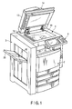
- FIG. 1 is a perspective view of an external configuration example of the digital multi-functional peripheral.
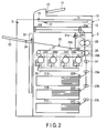
- FIG. 2 is a schematic sectional view of an internal configuration example of the digital multi-functional peripheral.
- the digital multi-functional peripheral includes a scanner 1, a printer 2, a finisher 3, and a control panel 4.
- the scanner 1 is set in an upper part of a main body of the digital multi-functional peripheral.
- the scanner 1 is an apparatus configured to optically read an image of an original.
- the scanner 1 includes an image reading unit 10 as a photoelectric conversion unit including a CCD line sensor configured to convert an image for one line in a main scanning direction in the original into image data.
- the image reading unit 10 reads an image of the entire original by scanning the original with the CCD line sensor in a sub-scanning direction of the original.
- the scanner 1 includes a original glass 11 and a original detection sensor 12.
- An original to be scanned by the image reading unit 10 is placed on the original glass 11.
- the image reading unit 10 scans the original on the original glass 11 via glass of the original glass 11.
- the original detection sensor 12 detects the original on the original glass 11.
- the original detection sensor 12 outputs a signal indicating presence or absence of the original on the original glass 11.
- the original detection sensor 12 detects a document size of the original on the original glass 11.
- the scanner 1 includes an auto document feeder (ADF) 13.
- the ADF 13 includes a sheet feeding tray 14 and a original tray sensor 15.
- the sheet feeding tray 14 stores originals to be read.
- the original tray sensor 15 detects whether the originals are present on the sheet feeding tray 14.
- the ADF 13 conveys the originals, which are stored by the sheet feeding tray 14, one by one.
- the scanner 1 reads an image of the original conveyed by the ADF 13.
- the ADF 13 also functions as a cover for an original placed on the original glass 11.
- the ADF 13 is attached on the original glass 11 in the main body of the digital multi-functional peripheral in a state in which the entire ADF 13 is openable and closable.
- the scanner 1 includes an platen sensor 16 configured to detect open and closed states of the ADF 13. If a user sets an original on the original glass 11, since the ADF 13 as the document cover is opened, the platen sensor 16 outputs a signal indicating the open state.
- the printer 2 includes sheet feeding cassettes 21A, 21B, and 21C.
- the sheet feeding cassettes 21A, 21B, and 21C store sheets as image formation media on which images are printed.
- the sheet feeding cassettes 21A, 21B, and 21C are detachably attachable to a lower part of the main body of the digital multi-functional peripheral.
- the sheet feeding cassettes 21A, 21B, and 21C respectively include sheet feeding rollers 22A, 22B, and 22C.
- the sheet feeding rollers 22A, 22B, and 22C extract the sheets from the sheet feeding cassettes 21A, 21B, and 21C one by one.
- a conveying unit 23 conveys a sheet in the printer 2.
- the conveying unit 23 includes plural conveying rollers 23a to 23f and a registration roller 24.
- the conveying unit 23 conveys the sheet extracted by the sheet feeding rollers 22A, 22B, and 22C to the registration roller 24.
- the registration roller 24 conveys the sheet to a transfer position at timing for transferring an image.
- Plural image forming units 25 respectively form images of colors (yellow, magenta, cyan, and black).
- An exposing unit 26 forms, on image bearing members in the image forming units 25 (25Y, 25M, 25C, and 25K), electrostatic latent images as images to be developed in the respective colors.
- An intermediate transfer belt 27 is an intermediate transfer member.
- the image forming units 25 (25Y, 25M, 25C, and 25K) form toner images on the intermediate transfer belt 27 by respectively developing the electrostatic latent images with toners of the colors (yellow, magenta, cyan, and black).
- the image forming units 25Y, 25M, 25C, and 25K transfer (primarily transfer) the toner images developed with the toners of the colors (yellow, magenta, cyan, and black) onto the intermediate transfer belt 27 while superimposing the toner images one on top of another.
- the intermediate transfer belt 27 holds a color image in which the toner images of the respective colors overlap one another.
- a transfer unit 28 transfers the color image formed with the toners of the plural colors on the intermediate transfer belt 27 onto a sheet in a secondary transfer position.
- the secondary transfer position is a position where the toner images on the intermediate transfer belt 27 are transferred onto the sheet.
- the secondary transfer position is a position where a supporting roller 28a and a secondary transfer roller 28b are opposed to each other.
- the registration roller 24 conveys the sheet to the secondary transfer position to be timed to coincide with the toner images on the intermediate transfer belt 27.
- the transfer unit 28 feeds the sheet having the toner images transferred thereon to a fuser 29.
- the fuser 29 fixes the toner images on the sheet.
- the fuser 29 heats, in a pressed state, the sheet having the toner image transferred thereon by the transfer unit 28.
- the fuser 29 conveys the sheet subjected to fixing processing to a exit tray 30 or the finisher 3.
- the exit tray 30 includes a sheet exit sensor 31a and a sheet sensor 31b.
- the sheet exit sensor 31a detects the output of the sheet to the exit tray 30.
- the sheet sensor 31b detects whether the sheet is present on the exit tray 30.
- the printer 2 shown in FIG. 2 is a printer of an electrophotographic system.
- the printer in this embodiment is not limited to the electrophotographic system.
- This embodiment can also be applied to a printer of a system other than the electrophotographic system such as an ink-jet system or a thermal transfer system.
- the finisher 3 includes a sheet discharge mechanism 32 configured to process a sheet having an image formed thereon by the printer 2.
- the finisher 3 includes a exit tray 33 on which the sheet having the image formed thereon by the printer 2 is accumulated.
- the sheet discharge mechanism 32 moves the exit tray 33 every time the printer 2 discharges sheets in one copy unit.
- the finisher 3 includes a sheet exit sensor 34.
- the sheet exit sensor 34 detects whether a sheet is placed on the exit tray 33.
- the finisher 3 may be a finisher having a function for stapling or a function for punching sheets accumulated on the exit tray 33.
- the control panel 4 is a user interface.
- the control panel 4 displays guidance and receives an input of an operation button or an icon. For example, the user inputs setting information in the control panel 4.
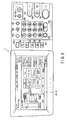
- FIG. 3 is a diagram of a configuration example of the control panel 4.
- the control panel 4 includes a display device 41, a touch panel 42, and plural operation buttons 43 (43a to 43p).
- the display device 41 displays guidance.
- the display device 41 has the touch panel 42 on a display screen.
- the touch panel 42 detects a section touched by the user on the display screen of the display device 41. The user can select, with the touch panel 42, an icon to be displayed by the display device 41.
- the plural operation buttons 43 include a menu button 43a, operation mode selection buttons (a copy button 43b, a filing box button 43c, a scan button 43d, a print button 43e, and a FAX button 43f), a set/register button (a setting button) 43g, an interrupt button 43h, a counter button 43i, a power saving button 43j, a power button 43k, a reset button 431, a stop button 43m, a start button 43n, a clear button 43o, a ten key 43p, and a setting hold button 43q.
- operation mode selection buttons a copy button 43b, a filing box button 43c, a scan button 43d, a print button 43e, and a FAX button 43f
- a set/register button (a setting button) 43g
- an interrupt button 43h a counter button 43i
- a power saving button 43j a power button 43k
- a reset button 431 a stop button 43m
- start button 43n a clear button 43o
- the menu button 43a is a button for instructing display of a menu screen. If the menu button 43a is pressed, the display device 41 displays a template often used by the user.
- the copy button 43b is a button for instructing a copy mode as an operation mode.
- the filing box button 43c is a button for instructing extraction of stored image data.
- the scan button 43d is a button for instructing a scan mode as the operation mode.
- the print button 43e is a button for instructing, for private printing or the like, a print mode as the operation mode.
- the FAX button 43f is a button for instructing a facsimile mode as the operation mode.
- the digital multi-functional peripheral For example, if the user uses the copy mode, the user presses the copy button 43b. If the user presses the copy button 43b, the digital multi-functional peripheral enters the copy mode. If the digital multi-functional peripheral is in the copy mode, the display device 41 displays a copy setting screen. Immediately after the user presses the copy button 43b, the display device 41 displays the copy setting screen on which default setting in the copy mode is reflected. In a state in which the copy setting screen is displayed, the user can change setting content to desired setting content. For example, the user can change the number of copies by pressing the ten key 43p. If the user presses the start button 43n, the digital multi-functional peripheral executes copying with the setting content displayed on the display device 41.
- the digital multi-functional peripheral If the user uses the scan mode, the user presses the scan button 43d. If the user presses the scan button 43d, the digital multi-functional peripheral enters the scan mode. If the digital multi-functional peripheral is in the scan mode, the display device 41 displays a scan setting screen. Immediately after the user presses the scan button 43d, the display device 41 displays the scan setting screen on which default setting in the scan mode is reflected. Setting content can be changed in a state in which the scan setting screen is displayed. If the user presses the start button 43n, the digital multi-functional peripheral executes scanning with the setting content displayed on the display device 41. For example, the digital multi-functional peripheral stores image data of a scanned original in a storage destination designated by the user.
- the display device 41 displays a facsimile setting screen. Immediately after the user presses the FAX button 43f, the display device 41 displays the facsimile setting screen on which default setting in the facsimile mode is reflected. Setting content can be changed in a state in which the facsimile setting screen is displayed. The user can input a telephone number as a destination of facsimile with the ten key 43p in a state in which the facsimile setting screen is displayed. If the user presses the start button 43n, the digital multi-functional peripheral transmits scanned image data to the telephone number displayed on the display device 41 by facsimile.
- the setting button 43g is a button for instructing registration of setting values if the user registers the setting values. For example, if the user presses the setting button 43g, the user can perform setting and registration of, for example, set time for auto-clearing setting content (set time for auto-clear), switching of a language displayed on a guide screen or the like, adjustment of brightness of a display screen of a display device, adjustment of gradation correction of a toner image, and adjustment of the position of the toner image with respect to a sheet. If the user presses the set/register button 43g, the user can perform setting and registration including a change of a default value for each of the operation modes such as the copy mode, the scan mode, and the facsimile mode. A setting value such as a default value set by the user after pressing the setting button 43g is stored in a memory 51 in a system controller 5 explained later.
- the interrupt button 43h is a button for instructing suspending printing under execution and executing another kind of processing.
- the counter button 43i is a button for instructing display of a counter.
- the power saving button 43j is a button for instructing a power saving mode as the operation mode.
- the power button 43k is a button for instructing turn-on of a power supply.
- the power button 43k may be a button for instructing shut-down.
- the reset button 431 is a button for instructing clearing of setting content and return to initial setting.
- the stop button 43m is a button for instructing the stop of operation.
- the start button 43n is a button for instructing the start of operation such as copying, scanning, and facsimile.
- the clear button 43o is a button for instructing correction of a numerical value input with the ten key 43p such as the number of copies.
- the ten key 43p is a button for inputting a numerical value such as the number of copies.
- the setting hold button 43q is a button for instructing maintenance of the present setting content. If the setting hold button 43q is on, the system control unit of the digital multi-functional peripheral maintains the present setting content. For example, in the auto-clear function, if the setting hold button 43q is on, the present setting content cannot be cleared. The user instructs the setting hold button 43q to be turned on or off. For example, the setting hold button 43q is turned on and off every time the user presses the setting hold button 43q. If the setting hold button 43q is on, the display device 41 displays a message for informing that the present setting content is maintained.
- the setting hold button 43q Even if the setting hold button 43q is on, if the operation mode selection button (the copy button 43b, the filing box button 43c, the scan button 43d, the print button 43e, or the FAX button 43f) is pressed, the setting hold button 43q is turned off. If the user presses the operation mode selection button while the setting hold button 43q is on, the display device 41 displays a setting screen on which default setting in the operation mode selected by the user is reflected.
- the operation mode selection button the copy button 43b, the filing box button 43c, the scan button 43d, the print button 43e, or the FAX button 43f
- the system control unit stores maintenance time in which the setting hold button 43q is maintained on.
- the setting hold button 43q may be turned off if the maintenance time elapses after the setting hold button 43q is turned on.
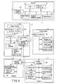
- FIG. 4 is a block diagram for explaining a configuration example of the control system in the digital multi-functional peripheral.
- the digital multi-functional peripheral includes the system controller 5 configured to control the entire apparatus.
- the system controller 5 is connected to the scanner 1, the printer 2, the finisher 3, and the control panel 4.
- the system controller 5 collectively controls the scanner 1, the printer 2, the finisher 3, and the control panel 4.
- the system controller 5 includes a main control unit (a processor) 50, an image memory 52, an image processor 53, a FAX controller 54, and an external interface (NW I/F) 55 and the like.
- the main control unit 50 controls the entire digital multi-functional peripheral.
- the main control unit 50 includes, for example, a processor, a RAM, and a ROM.
- the main control unit 50 is connected to control units of the scanner 1, the printer 2, the control panel 4, and the like.
- the main control unit 50 outputs operation instructions to the units and acquires various kinds of information from the units through bidirectional communication with the scanner 1, the printer 2, and the control panel 4.
- the main control unit 50 outputs setting information to the units on the basis of the present valid setting content.
- the main control unit 50 receives the input of detection signals of sensors and information indicating operation states and the like from the units.
- the main control unit 50 includes the memory 51 configured to store setting information and the like.
- the memory 51 includes a first memory 51a configured to store a first configuration as default setting and a second memory 51b configured to store a second configuration as the present setting content and information such as a flag indicating an operation state.
- the first memory 51a is a rewritable nonvolatile memory.
- the first memory 51a stores default settings (first configurations) in the copy mode, the scan mode, and the facsimile mode.
- the second memory 51b is a working memory configured to store information indicating an operation state, temporary data, or the like.
- the image memory 52 includes a hard disk driver (HDD) 52a and a page memory (PM) 52b.
- the HDD 52a is a large-capacity storage device.
- the HDD 52a stores plural image data.
- Setting data other than the image data, a control program, or the like may be stored in the HDD 52a.
- the page memory 52b is a memory for expanding image data to be processed.
- the image processor 53 processes the image data.
- the image processor 53 corrects, compresses, or expands the image data.
- the FAX controller 54 transmits and receives facsimile data.
- the external interface 55 is an interface configured to perform data communication with an external apparatus. For example, the external interface 55 receives the input of image data for printing from the external apparatus.
- the scanner 1 includes a scanner controller 61.
- the scanner controller 61 can communicate with the main control unit 50 of the system controller 5.
- the scanner controller 61 controls the image reading unit 10 and the ADF 13.
- the processor executes the control program stored in the memory, whereby the scanner controller 61 controls the units in the scanner 1.
- the scanner controller 61 outputs image data read by the image reading unit 10 to the system controller 5.
- the scanner controller 61 outputs a detection signal of the original tray sensor 15 and a detection signal of the platen sensor 16 to the main control unit 50.
- the printer 2 includes a printer controller 62.
- the printer controller 62 can communicate with the main control unit 50 of the system controller 5.
- the printer controller 62 controls the conveying unit 23, the image forming units 25, the exposing unit 26, the transfer unit 28, and the fuser 29 in the printer 2.
- the processor executes the control program stored in the memory, whereby the printer controller 62 controls the units in the printer 2.
- the printer controller 62 notifies the main control unit 50 of the system controller 5 of a processing state by the units in the printer 2.
- the printer controller 62 outputs a detection signal of the sheet sensor 31b to the main control unit 50.
- the printer controller 62 can communicate with a finisher controller 63 of the finisher 3.
- the printer controller 62 outputs an operation instruction to the finisher 3 and acquires various kinds of information from the finisher 3.
- the finisher 3 includes the finisher controller 63.
- the finisher controller 63 can communicate with the printer controller 62 of the printer 2.
- the finisher controller 63 controls the sheet discharge mechanism 32 in the finisher 3.
- the processor executes the control program stored in the memory, whereby the finisher controller 63 controls the units in the finisher 3.
- the finisher controller 63 notifies the printer 2 of a processing state in the finisher 3.
- the finisher controller 63 outputs a detection signal of the sheet exit sensor 34 to the printer controller 62.
- the printer controller 62 outputs a detection signal of the sheet exit sensor 34 to the main control unit 50.
- the control panel 4 includes a panel controller 64.
- the panel controller 64 can communicate with the main control unit 50 of the system controller 5.
- the panel controller 64 is connected to the display device 41, the touch panel 42, and the operation buttons 43.
- the panel controller 64 controls a display screen displayed by the display device 41.
- the panel controller 64 detects, according to a detection signal from the touch panel 42, a display section of an icon or the like touched by the user.
- the panel controller 64 outputs information indicating the icon touched by the user to the main control unit 50.
- the panel controller 64 outputs a signal indicating the operation button 43 pressed by the user to the main control unit 50.
- jobs including scanning of an original
- the jobs including scanning of an original there are copy processing, facsimile processing, scanning processing, and the like.
- the copy processing is executed in the copy mode instructed by the user with the copy button 43b.
- the facsimile processing is executed in the facsimile mode instructed by the user with the FAX button 43f.
- the scan processing is executed in the scan mode instructed by the user with the scan button 43d.
- the digital multi-functional peripheral has, in the copy mode, a sort mode for editing and printing images of plural originals.
- the digital multi-functional peripheral reads images of plural originals before starting printing.
- the digital multi-functional peripheral may read images of plural originals of all pages before starting printing.
- the digital multi-functional peripheral may read images of a part of plural originals before starting printing and read images of the remaining plural originals after starting printing of the read images. If an original is placed on the original glass 11, in order to read document images of all pages, the digital multi-functional peripheral urges, while checking presence or absence of originals of second and subsequent pages, the user to replace the original on the original glass 11 (set an original of the next page).
- the digital multi-functional peripheral starts printing without waiting for completion of scanning of an original.
- copy time for one original is short compared with that in the copying in the sort mode.
- default setting for the copy mode is often the non-sort mode.
- the copy mode remains in the sort mode even if the default setting is the non-sort mode.
- operation such as check of an original of the next page is necessary against the intension of the user.
- the digital multi-functional peripheral changes setting content to the default setting (e.g., the non-sort mode).
- the default setting e.g., the non-sort mode
- the digital multi-functional peripheral can change, without operation by the user, the copy mode to the non-sort mode with short copy time as the default setting.
- the digital multi-functional peripheral has an auto-clear function for clearing the present setting content and changing the setting content to the default setting if non-operation state exceeds a set time or if the operation mode is changed.
- the digital multi-functional peripheral maintains the present setting content if the user operates the control panel 4, if the user sets an original on the ADF 13, or if a sheet as a print result remains on the exit tray 30 or the exit tray 33.
- FIG. 5 is a flowchart for explaining the operation of auto-clear in the digital multi-functional peripheral.
- the memory 51 stores the operation flag, the opening and closing flag, and the standing time T.
- the main control unit 50 turns on the operation flag if the user touches the touch panel 42 of the control panel 4 or presses the operation button 43 (operates the control panel 4).
- the main control unit 50 turns on the opening and closing flag if the platen sensor 16 outputs a signal indicating an open state of the ADF 13, i.e., if the user opens the ADF 13.
- the main control unit 50 may turn on the opening and closing flag if the platen sensor 16 detects opening and closing of the ADF 13.
- the second memory 51b stores, as the present setting content (the second configuration), setting information input to the control panel 4 by the user.
- the main control unit 50 determines whether the setting hold button 43q is on (ACT 11). If the setting hold button 43q is on (YES in ACT 11), the main control unit 50 invalidates the auto-clear function and waits for the input of the start button 43n while maintaining the present setting content. However, even if the setting hold button 43q is on, the main control unit 50 updates, according to setting information input by the user with the control panel 4, the present setting content stored in the second memory 51b.
- the main control unit 50 determines whether the standing time T exceeds set time (e.g., 30 seconds) for auto-clear (ACT 12). The user may be able to set the set time for auto-clear with the control panel 4. If the standing time T exceeds the set time for auto-clear (YES in ACT 12), the main control unit 50 clears the present setting content stored in the second memory 51b (ACT 13). In clearing (resetting) the present setting content, the main control unit 50 rewrites the present setting content stored in the second memory 51b to the default setting in the present operation mode (e.g., the copy mode, the facsimile mode, or the scan mode). After clearing the setting information (changing the setting information to the default setting), the main control unit 50 displays a ready screen showing the setting content of the default setting on the display device 41 of the control panel 4 (ACT 14).
- set time e.g. 30 seconds
- the main control unit 50 determines whether the standing time T exceeds set time for auto-clear (ACT 12). The user may be able to
- the user may select whether the auto-clear function for clearing setting content according to the set time should be validated or invalidated. If the auto-clear function for clearing setting content according to the set time is invalidated, the main control unit 50 omits the processing in ACT 12.
- the main control unit 50 monitors whether the digital multi-functional peripheral is not operated by the user (a no-operation state). If there is an input to the operation buttons 43 of the control panel 4 or the touch panel 42, the operation flag is turned on. The main control unit 50 determines, according to whether the operation flag is on, whether the digital multi-functional peripheral is in the no-operation state (ACT 17).
- the main control unit 50 determines whether there in an input to the operation mode buttons 43b to 43f, the setting clear (reset) button 431, or the start button 43n (ACT 18, 19, or 20).
- the main control unit 50 turns off the setting hold button 43q (ACT 20). After turning off the setting hold button 43q, the main control unit 50 changes the operation mode, changes the present setting content stored in the second memory 51b to the default setting of the operation mode stored in the first memory 51a (ACT 13), and displays a ready screen in the operation mode on the display device 41 (ACT 14).
- the main control unit 50 changes the present setting content stored in the second memory 51b to the default setting of the operation mode corresponding to the pressed operation mode button.
- the main control unit 50 turns off the setting hold button 43q (ACT 20). After turning off the setting hold button 43q, the main control unit 50 changes the present setting content stored in the second memory 51b to the default setting of the present operation mode (ACT 13) and displays a ready screen on the display device 41 of the control panel 4 (ACT 14).
- the main control unit 50 executes a job with the present setting content stored in the second memory 51b (ACT 24).
- the main control unit 50 determines whether the opening and closing flag is on (ACT 22). If the opening and closing flag is on (YES in ACT 22), the main control unit 50 further determines, according to a detection signal of the original detection sensor 12, whether an original is present on the original glass 11 (ACT 23). If an original is present on the original glass 11 (YES in ACT 22), the main control unit 50 changes the present setting content stored in the second memory 51b to the default setting of the present operation mode stored in the first memory 51a (ACT 13) and displays a ready screen on the display device 41 of the control panel 4 (ACT 14).
- the main control unit 50 may clear the present setting content irrespectively of presence or absence of an original on the original glass 11. If the main control unit 50 determines that the opening and closing flag is on, the main control unit 50 may proceed to ACT 13 and clear the present setting content if elapsed time after the ADF 13 is closed exceeds auto-clear time for the document table glass. If the main control unit 50 determines that the opening and closing flag is on, the main control unit 50 may proceed to ACT 13 and clear the present setting content if elapsed time after the immediately preceding processing is started exceeds the auto-clear time for the document table glass.
- the main control unit 50 determines whether conditions for clearing the present setting content are satisfied.
- the main control unit 50 clears the present setting content and changes the present setting content to the default setting if the standing time (the no-operation state) exceeds the set time for auto-clear, if the user opens the ADF 13 and sets an original on the original glass 11, if the user presses the operation mode selection button, or if the user presses the setting clear button. If an original is set on the original glass 11 after the standing time (the no-operation state) exceeds the set time for auto-clear, the main control unit 50 may clear the present setting content and change the present setting content to the default setting.
- the main control unit 50 executes a job with the present setting content stored in the second memory 51b (ACT 24).
- the main control unit 50 determines whether an original conveyed by the ADF 13 is scanned or an original on the original glass 11 is scanned in the executed job (ACT 25).
- the main control unit 50 sets auto-clear time for the ADF (first time) as set time for auto-clear until the next job (ACT 26). If the original on the original glass 11 is scanned (NO in ACT 25), the main control unit 50 sets auto-clear time for the document table glass (second time) as set time for auto-clear until the next job (ACT 27). Different times can be set as the auto-clear time for the ADF (the first time) and the auto-clear time for the document table glass (the second time). The user can set the first time and the second time. For example, the auto-clear time for the document table glass (the second time) may be set shorter than the auto-clear time for the ADF (the first time).
- the immediately preceding user executes a job in the sort mode for continuously scanning and editing a right page and a left page of a book set on the original glass 11.
- the present setting content (the sort mode) is not cleared until the set time for auto-clear elapses.
- the digital multi-functional peripheral requests the user to check presence or absence of the next original. For the user who desires scanning in the non-sort mode, work for checking presence or absence of the next original is troublesome and useless work.
- the auto-clear time for the document table glass is set shorter than the auto-clear time for the ADF, it is easier to auto-clear setting content when the original on the original glass 11 is scanned. For example, whereas the auto-clear time for the ADF is set to 30 seconds, the auto-clear time for the document table glass is set to 5 to 15 seconds. Concerning the auto-clear time for the document table glass, setting content may be auto-cleared in 5 to 10 seconds with reference to time when the ADF 13 is closed or may be auto-cleared in about 15 seconds from the start of a job. By setting the auto-clear time for the document table glass shorter than the auto-clear time for the ADF, it is possible to provide a digital multi-functional peripheral that can perform setting with few mistakes and have high performance.
Landscapes
- Physics & Mathematics (AREA)
- General Physics & Mathematics (AREA)
- Engineering & Computer Science (AREA)
- Microelectronics & Electronic Packaging (AREA)
- Facsimiles In General (AREA)
- Control Or Security For Electrophotography (AREA)
Abstract
According to one embodiment, an image processing apparatus includes a document table (11), a document feeder (13), an opening sensor (16), an image reading unit (10), an operation unit (4), a first memory (51a), a second memory (51b), and a control unit (50). An original is placed on the document table. The document feeder can open and close an upper part of the document table and conveys the original. The opening sensor detects whether the document feeder opens the document table. The image reading unit generates image data of a first original conveyed by the document feeder or a second original placed on the document table. The operation unit receives the input of information indicating processing content for the image data. The first memory stores first configuration. The second memory stores second configuration corresponding to the information input to the operation unit. The control unit changes, if the opening sensor detects the opening of the document table, the second configuration stored in the second memory to the first configuration.
Description
- Embodiments described herein relate generally to an image processing apparatus and a method of controlling the image processing apparatus.
- An image processing apparatus such as a digital multi-functional peripheral often adopts an operation form in which the image processing apparatus is shared by a large number of users. In the digital multi-functional peripheral shared by plural users, in some case, setting content of a user who just finishes using the digital multi-functional peripheral remains. If setting performed by the preceding user remains, a user who uses the digital multi-functional peripheral next needs to operate an operation panel and clear the setting performed by the preceding user. In the digital multi-functional peripheral shared by plural users, even if default setting is acceptable, in some case, operation for clearing the setting performed by the preceding user is necessary before processing is started.
-
-
FIG. 1 is an external view of a configuration example of a digital multi-functional peripheral; -
FIG. 2 is a sectional view of the configuration example of the digital multi-functional peripheral; -
FIG. 3 is a diagram of a configuration example of a control panel; -
FIG. 4 is a block diagram for explaining a configuration example of a control system in the digital multi-functional peripheral; and -
FIG. 5 is a flowchart for explaining auto-clear of setting content. - In general, according to one embodiment, an image processing apparatus includes a document table, a document feeder, an opening sensor, an image reading unit, an operation unit, a first memory, a second memory, and a control unit. An original is placed on the document table. The document feeder is capable of opening and closing an upper part of the document table and conveys the original. The opening sensor detects whether the document feeder opens the document table. The image reading unit generates image data of a first original conveyed by the document feeder or a second original placed on the document table. The operation unit receives the input of information indicating processing content for the image data. The first memory stores a first configuration. The second memory stores a second configuration corresponding to the information input to the operation unit. The control unit changes, if the opening sensor detects the opening of the document table, the second configuration stored by the second memory to the first configuration.
- An embodiment is explained in detail below.
- First, the configuration of a digital multi-functional peripheral (MFP) as the image processing apparatus is explained.
-
FIG. 1 is a perspective view of an external configuration example of the digital multi-functional peripheral.FIG. 2 is a schematic sectional view of an internal configuration example of the digital multi-functional peripheral. As shown inFIG. 1 , the digital multi-functional peripheral includes ascanner 1, aprinter 2, afinisher 3, and acontrol panel 4. - The
scanner 1 is set in an upper part of a main body of the digital multi-functional peripheral. Thescanner 1 is an apparatus configured to optically read an image of an original. Thescanner 1 includes animage reading unit 10 as a photoelectric conversion unit including a CCD line sensor configured to convert an image for one line in a main scanning direction in the original into image data. Theimage reading unit 10 reads an image of the entire original by scanning the original with the CCD line sensor in a sub-scanning direction of the original. - The
scanner 1 includes aoriginal glass 11 and aoriginal detection sensor 12. An original to be scanned by theimage reading unit 10 is placed on theoriginal glass 11. Theimage reading unit 10 scans the original on theoriginal glass 11 via glass of theoriginal glass 11. Theoriginal detection sensor 12 detects the original on theoriginal glass 11. Theoriginal detection sensor 12 outputs a signal indicating presence or absence of the original on theoriginal glass 11. Theoriginal detection sensor 12 detects a document size of the original on theoriginal glass 11. - The
scanner 1 includes an auto document feeder (ADF) 13. The ADF 13 includes asheet feeding tray 14 and aoriginal tray sensor 15. The sheet feeding tray 14 stores originals to be read. Theoriginal tray sensor 15 detects whether the originals are present on thesheet feeding tray 14. The ADF 13 conveys the originals, which are stored by thesheet feeding tray 14, one by one. Thescanner 1 reads an image of the original conveyed by the ADF 13. - In the
scanner 1, the ADF 13 also functions as a cover for an original placed on theoriginal glass 11. The ADF 13 is attached on theoriginal glass 11 in the main body of the digital multi-functional peripheral in a state in which theentire ADF 13 is openable and closable. Thescanner 1 includes anplaten sensor 16 configured to detect open and closed states of the ADF 13. If a user sets an original on theoriginal glass 11, since theADF 13 as the document cover is opened, theplaten sensor 16 outputs a signal indicating the open state. - The
printer 2 includessheet feeding cassettes sheet feeding cassettes sheet feeding cassettes sheet feeding cassettes sheet feeding rollers sheet feeding rollers sheet feeding cassettes - A
conveying unit 23 conveys a sheet in theprinter 2. Theconveying unit 23 includesplural conveying rollers 23a to 23f and aregistration roller 24. Theconveying unit 23 conveys the sheet extracted by thesheet feeding rollers registration roller 24. Theregistration roller 24 conveys the sheet to a transfer position at timing for transferring an image. - Plural image forming units 25 (25Y, 25M, 25C, and 25K) respectively form images of colors (yellow, magenta, cyan, and black). An exposing
unit 26 forms, on image bearing members in the image forming units 25 (25Y, 25M, 25C, and 25K), electrostatic latent images as images to be developed in the respective colors. Anintermediate transfer belt 27 is an intermediate transfer member. The image forming units 25 (25Y, 25M, 25C, and 25K) form toner images on theintermediate transfer belt 27 by respectively developing the electrostatic latent images with toners of the colors (yellow, magenta, cyan, and black). - The
image forming units intermediate transfer belt 27 while superimposing the toner images one on top of another. Theintermediate transfer belt 27 holds a color image in which the toner images of the respective colors overlap one another. Atransfer unit 28 transfers the color image formed with the toners of the plural colors on theintermediate transfer belt 27 onto a sheet in a secondary transfer position. The secondary transfer position is a position where the toner images on theintermediate transfer belt 27 are transferred onto the sheet. The secondary transfer position is a position where a supportingroller 28a and asecondary transfer roller 28b are opposed to each other. Theregistration roller 24 conveys the sheet to the secondary transfer position to be timed to coincide with the toner images on theintermediate transfer belt 27. - The
transfer unit 28 feeds the sheet having the toner images transferred thereon to afuser 29. Thefuser 29 fixes the toner images on the sheet. The fuser 29 heats, in a pressed state, the sheet having the toner image transferred thereon by thetransfer unit 28. Thefuser 29 conveys the sheet subjected to fixing processing to aexit tray 30 or thefinisher 3. Theexit tray 30 includes asheet exit sensor 31a and asheet sensor 31b. Thesheet exit sensor 31a detects the output of the sheet to theexit tray 30. Thesheet sensor 31b detects whether the sheet is present on theexit tray 30. - The
printer 2 shown inFIG. 2 is a printer of an electrophotographic system. However, the printer in this embodiment is not limited to the electrophotographic system. This embodiment can also be applied to a printer of a system other than the electrophotographic system such as an ink-jet system or a thermal transfer system. - The
finisher 3 includes asheet discharge mechanism 32 configured to process a sheet having an image formed thereon by theprinter 2. Thefinisher 3 includes aexit tray 33 on which the sheet having the image formed thereon by theprinter 2 is accumulated. For example, thesheet discharge mechanism 32 moves theexit tray 33 every time theprinter 2 discharges sheets in one copy unit. Thefinisher 3 includes asheet exit sensor 34. Thesheet exit sensor 34 detects whether a sheet is placed on theexit tray 33. Thefinisher 3 may be a finisher having a function for stapling or a function for punching sheets accumulated on theexit tray 33. - The
control panel 4 is a user interface. Thecontrol panel 4 displays guidance and receives an input of an operation button or an icon. For example, the user inputs setting information in thecontrol panel 4. -
FIG. 3 is a diagram of a configuration example of thecontrol panel 4. In the example shown inFIG. 3 , thecontrol panel 4 includes adisplay device 41, atouch panel 42, and plural operation buttons 43 (43a to 43p). Thedisplay device 41 displays guidance. Thedisplay device 41 has thetouch panel 42 on a display screen. Thetouch panel 42 detects a section touched by the user on the display screen of thedisplay device 41. The user can select, with thetouch panel 42, an icon to be displayed by thedisplay device 41. - The
plural operation buttons 43 include amenu button 43a, operation mode selection buttons (acopy button 43b, afiling box button 43c, ascan button 43d, aprint button 43e, and aFAX button 43f), a set/register button (a setting button) 43g, an interruptbutton 43h, acounter button 43i, apower saving button 43j, apower button 43k, areset button 431, astop button 43m, astart button 43n, a clear button 43o, a ten key 43p, and asetting hold button 43q. - The
menu button 43a is a button for instructing display of a menu screen. If themenu button 43a is pressed, thedisplay device 41 displays a template often used by the user. Thecopy button 43b is a button for instructing a copy mode as an operation mode. Thefiling box button 43c is a button for instructing extraction of stored image data. Thescan button 43d is a button for instructing a scan mode as the operation mode. Theprint button 43e is a button for instructing, for private printing or the like, a print mode as the operation mode. TheFAX button 43f is a button for instructing a facsimile mode as the operation mode. - For example, if the user uses the copy mode, the user presses the
copy button 43b. If the user presses thecopy button 43b, the digital multi-functional peripheral enters the copy mode. If the digital multi-functional peripheral is in the copy mode, thedisplay device 41 displays a copy setting screen. Immediately after the user presses thecopy button 43b, thedisplay device 41 displays the copy setting screen on which default setting in the copy mode is reflected. In a state in which the copy setting screen is displayed, the user can change setting content to desired setting content. For example, the user can change the number of copies by pressing the ten key 43p. If the user presses thestart button 43n, the digital multi-functional peripheral executes copying with the setting content displayed on thedisplay device 41. - If the user uses the scan mode, the user presses the
scan button 43d. If the user presses thescan button 43d, the digital multi-functional peripheral enters the scan mode. If the digital multi-functional peripheral is in the scan mode, thedisplay device 41 displays a scan setting screen. Immediately after the user presses thescan button 43d, thedisplay device 41 displays the scan setting screen on which default setting in the scan mode is reflected. Setting content can be changed in a state in which the scan setting screen is displayed. If the user presses thestart button 43n, the digital multi-functional peripheral executes scanning with the setting content displayed on thedisplay device 41. For example, the digital multi-functional peripheral stores image data of a scanned original in a storage destination designated by the user. - If the user uses the facsimile mode, the user presses the
FAX button 43f. If the user presses theFAX button 43f, the digital multi-functional peripheral enters the facsimile mode. If the digital multi-functional peripheral is in the facsimile mode, thedisplay device 41 displays a facsimile setting screen. Immediately after the user presses theFAX button 43f, thedisplay device 41 displays the facsimile setting screen on which default setting in the facsimile mode is reflected. Setting content can be changed in a state in which the facsimile setting screen is displayed. The user can input a telephone number as a destination of facsimile with the ten key 43p in a state in which the facsimile setting screen is displayed. If the user presses thestart button 43n, the digital multi-functional peripheral transmits scanned image data to the telephone number displayed on thedisplay device 41 by facsimile. - The
setting button 43g is a button for instructing registration of setting values if the user registers the setting values. For example, if the user presses thesetting button 43g, the user can perform setting and registration of, for example, set time for auto-clearing setting content (set time for auto-clear), switching of a language displayed on a guide screen or the like, adjustment of brightness of a display screen of a display device, adjustment of gradation correction of a toner image, and adjustment of the position of the toner image with respect to a sheet. If the user presses the set/register button 43g, the user can perform setting and registration including a change of a default value for each of the operation modes such as the copy mode, the scan mode, and the facsimile mode.
A setting value such as a default value set by the user after pressing thesetting button 43g is stored in amemory 51 in asystem controller 5 explained later. - The interrupt
button 43h is a button for instructing suspending printing under execution and executing another kind of processing. Thecounter button 43i is a button for instructing display of a counter. Thepower saving button 43j is a button for instructing a power saving mode as the operation mode. Thepower button 43k is a button for instructing turn-on of a power supply. Thepower button 43k may be a button for instructing shut-down. Thereset button 431 is a button for instructing clearing of setting content and return to initial setting. Thestop button 43m is a button for instructing the stop of operation. Thestart button 43n is a button for instructing the start of operation such as copying, scanning, and facsimile. The clear button 43o is a button for instructing correction of a numerical value input with the ten key 43p such as the number of copies. The ten key 43p is a button for inputting a numerical value such as the number of copies. - The
setting hold button 43q is a button for instructing maintenance of the present setting content. If thesetting hold button 43q is on, the system control unit of the digital multi-functional peripheral maintains the present setting content. For example, in the auto-clear function, if thesetting hold button 43q is on, the present setting content cannot be cleared. The user instructs thesetting hold button 43q to be turned on or off. For example, thesetting hold button 43q is turned on and off every time the user presses thesetting hold button 43q. If thesetting hold button 43q is on, thedisplay device 41 displays a message for informing that the present setting content is maintained. - Even if the
setting hold button 43q is on, if the operation mode selection button (thecopy button 43b, thefiling box button 43c, thescan button 43d, theprint button 43e, or theFAX button 43f) is pressed, thesetting hold button 43q is turned off. If the user presses the operation mode selection button while thesetting hold button 43q is on, thedisplay device 41 displays a setting screen on which default setting in the operation mode selected by the user is reflected. - The system control unit stores maintenance time in which the
setting hold button 43q is maintained on.
Thesetting hold button 43q may be turned off if the maintenance time elapses after thesetting hold button 43q is turned on. - The configuration of a control system in the digital multi-functional peripheral configured as above is explained below.
-
FIG. 4 is a block diagram for explaining a configuration example of the control system in the digital multi-functional peripheral. - The digital multi-functional peripheral includes the
system controller 5 configured to control the entire apparatus. Thesystem controller 5 is connected to thescanner 1, theprinter 2, thefinisher 3, and thecontrol panel 4. Thesystem controller 5 collectively controls thescanner 1, theprinter 2, thefinisher 3, and thecontrol panel 4. - The
system controller 5 includes a main control unit (a processor) 50, animage memory 52, animage processor 53, aFAX controller 54, and an external interface (NW I/F) 55 and the like. - The
main control unit 50 controls the entire digital multi-functional peripheral. Themain control unit 50 includes, for example, a processor, a RAM, and a ROM. Themain control unit 50 is connected to control units of thescanner 1, theprinter 2, thecontrol panel 4, and the like. Themain control unit 50 outputs operation instructions to the units and acquires various kinds of information from the units through bidirectional communication with thescanner 1, theprinter 2, and thecontrol panel 4. For example, themain control unit 50 outputs setting information to the units on the basis of the present valid setting content. Themain control unit 50 receives the input of detection signals of sensors and information indicating operation states and the like from the units. - The
main control unit 50 includes thememory 51 configured to store setting information and the like. Thememory 51 includes afirst memory 51a configured to store a first configuration as default setting and asecond memory 51b configured to store a second configuration as the present setting content and information such as a flag indicating an operation state. Thefirst memory 51a is a rewritable nonvolatile memory. Thefirst memory 51a stores default settings (first configurations) in the copy mode, the scan mode, and the facsimile mode. Thesecond memory 51b is a working memory configured to store information indicating an operation state, temporary data, or the like. - The
image memory 52 includes a hard disk driver (HDD) 52a and a page memory (PM) 52b. TheHDD 52a is a large-capacity storage device. For example, theHDD 52a stores plural image data. Setting data other than the image data, a control program, or the like may be stored in theHDD 52a. Thepage memory 52b is a memory for expanding image data to be processed. Theimage processor 53 processes the image data. Theimage processor 53 corrects, compresses, or expands the image data. TheFAX controller 54 transmits and receives facsimile data. Theexternal interface 55 is an interface configured to perform data communication with an external apparatus. For example, theexternal interface 55 receives the input of image data for printing from the external apparatus. - The
scanner 1 includes ascanner controller 61. Thescanner controller 61 can communicate with themain control unit 50 of thesystem controller 5. Thescanner controller 61 controls theimage reading unit 10 and theADF 13. The processor executes the control program stored in the memory, whereby thescanner controller 61 controls the units in thescanner 1. Thescanner controller 61 outputs image data read by theimage reading unit 10 to thesystem controller 5. Thescanner controller 61 outputs a detection signal of theoriginal tray sensor 15 and a detection signal of theplaten sensor 16 to themain control unit 50. - The
printer 2 includes aprinter controller 62. Theprinter controller 62 can communicate with themain control unit 50 of thesystem controller 5. Theprinter controller 62 controls the conveyingunit 23, theimage forming units 25, the exposingunit 26, thetransfer unit 28, and thefuser 29 in theprinter 2. The processor executes the control program stored in the memory, whereby theprinter controller 62 controls the units in theprinter 2. Theprinter controller 62 notifies themain control unit 50 of thesystem controller 5 of a processing state by the units in theprinter 2. Theprinter controller 62 outputs a detection signal of thesheet sensor 31b to themain control unit 50. Theprinter controller 62 can communicate with afinisher controller 63 of thefinisher 3. Theprinter controller 62 outputs an operation instruction to thefinisher 3 and acquires various kinds of information from thefinisher 3. - The
finisher 3 includes thefinisher controller 63. Thefinisher controller 63 can communicate with theprinter controller 62 of theprinter 2. Thefinisher controller 63 controls thesheet discharge mechanism 32 in thefinisher 3. The processor executes the control program stored in the memory, whereby thefinisher controller 63 controls the units in thefinisher 3. Thefinisher controller 63 notifies theprinter 2 of a processing state in thefinisher 3. Thefinisher controller 63 outputs a detection signal of thesheet exit sensor 34 to theprinter controller 62. Theprinter controller 62 outputs a detection signal of thesheet exit sensor 34 to themain control unit 50. - The
control panel 4 includes apanel controller 64. Thepanel controller 64 can communicate with themain control unit 50 of thesystem controller 5. Thepanel controller 64 is connected to thedisplay device 41, thetouch panel 42, and theoperation buttons 43. Thepanel controller 64 controls a display screen displayed by thedisplay device 41. Thepanel controller 64 detects, according to a detection signal from thetouch panel 42, a display section of an icon or the like touched by the user. Thepanel controller 64 outputs information indicating the icon touched by the user to themain control unit 50. Thepanel controller 64 outputs a signal indicating theoperation button 43 pressed by the user to themain control unit 50. - Auto-clear for setting information in the digital multi-functional peripheral is explained below.
- First, setting for various kinds of processing (jobs) including scanning of an original is explained. For example, in the digital multi-functional peripheral, as the jobs including scanning of an original, there are copy processing, facsimile processing, scanning processing, and the like. The copy processing is executed in the copy mode instructed by the user with the
copy button 43b. The facsimile processing is executed in the facsimile mode instructed by the user with theFAX button 43f. The scan processing is executed in the scan mode instructed by the user with thescan button 43d. - For example, the digital multi-functional peripheral has, in the copy mode, a sort mode for editing and printing images of plural originals. In the sort mode, the digital multi-functional peripheral reads images of plural originals before starting printing. The digital multi-functional peripheral may read images of plural originals of all pages before starting printing. The digital multi-functional peripheral may read images of a part of plural originals before starting printing and read images of the remaining plural originals after starting printing of the read images. If an original is placed on the
original glass 11, in order to read document images of all pages, the digital multi-functional peripheral urges, while checking presence or absence of originals of second and subsequent pages, the user to replace the original on the original glass 11 (set an original of the next page). - In copying in a non-sort mode, the digital multi-functional peripheral starts printing without waiting for completion of scanning of an original. In the copying in the non-sort mode, copy time for one original is short compared with that in the copying in the sort mode. In the digital multi-functional peripheral, in order to reduce the copy time for one original, default setting for the copy mode is often the non-sort mode. However, if the preceding user performs copying in the sort mode, unless setting of the sort mode is cleared, the copy mode remains in the sort mode even if the default setting is the non-sort mode. Further, when an original placed on the
original glass 11 is read, if the setting of the non-sort mode unintended by the user remains, operation such as check of an original of the next page is necessary against the intension of the user. - If the user opens the
ADF 13 and sets an original on theoriginal glass 11, the digital multi-functional peripheral according to this embodiment changes setting content to the default setting (e.g., the non-sort mode). As a result, if the user opens theADF 13 and sets an original on theoriginal glass 11, the digital multi-functional peripheral can change, without operation by the user, the copy mode to the non-sort mode with short copy time as the default setting. - The digital multi-functional peripheral according to this embodiment has an auto-clear function for clearing the present setting content and changing the setting content to the default setting if non-operation state exceeds a set time or if the operation mode is changed. In the auto-clear function of the digital multi-functional peripheral according to this embodiment, the digital multi-functional peripheral maintains the present setting content if the user operates the
control panel 4, if the user sets an original on theADF 13, or if a sheet as a print result remains on theexit tray 30 or theexit tray 33. -
FIG. 5 is a flowchart for explaining the operation of auto-clear in the digital multi-functional peripheral. - When one job ends, the
main control unit 50 turns off an operation flag and an opening and closing flag and initializes a standing time (elapsed time) T (T=0) (ACT 10). Thememory 51 stores the operation flag, the opening and closing flag, and the standing time T. Themain control unit 50 turns on the operation flag if the user touches thetouch panel 42 of thecontrol panel 4 or presses the operation button 43 (operates the control panel 4). Themain control unit 50 turns on the opening and closing flag if theplaten sensor 16 outputs a signal indicating an open state of theADF 13, i.e., if the user opens theADF 13. Themain control unit 50 may turn on the opening and closing flag if theplaten sensor 16 detects opening and closing of theADF 13. Thesecond memory 51b stores, as the present setting content (the second configuration), setting information input to thecontrol panel 4 by the user. - If the flags and the standing time T are initialized, the
main control unit 50 determines whether thesetting hold button 43q is on (ACT 11). If thesetting hold button 43q is on (YES in ACT 11), themain control unit 50 invalidates the auto-clear function and waits for the input of thestart button 43n while maintaining the present setting content. However, even if thesetting hold button 43q is on, themain control unit 50 updates, according to setting information input by the user with thecontrol panel 4, the present setting content stored in thesecond memory 51b. - If the
main control unit 50 determines that thesetting hold button 43q is not on (NO in ACT 11), themain control unit 50 determines whether the standing time T exceeds set time (e.g., 30 seconds) for auto-clear (ACT 12). The user may be able to set the set time for auto-clear with thecontrol panel 4. If the standing time T exceeds the set time for auto-clear (YES in ACT 12), themain control unit 50 clears the present setting content stored in thesecond memory 51b (ACT 13). In clearing (resetting) the present setting content, themain control unit 50 rewrites the present setting content stored in thesecond memory 51b to the default setting in the present operation mode (e.g., the copy mode, the facsimile mode, or the scan mode). After clearing the setting information (changing the setting information to the default setting), themain control unit 50 displays a ready screen showing the setting content of the default setting on thedisplay device 41 of the control panel 4 (ACT 14). - The user may select whether the auto-clear function for clearing setting content according to the set time should be validated or invalidated. If the auto-clear function for clearing setting content according to the set time is invalidated, the
main control unit 50 omits the processing inACT 12. - If the standing time T is within the set time for auto-clear (NO in ACT 12), the
main control unit 50 determines whether an original is present on thesheet feeding tray 14 of the ADF 13 (ACT 15). Themain control unit 50 determines, according to a detection signal of theoriginal tray sensor 15, whether an original is present on thesheet feeding tray 14. If themain control unit 50 determines that a sheet is present on thesheet feeding tray 14 of the ADF 13 (YES in ACT 15), themain control unit 50 returns toACT 10 and initializes the standing time T (T=0). If the user places an original on thesheet feeding tray 14 of theADF 13, the digital multi-functional peripheral according to this embodiment maintains the present setting content stored in thesecond memory 51b determining that the user desires to process an image of the original with the present setting content. - If the standing time T is within the set time for auto-clear (NO in ACT 12), the
main control unit 50 determines whether a sheet is present on theexit tray 30 or the exit tray 33 (ACT 16). Themain control unit 50 determines, with thesheet sensor 31b, whether a sheet is present on theexit tray 30. Themain control unit 50 determines, with thesheet exit sensor 34, whether a sheet is present on theexit tray 33 of thefinisher 3. If themain control unit 50 determines that a sheet is present on theexit tray 30 or the exit tray 33 (YES in ACT 16), themain control unit 50 returns toACT 10 and initializes the standing time T (T=0). If a sheet remains on theexit tray 30 or theexit tray 33, the digital multi-functional peripheral according to this embodiment maintains the present setting content stored in thesecond memory 51b determining that the user does not change. - If the standing time T is within the set time for auto-clear (NO in ACT 12), the
main control unit 50 monitors whether the digital multi-functional peripheral is not operated by the user (a no-operation state). If there is an input to theoperation buttons 43 of thecontrol panel 4 or thetouch panel 42, the operation flag is turned on. Themain control unit 50 determines, according to whether the operation flag is on, whether the digital multi-functional peripheral is in the no-operation state (ACT 17). - If the operation flag is on (YES in ACT 17), the
main control unit 50 determines whether there in an input to theoperation mode buttons 43b to 43f, the setting clear (reset)button 431, or thestart button 43n (ACT 18, 19, or 20). - If there is an input to the
operation mode buttons 43b to 43f, i.e., if the user presses any one of theoperation mode buttons 43b to 43f (YES in ACT 18), themain control unit 50 turns off thesetting hold button 43q (ACT 20). After turning off thesetting hold button 43q, themain control unit 50 changes the operation mode, changes the present setting content stored in thesecond memory 51b to the default setting of the operation mode stored in thefirst memory 51a (ACT 13), and displays a ready screen in the operation mode on the display device 41 (ACT 14). Even if thesetting hold button 43q is on, if there is an input to theoperation mode buttons 43b to 43f, themain control unit 50 changes the present setting content stored in thesecond memory 51b to the default setting of the operation mode corresponding to the pressed operation mode button. - If there is an input to the setting clear (reset)
button 431, i.e., if the user presses the setting clear (reset)button 431 for clearing the present setting content (YES in ACT 19), themain control unit 50 turns off thesetting hold button 43q (ACT 20). After turning off thesetting hold button 43q, themain control unit 50 changes the present setting content stored in thesecond memory 51b to the default setting of the present operation mode (ACT 13) and displays a ready screen on thedisplay device 41 of the control panel 4 (ACT 14). - If there is an input to the
start button 43n, i.e., if the user presses thestart button 43n (YES in ACT 21), themain control unit 50 executes a job with the present setting content stored in thesecond memory 51b (ACT 24). - If there is an input to the
operation buttons 43 other than theoperation mode buttons 43b to 43f, the setting clear (reset)button 431, and thestart button 43n or thetouch panel 42, i.e., if the user operates the control panel 4 (NO in ACT 21), themain control unit 50 returns toACT 10, turns off the operation flag, and initializes the standing time T (T=0). If there is an input to thecontrol panel 4, the digital multi-functional peripheral according to this embodiment maintains the present setting content stored in thesecond memory 51b determining that the user is performing work such as setting of a processing mode for a scan image or a change of setting content such as a change of the number of prints. Themain control unit 50 stores setting content input to thecontrol panel 4 by the user in thesecond memory 51b as the present setting content. - If the standing time T is within the set time for auto-clear (NO in ACT 12), the
main control unit 50 determines whether the opening and closing flag is on (ACT 22). If the opening and closing flag is on (YES in ACT 22), themain control unit 50 further determines, according to a detection signal of theoriginal detection sensor 12, whether an original is present on the original glass 11 (ACT 23). If an original is present on the original glass 11 (YES in ACT 22), themain control unit 50 changes the present setting content stored in thesecond memory 51b to the default setting of the present operation mode stored in thefirst memory 51a (ACT 13) and displays a ready screen on thedisplay device 41 of the control panel 4 (ACT 14). - If the
ADF 13 is in the open state (the opening and closing flag is on), themain control unit 50 may clear the present setting content irrespectively of presence or absence of an original on theoriginal glass 11. If themain control unit 50 determines that the opening and closing flag is on, themain control unit 50 may proceed toACT 13 and clear the present setting content if elapsed time after theADF 13 is closed exceeds auto-clear time for the document table glass. If themain control unit 50 determines that the opening and closing flag is on, themain control unit 50 may proceed toACT 13 and clear the present setting content if elapsed time after the immediately preceding processing is started exceeds the auto-clear time for the document table glass. - In ACTS 12, 22, 23, 18, and 19, the
main control unit 50 determines whether conditions for clearing the present setting content are satisfied. In the digital multi-functional peripheral according to this embodiment, themain control unit 50 clears the present setting content and changes the present setting content to the default setting if the standing time (the no-operation state) exceeds the set time for auto-clear, if the user opens theADF 13 and sets an original on theoriginal glass 11, if the user presses the operation mode selection button, or if the user presses the setting clear button. If an original is set on theoriginal glass 11 after the standing time (the no-operation state) exceeds the set time for auto-clear, themain control unit 50 may clear the present setting content and change the present setting content to the default setting. - If the user presses the
start button 43n (YES in ACT 21), themain control unit 50 executes a job with the present setting content stored in thesecond memory 51b (ACT 24). When the job ends, themain control unit 50 determines whether an original conveyed by theADF 13 is scanned or an original on theoriginal glass 11 is scanned in the executed job (ACT 25). - If the original conveyed by the
ADF 13 is scanned (YES in ACT 25), themain control unit 50 sets auto-clear time for the ADF (first time) as set time for auto-clear until the next job (ACT 26). If the original on theoriginal glass 11 is scanned (NO in ACT 25), themain control unit 50 sets auto-clear time for the document table glass (second time) as set time for auto-clear until the next job (ACT 27). Different times can be set as the auto-clear time for the ADF (the first time) and the auto-clear time for the document table glass (the second time). The user can set the first time and the second time. For example, the auto-clear time for the document table glass (the second time) may be set shorter than the auto-clear time for the ADF (the first time). - For example, it is assumed that the immediately preceding user executes a job in the sort mode for continuously scanning and editing a right page and a left page of a book set on the
original glass 11. Unless the next user performs operation for clearing setting, even if the user desires to scan an original set on theoriginal glass 11 in the non-sort mode, the present setting content (the sort mode) is not cleared until the set time for auto-clear elapses. In scanning the original on theoriginal glass 11 in the sort mode, the digital multi-functional peripheral requests the user to check presence or absence of the next original. For the user who desires scanning in the non-sort mode, work for checking presence or absence of the next original is troublesome and useless work. - If the auto-clear time for the document table glass is set shorter than the auto-clear time for the ADF, it is easier to auto-clear setting content when the original on the
original glass 11 is scanned. For example, whereas the auto-clear time for the ADF is set to 30 seconds, the auto-clear time for the document table glass is set to 5 to 15 seconds. Concerning the auto-clear time for the document table glass, setting content may be auto-cleared in 5 to 10 seconds with reference to time when theADF 13 is closed or may be auto-cleared in about 15 seconds from the start of a job. By setting the auto-clear time for the document table glass shorter than the auto-clear time for the ADF, it is possible to provide a digital multi-functional peripheral that can perform setting with few mistakes and have high performance. - While certain embodiments have been described, these embodiments have been presented by way of example only, and are not intended to limit the scope of the inventions. Indeed, the novel methods and systems described herein may be embodied in a variety of other forms; furthermore, various omissions, substitutions and changes in the form of the methods and systems described herein may be made without departing from the spirit of the inventions. The accompanying claims and their equivalents are intended to cover such forms or modifications as would fall within the scope and spirit of the inventions.
Claims (12)
- An image processing apparatus, characterized by comprising:a document table (11) on which an original is placed;a document feeder (13) configured to be capable of opening and closing an upper part of the document table and convey the original;an opening sensor (16) configured to detect whether the document feeder opens the document table;an image reading unit (10) configured to generate image data of a first original conveyed by the document feeder or a second original placed on the document table;an operation unit (4) configured to receive input of information indicating processing content for the image data;a first memory (51a) configured to store a first configuration;a second memory (51b) configured to store a second configuration corresponding to the information input to the operation unit; anda control unit (50) configured to change the second configuration stored in the second memory to the first configuration, if the opening sensor detects the opening of the document table.
- The apparatus according to claim 1, further comprising a document sensor (12) configured to detect presence of an original on the document table, characterized in that
the control unit (50) changes the second configuration stored in the second memory to the first configuration, if the opening sensor detects the opening of the document table and the document sensor detects an original on the document table. - The apparatus according to claim 1, further comprising plural operation mode buttons (43b-43f), characterized in that
the first memory (51a) stores a plural first configuration for each of plural operation modes, and
the control unit (50) changes the second configuration stored in the second memory (51b) to the first configuration of the operation mode corresponding to the pressed button, if there is an input to the operation mode buttons. - The apparatus according to claim 1, further comprising a hold button (43q) for instructing maintenance of the second configuration stored in the second memory (51b), characterized in that
the control unit (50) maintains the second configuration stored in the second memory, if the hold button is on, even if the opening sensor detects the opening of the document table. - The apparatus according to claim 3, further comprising a hold button (43q) for instructing maintaining the second configuration stored in the second memory (51b), characterized in that
the control unit (50) turns off the hold button if there is an input to the operation mode button. - The apparatus according to claim 1, further comprising a processing unit (2, 53, 54, 55) configured to process image data read by the image reading unit according to the second configuration stored in the second memory (51b), characterized in that
the control unit (50) changes the second configuration stored in the second memory to the first configuration, if elapsed time of a state without operation of the operation unit exceeds set time for auto-clear after the processing by the processing unit ends. - The apparatus according to claim 6, further comprising a sheet feeding sensor (15) configured to detect an original set on the document feeder, characterized in that
the control unit (50) initializes the elapsed time compared with the set time for auto-clear, if the sheet feeding sensor detects an original after the processing by the processing unit ends. - The apparatus according to claim 6, characterized in that
the processing unit is an image forming unit (2) configured to print image data read by the image reading unit on a sheet,
the apparatus further comprises a sheet discharge unit (3, 30) configured to discharge the sheet having the image data printed thereon by the image forming unit, and a sheet discharge sensor (31, 34) configured to detect a sheet on the sheet discharge unit, and
the control unit (50) initializes the elapsed time compared with the set time for auto-clear, if the sheet discharge unit sensor detects a sheet after the processing by the processing unit ends. - The apparatus according to claim 6, characterized in that the control unit (50) sets first time as the set time for auto-clear if the image reading unit scans an original on the document feeder in the processing executed by the processing unit and sets second time shorter than the first time as the set time for auto-clear if the image reading unit scans an original on the document table in the processing executed in the processing unit.
- The apparatus according to claim 9, characterized in that the control unit (50) changes the second configuration stored in the second memory to the first configuration, if elapsed time after the opening sensor detects that the document feeder is closed exceeds the second time.
- A method for job execution, characterized by comprising:storing a first configuration to be employed in the job execution in a first memory (51a);storing a second configuration to be employed in the job execution instead of the first configuration, the second configuration corresponding to input of information indicating processing content for the image data in a second memory (51b);detecting (ACT22) a state of a document feeder capable of opening and closing an upper part of a document table (11); andemploying (ACT13) the first configuration for the job execution instead of the second configuration if the opening is detected.
- The method of claim 11, characterized in that the job execution includes a scanning by an image reading unit (10) configured to generate image data of a first original conveyed by the document feeder and a second original placed on the document table.
Applications Claiming Priority (1)
| Application Number | Priority Date | Filing Date | Title |
|---|---|---|---|
| US21884309P | 2009-06-19 | 2009-06-19 |
Publications (1)
| Publication Number | Publication Date |
|---|---|
| EP2264545A2 true EP2264545A2 (en) | 2010-12-22 |
Family
ID=42732116
Family Applications (1)
| Application Number | Title | Priority Date | Filing Date |
|---|---|---|---|
| EP10166073A Withdrawn EP2264545A2 (en) | 2009-06-19 | 2010-06-15 | Image processing apparatus and method of controlling the image processing apparatus |
Country Status (4)
| Country | Link |
|---|---|
| US (1) | US20100321731A1 (en) |
| EP (1) | EP2264545A2 (en) |
| JP (1) | JP5538084B2 (en) |
| CN (1) | CN101931726A (en) |
Families Citing this family (8)
| Publication number | Priority date | Publication date | Assignee | Title |
|---|---|---|---|---|
| JP6226807B2 (en) * | 2014-04-18 | 2017-11-08 | キヤノン株式会社 | Program, mobile terminal, control method, and image processing system |
| JP6778998B2 (en) * | 2015-08-05 | 2020-11-04 | キヤノン株式会社 | Image reader, its control method, and program |
| JP6152522B2 (en) * | 2016-10-25 | 2017-06-28 | 和之 坪内 | Image forming apparatus |
| US11277534B2 (en) * | 2017-08-18 | 2022-03-15 | Kyocera Document Solutions Inc. | Image reading apparatus and method for controlling image reading apparatus |
| JP6957296B2 (en) * | 2017-09-29 | 2021-11-02 | キヤノン株式会社 | Image processing device and control method of image processing device, and program |
| US10602008B1 (en) * | 2018-11-21 | 2020-03-24 | Toshiba Tec Kabushiki Kaisha | Image forming apparatus and image forming method |
| CN109495666A (en) * | 2018-11-22 | 2019-03-19 | 宝鸡文理学院 | A kind of information processing unit |
| JP7757759B2 (en) * | 2021-12-10 | 2025-10-22 | コニカミノルタ株式会社 | Image forming apparatus, sheet type setting method, and sheet type setting program |
Family Cites Families (14)
| Publication number | Priority date | Publication date | Assignee | Title |
|---|---|---|---|---|
| JPH02170174A (en) * | 1988-12-23 | 1990-06-29 | Toshiba Corp | Image forming device |
| JP3598772B2 (en) * | 1997-11-11 | 2004-12-08 | ミノルタ株式会社 | Image forming device |
| JP2001203834A (en) * | 2000-01-19 | 2001-07-27 | Canon Inc | Composite device, control method thereof, information processing system, and storage medium |
| JP4366341B2 (en) * | 2004-07-26 | 2009-11-18 | キヤノン株式会社 | Data processing method, data processing system, computer program, and storage medium |
| JP4721735B2 (en) * | 2005-03-15 | 2011-07-13 | 株式会社リコー | Document reading apparatus, image processing apparatus, image forming apparatus, and copying apparatus |
| JP4364156B2 (en) * | 2005-04-18 | 2009-11-11 | ブラザー工業株式会社 | Compound machine |
| JP5025192B2 (en) * | 2005-09-16 | 2012-09-12 | 株式会社リコー | Apparatus, information processing method, information processing program, and recording medium |
| JP4543334B2 (en) * | 2006-03-31 | 2010-09-15 | ブラザー工業株式会社 | Printing apparatus and printing apparatus setting changing method |
| JP2008139402A (en) * | 2006-11-30 | 2008-06-19 | Kyocera Mita Corp | Image forming apparatus |
| JP4315976B2 (en) * | 2006-12-28 | 2009-08-19 | シャープ株式会社 | Data processing device |
| US7764922B2 (en) * | 2007-02-14 | 2010-07-27 | Kabushiki Kaisha Toshiba | Image forming apparatus with printed-paper storing function and printed-paper storing method thereof |
| JP2008306707A (en) * | 2007-05-07 | 2008-12-18 | Ricoh Co Ltd | Image reading apparatus, image forming apparatus, and light source lighting control method |
| JP2009049876A (en) * | 2007-08-22 | 2009-03-05 | Kyocera Mita Corp | Image reading device |
| JP2009152703A (en) * | 2007-12-19 | 2009-07-09 | Konica Minolta Business Technologies Inc | Image processing apparatus |
-
2010
- 2010-06-15 US US12/816,279 patent/US20100321731A1/en not_active Abandoned
- 2010-06-15 EP EP10166073A patent/EP2264545A2/en not_active Withdrawn
- 2010-06-18 CN CN2010102073460A patent/CN101931726A/en active Pending
- 2010-06-18 JP JP2010139706A patent/JP5538084B2/en not_active Expired - Fee Related
Non-Patent Citations (1)
| Title |
|---|
| None |
Also Published As
| Publication number | Publication date |
|---|---|
| US20100321731A1 (en) | 2010-12-23 |
| JP5538084B2 (en) | 2014-07-02 |
| JP2011002837A (en) | 2011-01-06 |
| CN101931726A (en) | 2010-12-29 |
Similar Documents
| Publication | Publication Date | Title |
|---|---|---|
| US8985582B2 (en) | Sheet processing apparatus, method for controlling sheet processing apparatus, and storage medium | |
| JP5852440B2 (en) | Printing apparatus, control method therefor, and program | |
| JP5898477B2 (en) | Printing apparatus, control method therefor, and program | |
| US20100321731A1 (en) | Image processing apparatus and method of controlling the image processing apparatus | |
| US20110199623A1 (en) | Image processing apparatus and setting method used in image processing apparatus | |
| JP5871650B2 (en) | Image forming apparatus, control method therefor, and program | |
| JP5875406B2 (en) | Printing apparatus, control method therefor, and program | |
| JP2013116572A (en) | Printing apparatus, control method thereof, and program | |
| US20040263869A1 (en) | Printed matter preparation device, printing data transmission method and apparatus, and recording medium | |
| JP2018093328A (en) | Image reader and method of controlling image reader | |
| JP2012235408A (en) | Image forming apparatus, control method for image forming apparatus, and program | |
| US20110044715A1 (en) | Image forming device, operating device for setting the image forming device and method of setting the image forming device | |
| JP6380337B2 (en) | Image reading apparatus and image forming apparatus | |
| JP6503970B2 (en) | Image forming apparatus, sheet size setting method executed by the same apparatus, and sheet size setting program | |
| JP5069768B2 (en) | Operating device and electronic device | |
| JP2010008819A (en) | Printer and printing method | |
| US10834277B2 (en) | Image forming apparatus including job end notification function and control method thereof | |
| JP6171510B2 (en) | Image forming apparatus, operation guide method, program | |
| US10356261B2 (en) | Image-forming apparatus with document reading unit that automatically feeds and reads documents | |
| JP5389606B2 (en) | Image printing device | |
| JP5340883B2 (en) | Function setting apparatus and image forming apparatus | |
| JP6039842B2 (en) | Printing apparatus, control method therefor, and program | |
| JP2011004356A (en) | Image forming apparatus | |
| JP5564443B2 (en) | Image forming apparatus | |
| JP2010114749A (en) | Image forming apparatus |
Legal Events
| Date | Code | Title | Description |
|---|---|---|---|
| PUAI | Public reference made under article 153(3) epc to a published international application that has entered the european phase |
Free format text: ORIGINAL CODE: 0009012 |
|
| 17P | Request for examination filed |
Effective date: 20100615 |
|
| AK | Designated contracting states |
Kind code of ref document: A2 Designated state(s): AL AT BE BG CH CY CZ DE DK EE ES FI FR GB GR HR HU IE IS IT LI LT LU LV MC MK MT NL NO PL PT RO SE SI SK SM TR |
|
| AX | Request for extension of the european patent |
Extension state: BA ME RS |
|
| RIN1 | Information on inventor provided before grant (corrected) |
Inventor name: YASUI, KAZUMASA |
|
| STAA | Information on the status of an ep patent application or granted ep patent |
Free format text: STATUS: THE APPLICATION HAS BEEN WITHDRAWN |
|
| 18W | Application withdrawn |
Effective date: 20130129 |