EP2264514A1 - Liquid crystal module - Google Patents
Liquid crystal module Download PDFInfo
- Publication number
- EP2264514A1 EP2264514A1 EP10165909A EP10165909A EP2264514A1 EP 2264514 A1 EP2264514 A1 EP 2264514A1 EP 10165909 A EP10165909 A EP 10165909A EP 10165909 A EP10165909 A EP 10165909A EP 2264514 A1 EP2264514 A1 EP 2264514A1
- Authority
- EP
- European Patent Office
- Prior art keywords
- liquid crystal
- crystal panel
- protruding end
- receiving step
- end portion
- Prior art date
- Legal status (The legal status is an assumption and is not a legal conclusion. Google has not performed a legal analysis and makes no representation as to the accuracy of the status listed.)
- Granted
Links
- 239000004973 liquid crystal related substance Substances 0.000 title claims abstract description 95
- 230000002093 peripheral effect Effects 0.000 claims abstract description 5
- 230000003287 optical effect Effects 0.000 description 7
- 239000002184 metal Substances 0.000 description 3
- 230000002787 reinforcement Effects 0.000 description 3
- 230000000694 effects Effects 0.000 description 2
- 238000005452 bending Methods 0.000 description 1
- WABPQHHGFIMREM-UHFFFAOYSA-N lead(0) Chemical compound [Pb] WABPQHHGFIMREM-UHFFFAOYSA-N 0.000 description 1
- 239000000463 material Substances 0.000 description 1
- 239000007769 metal material Substances 0.000 description 1
- 238000000034 method Methods 0.000 description 1
- 229920003002 synthetic resin Polymers 0.000 description 1
- 239000000057 synthetic resin Substances 0.000 description 1
Images


Classifications
-
- G—PHYSICS
- G02—OPTICS
- G02F—OPTICAL DEVICES OR ARRANGEMENTS FOR THE CONTROL OF LIGHT BY MODIFICATION OF THE OPTICAL PROPERTIES OF THE MEDIA OF THE ELEMENTS INVOLVED THEREIN; NON-LINEAR OPTICS; FREQUENCY-CHANGING OF LIGHT; OPTICAL LOGIC ELEMENTS; OPTICAL ANALOGUE/DIGITAL CONVERTERS
- G02F1/00—Devices or arrangements for the control of the intensity, colour, phase, polarisation or direction of light arriving from an independent light source, e.g. switching, gating or modulating; Non-linear optics
- G02F1/01—Devices or arrangements for the control of the intensity, colour, phase, polarisation or direction of light arriving from an independent light source, e.g. switching, gating or modulating; Non-linear optics for the control of the intensity, phase, polarisation or colour
- G02F1/13—Devices or arrangements for the control of the intensity, colour, phase, polarisation or direction of light arriving from an independent light source, e.g. switching, gating or modulating; Non-linear optics for the control of the intensity, phase, polarisation or colour based on liquid crystals, e.g. single liquid crystal display cells
- G02F1/133—Constructional arrangements; Operation of liquid crystal cells; Circuit arrangements
- G02F1/1333—Constructional arrangements; Manufacturing methods
- G02F1/133308—Support structures for LCD panels, e.g. frames or bezels
-
- G—PHYSICS
- G02—OPTICS
- G02F—OPTICAL DEVICES OR ARRANGEMENTS FOR THE CONTROL OF LIGHT BY MODIFICATION OF THE OPTICAL PROPERTIES OF THE MEDIA OF THE ELEMENTS INVOLVED THEREIN; NON-LINEAR OPTICS; FREQUENCY-CHANGING OF LIGHT; OPTICAL LOGIC ELEMENTS; OPTICAL ANALOGUE/DIGITAL CONVERTERS
- G02F1/00—Devices or arrangements for the control of the intensity, colour, phase, polarisation or direction of light arriving from an independent light source, e.g. switching, gating or modulating; Non-linear optics
- G02F1/01—Devices or arrangements for the control of the intensity, colour, phase, polarisation or direction of light arriving from an independent light source, e.g. switching, gating or modulating; Non-linear optics for the control of the intensity, phase, polarisation or colour
- G02F1/13—Devices or arrangements for the control of the intensity, colour, phase, polarisation or direction of light arriving from an independent light source, e.g. switching, gating or modulating; Non-linear optics for the control of the intensity, phase, polarisation or colour based on liquid crystals, e.g. single liquid crystal display cells
- G02F1/133—Constructional arrangements; Operation of liquid crystal cells; Circuit arrangements
- G02F1/1333—Constructional arrangements; Manufacturing methods
- G02F1/133308—Support structures for LCD panels, e.g. frames or bezels
- G02F1/13332—Front frames
-
- G—PHYSICS
- G02—OPTICS
- G02F—OPTICAL DEVICES OR ARRANGEMENTS FOR THE CONTROL OF LIGHT BY MODIFICATION OF THE OPTICAL PROPERTIES OF THE MEDIA OF THE ELEMENTS INVOLVED THEREIN; NON-LINEAR OPTICS; FREQUENCY-CHANGING OF LIGHT; OPTICAL LOGIC ELEMENTS; OPTICAL ANALOGUE/DIGITAL CONVERTERS
- G02F1/00—Devices or arrangements for the control of the intensity, colour, phase, polarisation or direction of light arriving from an independent light source, e.g. switching, gating or modulating; Non-linear optics
- G02F1/01—Devices or arrangements for the control of the intensity, colour, phase, polarisation or direction of light arriving from an independent light source, e.g. switching, gating or modulating; Non-linear optics for the control of the intensity, phase, polarisation or colour
- G02F1/13—Devices or arrangements for the control of the intensity, colour, phase, polarisation or direction of light arriving from an independent light source, e.g. switching, gating or modulating; Non-linear optics for the control of the intensity, phase, polarisation or colour based on liquid crystals, e.g. single liquid crystal display cells
- G02F1/133—Constructional arrangements; Operation of liquid crystal cells; Circuit arrangements
- G02F1/1333—Constructional arrangements; Manufacturing methods
- G02F1/133308—Support structures for LCD panels, e.g. frames or bezels
- G02F1/133328—Segmented frames
-
- G—PHYSICS
- G02—OPTICS
- G02F—OPTICAL DEVICES OR ARRANGEMENTS FOR THE CONTROL OF LIGHT BY MODIFICATION OF THE OPTICAL PROPERTIES OF THE MEDIA OF THE ELEMENTS INVOLVED THEREIN; NON-LINEAR OPTICS; FREQUENCY-CHANGING OF LIGHT; OPTICAL LOGIC ELEMENTS; OPTICAL ANALOGUE/DIGITAL CONVERTERS
- G02F2201/00—Constructional arrangements not provided for in groups G02F1/00 - G02F7/00
- G02F2201/50—Protective arrangements
- G02F2201/503—Arrangements improving the resistance to shock
Definitions
- the present invention relates to a liquid crystal module installed in an electronic appliance such as a television, a personal computer, or the like, and more particularly to a liquid crystal module which is modified to prevent a liquid crystal panel from being damaged at a connection portion of a bezel constituting frame member.
- related-art liquid crystal module includes a bezel which is made of sheet metal and is divided into two upper and lower bezel constituting frame members and two left and right bezel constituting frame members, and four edge portions of a liquid crystal panel are enclosed by the bezels which are connected to each other in the shape of a rectangular frame.
- connection portions between the upper and lower bezel constituting frame members and the left and right bezel constituting frame members in the liquid crystal module have, for example, a connection structure shown in Fig. 9 . That is, both end portions of the left and right bezel constituting frame members 101 are provided with protruding end portions 101a for connection which protrude inwardly at a right angle, and protruding pieces 102a for connection which protrude from both end portions of the upper and lower bezel constituting frame members 102 are overlapped with the lower side of the concave portions 101b of the protruding end portion 101a a for connection.
- the protruding end portions 101a and the protruding pieces 102a are connected to each other by screws 103 and fixed to a rear frame (not shown).
- Patent Document 1 discloses the connection of the bezel constituting frame members, in which two longitudinal support frames and two widthwise support frames which constitute the bezel are overlapped with at both end portions thereof and are fixed to each other by screws.
- Patent Document 2 discloses a configuration in which first and second L-shaped members which are divided at two diagonal corners from a bezel are provided with protruding pieces at both end portions thereof, and the protruding pieces are overlapped with each other and are fixed by screws.
- Patent Document 3 discloses a configuration in which upper and lower bezel constituting frame members are respectively provided with two protruding pieces for connection at both end portions thereof, and the protruding pieces for connection are overlapped with left and right bezel constituting frame members which are formed in a U-shape along a longitudinal direction and are fixed, by screws.
- Patent Document 1 JP-A-2007-304279
- Patent Document 2 JP-A-2007-17835
- Patent Document 3 JP-A-2006-330271
- an inner angular portion 101 d of a front end of the protruding end portion 101a for connection may come into contact with the end edge portion 104a of the liquid crystal panel 104.
- a burr is formed at the time of die-cutting the front end surface 101c of the protruding end portion 101a for connection, there is a problem in that the end edge portion 104a of the liquid crystal panel 104 is damaged by the burr.
- a liquid crystal module comprising: a liquid crystal panel; and a bezel including an upper frame, a lower frame, a left frame and a right frame which are connected to each other in the shape of a rectangular frame and enclosing four peripheral edges of the liquid crystal panel, wherein a protruding end portion protrudes inwardly at a right angle from each of both ends of the left and right frames and the protruding end portion is disposed at a position outwardly offset from the liquid crystal panel as viewed from above, wherein a receiving step portion which receives the protruding end portion is provided at each of both ends of the upper and lower frames and the receiving step portion is disposed at a position outwardly offset from the liquid crystal panel as viewed from above, and wherein the protruding end portion is overlapped with the receiving step portion such that both end faces of the upper and lower frames except the receiving step portion are adjacent to inner side faces
- a convex portion may be provided at each of inner corners defined between the protruding end portion and the left and right frames and the convex portion may be disposed at a position outwardly offset from the liquid crystal panel as viewed from above.
- a concave portion which corresponds to the convex portion may be provided at each of the both ends of the upper and lower frames and the concave portion may be disposed at a position outwardly offset from the liquid crystal panel as viewed from above.
- a liquid crystal module comprising: a liquid crystal panel; and a bezel including an upper frame, a lower frame, a left frame and a right frame which are connected to each other in the shape of a rectangular frame and enclosing four peripheral edges of the liquid crystal panel, wherein a protruding end portion protrudes inwardly at a right angle from each of both ends of the left and right frames and the protruding end portion is disposed at a position outwardly offset from the liquid crystal panel as viewed from above, wherein a receiving step portion which receives the protruding end portion is provided at each of both ends of the upper and lower frames and the receiving step portion is disposed at a position outwardly offset from the liquid crystal panel as viewed from above, and wherein the protruding end portion is overlapped with the receiving step portion such that both end faces of the upper and lower frames except the receiving step portion are adjacent to inner side faces of the left and right frames and the pro
- a convex portion may be provided at each of inner corners defined between the protruding end portion and the left and right frames and the convex portion may be disposed at a position outwardly offset from the liquid crystal panel as viewed from above, and wherein a concave portion which corresponds to the convex portion may be provided at each of the both ends of the upper and lower frames and the concave portion may be disposed at a position outwardly offset from the liquid crystal panel as viewed from above.
- the protruding end portion protruding inwardly at a right angle from each of both ends of the left and right frames is overlapped with the receiving step portion provided at each of both ends of the upper and lower frames.
- the protruding end portion is fixed to the receiving step portion with a screw. Since the protruding end portion and the receiving step portion are disposed at positions outwardly offset from the liquid crystal panel as viewed from above, an inner edge of the protruding end portion does not come into contact with an outer edge of the liquid crystal panel. Even if a burr is produced in the inner edge of the protruding end portion, the liquid crystal panel is not damaged by this burr.
- the convex portion is provided at each of inner corners defined between the protruding end portion and the left and right frames and the concave portion corresponding to the convex portion is provided at each of the both ends of the upper and lower frames.
- This convex portion reinforces a neck portion of the protruding end portion of the left and right frames.
- the convex portion and the concave portion are disposed at positions outwardly offset from the liquid crystal panel as viewed from above. Accordingly, if a force pressing the convex portion is applied to the convex portion when fixing the protruding end portion to the receiving step portion with a screw, the convex portion does not come into contact with the liquid crystal panel. Consequently, even if a burr is produced in an end face of the convex portion due to the die-cutting, the liquid crystal panel is not damaged by the burr.
- the configuration of the liquid crystal module according to the second aspect is substantially identical to the configuration of the liquid crystal module according to the first aspect, except that the protruding end portion protrudes inwardly at a right angle from both ends of the upper and lower frames and the receiving step portion is provided at each of both ends of the left and right frames, the same effects as the liquid crystal module according to the first aspect can be obtained in the second aspect.
- a liquid crystal module shown in Figs. 1 to 5 includes a rear frame 1, a light reflective sheet 2, U-shaped cold cathode tubes 3, lamp holders 4, lamp frames 5, optical sheets 6a and 6b, cell guides 7, a liquid crystal panel 8, a bezel formed by connecting bezel constituting frame members 91 and 92 in a rectangular frame.
- the rear frame 1 is a shallow box-type frame made of sheet metal.
- the light reflective sheet 2 which is bent in a reversed trapezoidal shape is provided inside the rear frame 1.
- a plurality (two in this embodiment) of U-shaped cold cathode tubes 3 are arranged in parallel with each other on the light reflective sheet 2. U-shaped bent end portions and a center portion of the cold cathode tube 3 are held by the lamp holders 4 and are fixed to a bottom plate 1b of the rear frame 1.
- Lamp sockets 3a made of rubber are attached to end portions of the cold cathode tube 3 opposite to the U-shaped bent end portion.
- the lamp sockets 3a are fixedly fitted into socket fitting holes (not shown) which are provided in a bottom plate 1b of the rear frame 1 along one of left and right side plates 1a (right side plate in this embodiment) of the rear frame 1.
- a lead wire 3b of the cold cathode tube 3 is drawn out toward a rear side of the rear frame 1.
- the lamp frames 5 made of synthetic resin are attached inside left and right side plates 1a of the rear frame 1.
- the lamp frames 5 cover the U-shaped bent end portions and the opposite end portions which is attached to the lamp sockets 3a, of the U-shaped cold cathode tubes 3 in order to prevent variation in brightness.
- each of the upper and lower side plates 1c of the rear frame 1 is bent in a reversed U-shape to form double side plates, and edge portions (upper and lower edge portions) of two optical sheets 6a and 6b are disposed on the upper surface of the double side plates 1c and are then pressed by the cell guides 7.
- the left and right edge portions of the optical sheets 6a and 6b are inserted into receiving grooves 5a of the lamp frames 5.
- the optical sheets 6a and 6b are light diffuser sheets which diffuse direct light from the U-shaped cold cathode tubes 3 or reflected light from the light reflective sheet 2 to uniformly irradiate the light onto the liquid crystal panel 8 from a rear side.
- the upper optical sheet 6b is a thin optical diffuser sheet
- the lower optical sheet 6a is a light diffuser sheet (light diffuser plate) having a thickness which is sufficient to resist bending.
- the liquid crystal panel 8 is positioned by positioning bosses 5b and 7a formed on the upper surface of the lamp frames 5 and the cell guides 7, respectively, as shown in Figs. 1 to 4 , so as not to move the liquid crystal panel 8 in upward and rearward direction and in left and right direction.
- an X-wiring board 8b is connected to the edge portion (upper end edge) of the liquid crystal panel 8, with a chip-on film 8a being interposed therebetween, and the X-wiring board 8b is attached to the side surface of the cell guide 7.
- the bezel 9 includes two upper and lower long bezel constituting frame members 91 and two left and right short bezel constituting frame members 92 which are made of sheet metal and are connected to each other in the shape of a rectangular frame.
- the left and right bezel constituting frame members 92 are provided with protruding end portions 92a for connection.
- the protruding end portions 92a protrude inwardly at a right angle from both end portions of the left and right bezel constituting frame members 92 and are disposed at positions outwardly offset from the liquid crystal panel 8 as viewed from above.
- Concave portions 92b formed in the upper surfaces of the protruding end portions 92a are provided with a pin inserting hole 92c and a screw inserting hole 92d.
- a recessed portion 92e is provided in each outer corner defined between the bezel constituting frame member 92 and the protruding end portion 92a which protrudes at a right angle from one end portion of the bezel constituting frame member 92, it is desirable to strengthen a neck portion of the protruding end portion 92a. Accordingly, a convex portion 92f is provided in each inner corner defined between the bezel constituting frame member 92 and the protruding end portion 92a to reinforce the neck portion.
- Both end portions of the upper and lower bezel constituting frame members 91 are provided with receiving step portions 91a which receive the concave portions 92b of the protruding end portions 92a.
- the receiving step portion 91a is formed such that the receiving step portion 91a is formed lower than the other portion of the upper surface of the upper and lower bezel constituting frame members 91.
- the receiving step portions 91a are disposed at positions offset outwardly from the liquid crystal panel 8 as viewed from above.
- the receiving step portion 91a is provided with a pin inserting hole 91b and a screw inserting hole 91c.
- a concave portion 91d is formed at both end portions of the bezel constituting frame member 91 at a position other than the receiving step portion 91a.
- the concave portion 91d corresponds to the convex portion 92f and receives the convex portion 92f.
- the upper and lower bezel constituting frame members 91 and the left and right bezel constituting frame members 92 are fixedly connected to each other in the following manner. That is, the concave portions 92b of the protruding end portions 92a of the left and right bezel constituting frame members 92 are overlapped with the receiving step portions 91a of the upper and lower bezel constituting frame members 91. Both end surfaces 91e of the bezel constituting frame member 91 except for the receiving step portion 91a are adjacent to an inner end surface 92g of the bezel constituting frame member 92, and simultaneously, the convex portion 92f is engaged with the concave portion 91d. Then, in a state in which the positioning pin 7b (refer to Figs.
- the bezel 9 including two upper and lower bezel constituting frame members 91 and two left and right bezel constituting frame members 92 which are connected to each other in the shape of a rectangular frame.
- the protruding end portions 92a protruding inwardly at a right angle from both end portions of the left and right bezel constituting frame members 92 are disposed at positions outwardly offset from the liquid crystal panel 8 as viewed from above.
- the receiving step portions 91a provided at both end portions of the upper and lower bezel constituting frame members 91 are disposed at positions outwardly offset from the liquid crystal panel as viewed from above.
- the protruding end portions 92a are overlapped with the receiving step portions 91a and then are fixed to the receiving step portions 91a with the screw 10. Therefore, there is no concern that the inner edge of the front end portion of the protruding end portion 92a overlaps with and comes into contact with the edge portion of the liquid crystal panel 8.
- the convex portions 92f provided at the inner corners of the left and right bezel constituting frame members 92 and the convex portions 91d provided at both end portions of the upper and lower bezel constituting frame members 91 are disposed at positions outwardly offset from the liquid crystal panel 8 as viewed from above.
- the convex portion 92f for reinforcement and the concave portion 91a corresponding to the outer corner portion 92f may be optional.
- Fig. 8 is a partially enlarged front view illustrating the liquid crystal module according to another embodiment of the invention.
- the bezel 9 enclosing four edge portions of the liquid crystal panel 8
- protruding end portions 91f for connection protruding inwardly at a right angle from both end portions of the upper and lower bezel constituting frame members 91 are disposed at positions outwardly offset from the liquid crystal panel 8 as viewed from above, and a concave portion 91g of the protruding end portion 91f is provided with a pin inserting hole and a screw inserting hole.
- Receiving step portions 92h for receiving the protruding end portions 91f are provided at both end portions of the left and right bezel constituting frame members 92 and disposed at positions outwardly offset from the liquid crystal panel 8 as viewed from above.
- the receiving step portions 92h are provided with a pin inserting hole and a screw inserting hole.
- convex portions 91h for reinforcement are provided at inner corners defined between the protruding end portions 91f and the upper and lower bezel constituting frame members 91.
- the convex portions 91h h are disposed at positions outwardly offset from the liquid crystal panel 8 as viewed from above.
- Concave portions 92i corresponding to the convex portions 91h are provided at both end portions of the left and right bezel constituting frame member 92 for receiving the convex portions 91h.
- the upper and lower bezel constituting frame members 91 and the left and right bezel constituting frame members 92 are fixedly connected to each other in the following manner. That is, the protruding end portions 91 f for connection of the upper and lower bezel constituting frame members 91 are overlapped with the receiving step portions 92h of the left and right bezel constituting frame members 92. Both end surfaces of the bezel constituting frame member 92 except for the receiving step portion 92h are adjacent to the inner end surface of the bezel constituting frame member 91, and simultaneously, the convex portion 91h is engaged with the concave portion 92i.
- the screw 10 (refer to Figs. 2, 3 and 5 ) is inserted into the screw inserting hole (or the screw hole of the rear frame) formed in the upper surface of the lamp frame 5 from the screw inserting hole.
- the convex portion 91h h for reinforcement and the concave portion 92i for receiving the convex portion 91h may be optional.
- the liquid crystal module is substantially identical to the above-described liquid crystal module except that the both end portions of the upper and lower bezel constituting frame members 91 are provided with the protruding end portions 91f for connection and both end portions of the left and right bezel constituting frame members 92 are provided with receiving step portions 92, and the connection and fixing configuration itself is substantially identical to the above-described liquid crystal module, the liquid crystal module in another embodiment has the same effect as that of the above-described liquid crystal module.
Landscapes
- Physics & Mathematics (AREA)
- Nonlinear Science (AREA)
- Mathematical Physics (AREA)
- Chemical & Material Sciences (AREA)
- Crystallography & Structural Chemistry (AREA)
- General Physics & Mathematics (AREA)
- Optics & Photonics (AREA)
- Liquid Crystal (AREA)
- Devices For Indicating Variable Information By Combining Individual Elements (AREA)
Abstract
Description
- The disclosure of Japanese Patent Application No.
2009-145520 filed on June 18, 2009 - The present invention relates to a liquid crystal module installed in an electronic appliance such as a television, a personal computer, or the like, and more particularly to a liquid crystal module which is modified to prevent a liquid crystal panel from being damaged at a connection portion of a bezel constituting frame member.
- In order to save on sheet metal material and reduce costs, related-art liquid crystal module includes a bezel which is made of sheet metal and is divided into two upper and lower bezel constituting frame members and two left and right bezel constituting frame members, and four edge portions of a liquid crystal panel are enclosed by the bezels which are connected to each other in the shape of a rectangular frame.
- The connection portions between the upper and lower bezel constituting frame members and the left and right bezel constituting frame members in the liquid crystal module have, for example, a connection structure shown in
Fig. 9 . That is, both end portions of the left and right bezel constitutingframe members 101 are provided with protrudingend portions 101a for connection which protrude inwardly at a right angle, and protrudingpieces 102a for connection which protrude from both end portions of the upper and lower bezel constitutingframe members 102 are overlapped with the lower side of theconcave portions 101b of the protrudingend portion 101a a for connection. The protrudingend portions 101a and theprotruding pieces 102a are connected to each other byscrews 103 and fixed to a rear frame (not shown). -
Patent Document 1 discloses the connection of the bezel constituting frame members, in which two longitudinal support frames and two widthwise support frames which constitute the bezel are overlapped with at both end portions thereof and are fixed to each other by screws.Patent Document 2 discloses a configuration in which first and second L-shaped members which are divided at two diagonal corners from a bezel are provided with protruding pieces at both end portions thereof, and the protruding pieces are overlapped with each other and are fixed by screws.Patent Document 3 discloses a configuration in which upper and lower bezel constituting frame members are respectively provided with two protruding pieces for connection at both end portions thereof, and the protruding pieces for connection are overlapped with left and right bezel constituting frame members which are formed in a U-shape along a longitudinal direction and are fixed, by screws. - Patent Document 1:
JP-A-2007-304279 - Patent Document 2:
JP-A-2007-17835 - Patent Document 3:
JP-A-2006-330271 - However, in the related-art connection structure of the bezel constituting frame members shown in
Fig. 9 , when afront end surface 101c c of aprotruding end portion 101a a for connection of a bezel constitutingframe member 101 and both end surfaces 102c of a bezel constitutingframe member 102 are partially overlapped with anend edge portion 104a of aliquid crystal panel 104, and the protrudingend portion 101a is fixedly connected to aprotruding piece 102a for connection by ascrew 103, a force is applied inwardly to the left and right bezel constitutingframe members 101 in a falling direction. In this instance, an innerangular portion 101 d of a front end of the protrudingend portion 101a for connection may come into contact with theend edge portion 104a of theliquid crystal panel 104. In a case where a burr is formed at the time of die-cutting thefront end surface 101c of the protrudingend portion 101a for connection, there is a problem in that theend edge portion 104a of theliquid crystal panel 104 is damaged by the burr. - As one solution to this problem, it will be considered that a small cushion member is interposed between the inner
angular portion 101d of the front end of the protrudingend portion 101a for connection and theedge portion 104a of the end portion of theliquid crystal panel 104. In this instance, however, there is another problem in that the component cost is increased, and the number of components and the number of assembling steps are increased, which leads to increased cost. - The above-mentioned problem, in which the
end edge portion 104a of theliquid crystal panel 104 is damaged, also occurs even in the connection structure disclosed inPatent Document 3 if the burr is formed at the die-cut end surfaces of both end portions of the upper and lower bezel constituting frame members and the left and right bezel constituting frame members of the U-shape along a longitudinal direction. - In this instance, although the above-mentioned problem does not occur in the connection structures disclosed in
Patent Documents Patent Documents - It is therefore an object of at least one embodiment of the present invention to provide a liquid crystal module which is modified to prevent an end edge portion of a liquid crystal panel from being damaged at a connection portion of a bezel constituting frame member.
- In order to achieve the above described object, according to a first aspect of at least one embodiment of the present invention, there is provided a liquid crystal module, comprising: a liquid crystal panel; and a bezel including an upper frame, a lower frame, a left frame and a right frame which are connected to each other in the shape of a rectangular frame and enclosing four peripheral edges of the liquid crystal panel, wherein a protruding end portion protrudes inwardly at a right angle from each of both ends of the left and right frames and the protruding end portion is disposed at a position outwardly offset from the liquid crystal panel as viewed from above, wherein a receiving step portion which receives the protruding end portion is provided at each of both ends of the upper and lower frames and the receiving step portion is disposed at a position outwardly offset from the liquid crystal panel as viewed from above, and wherein the protruding end portion is overlapped with the receiving step portion such that both end faces of the upper and lower frames except the receiving step portion are adjacent to inner side faces of the left and right frames and the protruding end portion is fixed to the receiving step portion with a screw.
- A convex portion may be provided at each of inner corners defined between the protruding end portion and the left and right frames and the convex portion may be disposed at a position outwardly offset from the liquid crystal panel as viewed from above. A concave portion which corresponds to the convex portion may be provided at each of the both ends of the upper and lower frames and the concave portion may be disposed at a position outwardly offset from the liquid crystal panel as viewed from above.
- According to a second aspect of at least one embodiment of the present invention, there is provided a liquid crystal module, comprising: a liquid crystal panel; and a bezel including an upper frame, a lower frame, a left frame and a right frame which are connected to each other in the shape of a rectangular frame and enclosing four peripheral edges of the liquid crystal panel, wherein a protruding end portion protrudes inwardly at a right angle from each of both ends of the left and right frames and the protruding end portion is disposed at a position outwardly offset from the liquid crystal panel as viewed from above, wherein a receiving step portion which receives the protruding end portion is provided at each of both ends of the upper and lower frames and the receiving step portion is disposed at a position outwardly offset from the liquid crystal panel as viewed from above, and wherein the protruding end portion is overlapped with the receiving step portion such that both end faces of the upper and lower frames except the receiving step portion are adjacent to inner side faces of the left and right frames and the protruding end portion is fixed to the receiving step portion with a screw.
- A convex portion may be provided at each of inner corners defined between the protruding end portion and the left and right frames and the convex portion may be disposed at a position outwardly offset from the liquid crystal panel as viewed from above, and wherein a concave portion which corresponds to the convex portion may be provided at each of the both ends of the upper and lower frames and the concave portion may be disposed at a position outwardly offset from the liquid crystal panel as viewed from above.
- With the above described liquid crystal module according to the first aspect, the protruding end portion protruding inwardly at a right angle from each of both ends of the left and right frames is overlapped with the receiving step portion provided at each of both ends of the upper and lower frames. The protruding end portion is fixed to the receiving step portion with a screw. Since the protruding end portion and the receiving step portion are disposed at positions outwardly offset from the liquid crystal panel as viewed from above, an inner edge of the protruding end portion does not come into contact with an outer edge of the liquid crystal panel. Even if a burr is produced in the inner edge of the protruding end portion, the liquid crystal panel is not damaged by this burr.
- In addition, with the above described liquid crystal module, the convex portion is provided at each of inner corners defined between the protruding end portion and the left and right frames and the concave portion corresponding to the convex portion is provided at each of the both ends of the upper and lower frames. This convex portion reinforces a neck portion of the protruding end portion of the left and right frames. The convex portion and the concave portion are disposed at positions outwardly offset from the liquid crystal panel as viewed from above. Accordingly, if a force pressing the convex portion is applied to the convex portion when fixing the protruding end portion to the receiving step portion with a screw, the convex portion does not come into contact with the liquid crystal panel. Consequently, even if a burr is produced in an end face of the convex portion due to the die-cutting, the liquid crystal panel is not damaged by the burr.
- In addition, since the configuration of the liquid crystal module according to the second aspect is substantially identical to the configuration of the liquid crystal module according to the first aspect, except that the protruding end portion protrudes inwardly at a right angle from both ends of the upper and lower frames and the receiving step portion is provided at each of both ends of the left and right frames, the same effects as the liquid crystal module according to the first aspect can be obtained in the second aspect.
- In the accompanying drawings:
-
Fig. 1 is an exploded perspective view illustrating a liquid crystal module according to an embodiment of the present invention; -
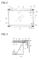
Fig. 2 is a front view of the liquid crystal module; -
Fig. 3 is an enlarged cross-sectional view taken along the line A-A inFig. 2 ; -
Fig. 4 is an enlarged cross-sectional view taken along the line B-B inFig. 2 ; -
Fig. 5 is an enlarged view of a portion of the liquid crystal module, indicated by the circle shown inFig. 2 ; -
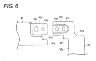
Fig. 6 is an exploded front view illustrating a connection portion between an upper-side frame member and a right-side frame member; -
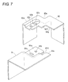
Fig. 7 is an exploded perspective view illustrating the connection portion between the upper-side frame member and a right-side frame member; -
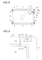
Fig. 8 is a partially-enlarged front view illustrating a liquid crystal module according to another embodiment of the present invention; and -
Fig. 9 is a partial front view illustrating a related-art liquid crystal module. - A liquid crystal module shown in
Figs. 1 to 5 includes arear frame 1, a lightreflective sheet 2, U-shapedcold cathode tubes 3, lamp holders 4,lamp frames 5,optical sheets cell guides 7, aliquid crystal panel 8, a bezel formed by connecting bezel constitutingframe members - The
rear frame 1 is a shallow box-type frame made of sheet metal. The lightreflective sheet 2 which is bent in a reversed trapezoidal shape is provided inside therear frame 1. A plurality (two in this embodiment) of U-shapedcold cathode tubes 3 are arranged in parallel with each other on the lightreflective sheet 2. U-shaped bent end portions and a center portion of thecold cathode tube 3 are held by the lamp holders 4 and are fixed to abottom plate 1b of therear frame 1. -
Lamp sockets 3a made of rubber are attached to end portions of thecold cathode tube 3 opposite to the U-shaped bent end portion. Thelamp sockets 3a are fixedly fitted into socket fitting holes (not shown) which are provided in abottom plate 1b of therear frame 1 along one of left andright side plates 1a (right side plate in this embodiment) of therear frame 1. Alead wire 3b of thecold cathode tube 3 is drawn out toward a rear side of therear frame 1. Thelamp frames 5 made of synthetic resin are attached inside left andright side plates 1a of therear frame 1. Thelamp frames 5 cover the U-shaped bent end portions and the opposite end portions which is attached to thelamp sockets 3a, of the U-shapedcold cathode tubes 3 in order to prevent variation in brightness. - As shown in
Figs. 1 and3 , each of the upper andlower side plates 1c of therear frame 1 is bent in a reversed U-shape to form double side plates, and edge portions (upper and lower edge portions) of twooptical sheets double side plates 1c and are then pressed by thecell guides 7. As shown inFig. 4 , the left and right edge portions of theoptical sheets grooves 5a of thelamp frames 5. Theoptical sheets cold cathode tubes 3 or reflected light from the lightreflective sheet 2 to uniformly irradiate the light onto theliquid crystal panel 8 from a rear side. The upperoptical sheet 6b is a thin optical diffuser sheet, and the loweroptical sheet 6a is a light diffuser sheet (light diffuser plate) having a thickness which is sufficient to resist bending. - Four edge portions of the
liquid crystal panel 8 are disposed on thelamp frames 5 and thecell guides 7. Theliquid crystal panel 8 is positioned by positioningbosses lamp frames 5 and thecell guides 7, respectively, as shown inFigs. 1 to 4 , so as not to move theliquid crystal panel 8 in upward and rearward direction and in left and right direction. As shown inFigs. 1 and3 , anX-wiring board 8b is connected to the edge portion (upper end edge) of theliquid crystal panel 8, with a chip-onfilm 8a being interposed therebetween, and theX-wiring board 8b is attached to the side surface of thecell guide 7. - Four edge portions of the
liquid crystal panel 8 are enclosed by thebezel 9 as shown inFig. 2 . Thebezel 9 includes two upper and lower long bezel constitutingframe members 91 and two left and right short bezel constitutingframe members 92 which are made of sheet metal and are connected to each other in the shape of a rectangular frame. As shown inFigs. 2 , and5 to 7 , the left and right bezel constitutingframe members 92 are provided withprotruding end portions 92a for connection. Theprotruding end portions 92a protrude inwardly at a right angle from both end portions of the left and right bezel constitutingframe members 92 and are disposed at positions outwardly offset from theliquid crystal panel 8 as viewed from above.Concave portions 92b formed in the upper surfaces of theprotruding end portions 92a are provided with apin inserting hole 92c and ascrew inserting hole 92d. - Since a recessed
portion 92e is provided in each outer corner defined between the bezel constitutingframe member 92 and theprotruding end portion 92a which protrudes at a right angle from one end portion of the bezel constitutingframe member 92, it is desirable to strengthen a neck portion of theprotruding end portion 92a. Accordingly, aconvex portion 92f is provided in each inner corner defined between the bezel constitutingframe member 92 and theprotruding end portion 92a to reinforce the neck portion. - Both end portions of the upper and lower bezel constituting
frame members 91 are provided with receivingstep portions 91a which receive theconcave portions 92b of theprotruding end portions 92a. The receivingstep portion 91a is formed such that the receivingstep portion 91a is formed lower than the other portion of the upper surface of the upper and lower bezel constitutingframe members 91. The receivingstep portions 91a are disposed at positions offset outwardly from theliquid crystal panel 8 as viewed from above. The receivingstep portion 91a is provided with apin inserting hole 91b and ascrew inserting hole 91c. Aconcave portion 91d is formed at both end portions of the bezel constitutingframe member 91 at a position other than the receivingstep portion 91a. Theconcave portion 91d corresponds to theconvex portion 92f and receives theconvex portion 92f. - The upper and lower bezel constituting
frame members 91 and the left and right bezel constitutingframe members 92 are fixedly connected to each other in the following manner. That is, theconcave portions 92b of theprotruding end portions 92a of the left and right bezel constitutingframe members 92 are overlapped with the receivingstep portions 91a of the upper and lower bezel constitutingframe members 91. Bothend surfaces 91e of the bezel constitutingframe member 91 except for the receivingstep portion 91a are adjacent to aninner end surface 92g of the bezel constitutingframe member 92, and simultaneously, theconvex portion 92f is engaged with theconcave portion 91d. Then, in a state in which thepositioning pin 7b (refer toFigs. 1 ,2 and5 ) protruding upward from thecell guide 7 is inserted into thepin inserting holes Figs. 2, 3 and5 ) is inserted into thescrew inserting holes cell guide 7, so that a screw hole (not shown) formed in the upper surface of thedouble side plates 1c of therear frame 1 is fastened to connect the bezel constitutingframe members rear frame 1. In this instance, when the bezel constitutingframe members Figs. 3 to 5 , acushion material 11 of an elongated band shape is interposed between four edge portions of theliquid crystal panel 8 and inner edge portions of the bezel constitutingframe members - As described above, four edge portions of the
liquid crystal panel 8 are enclosed by thebezel 9 including two upper and lower bezel constitutingframe members 91 and two left and right bezel constitutingframe members 92 which are connected to each other in the shape of a rectangular frame. Theprotruding end portions 92a protruding inwardly at a right angle from both end portions of the left and right bezel constitutingframe members 92 are disposed at positions outwardly offset from theliquid crystal panel 8 as viewed from above. The receivingstep portions 91a provided at both end portions of the upper and lower bezel constitutingframe members 91 are disposed at positions outwardly offset from the liquid crystal panel as viewed from above. And theprotruding end portions 92a are overlapped with the receivingstep portions 91a and then are fixed to the receivingstep portions 91a with thescrew 10. Therefore, there is no concern that the inner edge of the front end portion of theprotruding end portion 92a overlaps with and comes into contact with the edge portion of theliquid crystal panel 8. In addition, theconvex portions 92f provided at the inner corners of the left and right bezel constitutingframe members 92 and theconvex portions 91d provided at both end portions of the upper and lower bezel constitutingframe members 91 are disposed at positions outwardly offset from theliquid crystal panel 8 as viewed from above. Even in a case where the force pressing theconvex portion 92f inwardly is applied to theconvex portion 92f when theprojection end portion 92a is fixed with the screw, theconvex portion 92f does not come into contact with the edge portion of theliquid crystal panel 8. Consequently, even if a burr is produced in an end face of theprotruding end portion 92a at the time of die-cutting or the end surface of theconvex portion 92f, it is possible to solve the problem of the edge portion of theliquid crystal panel 8 being damaged by the burr. - In this instance, the
convex portion 92f for reinforcement and theconcave portion 91a corresponding to theouter corner portion 92f may be optional. -
Fig. 8 is a partially enlarged front view illustrating the liquid crystal module according to another embodiment of the invention. In thebezel 9 enclosing four edge portions of theliquid crystal panel 8, protrudingend portions 91f for connection protruding inwardly at a right angle from both end portions of the upper and lower bezel constitutingframe members 91 are disposed at positions outwardly offset from theliquid crystal panel 8 as viewed from above, and aconcave portion 91g of theprotruding end portion 91f is provided with a pin inserting hole and a screw inserting hole. Receivingstep portions 92h for receiving theprotruding end portions 91f are provided at both end portions of the left and right bezel constitutingframe members 92 and disposed at positions outwardly offset from theliquid crystal panel 8 as viewed from above. The receivingstep portions 92h are provided with a pin inserting hole and a screw inserting hole. In addition,convex portions 91h for reinforcement are provided at inner corners defined between theprotruding end portions 91f and the upper and lower bezel constitutingframe members 91. Theconvex portions 91h h are disposed at positions outwardly offset from theliquid crystal panel 8 as viewed from above.Concave portions 92i corresponding to theconvex portions 91h are provided at both end portions of the left and right bezel constitutingframe member 92 for receiving theconvex portions 91h. - The upper and lower bezel constituting
frame members 91 and the left and right bezel constitutingframe members 92 are fixedly connected to each other in the following manner. That is, theprotruding end portions 91 f for connection of the upper and lower bezel constitutingframe members 91 are overlapped with the receivingstep portions 92h of the left and right bezel constitutingframe members 92. Both end surfaces of the bezel constitutingframe member 92 except for the receivingstep portion 92h are adjacent to the inner end surface of the bezel constitutingframe member 91, and simultaneously, theconvex portion 91h is engaged with theconcave portion 92i. Then, in a state in which thepositioning pin 5c protruding upward from thelamp frame 5 is inserted into the pin inserting holes from below to position the bezel constituting frames 91 and 92, the screw 10 (refer toFigs. 2, 3 and5 ) is inserted into the screw inserting hole (or the screw hole of the rear frame) formed in the upper surface of thelamp frame 5 from the screw inserting hole. - Since other configuration of the liquid crystal module is identical to that of the above-described liquid crystal module, the description thereof will be omitted. In this instance, in the liquid crystal module, the
convex portion 91h h for reinforcement and theconcave portion 92i for receiving theconvex portion 91h may be optional. - Since the liquid crystal module is substantially identical to the above-described liquid crystal module except that the both end portions of the upper and lower bezel constituting
frame members 91 are provided with theprotruding end portions 91f for connection and both end portions of the left and right bezel constitutingframe members 92 are provided with receivingstep portions 92, and the connection and fixing configuration itself is substantially identical to the above-described liquid crystal module, the liquid crystal module in another embodiment has the same effect as that of the above-described liquid crystal module. - While the present invention has been shown and described with reference to certain exemplary embodiments thereof, it will be understood by those skilled in the art that various changes in form and details may be made therein without departing from the spirit and scope of the invention as defined by the appended claims.
Claims (4)
- A liquid crystal module, comprising:a liquid crystal panel; anda bezel including an upper frame, a lower frame, a left frame and a right frame which are connected to each other in the shape of a rectangular frame and enclosing four peripheral edges of the liquid crystal panel,wherein a protruding end portion protrudes inwardly at a right angle from each of both ends of the left and right frames and the protruding end portion is disposed at a position outwardly offset from the liquid crystal panel as viewed from above,wherein a receiving step portion which receives the protruding end portion is provided at each of both ends of the upper and lower frames and the receiving step portion is disposed at a position outwardly offset from the liquid crystal panel as viewed from above, andwherein the protruding end portion is overlapped with the receiving step portion such that both end faces of the upper and lower frames except the receiving step portion are adjacent to inner side faces of the left and right frames and the protruding end portion is fixed to the receiving step portion with a screw.
- The liquid crystal module as set forth in claim 1,
wherein a convex portion is provided at each of inner corners defined between the protruding end portion and the left and right frames and the convex portion is disposed at a position outwardly offset from the liquid crystal panel as viewed from above, and
wherein a concave portion which corresponds to the convex portion is provided at each of the both ends of the upper and lower frames and the concave portion is disposed at a position outwardly offset from the liquid crystal panel as viewed from above. - A liquid crystal module, comprising:a liquid crystal panel; anda bezel including an upper frame, a lower frame, a left frame and a right frame which are connected to each other in the shape of a rectangular frame and enclosing four peripheral edges of the liquid crystal panel,wherein a protruding end portion protrudes inwardly at a right angle from each of both ends of the left and right frames and the protruding end portion is disposed at a position outwardly offset from the liquid crystal panel as viewed from above,wherein a receiving step portion which receives the protruding end portion is provided at each of both ends of the upper and lower frames and the receiving step portion is disposed at a position outwardly offset from the liquid crystal panel as viewed from above, andwherein the protruding end portion is overlapped with the receiving step portion such that both end faces of the upper and lower frames except the receiving step portion are adjacent to inner side faces of the left and right frames and the protruding end portion is fixed to the receiving step portion with a screw.
- The liquid crystal module as set forth in claim 1,
wherein a convex portion is provided at each of inner corners defined between the protruding end portion and the left and right frames and the convex portion is disposed at a position outwardly offset from the liquid crystal panel as viewed from above, and
wherein a concave portion which corresponds to the convex portion is provided at each of the both ends of the upper and lower frames and the concave portion is disposed at a position outwardly offset from the liquid crystal panel as viewed from above.
Applications Claiming Priority (1)
| Application Number | Priority Date | Filing Date | Title |
|---|---|---|---|
| JP2009145520A JP2011002657A (en) | 2009-06-18 | 2009-06-18 | Liquid crystal module |
Publications (2)
| Publication Number | Publication Date |
|---|---|
| EP2264514A1 true EP2264514A1 (en) | 2010-12-22 |
| EP2264514B1 EP2264514B1 (en) | 2013-05-01 |
Family
ID=42813126
Family Applications (1)
| Application Number | Title | Priority Date | Filing Date |
|---|---|---|---|
| EP10165909.2A Not-in-force EP2264514B1 (en) | 2009-06-18 | 2010-06-15 | Liquid crystal module |
Country Status (3)
| Country | Link |
|---|---|
| US (1) | US20100321605A1 (en) |
| EP (1) | EP2264514B1 (en) |
| JP (1) | JP2011002657A (en) |
Cited By (2)
| Publication number | Priority date | Publication date | Assignee | Title |
|---|---|---|---|---|
| CN102566100A (en) * | 2012-02-17 | 2012-07-11 | 深圳市华星光电技术有限公司 | Front frame modularized structure and liquid crystal display device |
| EP2840434A1 (en) * | 2013-08-19 | 2015-02-25 | InnoLux Corporation | Display device |
Families Citing this family (9)
| Publication number | Priority date | Publication date | Assignee | Title |
|---|---|---|---|---|
| JP5227470B2 (en) * | 2011-10-03 | 2013-07-03 | シャープ株式会社 | Display device and television receiver |
| CN102608785B (en) * | 2012-03-30 | 2015-04-01 | 深圳市华星光电技术有限公司 | Central frame and liquid crystal display module |
| CN102692742B (en) * | 2012-06-13 | 2014-06-18 | 深圳市华星光电技术有限公司 | A liquid crystal display device |
| CN103489375B (en) * | 2013-09-30 | 2016-08-17 | 京东方科技集团股份有限公司 | A kind of display device |
| KR20150117760A (en) * | 2014-04-10 | 2015-10-21 | 삼성디스플레이 주식회사 | Display apparatus |
| JP6215867B2 (en) * | 2015-05-22 | 2017-10-18 | ミネベアミツミ株式会社 | Surface lighting device |
| CN105842892A (en) * | 2016-03-18 | 2016-08-10 | 乐视致新电子科技(天津)有限公司 | Front frame, display module and display equipment |
| WO2017156930A1 (en) * | 2016-03-18 | 2017-09-21 | 乐视控股(北京)有限公司 | Front frame, display module and display device |
| CN109656413A (en) * | 2018-12-18 | 2019-04-19 | 上海朗绿建筑科技股份有限公司 | A kind of novel touch screen all-in-one machine frame and preparation method thereof |
Citations (6)
| Publication number | Priority date | Publication date | Assignee | Title |
|---|---|---|---|---|
| US20050168954A1 (en) * | 2004-01-07 | 2005-08-04 | Yong-Il Kim | Chassis and display device having the same |
| JP2006330271A (en) | 2005-05-25 | 2006-12-07 | Sharp Corp | Method for manufacturing frame-shaped component for display device |
| JP2006350218A (en) * | 2005-06-20 | 2006-12-28 | Funai Electric Co Ltd | Liquid crystal module |
| JP2007017835A (en) | 2005-07-11 | 2007-01-25 | Funai Electric Co Ltd | Bezel and liquid crystal module having bezel |
| JP2007304279A (en) | 2006-05-10 | 2007-11-22 | Funai Electric Co Ltd | Liquid crystal display device |
| US20080297681A1 (en) * | 2007-06-01 | 2008-12-04 | Yang Yong-Seok | Top receiving container, liquid crystal display apparatus including the same, and assembly method thereof |
Family Cites Families (7)
| Publication number | Priority date | Publication date | Assignee | Title |
|---|---|---|---|---|
| TW569059B (en) * | 1999-12-09 | 2004-01-01 | Samsung Electronics Co Ltd | Liquid crystal display device |
| JP3920761B2 (en) * | 2002-11-11 | 2007-05-30 | 三洋電機株式会社 | Liquid crystal display |
| JP2008052039A (en) * | 2006-08-24 | 2008-03-06 | Hitachi Displays Ltd | Display device |
| JP2008170728A (en) * | 2007-01-11 | 2008-07-24 | Sony Corp | Backlight device and display device |
| JP5056042B2 (en) * | 2007-02-08 | 2012-10-24 | 船井電機株式会社 | Liquid crystal display |
| JP5183075B2 (en) * | 2007-02-08 | 2013-04-17 | 株式会社ジャパンディスプレイイースト | Liquid crystal display |
| KR101364652B1 (en) * | 2008-04-07 | 2014-02-19 | 엘지디스플레이 주식회사 | Method of fabricating top cover for liquid crystal display device |
-
2009
- 2009-06-18 JP JP2009145520A patent/JP2011002657A/en active Pending
-
2010
- 2010-06-14 US US12/814,752 patent/US20100321605A1/en not_active Abandoned
- 2010-06-15 EP EP10165909.2A patent/EP2264514B1/en not_active Not-in-force
Patent Citations (6)
| Publication number | Priority date | Publication date | Assignee | Title |
|---|---|---|---|---|
| US20050168954A1 (en) * | 2004-01-07 | 2005-08-04 | Yong-Il Kim | Chassis and display device having the same |
| JP2006330271A (en) | 2005-05-25 | 2006-12-07 | Sharp Corp | Method for manufacturing frame-shaped component for display device |
| JP2006350218A (en) * | 2005-06-20 | 2006-12-28 | Funai Electric Co Ltd | Liquid crystal module |
| JP2007017835A (en) | 2005-07-11 | 2007-01-25 | Funai Electric Co Ltd | Bezel and liquid crystal module having bezel |
| JP2007304279A (en) | 2006-05-10 | 2007-11-22 | Funai Electric Co Ltd | Liquid crystal display device |
| US20080297681A1 (en) * | 2007-06-01 | 2008-12-04 | Yang Yong-Seok | Top receiving container, liquid crystal display apparatus including the same, and assembly method thereof |
Cited By (3)
| Publication number | Priority date | Publication date | Assignee | Title |
|---|---|---|---|---|
| CN102566100A (en) * | 2012-02-17 | 2012-07-11 | 深圳市华星光电技术有限公司 | Front frame modularized structure and liquid crystal display device |
| WO2013120292A1 (en) * | 2012-02-17 | 2013-08-22 | 深圳市华星光电技术有限公司 | Front frame modular structure and liquid crystal display device |
| EP2840434A1 (en) * | 2013-08-19 | 2015-02-25 | InnoLux Corporation | Display device |
Also Published As
| Publication number | Publication date |
|---|---|
| JP2011002657A (en) | 2011-01-06 |
| US20100321605A1 (en) | 2010-12-23 |
| EP2264514B1 (en) | 2013-05-01 |
Similar Documents
| Publication | Publication Date | Title |
|---|---|---|
| EP2264514B1 (en) | Liquid crystal module | |
| JP4915354B2 (en) | LCD module | |
| JP5223643B2 (en) | LCD module | |
| EP2006729B1 (en) | Liquid crystal module | |
| TWI325993B (en) | Liquid crystal display device | |
| CN116583780A (en) | a display device | |
| EP2592466A1 (en) | Display device and television apparatus | |
| EP2256539A2 (en) | Liquid crystal module | |
| CN104823101A (en) | Liquid crystal display device | |
| US20030160909A1 (en) | Liquid crystal display device | |
| US8477256B2 (en) | Liquid crystal module and display device | |
| EP2006730B1 (en) | Liquid crystal display device with improved backlight assembly | |
| US7551241B2 (en) | Liquid crystal display apparatus | |
| EP2261732B1 (en) | Liquid crystal module | |
| JP2012053119A (en) | Liquid crystal module | |
| JP5050876B2 (en) | LCD module | |
| JP2009175378A (en) | Liquid crystal module | |
| JP2005077755A (en) | Frame case | |
| JP2010271662A (en) | Liquid crystal module | |
| JP2006039361A (en) | Electronic equipment and manufacturing method therefor | |
| US7845842B2 (en) | Frame member of a back lighting module | |
| JP4019381B2 (en) | Liquid crystal television and liquid crystal display device | |
| JP4534552B2 (en) | Liquid crystal display | |
| CN116027585A (en) | Liquid crystal display and backlight module and display module thereof | |
| WO2015194648A1 (en) | Chassis, backlight chassis, display device, television receiver, and method for manufacturing electronic device |
Legal Events
| Date | Code | Title | Description |
|---|---|---|---|
| PUAI | Public reference made under article 153(3) epc to a published international application that has entered the european phase |
Free format text: ORIGINAL CODE: 0009012 |
|
| AK | Designated contracting states |
Kind code of ref document: A1 Designated state(s): AL AT BE BG CH CY CZ DE DK EE ES FI FR GB GR HR HU IE IS IT LI LT LU LV MC MK MT NL NO PL PT RO SE SI SK SM TR |
|
| AX | Request for extension of the european patent |
Extension state: BA ME RS |
|
| 17P | Request for examination filed |
Effective date: 20110616 |
|
| 17Q | First examination report despatched |
Effective date: 20120201 |
|
| GRAP | Despatch of communication of intention to grant a patent |
Free format text: ORIGINAL CODE: EPIDOSNIGR1 |
|
| GRAS | Grant fee paid |
Free format text: ORIGINAL CODE: EPIDOSNIGR3 |
|
| GRAA | (expected) grant |
Free format text: ORIGINAL CODE: 0009210 |
|
| AK | Designated contracting states |
Kind code of ref document: B1 Designated state(s): AL AT BE BG CH CY CZ DE DK EE ES FI FR GB GR HR HU IE IS IT LI LT LU LV MC MK MT NL NO PL PT RO SE SI SK SM TR |
|
| REG | Reference to a national code |
Ref country code: GB Ref legal event code: FG4D |
|
| REG | Reference to a national code |
Ref country code: CH Ref legal event code: EP Ref country code: AT Ref legal event code: REF Ref document number: 610275 Country of ref document: AT Kind code of ref document: T Effective date: 20130515 |
|
| REG | Reference to a national code |
Ref country code: IE Ref legal event code: FG4D |
|
| REG | Reference to a national code |
Ref country code: DE Ref legal event code: R096 Ref document number: 602010006609 Country of ref document: DE Effective date: 20130627 |
|
| REG | Reference to a national code |
Ref country code: AT Ref legal event code: MK05 Ref document number: 610275 Country of ref document: AT Kind code of ref document: T Effective date: 20130501 |
|
| REG | Reference to a national code |
Ref country code: NL Ref legal event code: VDEP Effective date: 20130501 |
|
| REG | Reference to a national code |
Ref country code: LT Ref legal event code: MG4D |
|
| PG25 | Lapsed in a contracting state [announced via postgrant information from national office to epo] |
Ref country code: AT Free format text: LAPSE BECAUSE OF FAILURE TO SUBMIT A TRANSLATION OF THE DESCRIPTION OR TO PAY THE FEE WITHIN THE PRESCRIBED TIME-LIMIT Effective date: 20130501 Ref country code: ES Free format text: LAPSE BECAUSE OF FAILURE TO SUBMIT A TRANSLATION OF THE DESCRIPTION OR TO PAY THE FEE WITHIN THE PRESCRIBED TIME-LIMIT Effective date: 20130812 Ref country code: SE Free format text: LAPSE BECAUSE OF FAILURE TO SUBMIT A TRANSLATION OF THE DESCRIPTION OR TO PAY THE FEE WITHIN THE PRESCRIBED TIME-LIMIT Effective date: 20130501 Ref country code: GR Free format text: LAPSE BECAUSE OF FAILURE TO SUBMIT A TRANSLATION OF THE DESCRIPTION OR TO PAY THE FEE WITHIN THE PRESCRIBED TIME-LIMIT Effective date: 20130802 Ref country code: FI Free format text: LAPSE BECAUSE OF FAILURE TO SUBMIT A TRANSLATION OF THE DESCRIPTION OR TO PAY THE FEE WITHIN THE PRESCRIBED TIME-LIMIT Effective date: 20130501 Ref country code: LT Free format text: LAPSE BECAUSE OF FAILURE TO SUBMIT A TRANSLATION OF THE DESCRIPTION OR TO PAY THE FEE WITHIN THE PRESCRIBED TIME-LIMIT Effective date: 20130501 Ref country code: PT Free format text: LAPSE BECAUSE OF FAILURE TO SUBMIT A TRANSLATION OF THE DESCRIPTION OR TO PAY THE FEE WITHIN THE PRESCRIBED TIME-LIMIT Effective date: 20130902 Ref country code: NO Free format text: LAPSE BECAUSE OF FAILURE TO SUBMIT A TRANSLATION OF THE DESCRIPTION OR TO PAY THE FEE WITHIN THE PRESCRIBED TIME-LIMIT Effective date: 20130801 Ref country code: SI Free format text: LAPSE BECAUSE OF FAILURE TO SUBMIT A TRANSLATION OF THE DESCRIPTION OR TO PAY THE FEE WITHIN THE PRESCRIBED TIME-LIMIT Effective date: 20130501 Ref country code: IS Free format text: LAPSE BECAUSE OF FAILURE TO SUBMIT A TRANSLATION OF THE DESCRIPTION OR TO PAY THE FEE WITHIN THE PRESCRIBED TIME-LIMIT Effective date: 20130901 |
|
| PG25 | Lapsed in a contracting state [announced via postgrant information from national office to epo] |
Ref country code: CY Free format text: LAPSE BECAUSE OF FAILURE TO SUBMIT A TRANSLATION OF THE DESCRIPTION OR TO PAY THE FEE WITHIN THE PRESCRIBED TIME-LIMIT Effective date: 20130501 Ref country code: PL Free format text: LAPSE BECAUSE OF FAILURE TO SUBMIT A TRANSLATION OF THE DESCRIPTION OR TO PAY THE FEE WITHIN THE PRESCRIBED TIME-LIMIT Effective date: 20130501 Ref country code: BG Free format text: LAPSE BECAUSE OF FAILURE TO SUBMIT A TRANSLATION OF THE DESCRIPTION OR TO PAY THE FEE WITHIN THE PRESCRIBED TIME-LIMIT Effective date: 20130801 Ref country code: HR Free format text: LAPSE BECAUSE OF FAILURE TO SUBMIT A TRANSLATION OF THE DESCRIPTION OR TO PAY THE FEE WITHIN THE PRESCRIBED TIME-LIMIT Effective date: 20130501 |
|
| PG25 | Lapsed in a contracting state [announced via postgrant information from national office to epo] |
Ref country code: LV Free format text: LAPSE BECAUSE OF FAILURE TO SUBMIT A TRANSLATION OF THE DESCRIPTION OR TO PAY THE FEE WITHIN THE PRESCRIBED TIME-LIMIT Effective date: 20130501 |
|
| PG25 | Lapsed in a contracting state [announced via postgrant information from national office to epo] |
Ref country code: CZ Free format text: LAPSE BECAUSE OF FAILURE TO SUBMIT A TRANSLATION OF THE DESCRIPTION OR TO PAY THE FEE WITHIN THE PRESCRIBED TIME-LIMIT Effective date: 20130501 Ref country code: BE Free format text: LAPSE BECAUSE OF FAILURE TO SUBMIT A TRANSLATION OF THE DESCRIPTION OR TO PAY THE FEE WITHIN THE PRESCRIBED TIME-LIMIT Effective date: 20130501 Ref country code: SK Free format text: LAPSE BECAUSE OF FAILURE TO SUBMIT A TRANSLATION OF THE DESCRIPTION OR TO PAY THE FEE WITHIN THE PRESCRIBED TIME-LIMIT Effective date: 20130501 Ref country code: DK Free format text: LAPSE BECAUSE OF FAILURE TO SUBMIT A TRANSLATION OF THE DESCRIPTION OR TO PAY THE FEE WITHIN THE PRESCRIBED TIME-LIMIT Effective date: 20130501 Ref country code: EE Free format text: LAPSE BECAUSE OF FAILURE TO SUBMIT A TRANSLATION OF THE DESCRIPTION OR TO PAY THE FEE WITHIN THE PRESCRIBED TIME-LIMIT Effective date: 20130501 Ref country code: MC Free format text: LAPSE BECAUSE OF FAILURE TO SUBMIT A TRANSLATION OF THE DESCRIPTION OR TO PAY THE FEE WITHIN THE PRESCRIBED TIME-LIMIT Effective date: 20130501 |
|
| PG25 | Lapsed in a contracting state [announced via postgrant information from national office to epo] |
Ref country code: RO Free format text: LAPSE BECAUSE OF FAILURE TO SUBMIT A TRANSLATION OF THE DESCRIPTION OR TO PAY THE FEE WITHIN THE PRESCRIBED TIME-LIMIT Effective date: 20130501 Ref country code: NL Free format text: LAPSE BECAUSE OF FAILURE TO SUBMIT A TRANSLATION OF THE DESCRIPTION OR TO PAY THE FEE WITHIN THE PRESCRIBED TIME-LIMIT Effective date: 20130501 Ref country code: IT Free format text: LAPSE BECAUSE OF FAILURE TO SUBMIT A TRANSLATION OF THE DESCRIPTION OR TO PAY THE FEE WITHIN THE PRESCRIBED TIME-LIMIT Effective date: 20130501 |
|
| PLBE | No opposition filed within time limit |
Free format text: ORIGINAL CODE: 0009261 |
|
| STAA | Information on the status of an ep patent application or granted ep patent |
Free format text: STATUS: NO OPPOSITION FILED WITHIN TIME LIMIT |
|
| REG | Reference to a national code |
Ref country code: IE Ref legal event code: MM4A |
|
| REG | Reference to a national code |
Ref country code: DE Ref legal event code: R119 Ref document number: 602010006609 Country of ref document: DE Effective date: 20140101 |
|
| REG | Reference to a national code |
Ref country code: FR Ref legal event code: ST Effective date: 20140228 |
|
| 26N | No opposition filed |
Effective date: 20140204 |
|
| PG25 | Lapsed in a contracting state [announced via postgrant information from national office to epo] |
Ref country code: DE Free format text: LAPSE BECAUSE OF NON-PAYMENT OF DUE FEES Effective date: 20140101 Ref country code: IE Free format text: LAPSE BECAUSE OF NON-PAYMENT OF DUE FEES Effective date: 20130615 |
|
| PG25 | Lapsed in a contracting state [announced via postgrant information from national office to epo] |
Ref country code: FR Free format text: LAPSE BECAUSE OF NON-PAYMENT OF DUE FEES Effective date: 20130701 |
|
| REG | Reference to a national code |
Ref country code: CH Ref legal event code: PL |
|
| GBPC | Gb: european patent ceased through non-payment of renewal fee |
Effective date: 20140615 |
|
| PG25 | Lapsed in a contracting state [announced via postgrant information from national office to epo] |
Ref country code: MT Free format text: LAPSE BECAUSE OF FAILURE TO SUBMIT A TRANSLATION OF THE DESCRIPTION OR TO PAY THE FEE WITHIN THE PRESCRIBED TIME-LIMIT Effective date: 20130501 |
|
| PG25 | Lapsed in a contracting state [announced via postgrant information from national office to epo] |
Ref country code: CH Free format text: LAPSE BECAUSE OF NON-PAYMENT OF DUE FEES Effective date: 20140630 Ref country code: LI Free format text: LAPSE BECAUSE OF NON-PAYMENT OF DUE FEES Effective date: 20140630 |
|
| PG25 | Lapsed in a contracting state [announced via postgrant information from national office to epo] |
Ref country code: GB Free format text: LAPSE BECAUSE OF NON-PAYMENT OF DUE FEES Effective date: 20140615 Ref country code: SM Free format text: LAPSE BECAUSE OF FAILURE TO SUBMIT A TRANSLATION OF THE DESCRIPTION OR TO PAY THE FEE WITHIN THE PRESCRIBED TIME-LIMIT Effective date: 20130501 |
|
| PG25 | Lapsed in a contracting state [announced via postgrant information from national office to epo] |
Ref country code: TR Free format text: LAPSE BECAUSE OF FAILURE TO SUBMIT A TRANSLATION OF THE DESCRIPTION OR TO PAY THE FEE WITHIN THE PRESCRIBED TIME-LIMIT Effective date: 20130501 |
|
| PG25 | Lapsed in a contracting state [announced via postgrant information from national office to epo] |
Ref country code: HU Free format text: LAPSE BECAUSE OF FAILURE TO SUBMIT A TRANSLATION OF THE DESCRIPTION OR TO PAY THE FEE WITHIN THE PRESCRIBED TIME-LIMIT; INVALID AB INITIO Effective date: 20100615 Ref country code: MK Free format text: LAPSE BECAUSE OF FAILURE TO SUBMIT A TRANSLATION OF THE DESCRIPTION OR TO PAY THE FEE WITHIN THE PRESCRIBED TIME-LIMIT Effective date: 20130501 Ref country code: LU Free format text: LAPSE BECAUSE OF NON-PAYMENT OF DUE FEES Effective date: 20130615 |
|
| PG25 | Lapsed in a contracting state [announced via postgrant information from national office to epo] |
Ref country code: AL Free format text: LAPSE BECAUSE OF FAILURE TO SUBMIT A TRANSLATION OF THE DESCRIPTION OR TO PAY THE FEE WITHIN THE PRESCRIBED TIME-LIMIT Effective date: 20130501 |