EP2264497A1 - Fiber optic module assembly having improved finger access and labeling indicia - Google Patents
Fiber optic module assembly having improved finger access and labeling indicia Download PDFInfo
- Publication number
- EP2264497A1 EP2264497A1 EP10006046A EP10006046A EP2264497A1 EP 2264497 A1 EP2264497 A1 EP 2264497A1 EP 10006046 A EP10006046 A EP 10006046A EP 10006046 A EP10006046 A EP 10006046A EP 2264497 A1 EP2264497 A1 EP 2264497A1
- Authority
- EP
- European Patent Office
- Prior art keywords
- connector
- fiber optic
- adapter
- module assembly
- adapters
- Prior art date
- Legal status (The legal status is an assumption and is not a legal conclusion. Google has not performed a legal analysis and makes no representation as to the accuracy of the status listed.)
- Withdrawn
Links
- 239000000835 fiber Substances 0.000 title claims abstract description 94
- 238000002372 labelling Methods 0.000 title claims abstract description 29
- 230000003287 optical effect Effects 0.000 claims abstract description 51
- 239000013307 optical fiber Substances 0.000 claims description 9
- 238000003491 array Methods 0.000 description 4
- 238000004891 communication Methods 0.000 description 2
- 238000013461 design Methods 0.000 description 2
- 238000009434 installation Methods 0.000 description 2
- 241000220317 Rosa Species 0.000 description 1
- 238000013459 approach Methods 0.000 description 1
- 230000000712 assembly Effects 0.000 description 1
- 238000000429 assembly Methods 0.000 description 1
- 230000009286 beneficial effect Effects 0.000 description 1
- 239000003086 colorant Substances 0.000 description 1
- 238000011161 development Methods 0.000 description 1
- 238000003780 insertion Methods 0.000 description 1
- 230000037431 insertion Effects 0.000 description 1
- 230000014759 maintenance of location Effects 0.000 description 1
- 230000013011 mating Effects 0.000 description 1
- 238000000034 method Methods 0.000 description 1
- 238000007649 pad printing Methods 0.000 description 1
- 239000007787 solid Substances 0.000 description 1
- 230000000007 visual effect Effects 0.000 description 1
Images






Classifications
-
- G—PHYSICS
- G02—OPTICS
- G02B—OPTICAL ELEMENTS, SYSTEMS OR APPARATUS
- G02B6/00—Light guides; Structural details of arrangements comprising light guides and other optical elements, e.g. couplings
- G02B6/44—Mechanical structures for providing tensile strength and external protection for fibres, e.g. optical transmission cables
- G02B6/4439—Auxiliary devices
- G02B6/444—Systems or boxes with surplus lengths
- G02B6/4452—Distribution frames
- G02B6/44526—Panels or rackmounts covering a whole width of the frame or rack
-
- G—PHYSICS
- G02—OPTICS
- G02B—OPTICAL ELEMENTS, SYSTEMS OR APPARATUS
- G02B6/00—Light guides; Structural details of arrangements comprising light guides and other optical elements, e.g. couplings
- G02B6/24—Coupling light guides
- G02B6/36—Mechanical coupling means
- G02B6/38—Mechanical coupling means having fibre to fibre mating means
- G02B6/3807—Dismountable connectors, i.e. comprising plugs
- G02B6/381—Dismountable connectors, i.e. comprising plugs of the ferrule type, e.g. fibre ends embedded in ferrules, connecting a pair of fibres
- G02B6/3825—Dismountable connectors, i.e. comprising plugs of the ferrule type, e.g. fibre ends embedded in ferrules, connecting a pair of fibres with an intermediate part, e.g. adapter, receptacle, linking two plugs
-
- G—PHYSICS
- G02—OPTICS
- G02B—OPTICAL ELEMENTS, SYSTEMS OR APPARATUS
- G02B6/00—Light guides; Structural details of arrangements comprising light guides and other optical elements, e.g. couplings
- G02B6/44—Mechanical structures for providing tensile strength and external protection for fibres, e.g. optical transmission cables
- G02B6/4439—Auxiliary devices
- G02B6/444—Systems or boxes with surplus lengths
- G02B6/44528—Patch-cords; Connector arrangements in the system or in the box
Definitions
- the disclosure relates generally to a fiber optic module assembly having improved finger access, and specifically to a high density fiber optic module assembly having shuttered adapters with improved finger access with port and optical channel labeling indicia, including a labeling key.
- a rack mounted 4U shelf can accommodate up to 12 vertically oriented sub-panels, referred to hereinafter as fiber optic modules, each able to carry up to 24 individual optical channels, or 12 optical ports (two optical channels per port).
- the 12 port fiber optic module comprised 12 distinct, longitudinally oriented adapter apertures, each with its own adapter, usually the LC duplex adapter. This proves challenging in terms of finger access as such an arrangement requires the apertures, and the adapters, to reside closely together due to size constraints of the module housing.
- a high density fiber optic module solution is needed that improves finger access to the connectors in the adapter arrays and provides pre-printed labeling of both the ports and the optical channels.
- the disclosure relates generally to a fiber optic module assembly and specifically to a high density fiber optic module assembly with improved finger access and labeling indicia.
- the module assembly of the disclosure has front adapter apertures commonly defining two distinct port locations including the labeling indicia for the port locations and for the optical channels associated with each port location, and a labeling key.
- the assembly comprises a plurality of first connector adapters, a plurality of second connector adapters, a fiber optic module housing and at least one fiber optic harness.
- the first connector adapters and the second connector adapters are duplex adapters able to receive and optically mate two pairs of single fiber optical connectors, such as LC connectors.
- the fiber optic module housing has a front surface and a back surface, the front surface defining a plurality of front adapter apertures, wherein a first connector adapter and a second adapter aperture are received by a common front adapter aperture.
- the first connector adapter defines a first port and the second connector adapter defines a second port.
- each front adapter aperture defines two distinct port locations and has indicia to identify the respective port locations.
- the duplex adapters define two receptacles capable of receiving and optically mating two pairs of single fiber optical connectors.
- Each mated pair of single fiber optical connectors defines an optical channel, wherein a pair of optical channels defines a port, the port having one optical input channel and one optical output channel.
- the front adapter aperture respectively receiving a first connector adapter and a second connector adapter, has indicia to label each port location and each respective optical channel pair for each port location.
- the fiber optic harness comprises at least a first connector, a second connector, a third connector and optical fibers, wherein the first and second connectors are optically interconnected to the third connector by the optical fibers.
- the fiber optic harness preferably comprises a plurality of first and second connectors being optically interconnected to a third connector, wherein first and second connectors are LC connectors and the third connector is a multi-fiber optical connector such as a MTP or MPO connector, and is housed in the interior space partially defined by the front surface and the back surface.
- the fiber optic harness is preferably a universal wired fiber optic harness, though other wiring schemes may be used.
- the fiber optic module housing further has at least one back adapter aperture defined by the back surface, wherein the third connector is received by a third connector adapter received by the at least one back adapter aperture.
- Fig. 1 shows a fiber optic module assembly as known in the art
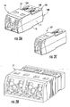
- Figs. 2A-2C show embodiments of adapters of the disclosure
- Figs. 3A and 3B show two views of the fiber optic module housing and duplex adapters of the disclosure
- Fig. 4 shows the improved finger access of the module assembly of the disclosure
- Fig. 5 shows the relationship of dimensions of the shuttered duplex adapter and the front adapter aperture
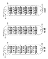
- Figs. 6A-C show a front view of various embodiments of the module of the disclosure
- Fig. 7A shows a labeling scheme found in prior art
- Figs. 7B-D show labeling embodiments of the disclosure
- Fig. 8 shows a partially exploded view of the fiber optic module assembly of the disclosure
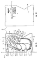
- Fig. 9A and 9B shows a fiber optic module assembly of the disclosure with the lid removed and fiber wiring revealed
- Fig. 10 shows a schematic representation of the universal wiring used in the disclosure.
- Fig. 1 shows a fiber optic module assembly as known in the prior art.
- Said assembly has twelve fiber optic adapters situated individually and in a longitudinal orientation in a 2 x 6 array. In such a module, if fully populated by patch cables (not shown), the craft must engage the crowded module face to remove or replace a duplex connector, which in the past presented tactile issues with hand accessibility and visual issues by obscuring labeling indicia.
- Fiber optic modules found in the art utilized this adapter array to accommodate the duplex adapter design as found in the prior art, such designs having retaining clips and flanges oriented on either side of the adapter body along side the connector receptacles.
- the adapters in the art were unable to reside horizontally in a common aperture, which is a much more natural orientation.
- the improved orientation as seen in the disclosure improves finger access without sacrificing port density and greatly improves visibility of the necessary labeling indicia.
- the fiber optic module assembly of the disclosure has a first connector adapter and a second connector adapter, wherein the first and second connector adapters are duplex connector adapters, preferably LC shuttered duplex adapters as disclosed in U.S Pat. Ser. No. 12/231,144 filed August 29, 2008 to Corning Cable Systems LLC.
- the shuttered duplex adapter 10 as disclosed in the '144 filing provides improved geometry that facilitates installation into a fiber optic module housing that allows alternative orientation and improves finger access.
- the shuttered duplex adapter 10 has smooth side wall 11 on each side rather than side flanges.
- FIG. 2B shows shuttered quad adapter 10' of the '144 filing that functions the same as two shuttered duplex adapters 10, forming another embodiment of a I x 4 connector receptacle array (one 1 x 4 adapter).
- FIG. 2C shows shuttered simplex adapter 10", made in the same manner as shuttered duplex adapter 10, suitable for inserting into a common front adapter aperture (see Fig. 6C ) with three other shuttered simplex adapters 10" to form another embodiment of a 1 x 4 connector receptacle array (four 1 x 1 adapters) .
- two shuttered simplex adapters 10" may be combined in a common aperture with shuttered duplex adapter 10 to form yet another embodiment of a 1 x 4 connector receptacle array (two 1 x 1 adapters and one 1 x 2 adapter).
- Figs. 3A and 3B show fiber optic module housing 20 having a plurality of shuttered duplex adapters 10.
- Fiber optic module housing 20 has latch apertures 21A and 21B defining a longitudinal axis, wherein the plurality of shuttered duplex adapters 10 are in perpendicular arrays relative to said longitudinal axis.
- the smooth side wall 11 on each side of the shuttered duplex adapter 10 enables two adapters to be received in a common aperture 20A defined by front surface 22 (see Fig. 5 ).
- This orientation allows fiber optic module housing 20 to have the same footprint of-the prior art fiber optic module assembly seen in Fig. 1 but with at least 30% more spacing between adjacent adapter arrays.
- adapter array spacing 23 between adjacent adapter arrays in a preferred embodiment of the disclosure is about 8 mm or greater. This greatly improves finger access, allowing easier hand installation of duplex connector 24.
- Fig. 5 shows front adapter apertures, 20A, found on front surface 22 of fiber optic module housing 20.
- Fiber optic module housing 20 preferably has six front adapter apertures 20A-F, each with the same proportional relationship with the shuttered duplex adapter 10, permitting six common pairings of twelve shuttered duplex adapters 10.
- Figs. 6A-C reiterates the various embodiments of the improved finger access by way of perpendicular orientation of the disclosure above.
- Fig. 6A shows six shuttered quad adapters 10' within six front adapter apertures 20A-F.
- Fig. 6B shows twelve shuttered duplex adapters 10, two each respectively in each of the six front adapter apertures 20A-F.
- Fig. 6C shows twenty-four shuttered simplex adapters 10", four each respectively in the six front adapter apertures 20A-F.
- the labeling indicia of the disclosure include port labels and the optical channels labels associated with each respective port. This provides a convenience for the craft, wherein some of whom may prefer labeling at the port level, some of whom at the optical channel (fiber) level.
- the sub-panel level it is beneficial to include both labeling schemes relative to the port locations and format them in a manner that meets guidelines set by the Telecommunications Industry Association (TIA) in their document TIA-606-A-1, Administration Standard for Commercial Telecommunications Infrastructure Addendum 1, Administration of Equipment Rooms and Data Center Computer Rooms.
- TIA Telecommunications Industry Association
- the fiber optic module assemblies of the disclosure may be grouped together in a single rack mounted shelf and tracked as "sub-panels.” Typically, each subpanel is designated by a label as a discrete unit within the shelf.
- the shelf is given its own designation relative to its height, in "rack units" (U) from the floor, while the racks (not shown) are mapped on a grid.
- labeling implies either the individual ports, meaning a pair of input/output optical channels, or the input/output optical channels themselves. As seen in the disclosure, it is advantageous to provide both labeling schemes.
- Fig. 7A shows the labeling indicia of the prior art of Fig. 1 , which has only the optical input/output channels labeled top to bottom then left to right when in the vertical orientation.
- Figs. 7B-D show the various labeling indicia embodiments of the disclosure, though it is understood that other embodiments may be possible and the disclosure is in no way limited to the embodiments illustrated herein.
- Fig. 7B shows port labels 31 using Arabic numerals beginning with the numeral "1" for port number one on the left of the top front adapter aperture 20A.
- Each front adapter aperture 20B-F has a subsequent Arabic numeral on the left side of the aperture, ending in numeral "6" for port six.
- the port numbering scheme resumes on the top, right side of the front adapter apertures, beginning again with front adapter aperture 20A labeled with the numeral "7” for port number seven This continues as on the left side, down the front surface until front adapter aperture 20F has the numerals "12" for port number twelve on its right side.
- Front surface 22 further has pairs of Arabic numerical values above each aperture and on substantially the left side, correlating left side optical input/output channel labels 33 with the left side port locations.
- Optical input/output channels for port number one have Arabic numerical values "1-2", indicating optical channels one and two that are affiliated with port number one.
- Each left side port location has its optical input/output channels labeled in sequence, having in turn subsequent pairs of Arabic numerical values on substantially the left side and above the front adapter apertures until port number six has its labels "11-12".
- the labeling of the right side (lower) optical input/output channels 35 resumes on the right side.
- the Arabic numerical values are located below each respective front adapter aperture for ports seven through twelve.
- Indicia found on Fig. 7B are solid white font without serifs on a dark housing background.
- Indicia include a decorative partial border 37, 38 that starts at an imaginary dividing plane and sweeps up or down and above or below, respectively, until the border reaches the opposing outer planes of the adjacent adapters.
- Fig. 7C is another embodiment, similar to Fig. 7B , but with indicia above the front adapter apertures on both the left and right of the imaginary dividing plane.
- the left side seen in the embodiment of Fig. 7C is identical to the embodiment seen in Fig. 7B .
- Port labels 31 on the left and right sides are in the same relative position as in Fig. 7B .
- the right side has optical input/output channel indicia above the respective port location rather than below.
- Left side (upper) optical input/output channel labels 33' are above the respective port location along with partial border (upper) 39.
- Fig. 7D has optical input/output channel tabbed indicia 40, above the front adapter apertures 20A-F on both the right and left. Port labels 31 are as seen in the previous embodiments.
- Optical input/output channel tabbed indicia 40 is an applied white tab having the Arabic numeral channel indicia 41 as a "negative" image 42 in the white tab of the optical input/output channel tabbed indicia 40.
- the disclosure provides an informational labeling key 45 located on removable lid 47 as seen in Figs. 8 and 9A-B , though other locations are possible.
- the optical input/output channel labels are indicated by the label “FIBER LABELS” and the port labels indicated by the label "PORT LABEL,” adjacent to a stylized image of the front of a two channel port. All labeling key indicia are in the relative positions as is seen in the various embodiments, though other relative positions may convey the same information.
- Fiber optic module assembly 50 comprises at least one first connector 53 and preferably a plurality of first connectors 53, such as an LC, SC or similar single fiber connector, that engages shuttered duplex adapter 10; optical wave guides 58, preferably wherein a fiber optic ribbon 54 breaks out via furcation 56 into individual optical fibers 52; and a third connector 57, preferably a multi-fiber connector such as an MTP or MPO connector.
- the plurality of first connectors 53 are in optical communication with the third connector 57 via the optical wave guides 58.
- Third connector 57 is received by third connector adapter 51 on back surface 59 of fiber optic module housing 20.
- Shuttered duplex adapter 10 is received through one of front adapter apertures 20A-F defined by front surface 22.
- Fiber optic harness A and B have their respective ports and optical channels identified.
- Fiber optic harness A and B are housed within an interior portion of fiber optic module housing 20 partially defined by front surface 22 and back surface 59.
- Fiber optic harness A is "above" fiber optic harness B.
- Fiber optic harness A provides the optical interface for the left side of the fiber optic module assembly of the disclosure, while fiber optic harness B provides the optical interface for the right side of the fiber optic module assembly of the disclosure.
- Both fiber optic harnesses A and B are preferably universal wired harnesses, discussed in more detail below.
- the fiber optic harness of the disclosure may be wired in any configuration as deemed necessary by the craft, but is preferably a universal wired harness.
- the universal wiring of the fiber optic harness of the above disclosure will now be described in detail by incorporating in part U.S. Pat. Ser. No. 10/256,799 , namely column 3, lines 6-31, filed Sep. 27, 2002 to Coming Cable Systems, LLC.
- Fig. 10 illustrates an exemplary fiber wiring scheme for routing of optical fibers from connector 140 to single or multi-fiber connectors located at connector stations 151-156, defined at a break-out section 150 of module 160.
- Each connector station 151-156 preferably includes one or more connectors.
- an exemplary routing scheme is the following: fiber number 1 (blue) is paired with fiber number 12 (aqua); fiber number 2 (orange) is paired with fiber number 11 (rose); fiber number 3 (green) is paired with fiber number 10 (violet); through the remaining numbers/colors of fiber with the last pair being fiber number 6 (white) with fiber number 7 (red).
- the fiber pairs are defined as follows: 121-132; 122-131; 123-130; 124-129; 125-128; and 126-127.
- At least one but preferably at least 80% of the fiber pairs routed to respective connector stations 151-156 are made by fibers not immediately adjacent in the optical fiber ribbon 120.
- the optical paths of connector 140 and the optical connectors at stations 151- 156 are optically interconnected by optical fibers disposed in cavity 162 of the module 160, the fiber pairs being formed by the optical fibers.
- At least one of the fiber pairs being in optical communication with respective optical paths in connector 140 and being routed to a respective connector station, the at least two optical paths being selected from optical paths not being immediately adjacent to each other.
Landscapes
- Physics & Mathematics (AREA)
- General Physics & Mathematics (AREA)
- Optics & Photonics (AREA)
- Light Guides In General And Applications Therefor (AREA)
Abstract
A fiber optic module assembly is disclosed herein having improved finger access, the module assembly of the disclosure also having pairs of adapters received in common adapter apertures (20A) perpendicular to a longitudinal axis for improved finger access. The fiber optic module assembly of the disclosure, the housing further having labeling indicia relating to port locations and optical input/output channels associated with the port locations, and the assembly also including a universal wired fiber optic harness (55).
Description
- The disclosure relates generally to a fiber optic module assembly having improved finger access, and specifically to a high density fiber optic module assembly having shuttered adapters with improved finger access with port and optical channel labeling indicia, including a labeling key.
- The ever increasing need for more capacity drives the development of high density data center solutions. Current practice in telecommunications is to utilize standard electronics racks or frames that support standards-sized stationary rack-mounted housings with widths of 19 or 23 inches horizontal spacing. Vertical spacing has been divided into rack units "U", where IU=1.75 inches as specified in EIA (Electronic Industries Alliance) 310-D, IEC (International Electrotechnical Commission) 60297 and DIN ("German Institute for Standardization") 41494 SC48D. A rack mounted 4U shelf can accommodate up to 12 vertically oriented sub-panels, referred to hereinafter as fiber optic modules, each able to carry up to 24 individual optical channels, or 12 optical ports (two optical channels per port). In the past the 12 port fiber optic module comprised 12 distinct, longitudinally oriented adapter apertures, each with its own adapter, usually the LC duplex adapter. This proves challenging in terms of finger access as such an arrangement requires the apertures, and the adapters, to reside closely together due to size constraints of the module housing.
- Other industry standards, such as TIA-606-A, Addendum 1, provide parameters for data center administration. As data centers get more crowded, tracking the fibers, ports, sub-panels, panels and floor space becomes more challenging and requires a methodical approach. Labeling starts with the floor grid coordinates to establish the geographic location of a rack of hardware. It then moves to the vertical location of the rack itself, specifically the "U" location of the top of the hardware in the rack from the floor up. Then each piece of rack mounted hardware is divided into panels or sub-panels, as many as 12 sub-panels in a 4U sized patch panel. Each sub-pancl, or fiber optic module, is typically labeled according to the number of ports it contains. Sometimes, with each port comprising two optical channels, the optical channels are labeled rather than the ports.
- A high density fiber optic module solution is needed that improves finger access to the connectors in the adapter arrays and provides pre-printed labeling of both the ports and the optical channels.
- The disclosure relates generally to a fiber optic module assembly and specifically to a high density fiber optic module assembly with improved finger access and labeling indicia. The module assembly of the disclosure has front adapter apertures commonly defining two distinct port locations including the labeling indicia for the port locations and for the optical channels associated with each port location, and a labeling key. The assembly comprises a plurality of first connector adapters, a plurality of second connector adapters, a fiber optic module housing and at least one fiber optic harness. The first connector adapters and the second connector adapters are duplex adapters able to receive and optically mate two pairs of single fiber optical connectors, such as LC connectors. The fiber optic module housing has a front surface and a back surface, the front surface defining a plurality of front adapter apertures, wherein a first connector adapter and a second adapter aperture are received by a common front adapter aperture. The first connector adapter defines a first port and the second connector adapter defines a second port. Thus, each front adapter aperture defines two distinct port locations and has indicia to identify the respective port locations.
- The duplex adapters define two receptacles capable of receiving and optically mating two pairs of single fiber optical connectors. Each mated pair of single fiber optical connectors defines an optical channel, wherein a pair of optical channels defines a port, the port having one optical input channel and one optical output channel. The front adapter aperture, respectively receiving a first connector adapter and a second connector adapter, has indicia to label each port location and each respective optical channel pair for each port location.
- The fiber optic harness comprises at least a first connector, a second connector, a third connector and optical fibers, wherein the first and second connectors are optically interconnected to the third connector by the optical fibers. The fiber optic harness preferably comprises a plurality of first and second connectors being optically interconnected to a third connector, wherein first and second connectors are LC connectors and the third connector is a multi-fiber optical connector such as a MTP or MPO connector, and is housed in the interior space partially defined by the front surface and the back surface. The fiber optic harness is preferably a universal wired fiber optic harness, though other wiring schemes may be used. The fiber optic module housing further has at least one back adapter aperture defined by the back surface, wherein the third connector is received by a third connector adapter received by the at least one back adapter aperture.
- Embodiments of the disclosure are illustrated by the accompanying drawings, in which:
-
Fig. 1 shows a fiber optic module assembly as known in the art; -
Figs. 2A-2C show embodiments of adapters of the disclosure; -
Figs. 3A and 3B show two views of the fiber optic module housing and duplex adapters of the disclosure; -
Fig. 4 shows the improved finger access of the module assembly of the disclosure; -
Fig. 5 shows the relationship of dimensions of the shuttered duplex adapter and the front adapter aperture; -
Figs. 6A-C show a front view of various embodiments of the module of the disclosure; -
Fig. 7A shows a labeling scheme found in prior art, andFigs. 7B-D show labeling embodiments of the disclosure; -
Fig. 8 shows a partially exploded view of the fiber optic module assembly of the disclosure; -
Fig. 9A and 9B shows a fiber optic module assembly of the disclosure with the lid removed and fiber wiring revealed; and -
Fig. 10 shows a schematic representation of the universal wiring used in the disclosure. - The disclosure relates generally to a fiber optic module assembly and specifically to a high density fiber optic module assembly with improved finger access and improved labeling indicia over the prior art.
Fig. 1 shows a fiber optic module assembly as known in the prior art. Said assembly has twelve fiber optic adapters situated individually and in a longitudinal orientation in a 2 x 6 array. In such a module, if fully populated by patch cables (not shown), the craft must engage the crowded module face to remove or replace a duplex connector, which in the past presented tactile issues with hand accessibility and visual issues by obscuring labeling indicia. Fiber optic modules found in the art utilized this adapter array to accommodate the duplex adapter design as found in the prior art, such designs having retaining clips and flanges oriented on either side of the adapter body along side the connector receptacles. The adapters in the art were unable to reside horizontally in a common aperture, which is a much more natural orientation. The improved orientation as seen in the disclosure improves finger access without sacrificing port density and greatly improves visibility of the necessary labeling indicia. - The fiber optic module assembly of the disclosure has a first connector adapter and a second connector adapter, wherein the first and second connector adapters are duplex connector adapters, preferably LC shuttered duplex adapters as disclosed in
U.S Pat. Ser. No. 12/231,144 filed August 29, 2008 Fig. 2A , theshuttered duplex adapter 10 as disclosed in the '144 filing provides improved geometry that facilitates installation into a fiber optic module housing that allows alternative orientation and improves finger access. The shutteredduplex adapter 10 hassmooth side wall 11 on each side rather than side flanges. Upper andlower flanges latches 14A-D to lock the shutteredduplex adapter 10 to a planar surface through an aperture. As seen in the '144 filing, orienting the retention features (12, 13 and 14A-D) of the improved shutteredduplex adapter 10 above and below the connector receptacles allows two shutteredduplex adapters 10 to reside within a common aperture, forming a 1 x 4 connector receptacle array (two 1 x 2 adapters).Fig. 2B shows shuttered quad adapter 10' of the '144 filing that functions the same as two shutteredduplex adapters 10, forming another embodiment of a I x 4 connector receptacle array (one 1 x 4 adapter).Fig. 2C shows shutteredsimplex adapter 10", made in the same manner as shutteredduplex adapter 10, suitable for inserting into a common front adapter aperture (seeFig. 6C ) with three other shutteredsimplex adapters 10" to form another embodiment of a 1 x 4 connector receptacle array (four 1 x 1 adapters) . In another embodiment (not shown) two shutteredsimplex adapters 10" may be combined in a common aperture with shutteredduplex adapter 10 to form yet another embodiment of a 1 x 4 connector receptacle array (two 1 x 1 adapters and one 1 x 2 adapter). -
Figs. 3A and 3B show fiberoptic module housing 20 having a plurality of shutteredduplex adapters 10. Fiberoptic module housing 20 haslatch apertures duplex adapters 10 are in perpendicular arrays relative to said longitudinal axis. Thesmooth side wall 11 on each side of the shutteredduplex adapter 10 enables two adapters to be received in acommon aperture 20A defined by front surface 22 (seeFig. 5 ). This orientation allows fiberoptic module housing 20 to have the same footprint of-the prior art fiber optic module assembly seen inFig. 1 but with at least 30% more spacing between adjacent adapter arrays. As seen inFig. 4 , adapter array spacing 23 between adjacent adapter arrays in a preferred embodiment of the disclosure is about 8 mm or greater. This greatly improves finger access, allowing easier hand installation ofduplex connector 24. -
Fig. 5 shows front adapter apertures, 20A, found onfront surface 22 of fiberoptic module housing 20. The relationship of width dimension X and height dimension Y offront adapter aperture 20A to dimensions 15-17 of shutteredduplex adapter 10, wherein dimension a is the height of insert portion 18 (15), dimension b is the width of shuttered duplex adapter 10 (16) and c is the height of external portion 19 (17), is as follows:



Further, dimension a relates to dimension c as follows:
- These proportions permit the insertion of two shuttered
duplex adapters 10 into a commonfront adapter aperture 20A. Fiberoptic module housing 20 preferably has sixfront adapter apertures 20A-F, each with the same proportional relationship with the shutteredduplex adapter 10, permitting six common pairings of twelve shutteredduplex adapters 10. -
Figs. 6A-C reiterates the various embodiments of the improved finger access by way of perpendicular orientation of the disclosure above.Fig. 6A shows six shuttered quad adapters 10' within sixfront adapter apertures 20A-F.Fig. 6B shows twelve shutteredduplex adapters 10, two each respectively in each of the sixfront adapter apertures 20A-F.Fig. 6C shows twenty-four shutteredsimplex adapters 10", four each respectively in the sixfront adapter apertures 20A-F. - The labeling indicia of the disclosure include port labels and the optical channels labels associated with each respective port. This provides a convenience for the craft, wherein some of whom may prefer labeling at the port level, some of whom at the optical channel (fiber) level. At the sub-panel level it is beneficial to include both labeling schemes relative to the port locations and format them in a manner that meets guidelines set by the Telecommunications Industry Association (TIA) in their document TIA-606-A-1, Administration Standard for Commercial
Telecommunications Infrastructure Addendum 1, Administration of Equipment Rooms and Data Center Computer Rooms. The fiber optic module assemblies of the disclosure may be grouped together in a single rack mounted shelf and tracked as "sub-panels." Typically, each subpanel is designated by a label as a discrete unit within the shelf. The shelf is given its own designation relative to its height, in "rack units" (U) from the floor, while the racks (not shown) are mapped on a grid. At the sub-panel level, labeling implies either the individual ports, meaning a pair of input/output optical channels, or the input/output optical channels themselves. As seen in the disclosure, it is advantageous to provide both labeling schemes. - The labels themselves are installed using a pad printing process well known in the art, whereby ink is applied to a 3-dimensional object. A simple font such as Arial that does not include serifs is required by the TIA standard.
Fig. 7A shows the labeling indicia of the prior art ofFig. 1 , which has only the optical input/output channels labeled top to bottom then left to right when in the vertical orientation.Figs. 7B-D show the various labeling indicia embodiments of the disclosure, though it is understood that other embodiments may be possible and the disclosure is in no way limited to the embodiments illustrated herein.Fig. 7B shows port labels 31 using Arabic numerals beginning with the numeral "1" for port number one on the left of the topfront adapter aperture 20A. Eachfront adapter aperture 20B-F has a subsequent Arabic numeral on the left side of the aperture, ending in numeral "6" for port six. The port numbering scheme resumes on the top, right side of the front adapter apertures, beginning again withfront adapter aperture 20A labeled with the numeral "7" for port number seven This continues as on the left side, down the front surface untilfront adapter aperture 20F has the numerals "12" for port number twelve on its right side. -
Front surface 22 further has pairs of Arabic numerical values above each aperture and on substantially the left side, correlating left side optical input/output channel labels 33 with the left side port locations. Optical input/output channels for port number one have Arabic numerical values "1-2", indicating optical channels one and two that are affiliated with port number one. Each left side port location has its optical input/output channels labeled in sequence, having in turn subsequent pairs of Arabic numerical values on substantially the left side and above the front adapter apertures until port number six has its labels "11-12". The labeling of the right side (lower) optical input/output channels 35 resumes on the right side. However, the Arabic numerical values are located below each respective front adapter aperture for ports seven through twelve. - Indicia found on
Fig. 7B are solid white font without serifs on a dark housing background. Indicia include a decorativepartial border -
Fig. 7C is another embodiment, similar toFig. 7B , but with indicia above the front adapter apertures on both the left and right of the imaginary dividing plane. The left side seen in the embodiment ofFig. 7C is identical to the embodiment seen inFig. 7B . Port labels 31 on the left and right sides are in the same relative position as inFig. 7B . The right side, however, has optical input/output channel indicia above the respective port location rather than below. Left side (upper) optical input/output channel labels 33' are above the respective port location along with partial border (upper) 39. -
Fig. 7D has optical input/output channel tabbedindicia 40, above thefront adapter apertures 20A-F on both the right and left. Port labels 31 are as seen in the previous embodiments. Optical input/output channel tabbedindicia 40 is an applied white tab having the Arabic numeral channel indicia 41 as a "negative"image 42 in the white tab of the optical input/output channel tabbedindicia 40. - In addition to the labeling indicia in
Fig. 7B-D , the disclosure provides aninformational labeling key 45 located onremovable lid 47 as seen inFigs. 8 and9A-B , though other locations are possible. The optical input/output channel labels are indicated by the label "FIBER LABELS" and the port labels indicated by the label "PORT LABEL," adjacent to a stylized image of the front of a two channel port. All labeling key indicia are in the relative positions as is seen in the various embodiments, though other relative positions may convey the same information. -
Figs. 8 and9A-B show a partially exploded view of fiberoptic module assembly 50, further includingfiber optic harness 55. Fiberoptic module assembly 50 comprises at least onefirst connector 53 and preferably a plurality offirst connectors 53, such as an LC, SC or similar single fiber connector, that engages shutteredduplex adapter 10; optical wave guides 58, preferably wherein afiber optic ribbon 54 breaks out viafurcation 56 into individualoptical fibers 52; and athird connector 57, preferably a multi-fiber connector such as an MTP or MPO connector. The plurality offirst connectors 53 are in optical communication with thethird connector 57 via the optical wave guides 58.Third connector 57 is received bythird connector adapter 51 onback surface 59 of fiberoptic module housing 20.Shuttered duplex adapter 10 is received through one offront adapter apertures 20A-F defined byfront surface 22.
- Referring to Table 1, two fiber optic harnesses A and B have their respective ports and optical channels identified. Fiber optic harness A and B are housed within an interior portion of fiber
optic module housing 20 partially defined byfront surface 22 and backsurface 59. Fiber optic harness A is "above" fiber optic harness B. Fiber optic harness A provides the optical interface for the left side of the fiber optic module assembly of the disclosure, while fiber optic harness B provides the optical interface for the right side of the fiber optic module assembly of the disclosure. Both fiber optic harnesses A and B are preferably universal wired harnesses, discussed in more detail below. - The fiber optic harness of the disclosure may be wired in any configuration as deemed necessary by the craft, but is preferably a universal wired harness. The universal wiring of the fiber optic harness of the above disclosure will now be described in detail by incorporating in part
U.S. Pat. Ser. No. 10/256,799 column 3, lines 6-31, filed Sep. 27, 2002 to Coming Cable Systems, LLC. -
Fig. 10 illustrates an exemplary fiber wiring scheme for routing of optical fibers fromconnector 140 to single or multi-fiber connectors located at connector stations 151-156, defined at a break-outsection 150 ofmodule 160. Each connector station 151-156 preferably includes one or more connectors. In the module, an exemplary routing scheme is the following: fiber number 1 (blue) is paired with fiber number 12 (aqua); fiber number 2 (orange) is paired with fiber number 11 (rose); fiber number 3 (green) is paired with fiber number 10 (violet); through the remaining numbers/colors of fiber with the last pair being fiber number 6 (white) with fiber number 7 (red). With reference toFig. 10 , the fiber pairs are defined as follows: 121-132; 122-131; 123-130; 124-129; 125-128; and 126-127. At least one but preferably at least 80% of the fiber pairs routed to respective connector stations 151-156 are made by fibers not immediately adjacent in theoptical fiber ribbon 120. In other words, the optical paths ofconnector 140 and the optical connectors at stations 151- 156 are optically interconnected by optical fibers disposed incavity 162 of themodule 160, the fiber pairs being formed by the optical fibers. At least one of the fiber pairs being in optical communication with respective optical paths inconnector 140 and being routed to a respective connector station, the at least two optical paths being selected from optical paths not being immediately adjacent to each other. Preferably, 80% of said fiber pairs optically can be interconnected with the optical paths are selected from optical paths not being immediately adjacent to each other. - The foregoing is a description of various embodiments of the disclosure that are given here by way of example only. Although a fiber optic module assembly according to the disclosure has been described with reference to preferred embodiments and examples thereof, other embodiments and examples may perform similar functions and/or achieve similar results. All such equivalent embodiments and examples are within the spirit and scope of the present invention and are intended to be covered by the appended claims.
Claims (11)
- A fiber optic module assembly, the assembly comprising:at least one first connector adapter defining a first port;at least one second connector adapter defining a second port;a fiber optic module housing, the module housing having a front surface and a back surface partially defining an interior space, wherein the front surface receives the at least one first and at least one second connector adapters in a common front adapter aperture; andlabeling indicia.
- The module assembly of claim 1, wherein the first connector adapter and second connector adapter are duplex adapters.
- The module assembly of claim 1 or 2, the fiber optic module housing further including a third connector adapter, wherein the back surface receives the third connector adapter in a back adapter aperture, wherein the third connector adapter is a multi-fiber connector adapter.
- The module assembly as claimed in one of the claims 1 to 3, the labeling indicia including port marking indicia and optical channel marking indicia.
- The module assembly as claimed in one of the claims I to 4, wherein the labeling indicia includes a labeling key.
- The module assembly as claimed in one of the claims I to 5, wherein adjacent front adapter apertures are spaced apart about 8mm or greater for finger access.
- The module assembly as claimed in one of the claims 1 to 6, wherein the fiber optic module housing has six front adapter apertures receiving six first connector adapters and six second connector adapters.
- The module assembly as claimed in one of the claims 1 to 7, the assembly further including at least one fiber optic harness received in the interior space, wherein the at least one fiber optic harness has at least one first connector, at least one second connector, and a third connector, the first and second connectors being optically interconnected therein by optical fibers to the third connector.
- The module assembly of claim 8, wherein the at least one first and the at least one second connector are duplex connectors, each defining two optical channels, and the third connector is a multi-fiber connector defining a plurality of optical channels.
- The module assembly of claim 9, wherein the fiber optic harness has a plurality of respective first and second connectors optically interconnected therein by optical fibers to the third connector, the third connector being selected from the group consisting of MTP and MPO connectors.
- The module assembly of claim 10, wherein the fiber optic harness is a universal wired fiber optic harness.
Applications Claiming Priority (1)
| Application Number | Priority Date | Filing Date | Title |
|---|---|---|---|
| US21887409P | 2009-06-19 | 2009-06-19 |
Publications (1)
| Publication Number | Publication Date |
|---|---|
| EP2264497A1 true EP2264497A1 (en) | 2010-12-22 |
Family
ID=42316885
Family Applications (1)
| Application Number | Title | Priority Date | Filing Date |
|---|---|---|---|
| EP10006046A Withdrawn EP2264497A1 (en) | 2009-06-19 | 2010-06-11 | Fiber optic module assembly having improved finger access and labeling indicia |
Country Status (4)
| Country | Link |
|---|---|
| US (1) | US20100322576A1 (en) |
| EP (1) | EP2264497A1 (en) |
| CN (1) | CN101930098A (en) |
| AU (1) | AU2010202453A1 (en) |
Cited By (3)
| Publication number | Priority date | Publication date | Assignee | Title |
|---|---|---|---|---|
| WO2014174539A1 (en) * | 2013-04-24 | 2014-10-30 | Prysmian S.P.A. | User module and method for connecting an external communication network |
| WO2016099849A1 (en) * | 2014-12-18 | 2016-06-23 | 3M Innovative Properties Company | Article and method for parallel labeling of an array of connections |
| CN112034559A (en) * | 2020-08-21 | 2020-12-04 | 华为技术有限公司 | An optical fiber connector assembly, labeling system and labeling module |
Families Citing this family (24)
| Publication number | Priority date | Publication date | Assignee | Title |
|---|---|---|---|---|
| US5883995A (en) | 1997-05-20 | 1999-03-16 | Adc Telecommunications, Inc. | Fiber connector and adapter |
| US20120009820A1 (en) | 2010-07-09 | 2012-01-12 | Byrne Norman R | Power data housing |
| CA2707946C (en) | 2009-06-15 | 2013-12-10 | Norman R. Byrne | Power and data adapter assembly |
| US8600208B2 (en) * | 2010-08-24 | 2013-12-03 | Adc Telecommunications, Inc. | Fiber optic telecommunications module |
| US8867883B2 (en) * | 2011-03-29 | 2014-10-21 | Commscope, Inc. Of North Carolina | Zero U fiber distributor, MPO fanout |
| WO2013013372A1 (en) * | 2011-07-22 | 2013-01-31 | 深圳日海通讯技术股份有限公司 | High density optical fiber switch module |
| US9417418B2 (en) | 2011-09-12 | 2016-08-16 | Commscope Technologies Llc | Flexible lensed optical interconnect device for signal distribution |
| WO2013037089A1 (en) * | 2011-09-16 | 2013-03-21 | Corning Cable Systems (Shanghai) Co., Ltd. | Fiber optic module housing and fiber optic module |
| CN103917904A (en) | 2011-10-07 | 2014-07-09 | Adc电信公司 | Fiber optic cassettes, systems and methods |
| US9223097B2 (en) * | 2012-01-31 | 2015-12-29 | Hewlett Packard Enterprise Development Lp | Connector indicia |
| ES2792122T3 (en) | 2012-09-28 | 2020-11-10 | Commscope Connectivity Uk Ltd | Fiber optic cassette |
| US9146374B2 (en) | 2012-09-28 | 2015-09-29 | Adc Telecommunications, Inc. | Rapid deployment packaging for optical fiber |
| US9223094B2 (en) | 2012-10-05 | 2015-12-29 | Tyco Electronics Nederland Bv | Flexible optical circuit, cassettes, and methods |
| US9435975B2 (en) | 2013-03-15 | 2016-09-06 | Commscope Technologies Llc | Modular high density telecommunications frame and chassis system |
| CN104391359B (en) * | 2014-08-21 | 2016-03-23 | 国家电网公司 | Optical patchcord general form converter |
| US10151890B2 (en) * | 2015-03-18 | 2018-12-11 | Leviton Manufacturing Co., Inc. | Data communication port insert configurable with indicia to customize data communication station labeling and identification |
| CN113359241A (en) * | 2016-09-02 | 2021-09-07 | 康普技术有限责任公司 | Fiber optic connection system including modules and interconnecting cables |
| CN206479676U (en) * | 2017-02-16 | 2017-09-08 | 光联通讯有限公司 | Optical fiber socket, optical fiber connection device and optical fiber socket module |
| CN107508080A (en) * | 2017-08-30 | 2017-12-22 | 深圳市显洋光电有限公司 | A kind of integral type spring-piece type adapter |
| EP3692404A4 (en) | 2017-10-02 | 2021-06-16 | Commscope Technologies LLC | OPTICAL CIRCUIT AND PREPARATION PROCESS |
| WO2020181106A2 (en) * | 2019-03-05 | 2020-09-10 | Senko Advanced Components, Inc | Bifurcated housing for securing one or more fiber optic adapter assemblies therein |
| JP2021051242A (en) * | 2019-09-26 | 2021-04-01 | 三菱電線工業株式会社 | End structure of optical fiber bundle |
| CN114930215B (en) | 2020-02-18 | 2024-04-12 | 住友电气工业株式会社 | Optical fiber connection structure and module with optical connector |
| EP4127799B1 (en) | 2020-03-31 | 2025-11-19 | CommScope Technologies LLC | Fiber optic cable management systems |
Citations (2)
| Publication number | Priority date | Publication date | Assignee | Title |
|---|---|---|---|---|
| US6526210B1 (en) * | 2000-06-27 | 2003-02-25 | Cisco Technology, Inc. | Optical connector retainer panel and system |
| US6980725B1 (en) * | 2002-04-30 | 2005-12-27 | Calix Networks, Inc. | Space reuse during technology upgrade in a protection area of an outdoor enclosure |
Family Cites Families (11)
| Publication number | Priority date | Publication date | Assignee | Title |
|---|---|---|---|---|
| US5418875A (en) * | 1992-09-04 | 1995-05-23 | Honda Tsushin Kogyo Co., Ltd. | Adapter for optical connector having float-type sleeve holder and panel fitting for mounting the same |
| US5975769A (en) * | 1997-07-08 | 1999-11-02 | Telect, Inc. | Universal fiber optic module system |
| US6758600B2 (en) * | 2002-09-27 | 2004-07-06 | Corning Cable Systems Llc | Optical polarity modules and systems |
| US7146090B2 (en) * | 2004-06-17 | 2006-12-05 | Corning Cable Systems Llc | Fiber optic cable and plug assembly |
| US7311539B2 (en) * | 2005-04-29 | 2007-12-25 | Tyco Electronics Corporation | Duplex plug adapter module |
| US7376323B2 (en) * | 2005-05-25 | 2008-05-20 | Adc Telecommunications, Inc. | Fiber optic adapter module |
| US7416349B2 (en) * | 2005-07-27 | 2008-08-26 | Adc Telecommunications, Inc. | Fiber optic adapter module |
| US7349615B2 (en) * | 2006-08-25 | 2008-03-25 | Corning Cable Systems Llc | Fiber optic housing assembly for fiber optic connections comprising pivotable portion |
| US7493002B2 (en) * | 2007-01-19 | 2009-02-17 | Adc Telecommunications, Inc. | Fiber optic adapter cassette and panel |
| US7540667B2 (en) * | 2007-08-01 | 2009-06-02 | Ortronics, Inc. | Positional differentiating connector assembly |
| US8861918B2 (en) * | 2007-09-07 | 2014-10-14 | Corning Cable Systems Llc | Fiber optic adapter module and tray |
-
2010
- 2010-06-11 EP EP10006046A patent/EP2264497A1/en not_active Withdrawn
- 2010-06-11 AU AU2010202453A patent/AU2010202453A1/en not_active Abandoned
- 2010-06-14 US US12/814,837 patent/US20100322576A1/en not_active Abandoned
- 2010-06-21 CN CN2010102088023A patent/CN101930098A/en active Pending
Patent Citations (2)
| Publication number | Priority date | Publication date | Assignee | Title |
|---|---|---|---|---|
| US6526210B1 (en) * | 2000-06-27 | 2003-02-25 | Cisco Technology, Inc. | Optical connector retainer panel and system |
| US6980725B1 (en) * | 2002-04-30 | 2005-12-27 | Calix Networks, Inc. | Space reuse during technology upgrade in a protection area of an outdoor enclosure |
Cited By (7)
| Publication number | Priority date | Publication date | Assignee | Title |
|---|---|---|---|---|
| WO2014174539A1 (en) * | 2013-04-24 | 2014-10-30 | Prysmian S.P.A. | User module and method for connecting an external communication network |
| US9788090B2 (en) | 2013-04-24 | 2017-10-10 | Prysmian S.P.A. | User modules and methods for connecting external communication networks |
| WO2016099849A1 (en) * | 2014-12-18 | 2016-06-23 | 3M Innovative Properties Company | Article and method for parallel labeling of an array of connections |
| CN107111968A (en) * | 2014-12-18 | 2017-08-29 | 3M创新有限公司 | For connecting portion array and line flag product and method |
| US10304356B2 (en) | 2014-12-18 | 2019-05-28 | Corning Research & Development Corporation | Article and method for parallel labeling of an array of connections |
| CN112034559A (en) * | 2020-08-21 | 2020-12-04 | 华为技术有限公司 | An optical fiber connector assembly, labeling system and labeling module |
| CN112034559B (en) * | 2020-08-21 | 2021-12-28 | 华为技术有限公司 | Optical fiber connector assembly, label system and label module |
Also Published As
| Publication number | Publication date |
|---|---|
| US20100322576A1 (en) | 2010-12-23 |
| AU2010202453A1 (en) | 2011-01-13 |
| CN101930098A (en) | 2010-12-29 |
Similar Documents
| Publication | Publication Date | Title |
|---|---|---|
| EP2264497A1 (en) | Fiber optic module assembly having improved finger access and labeling indicia | |
| EP2259118B1 (en) | Optical interconnection module | |
| CA2147909C (en) | Telecommunications distribution frame with tracing | |
| CA2181373C (en) | High-density fiber distribution frame | |
| US9379501B2 (en) | Optical assemblies with managed connectivity | |
| EP2815587B1 (en) | Physical layer management (plm) in an optical distribution frame | |
| AU2018203980B2 (en) | High-density multi-fiber adapter housings | |
| EP3271971B1 (en) | Data communication port insert configurable with indicia to customize data communication station labeling and identification | |
| EP4737969A2 (en) | Fiber optic tray systems | |
| US7636506B2 (en) | Optical fiber management in a chassis-based network system | |
| EP1438882B1 (en) | Multiple width transceiver host board system | |
| JP2017219768A (en) | Multi-core/single-core conversion module and multi-core/single-core conversion apparatus | |
| US20190196127A1 (en) | Optical distribution frames | |
| US11953736B2 (en) | Fiber connection structure with optical connector, and module | |
| WO2019199765A1 (en) | Optical distribution frames | |
| US20260043969A1 (en) | High density module with multicore fiber distribution | |
| CN209676404U (en) | A kind of detachable general-purpose distribution frame | |
| US11555967B2 (en) | Fiber connection structure provided with optical connector, module, and assembly | |
| CN114325978A (en) | Single-layer integrated wiring module for optical fiber wiring product | |
| JPH03175699A (en) | Rack system | |
| CN104656202B (en) | Double optical fiber adapter seat | |
| DE202019103373U1 (en) | Modular plug adapter | |
| HK1171814B (en) | Optical polarity modules and systems | |
| EP2558897A1 (en) | System comprising a plurality of distribution devices and distribution device | |
| HK1171814A (en) | Optical polarity modules and systems |
Legal Events
| Date | Code | Title | Description |
|---|---|---|---|
| PUAI | Public reference made under article 153(3) epc to a published international application that has entered the european phase |
Free format text: ORIGINAL CODE: 0009012 |
|
| AK | Designated contracting states |
Kind code of ref document: A1 Designated state(s): AL AT BE BG CH CY CZ DE DK EE ES FI FR GB GR HR HU IE IS IT LI LT LU LV MC MK MT NL NO PL PT RO SE SI SK SM TR |
|
| AX | Request for extension of the european patent |
Extension state: BA ME RS |
|
| 17P | Request for examination filed |
Effective date: 20110622 |
|
| 17Q | First examination report despatched |
Effective date: 20110923 |
|
| STAA | Information on the status of an ep patent application or granted ep patent |
Free format text: STATUS: THE APPLICATION IS DEEMED TO BE WITHDRAWN |
|
| 18D | Application deemed to be withdrawn |
Effective date: 20121010 |