EP2263887A1 - Bearing device for driving wheel - Google Patents
Bearing device for driving wheel Download PDFInfo
- Publication number
- EP2263887A1 EP2263887A1 EP09725468A EP09725468A EP2263887A1 EP 2263887 A1 EP2263887 A1 EP 2263887A1 EP 09725468 A EP09725468 A EP 09725468A EP 09725468 A EP09725468 A EP 09725468A EP 2263887 A1 EP2263887 A1 EP 2263887A1
- Authority
- EP
- European Patent Office
- Prior art keywords
- plate
- joint member
- outer joint
- bearing device
- wheel
- Prior art date
- Legal status (The legal status is an assumption and is not a legal conclusion. Google has not performed a legal analysis and makes no representation as to the accuracy of the status listed.)
- Granted
Links
Images




Classifications
-
- F—MECHANICAL ENGINEERING; LIGHTING; HEATING; WEAPONS; BLASTING
- F16—ENGINEERING ELEMENTS AND UNITS; GENERAL MEASURES FOR PRODUCING AND MAINTAINING EFFECTIVE FUNCTIONING OF MACHINES OR INSTALLATIONS; THERMAL INSULATION IN GENERAL
- F16D—COUPLINGS FOR TRANSMITTING ROTATION; CLUTCHES; BRAKES
- F16D1/00—Couplings for rigidly connecting two coaxial shafts or other movable machine elements
- F16D1/10—Quick-acting couplings in which the parts are connected by simply bringing them together axially
- F16D1/108—Quick-acting couplings in which the parts are connected by simply bringing them together axially having retaining means rotating with the coupling and acting by interengaging parts, i.e. positive coupling
-
- B—PERFORMING OPERATIONS; TRANSPORTING
- B60—VEHICLES IN GENERAL
- B60B—VEHICLE WHEELS; CASTORS; AXLES FOR WHEELS OR CASTORS; INCREASING WHEEL ADHESION
- B60B27/00—Hubs
- B60B27/0005—Hubs with ball bearings
-
- B—PERFORMING OPERATIONS; TRANSPORTING
- B60—VEHICLES IN GENERAL
- B60B—VEHICLE WHEELS; CASTORS; AXLES FOR WHEELS OR CASTORS; INCREASING WHEEL ADHESION
- B60B27/00—Hubs
- B60B27/0015—Hubs for driven wheels
- B60B27/0021—Hubs for driven wheels characterised by torque transmission means from drive axle
- B60B27/0026—Hubs for driven wheels characterised by torque transmission means from drive axle of the radial type, e.g. splined key
-
- B—PERFORMING OPERATIONS; TRANSPORTING
- B60—VEHICLES IN GENERAL
- B60B—VEHICLE WHEELS; CASTORS; AXLES FOR WHEELS OR CASTORS; INCREASING WHEEL ADHESION
- B60B27/00—Hubs
- B60B27/0078—Hubs characterised by the fixation of bearings
- B60B27/0084—Hubs characterised by the fixation of bearings caulking to fix inner race
-
- B—PERFORMING OPERATIONS; TRANSPORTING
- B60—VEHICLES IN GENERAL
- B60B—VEHICLE WHEELS; CASTORS; AXLES FOR WHEELS OR CASTORS; INCREASING WHEEL ADHESION
- B60B7/00—Wheel cover discs, rings, or the like, for ornamenting, protecting, venting, or obscuring, wholly or in part, the wheel body, rim, hub, or tyre sidewall, e.g. wheel cover discs, wheel cover discs with cooling fins
-
- B—PERFORMING OPERATIONS; TRANSPORTING
- B60—VEHICLES IN GENERAL
- B60B—VEHICLE WHEELS; CASTORS; AXLES FOR WHEELS OR CASTORS; INCREASING WHEEL ADHESION
- B60B7/00—Wheel cover discs, rings, or the like, for ornamenting, protecting, venting, or obscuring, wholly or in part, the wheel body, rim, hub, or tyre sidewall, e.g. wheel cover discs, wheel cover discs with cooling fins
- B60B7/06—Fastening arrangements therefor
- B60B7/061—Fastening arrangements therefor characterised by the part of the wheels to which the discs, rings or the like are mounted
- B60B7/066—Fastening arrangements therefor characterised by the part of the wheels to which the discs, rings or the like are mounted to the hub
-
- F—MECHANICAL ENGINEERING; LIGHTING; HEATING; WEAPONS; BLASTING
- F16—ENGINEERING ELEMENTS AND UNITS; GENERAL MEASURES FOR PRODUCING AND MAINTAINING EFFECTIVE FUNCTIONING OF MACHINES OR INSTALLATIONS; THERMAL INSULATION IN GENERAL
- F16C—SHAFTS; FLEXIBLE SHAFTS; ELEMENTS OR CRANKSHAFT MECHANISMS; ROTARY BODIES OTHER THAN GEARING ELEMENTS; BEARINGS
- F16C35/00—Rigid support of bearing units; Housings, e.g. caps, covers
- F16C35/04—Rigid support of bearing units; Housings, e.g. caps, covers in the case of ball or roller bearings
- F16C35/06—Mounting or dismounting of ball or roller bearings; Fixing them onto shaft or in housing
- F16C35/07—Fixing them on the shaft or housing with interposition of an element
- F16C35/073—Fixing them on the shaft or housing with interposition of an element between shaft and inner race ring
-
- F—MECHANICAL ENGINEERING; LIGHTING; HEATING; WEAPONS; BLASTING
- F16—ENGINEERING ELEMENTS AND UNITS; GENERAL MEASURES FOR PRODUCING AND MAINTAINING EFFECTIVE FUNCTIONING OF MACHINES OR INSTALLATIONS; THERMAL INSULATION IN GENERAL
- F16D—COUPLINGS FOR TRANSMITTING ROTATION; CLUTCHES; BRAKES
- F16D3/00—Yielding couplings, i.e. with means permitting movement between the connected parts during the drive
- F16D3/16—Universal joints in which flexibility is produced by means of pivots or sliding or rolling connecting parts
- F16D3/20—Universal joints in which flexibility is produced by means of pivots or sliding or rolling connecting parts one coupling part entering a sleeve of the other coupling part and connected thereto by sliding or rolling members
- F16D3/22—Universal joints in which flexibility is produced by means of pivots or sliding or rolling connecting parts one coupling part entering a sleeve of the other coupling part and connected thereto by sliding or rolling members the rolling members being balls, rollers, or the like, guided in grooves or sockets in both coupling parts
- F16D3/223—Universal joints in which flexibility is produced by means of pivots or sliding or rolling connecting parts one coupling part entering a sleeve of the other coupling part and connected thereto by sliding or rolling members the rolling members being balls, rollers, or the like, guided in grooves or sockets in both coupling parts the rolling members being guided in grooves in both coupling parts
-
- F—MECHANICAL ENGINEERING; LIGHTING; HEATING; WEAPONS; BLASTING
- F16—ENGINEERING ELEMENTS AND UNITS; GENERAL MEASURES FOR PRODUCING AND MAINTAINING EFFECTIVE FUNCTIONING OF MACHINES OR INSTALLATIONS; THERMAL INSULATION IN GENERAL
- F16C—SHAFTS; FLEXIBLE SHAFTS; ELEMENTS OR CRANKSHAFT MECHANISMS; ROTARY BODIES OTHER THAN GEARING ELEMENTS; BEARINGS
- F16C19/00—Bearings with rolling contact, for exclusively rotary movement
- F16C19/02—Bearings with rolling contact, for exclusively rotary movement with bearing balls essentially of the same size in one or more circular rows
- F16C19/14—Bearings with rolling contact, for exclusively rotary movement with bearing balls essentially of the same size in one or more circular rows for both radial and axial load
- F16C19/18—Bearings with rolling contact, for exclusively rotary movement with bearing balls essentially of the same size in one or more circular rows for both radial and axial load with two or more rows of balls
- F16C19/181—Bearings with rolling contact, for exclusively rotary movement with bearing balls essentially of the same size in one or more circular rows for both radial and axial load with two or more rows of balls with angular contact
- F16C19/183—Bearings with rolling contact, for exclusively rotary movement with bearing balls essentially of the same size in one or more circular rows for both radial and axial load with two or more rows of balls with angular contact with two rows at opposite angles
- F16C19/184—Bearings with rolling contact, for exclusively rotary movement with bearing balls essentially of the same size in one or more circular rows for both radial and axial load with two or more rows of balls with angular contact with two rows at opposite angles in O-arrangement
- F16C19/185—Bearings with rolling contact, for exclusively rotary movement with bearing balls essentially of the same size in one or more circular rows for both radial and axial load with two or more rows of balls with angular contact with two rows at opposite angles in O-arrangement with two raceways provided integrally on a part other than a race ring, e.g. a shaft or housing
-
- F—MECHANICAL ENGINEERING; LIGHTING; HEATING; WEAPONS; BLASTING
- F16—ENGINEERING ELEMENTS AND UNITS; GENERAL MEASURES FOR PRODUCING AND MAINTAINING EFFECTIVE FUNCTIONING OF MACHINES OR INSTALLATIONS; THERMAL INSULATION IN GENERAL
- F16C—SHAFTS; FLEXIBLE SHAFTS; ELEMENTS OR CRANKSHAFT MECHANISMS; ROTARY BODIES OTHER THAN GEARING ELEMENTS; BEARINGS
- F16C19/00—Bearings with rolling contact, for exclusively rotary movement
- F16C19/02—Bearings with rolling contact, for exclusively rotary movement with bearing balls essentially of the same size in one or more circular rows
- F16C19/14—Bearings with rolling contact, for exclusively rotary movement with bearing balls essentially of the same size in one or more circular rows for both radial and axial load
- F16C19/18—Bearings with rolling contact, for exclusively rotary movement with bearing balls essentially of the same size in one or more circular rows for both radial and axial load with two or more rows of balls
- F16C19/181—Bearings with rolling contact, for exclusively rotary movement with bearing balls essentially of the same size in one or more circular rows for both radial and axial load with two or more rows of balls with angular contact
- F16C19/183—Bearings with rolling contact, for exclusively rotary movement with bearing balls essentially of the same size in one or more circular rows for both radial and axial load with two or more rows of balls with angular contact with two rows at opposite angles
- F16C19/184—Bearings with rolling contact, for exclusively rotary movement with bearing balls essentially of the same size in one or more circular rows for both radial and axial load with two or more rows of balls with angular contact with two rows at opposite angles in O-arrangement
- F16C19/186—Bearings with rolling contact, for exclusively rotary movement with bearing balls essentially of the same size in one or more circular rows for both radial and axial load with two or more rows of balls with angular contact with two rows at opposite angles in O-arrangement with three raceways provided integrally on parts other than race rings, e.g. third generation hubs
-
- F—MECHANICAL ENGINEERING; LIGHTING; HEATING; WEAPONS; BLASTING
- F16—ENGINEERING ELEMENTS AND UNITS; GENERAL MEASURES FOR PRODUCING AND MAINTAINING EFFECTIVE FUNCTIONING OF MACHINES OR INSTALLATIONS; THERMAL INSULATION IN GENERAL
- F16C—SHAFTS; FLEXIBLE SHAFTS; ELEMENTS OR CRANKSHAFT MECHANISMS; ROTARY BODIES OTHER THAN GEARING ELEMENTS; BEARINGS
- F16C19/00—Bearings with rolling contact, for exclusively rotary movement
- F16C19/52—Bearings with rolling contact, for exclusively rotary movement with devices affected by abnormal or undesired conditions
- F16C19/527—Bearings with rolling contact, for exclusively rotary movement with devices affected by abnormal or undesired conditions related to vibration and noise
-
- F—MECHANICAL ENGINEERING; LIGHTING; HEATING; WEAPONS; BLASTING
- F16—ENGINEERING ELEMENTS AND UNITS; GENERAL MEASURES FOR PRODUCING AND MAINTAINING EFFECTIVE FUNCTIONING OF MACHINES OR INSTALLATIONS; THERMAL INSULATION IN GENERAL
- F16C—SHAFTS; FLEXIBLE SHAFTS; ELEMENTS OR CRANKSHAFT MECHANISMS; ROTARY BODIES OTHER THAN GEARING ELEMENTS; BEARINGS
- F16C2326/00—Articles relating to transporting
- F16C2326/01—Parts of vehicles in general
- F16C2326/02—Wheel hubs or castors
-
- F—MECHANICAL ENGINEERING; LIGHTING; HEATING; WEAPONS; BLASTING
- F16—ENGINEERING ELEMENTS AND UNITS; GENERAL MEASURES FOR PRODUCING AND MAINTAINING EFFECTIVE FUNCTIONING OF MACHINES OR INSTALLATIONS; THERMAL INSULATION IN GENERAL
- F16C—SHAFTS; FLEXIBLE SHAFTS; ELEMENTS OR CRANKSHAFT MECHANISMS; ROTARY BODIES OTHER THAN GEARING ELEMENTS; BEARINGS
- F16C35/00—Rigid support of bearing units; Housings, e.g. caps, covers
- F16C35/04—Rigid support of bearing units; Housings, e.g. caps, covers in the case of ball or roller bearings
- F16C35/06—Mounting or dismounting of ball or roller bearings; Fixing them onto shaft or in housing
- F16C35/063—Fixing them on the shaft
- F16C35/0635—Fixing them on the shaft the bore of the inner ring being of special non-cylindrical shape which co-operates with a complementary shape on the shaft, e.g. teeth, polygonal sections
-
- F—MECHANICAL ENGINEERING; LIGHTING; HEATING; WEAPONS; BLASTING
- F16—ENGINEERING ELEMENTS AND UNITS; GENERAL MEASURES FOR PRODUCING AND MAINTAINING EFFECTIVE FUNCTIONING OF MACHINES OR INSTALLATIONS; THERMAL INSULATION IN GENERAL
- F16D—COUPLINGS FOR TRANSMITTING ROTATION; CLUTCHES; BRAKES
- F16D1/00—Couplings for rigidly connecting two coaxial shafts or other movable machine elements
- F16D1/10—Quick-acting couplings in which the parts are connected by simply bringing them together axially
- F16D2001/103—Quick-acting couplings in which the parts are connected by simply bringing them together axially the torque is transmitted via splined connections
-
- F—MECHANICAL ENGINEERING; LIGHTING; HEATING; WEAPONS; BLASTING
- F16—ENGINEERING ELEMENTS AND UNITS; GENERAL MEASURES FOR PRODUCING AND MAINTAINING EFFECTIVE FUNCTIONING OF MACHINES OR INSTALLATIONS; THERMAL INSULATION IN GENERAL
- F16D—COUPLINGS FOR TRANSMITTING ROTATION; CLUTCHES; BRAKES
- F16D3/00—Yielding couplings, i.e. with means permitting movement between the connected parts during the drive
- F16D3/16—Universal joints in which flexibility is produced by means of pivots or sliding or rolling connecting parts
- F16D3/20—Universal joints in which flexibility is produced by means of pivots or sliding or rolling connecting parts one coupling part entering a sleeve of the other coupling part and connected thereto by sliding or rolling members
- F16D3/22—Universal joints in which flexibility is produced by means of pivots or sliding or rolling connecting parts one coupling part entering a sleeve of the other coupling part and connected thereto by sliding or rolling members the rolling members being balls, rollers, or the like, guided in grooves or sockets in both coupling parts
- F16D3/223—Universal joints in which flexibility is produced by means of pivots or sliding or rolling connecting parts one coupling part entering a sleeve of the other coupling part and connected thereto by sliding or rolling members the rolling members being balls, rollers, or the like, guided in grooves or sockets in both coupling parts the rolling members being guided in grooves in both coupling parts
- F16D2003/22326—Attachments to the outer joint member, i.e. attachments to the exterior of the outer joint member or to the shaft of the outer joint member
-
- F—MECHANICAL ENGINEERING; LIGHTING; HEATING; WEAPONS; BLASTING
- F16—ENGINEERING ELEMENTS AND UNITS; GENERAL MEASURES FOR PRODUCING AND MAINTAINING EFFECTIVE FUNCTIONING OF MACHINES OR INSTALLATIONS; THERMAL INSULATION IN GENERAL
- F16D—COUPLINGS FOR TRANSMITTING ROTATION; CLUTCHES; BRAKES
- F16D2300/00—Special features for couplings or clutches
- F16D2300/10—Surface characteristics; Details related to material surfaces
Definitions
- the present invention relates to a driving-wheel bearing device which rotatably supports a driving wheel (front wheel of a front-engine front-drive (FF) vehicle, rear wheel of a front-engine rear-drive (FR) vehicle, and all wheels of a four-wheel drive (4WD) vehicle) with respect to a suspension device for, for example, an automobile.
- a driving wheel front wheel of a front-engine front-drive (FF) vehicle, rear wheel of a front-engine rear-drive (FR) vehicle, and all wheels of a four-wheel drive (4WD) vehicle
- FIG. 16 illustrates a driving-wheel bearing device.
- the bearing device includes the following as main components: a hub wheel 210 and an inner race 220, double-row rolling elements 230 and 240, an outer race 250, and a constant velocity universal joint 260.
- the hub wheel 210 has an outboard-side inner raceway surface 212 formed on an outer peripheral surface thereof, and includes a wheel attachment flange 214 for allowing a wheel (not shown) to be attached thereto. Hub bolts 216 for fixing a wheel disk are equiangularly embedded in the wheel attachment flange 214.
- the inner race 220 is fitted to a small-diameter step portion 218 formed on the outer peripheral surface of the hub wheel 210, and an inboard-side inner raceway surface 222 is formed on an outer peripheral surface of the inner race 220.
- a female spline 211 for coupling the constant velocity universal joint 260 with the hub wheel 210 so that torque can be transmitted therebetween is formed on an inner peripheral surface of a shaft hole of the hub wheel 210.
- the inner race 220 is press-fitted to the small-diameter step portion 218 of the hub wheel 210 with adequate tightening margin for the purpose of preventing creep.
- the outboard-side inner raceway surface 212 formed on the outer peripheral surface of the hub wheel 210 and the inboard-side inner raceway surface 222 formed on the outer peripheral surface of the inner race 220 constitute double-row inner raceway surfaces.
- the inner race 220 is press-fitted to the small-diameter step portion 218 of the hub wheel 210, and the end portion of the small-diameter step portion 218 of the hub wheel 210 is crimped outward. As a result, the inner race 220 is prevented from slipping off by a crimped portion 213 thus formed, and is integrated with the hub wheel 210, to thereby apply preload to a bearing section 270.
- the outer race 250 has double-row outer raceway surfaces 252 and 254 formed on an inner peripheral surface thereof and opposed to the inner raceway surfaces 212 and 222 of the hub wheel 210 and the inner race 220, and includes a vehicle body attachment flange 256 for being attached to a vehicle body (not shown).
- the vehicle body attachment flange 256 is fixed, with use of an attachment hole 258, by bolts or the like to a knuckle extending from a suspension device (not shown) of a vehicle body.
- the bearing section 270 has a double-row angular ball bearing structure, specifically, has the following structure: the rolling elements 230 and 240 are interposed between the inner raceway surfaces 212 and 222 formed on the outer peripheral surfaces of the hub wheel 210 and inner race 220 and the outer raceway surfaces 252 and 254 formed on the inner peripheral surface of the outer race 250; the rolling elements 230 and 240 in respective rows are rotatably and equiangularly retained by retainers 232 and 242.
- a pair of seals 234 and 244 for sealing annular spaces between the outer race 250 and the hub wheel 210 and between the outer race 250 and the inner race 220 so as to be held in sliding-contact with the outer peripheral surfaces of the hub wheel 210 and inner race 220 are fitted to the inner periphery at both end portions of the outer race 250. Further, the seals 234 and 244 prevent leakage of lubricant filling the inside and intrusion of water and foreign matters from the outside.
- An outer joint member 262 of the constant velocity universal joint 260 is coupled with the hub wheel 210, and hence a bearing device is constituted.
- the outer joint member 262 of the constant velocity universal joint 260 is provided at one end of an intermediate shaft (not shown) constituting a drive shaft, and is constituted by the following: a cup-shaped mouth section 264 housing inner components (not shown) including an inner joint member, balls, and a cage; and a stem section 266 extending integrally from a proximal portion of the mouth section 264 in an axial direction.
- a male spline 268 for coupling the hub wheel 210 with the constant velocity universal joint 260 so that torque can be transmitted therebetween is formed on an outer peripheral surface of the stem section 266.
- the stem section 266 of the outer joint member 262 is press-fitted to the shaft hole of the hub wheel 210, and the male spline 268 formed on the outer peripheral surface of the stem section 266 and the female spline 211 formed on the inner peripheral surface of the shaft hole of the hub wheel 210 are fitted to each other. In this manner, torque can be transmitted. Further, in a state in which opposite surfaces of the crimped portion 213 of the hub wheel 210 and a shoulder portion 261 of the outer joint member 262 are hit against each other, a nut 272 is tightened to a male-screw portion 265 formed at an end portion of the stem section 266. In this manner, the constant velocity universal joint 260 is fixed to the hub wheel 210.
- the crimped portion 213 of the hub wheel 210 of the bearing section 270 and the shoulder portion 261 of the outer joint member 262 are in a contact state of being hit against each other.
- stick-slip noise commonly known as squeaking noise
- the stick-slip noise means noise generated by abrupt sliding caused as follows: upon starting of a vehicle, although rotational torque is applied from the outer joint member 262 of the constant velocity universal joint 260 with respect to the hub wheel 210 of the bearing section 270 in a static state so as to be transmitted from the outer joint member 262 to the hub wheel 210 through intermediation of the female spline 211 and the male spline 268, the transmitted torque between the bearing section 270 and the outer joint member 262 varies and the outer joint member 262 twists, with the result that abrupt sliding occurs between the crimped portion 213 of the hub wheel 210 and the shoulder portion 261 of the outer joint member 262.
- the plate is interposed between the opposite surfaces of the inboard-side end portion of the bearing section 270 and the shoulder portion 261 of the outer joint member 262.
- frictional resistance is reduced between the opposite surfaces of the inboard-side end portion of the bearing section 270 and the shoulder portion 261 of the outer joint member 262 so that positive sliding is caused.
- abrupt sliding is not caused, and hence generation of stick-slip noise is prevented.
- the constant velocity universal joint 260 is fixed to the hub wheel 210 by an axial force exerted by tightening of the nut 272 to the male-screw portion 265 formed at the end portion of the stem section 266.
- the axial force is reduced in this way, a gap is formed between the opposite surfaces of the inboard-side end portion of the bearing section 270 and the shoulder portion 261 of the outer joint member 262.
- corrosion-resistance properties of the plate itself are low, anti stick-slip properties of the plate is impaired owing to corrosion.
- the thickness of the plate is reduced owing to the corrosion, which may lead to a risk of further reduction of the axial force.
- the inboard-side end portion of the bearing section is not crimped outward (type that the inner race of the bearing section and the shoulder portion of the constant velocity universal joint are held in direct contact with each other), there occurs a failure of impairing durability of the bearing section.
- a driving-wheel bearing device including: an outer member having double-row outer raceway surfaces formed on an inner periphery thereof; an inner member constituted by a hub wheel and an inner race, the inner member having a wheel attachment flange at one end thereof and double-row inner raceway surfaces on an outer periphery thereof; and double-row rolling elements interposed between the double-row outer raceway surfaces of the outer member and the double-row inner raceway surfaces of the inner member, the hub wheel having a shaft hole into which a stem section extending from an outer joint member of a constant velocity universal joint is spline-fitted by being press-fitted, in which a plate having a molybdenum coating layer or a fluorine-resin coating layer formed thereon and having a plate thickness ranging from 0.5 mm to 2 mm is interposed between opposite surfaces of a shoulder portion of the outer joint member and an end portion of the inner member.
- the plate endowed with excellent sliding properties due to formation of the molybdenum coating layer or the fluorine-resin coating layer is interposed between the opposite surfaces of the shoulder portion of the outer joint member and the end portion of the inner member.
- the thickness of the plate excellent in sliding properties is set to 0.5 mm or more, the strength of the plate is secured. High surface-pressure applied by the axial force to the plate prevents deformation or the like of the plate, and hence reduction of the axial force is prevented. Meanwhile, when the thickness of the plate is set to 2 mm or less, compact design can be secured without increase in axial dimension of the bearing device.
- a film thickness of the molybdenum coating layer or the fluorine-resin coating layer of the present invention be set within a range from 2 ⁇ m to 30 ⁇ m.
- the film thickness of the molybdenum coating layer or the fluorine-resin coating layer is set to 2 ⁇ m or more, the molybdenum coating layer or the fluorine-resin coating layer is not worn early.
- the film thickness of the molybdenum coating layer or the fluorine-resin coating layer is set to 30 ⁇ m or less, use amount of a coating material is minimized, and hence cost increase is not involved.
- crush of the coating layer is suppressed even when high surface-pressure is applied by the axial force to the plate, and hence reduction of the axial force is prevented, and hence durability of the bearing section can be secured.
- the material of the plate of the present invention be stainless steel. With this configuration, the plate itself can be caused to yield corrosion-resistance effect, and hence generation of stain is prevented. As a result, it is capable of coping with use environment in which corrosion-resistance properties such as those of automobiles are required over a long period of time.
- a yield strength of the plate of the present invention be set to 205 N/mm 2 or more. With this setting, deformation of the plate is prevented even when high surface-pressure is applied by the axial force to the plate, and hence reduction of the axial force is prevented.
- the plate of the present invention be constituted by an annular portion interposed between the two opposite surfaces of the shoulder portion of the outer joint member and the end portion of the inner member and by a cylindrical portion formed of a peripheral edge of the annular portion, the peripheral edge being elongated in an axial direction and fitted to the shoulder portion of the outer joint member.
- the plate of the present invention be constituted by an annular portion interposed between the two opposite surfaces of the shoulder portion of the outer joint member and the end portion of the inner member and by a cylindrical portion formed of a peripheral edge of the annular portion, the peripheral edge being elongated in the axial direction and fitted to the end portion of the inner member.
- Rz means one of surface parameters defined in JIS, specifically, ten-
- the description "at least one surface of a substrate” encompasses the following cases: coating only the substrate surface opposite to the shoulder portion of the outer joint member; coating only the substrate surface opposite to the end portion of the inner member; and coating both the substrate surfaces.
- the plate endowed with predetermined sliding properties due to coating of the surface of the substrate is interposed between the opposite surfaces of the shoulder portion of the outer joint member and the end portion of the inner member.
- a recess groove into which an inner periphery of the plate is fitted be formed on the shoulder portion of the outer joint member.
- an escape portion be provided at an innermost part of the recess groove into which the plate is fitted.
- the escape portion is provided as just described above, the fitting work is facilitated when the plate is fitted into the recess groove of the shoulder portion of the outer joint member.
- claw-like protrusions be provided on the inner periphery of the plate.
- mountability of the plate is enhanced.
- the claw-like protrusions for example, at a plurality of points along the circumferential direction of the inner periphery of the plate, only the parts corresponding to the protrusions come into contact with the shoulder portion of the outer joint member in the circumferential direction of the inner periphery of the plate, and hence the plate is more easily mounted to the outer joint member.
- the plate of the present invention be endowed with the predetermined sliding properties by being subjected to coating with a film containing at least one of a fluorine resin and molybdenum disulfide.
- a film containing at least one of a fluorine resin and molybdenum disulfide In order to easily secure the predetermined sliding properties of the plate, it is only necessary that the plate be subjected to coating with the film containing at least one of a fluorine resin and molybdenum disulfide.
- the description "the film containing at least one of a fluorine resin andmolybdenumdisulfide” encompasses the following cases: coating only with the film containing a fluorine resin; coating only with the film containing molybdenum disulfide; and coating with the film containing both a fluorine resin and molybdenum disulfide.
- lubricant be interposed in at least one of a gap between the plate and the shoulder portion of the outer joint member and a gap between the plate and the end portion of the inner member.
- the description "at least one of a gap between the plate and the shoulder portion of the outer joint member and a gap between the plate and the end portion of the inner member” encompasses the following cases: interposing lubricant only in the gap between the plate and the shoulder portion of the outer joint member; interposing lubricant only in the gap between the plate and the end portion of the inner member; and interposing lubricant in both the gaps.
- the bearing device is applicable to a bearing device of the following type: the small-diameter step portion is formed on the outer peripheral surface of the hub wheel, the one-side inner raceway surface being formed on the outer peripheral surface; the inner race provided with the other-side inner raceway surface is press-fitted to the small-diameter step portion; and the end portion of the small-diameter step portion of the hub wheel is crimped.
- the crimped portion of the hub wheel is opposed to the shoulder portion of the outer joint member.
- the bearing device is also applicable to a bearing device of the following type: the pair of inner races are fitted to the outer peripheral surface of the hub wheel; the outboard-side inner raceway surface is formed on the outer peripheral surface of the one-side inner race; and the inboard-side inner raceway surface is formed on the outer peripheral surface of the other-side inner race.
- an end portion of the other-side inner race positioned on the inboard-side is opposed to the shoulder portion of the outer joint member.
- the present invention upon starting of a vehicle, in a case where rotational torque is applied from the outer joint member of the constant velocity universal joint with respect to the hub wheel of the bearing section in a static state, even when the transmitted torque between the bearing section having the inner member and the outer joint member varies and the outer joint member twists, frictional resistance is reduced between the bearing section and the outer joint member so that positive sliding is caused. Thus, abrupt sliding is not caused between the bearing section and the outer joint member. As a result, generation of stick-slip noise is prevented, and hence it is possible to enhance quietness and to eliminate unpleasant feeling of drivers.
- the thickness of the plate excellent in sliding properties is set to 0.5 mm to 2 mm, the following advantages can be obtained: the strength of the plate is secured; high surface-pressure applied by the axial force to the plate prevents deformation or the like of the plate, and hence reduction of the axial force is prevented over a long period of time; and anti stick-slip properties are secured. As a result, it is possible to provide a compact driving-wheel bearing device.
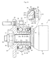
- a driving-wheel bearing device includes the following as main components: a hub wheel 10 and inner race 20 which serve as inner members; double-row rolling elements 30 and 40; an outer race 50 which serves as an outer member; and a constant velocity universal joint 60.
- a hub wheel 10 and inner race 20 which serve as inner members
- double-row rolling elements 30 and 40 which serves as inner members
- an outer race 50 which serves as an outer member
- a constant velocity universal joint 60 an outer side of a vehicle in a state in which the bearing device is assembled to the vehicle.
- the hub wheel 10 has an outboard-side inner raceway surface 12 formed on an outer peripheral surface thereof, and includes a wheel attachment flange 14 for allowing a wheel (not shown) to be attached thereto.
- Hub bolts 16 for fixing a wheel disk are equiangularly embedded in the wheel attachment flange 14.
- the inner race 20 is fitted to a small-diameter step portion 18 formed on the outer peripheral surface of the hub wheel 10, and an inboard-side inner raceway surface 22 is formed on an outer peripheral surface of the inner race 20.
- a female spline 11 for coupling the constant velocity universal joint 60 with the hub wheel 10 so that torque can be transmitted therebetween is formed on an inner peripheral surface of a shaft hole of the hub wheel 10.
- the inner race 20 is press-fitted to the small-diameter step portion 18 of the hub wheel 10 with adequate tightening margin for the purpose of preventing creep.
- the outboard-side inner raceway surface 12 formed on the outer peripheral surface of the hub wheel 10 and the inboard-side inner raceway surface 22 formed on the outer peripheral surface of the inner race 20 constitute double-row inner raceway surfaces.
- the inner race 20 is press-fitted to the small-diameter step portion 18 of the hub wheel 10, and the end portion of the small-diameter step portion 18 of the hub wheel 10 is crimped outward. As a result, the inner race 20 is prevented from slipping off by a crimped portion 13 thus formed, and is integrated with the hub wheel 10, to thereby apply preload to a bearing section 70.
- the outer race 50 has double-row outer raceway surfaces 52 and 54 formed on an inner peripheral surface thereof and opposed to the inner raceway surfaces 12 and 22 of the hub wheel 10 and the inner race 20, and includes a vehicle body attachment flange 56 for being attached to a vehicle body (not shown).
- the vehicle body attachment flange 56 is fixed, with use of an attachment hole 58, by bolts or the like to a knuckle extending from a suspension device (not shown) of a vehicle body.
- the bearing section 70 has a double-row angular ball bearing structure, specifically, has the following structure: the rolling elements 30 and 40 are interposed between the inner raceway surfaces 12 and 22 formed on the outer peripheral surfaces of the hub wheel 10 and inner race 20 and the outer raceway surfaces 52 and 54 formed on the inner peripheral surface of the outer race 50, the rolling elements 30 and 40 in respective rows being rotatably and equiangularly retained by retainers 32 and 42.
- a pair of seals 34 and 44 for sealing annular spaces between the outer race 50 and the hub wheel 10 and between the outer race 50 and the inner race 20 so as to be held in sliding-contact with the outer peripheral surfaces of the hub wheel 10 and inner race 20 are fitted to the inner periphery at both end portions of the outer race 50. Further, the seals 34 and 44 prevent leakage of grease filling the inside and intrusion of water and foreign matters from the outside.
- An outer joint member 62 of the constant velocity universal joint 60 is coupled with the hub wheel 10 described above, and hence a bearing device is constituted.
- the outer joint member 62 of the constant velocity universal joint 60 is provided at one end of an intermediate shaft (not shown) constituting a drive shaft, and is constituted by the following: a cup-shaped mouth section 64 housing inner components (not shown) including an inner joint member, balls, and a cage; and a stem section 66 extending integrally from a proximal portion of the mouth section 64 in an axial direction.
- a male spline 68 for coupling the hub wheel 10 described above with the constant velocity universal joint 60 so that torque can be transmitted therebetween is formed on an outer peripheral surface of the stem section 66.
- the stem section 66 of the outer joint member 62 is press-fitted to the shaft hole of the hub wheel 10, and the male spline 68 formed on the outer peripheral surface of the stem section 66 and the female spline 11 formed on the inner peripheral surface of the shaft hole of the hub wheel 10 are fitted to each other. In this manner, torque can be transmitted.
- an annular plate 80 excellent in sliding properties is interposed between opposite surfaces of a shoulder portion 61 of the outer joint member 62 and the crimped portion 13 of the hub wheel 10, and a nut 72 is tightened to a male-screw portion 65 formed at an end portion of the stem section 66.
- the constant velocity universal joint 60 is fixed to the hub wheel 10.
- the constant velocity universal joint 60 and the hub wheel 10 may be fixed to each other with a bolt other than the nut 72.
- the plate 80 is sandwiched between the opposite surfaces of the shoulder portion 61 of the outer joint member 62 and the crimped portion 13 of the hub wheel 10.
- the plate 80 interposed between the opposite surfaces of the shoulder portion 61 of the outer joint member 62 and the crimped portion 13 of the hub wheel 10 is provided with a molybdenum (MoS 2 ) coating layer or a fluorine-resin coating layer 81 and has a plate thickness ranging from 0.5 mm to 2 mm. Notethat, the thickness of the plate 80 preferably ranges from 0.8 mm to 1 mm.
- the plate 80 endowed with excellent sliding properties due to formation of the molybdenum coating layer or the fluorine-resin coating layer 81 is interposed between the opposite surfaces of the shoulder portion 61 of the outer joint member 62 and the crimped portion 13 of the hub wheel 10.
- frictional resistance is reduced between the bearing section 70 and the outer joint member 62 so that positive sliding is caused.
- abrupt sliding is not caused between the bearing section 70 and the outer joint member 62, and hence generation of stick-slip noise is prevented.
- the thickness of the plate 80 excellent in sliding properties is set to 0.5 mm or more, the strength of the plate 80 is secured. High surface-pressure applied by the axial force to the plate 80 prevents deformation or the like of the plate 80, and hence reduction of the axial force is prevented over a long period of time. Anti stick-slip properties are secured in this manner. Meanwhile, when the thickness of the plate 80 is set to 2 mm or less, compact design can be secured without increase in axial dimension of the bearing device.
- the thickness of the plate 80 is less than 0.5 mm, it is difficult to secure the strength of the plate 80, which may lead to such a risk that the plate 80 is liable to be deformed in a case of being applied with high surface-pressure by the axial force, and that the axial force is reduced, which may cause a breakage of the plate 80. Further, when the thickness of the plate 80 is more than 2 mm, the axial dimension of the bearing device is increased, which leads to difficulty in compactification of the device.
- the film thickness of the molybdenum coating layer or the fluorine-resin coating layer 81 formed on the plate 80 is set within a range from 2 ⁇ m to 30 ⁇ m.
- the film thickness of the molybdenum coating layer or the fluorine-resin coating layer 81 is set to 2 ⁇ m or more, the molybdenum coating layer or the fluorine-resin coating layer 81 is not worn early.
- the film thickness of the molybdenum coating layer or the fluorine-resin coating layer 81 is set to 30 ⁇ m or less, use amount of a coating material is minimized, and hence cost increase is not involved.
- the coating layer 81 itself is not crushed even when high surface-pressure is applied by the axial force to the plate 80, and hence reduction of the axial force is prevented, and hence the nut 72 is prevented from being loosened.
- the film thickness of the coating layer 81 is less than 2 ⁇ m, there is a risk that the coating layer 81 is worn early. Further, when the film thickness of the coating layer 81 is more than 30 ⁇ m, use amount of a coating material is increased, which leads to cost increase. In addition, the coating layer 81 itself is crushed when high surface-pressure is applied by the axial force to the plate 80, which leads to reduction of the axial force and formation of a gap between the opposite surfaces of an inboard-side end portion of the bearing section and the shoulder portion of the outer joint member.
- the wheel bearing device When the wheel bearing device is of a type that the inboard-side end portion of the bearing section is not crimped outward (type that the inner race of the bearing section and the shoulder portion of the constant velocity universal joint are held indirect contact with each other), there occurs a failure of impairing durability of the bearing section.
- the material of the plate 80 is stainless steel.
- the plate 80 is formed of stainless steel as just described above, the plate 80 itself can be caused to yield corrosion-resistance effect. As a result, generation of stain is prevented, and hence use environment can also be coped with in which corrosion-resistance properties such as those of automobiles are required over a long period of time.
- the yield strength of the plate 80 is set to 205 N/mm 2 or more.
- the yield strength of the plate 80 is set to 205 N/mm 2 or more as just described above, deformation of the plate 80 is prevented even when high surface-pressure is applied by the axial force to the plate 80, and hence reduction of the axial force is prevented.
- the present invention is applied to a bearing device of the following type: the small-diameter step portion 18 is formed on the outer peripheral surface of the hub wheel 10, the one-side inner raceway surface 12 being formed on the outer peripheral surface; the inner race 20 provided with the other-side inner raceway surface 22 is press-fitted to the small-diameter step portion 18; and the end portion of the small-diameter step portion 18 of the hub wheel 10 is crimped.
- the present invention is not limited thereto.
- the present invention is applicable to a bearing device of the following type: a pair of inner races 20a and 20b are fitted to the outer peripheral surface of the hub wheel 10; an outboard-side inner raceway surface 22a is formed on an outer peripheral surface of the one-side inner race 20a; and an inboard-side inner raceway surface 22b is formed on an outer peripheral surface of the other-side inner race 20b.
- an inboard-side end portion of the other-side inner race 20b positioned on an inboard side is opposed to the shoulder portion 61 of the outer joint member 62.
- the plate 80 described in the first embodiment is interposed between the inboard-side end portion of the inner race 20b and the shoulder portion 61 of the outer joint member 62.
- the plate 80 is similar to that described above in the first embodiment in constitution, that is, in the following points: the molybdenum coating layer or the fluorine-resin coating layer 81 is formed thereon and the plate 80 has a plate thickness ranging from 0.5 mm to 2 mm; the film thickness of the molybdenum coating layer or the fluorine-resin coating layer 81 is set within a range from 2 ⁇ m to 30 ⁇ m; the material of the plate 80 is stainless steel; and the yield strength of the plate 80 is set to 205 N/mm 2 or more, and in functions and advantages. Therefore, redundant description thereof is omitted.
- the plate 80 also has an advantage of preventing durability of the bearing section 70 from being reduced owing to reduction of the axial force.
- a plate 82 may be used which has an annular portion 82a and a cylindrical portion 82b.
- the present invention is applied to a bearing device of a type that the end portion of the small-diameter step portion 18 of the hub wheel 10 is crimped; in the fourth embodiment illustrated in FIG. 4 , similar to the second embodiment, the present invention is applied to a bearing device of a type that the pair of inner races 20a and 20b are fitted to the outer peripheral surface of the hub wheel 10.
- the plate 82 according to the third embodiment has a structure constituted by the following: the annular portion 82a interposed between the two opposite surfaces of the shoulder portion 61 of the outer joint member 62 and the crimped portion 13 of the hub wheel 10; and the cylindrical portion 82b formed of an outer peripheral edge of the annular portion 82a, the outer peripheral edge being elongated to an axial inboard side and fitted to the shoulder portion 61 of the outer joint member 62.
- the plate 82 according to the fourth embodiment has a structure constituted by the following: the annular portion 82a interposed between the two opposite surfaces of the shoulder portion 61 of the outer joint member 62 and the inboard-side end portion of the inner race 20b; and the cylindrical portion 82b formed of an outer peripheral edge of the annular portion 82a, the outer peripheral edge being elongated to an axial inboard side and fitted to the shoulder portion 61 of the outer joint member 62.
- Each of the plates 82 is provided with a molybdenum coating layer or a fluorine-resin coating layer 83 and has a plate thickness ranging from 0.5 mm to 2 mm. Further, the film thickness of the molybdenum coating layer or the fluorine-resin coating layer 83 formed on each of the plates 82 is set within a range from 2 ⁇ m to 30 ⁇ m. In addition, the material of the plates 82 is stainless steel, and the yield strength thereof is set to 205 N/mm 2 or more. Functions and advantages yielded by the annular portion 82a of each of the plates 82 constituted as described above are similar to those of the annular plates 80 in the first embodiment illustrated in FIG. 1 and the second embodiment illustrated in FIG. 2 , and hence redundant description thereof is omitted.
- each of the plate 82 can be assembled to the outer joint member 62 by fitting of the cylindrical portion 82b of each of the plates 82 to the shoulder portion 61 of the outer joint member 62.
- the plates 82 can be handled more easily.
- the annular portion 82a of the plate 82 can be easily positioned between the opposite surfaces of the crimped portion 13 of the hub wheel 10 and the shoulder portion 61 of the outer joint member 62; in the case of the fourth embodiment, the annular portion 82a of the plate 82 can be easily positioned between the opposite surfaces of the inboard-side end portion of the inner race 20b and the shoulder portion 61 of the outer joint member 62.
- each of the plates 82 has a structure in which an outer peripheral edge of the annular portion 82a is elongated to the axial inboard side and the cylindrical portion 82b is fitted to the shoulder portion 61 of the outer joint member 62, and hence each of the plates 82 can be assembled to the outer joint member 62.
- the present invention is not limited thereto, and it is also possible to use plates 84 and 86 which respectively have structures in a fifth embodiment of the present invention illustrated in FIG. 5 and a sixth embodiment of the present invention illustrated in FIG. 6 .
- the present invention is applied to a bearing device of a type that the end portion of the small-diameter step portion 18 of the hub wheel 10 is crimped; in the sixth embodiment illustrated in FIG. 6 , similar to the fourth embodiment, the present invention is applied to a bearing device of a type that the pair of inner races 20a and 20b are fitted to the outer peripheral surface of the hub wheel 10.
- the plate 84 according to the fifth embodiment has a structure constituted by the following: an annular portion 84a interposed between the two opposite surfaces of the shoulder portion 61 of the outer joint member 62 and the crimped portion 13 of the hub wheel 10; and a cylindrical portion 84b formed of an outer peripheral edge of the annular portion 84a, the outer peripheral edge being elongated to an axial outboard side and fitted to the inboard-side end portion of the inner race 20.
- the plate 86 according to the sixth embodiment has a structure constituted by the following: the annular portion 84a interposed between the two opposite surfaces of the shoulder portion 61 of the outer joint member 62 and the inboard-side end portion of the inner race 20b; and a cylindrical portion 86b formed of an inner peripheral edge of the annular portion 84a, the outer peripheral edge being elongated to the axial outboard side and fitted to the inboard-side end portion of the inner race 20b.
- the plates 84 and 86 are provided with molybdenum coating layers or fluorine-resin coating layers 85 and 87, respectively, and each has a plate thickness ranging from 0.5 mm to 2 mm. Further, the film thickness of the molybdenum coating layer or the respective fluorine-resin coating layers 85 and 87 formed on the plates 84 and 86 is set within a range from 2 ⁇ m to 30 ⁇ m. In addition, the material of the plates 84 and 86 is stainless steel, and the yield strength thereof is set to 205 N/mm 2 or more.
- the plates 84 and 86 can be assembled to the bearing section 70 by fitting of the cylindrical portion 84b of the plate 84 to the crimped portion 13 of the hub wheel 10 in the case of the fifth embodiment, and by fitting of the cylindrical portion 86b of the plate 86 to the inboard-side end portion of the inner race 20b in the case of the sixth embodiment.
- the plates 84 and 86 can be handled more easily.
- the annular portion 84a of the plate 84 can be easily positioned between the opposite surfaces of the crimped portion 13 of the hub wheel 10 and the shoulder portion 61 of the outer joint member 62; in the case of the sixth embodiment, the annular portion 86b of the plate 86 can be easily positioned between the opposite surfaces of the inboard-side end portion of the inner race 20b and the shoulder portion 61 of the outer joint member 62.
- a plate 180 is sandwiched by a predetermined tightening force (axial force) of the nut 72 between the opposite surfaces of the shoulder portion 61 of the outer joint member 62 and the crimped portion 13 of the hub wheel 10.
- the plate 180 interposed between the opposite surfaces of the shoulder portion 61 of the outer joint member 62 and the crimped portion 13 of the hub wheel 10 is endowed with predetermined sliding properties by coating of surfaces of a substrate 181 thereof with a film 182 containing a fluorine resin or molybdenum disulfide.
- the plate 180 is subjected to coating with the film 182 containing a fluorine resin or molybdenum disulfide. Any of the following cases may be applied: a case of effecting coating with the film 182 containing only a fluorine resin; a case of effecting coating with the film 182 containing only molybdenum disulfide; and a case of effecting coating with a film 182 containing both a fluorine resin and molybdenum disulfide.
- the plate 180 endowed with excellent sliding properties due to coating of the surfaces of the substrate 181 is interposed between the opposite surfaces of the shoulder portion 61 of the outer joint member 62 and the crimped portion 13 of the hub wheel 10.
- frictional resistance is reduced between the bearing section 70 and the outer joint member 62 so that positive sliding is caused.
- abrupt sliding is not caused between the bearing section 70 and the outer joint member 62, and hence generation of stick-slip noise is prevented.
- both the outer-joint-member-side surface and hub-wheel-side surface of the substrate 181 are subjectedtocoating.
- only the outer-joint-member-side surface of the substrate 181 may be subjected to coating.
- a recess groove 90 into which an inner periphery of the plate 180 is fitted is formed on the shoulder portion 61 of the outer joint member 62 with which the plate 180 illustrated in FIGS. 8A and 9 comes into contact, and an escape portion 91 is provided at an innermost part of the recess groove 90 into which the plate 180 is fitted.
- the recess groove 90 has a large-diameter inlet portion 90a through which the plate 180 is inserted and a small-diameter groove-bottom portion 90b into which the plate 180 is fitted.
- the recess groove 90 into which the inner periphery of the plate 180 is fitted is provided to the shoulder portion 61 of the outer joint member 62.
- the plate 180 can be easily assembled to the shoulder portion 61 of the outer joint member 62, and easily positioned and interposed between the crimped portion 13 of the hub wheel 10 and the shoulder portion 61 of the outer joint member 62 in a state in which the plate 180 is assembled to the outer joint member 62.
- the escape portion 91 is provided at the innermost part of the recess groove 90. With this configuration, fitting work is facilitated when the plate 180 is fitted into the recess groove 90 of the shoulder portion 61 of the outer joint member 62.
- the inner diameter of the plate 180 is defined as d 1 , the thickness thereof as t, the diameter of the inlet portion 90a of the recess groove 90 of the outer joint member 62 as D 1 , the diameter of the groove-bottom portion 90b as D 2 , and an axial length as L, the following relations are established: D 2 ⁇ d 1 ⁇ D 1 and t ⁇ L.
- the plate 180 can be easily assembled to the extent of being attachable by hand.
- the present invention is applied to a bearing device of the following type: the small-diameter step portion 18 is formed on the outer peripheral surface of the hub wheel 10, the one-side inner raceway surface 12 being formed on the outer peripheral surface; the inner race 20 provided with the other-side inner raceway surface 22 is press-fitted to the small-diameter step portion 18; and the end portion of the small-diameter step portion 18 of the hub wheel 10 is crimped.
- the present invention is not limited thereto.
- the present invention is applicable to a bearing device of the following type: the pair of inner races 20a and 20b are fitted to the outer peripheral surface of the hub wheel 10; the outboard-side inner raceway surface 22a is formed on the outer peripheral surface of the one-side inner race 20a; and the inboard-side inner raceway surface 22b is formed the outer peripheral surface of the other-side inner race 20b.
- the inboard-sideendportionof the other-side inner race 20b positioned on the inboard side is opposed to the shoulder portion 61 of the outer joint member 62.
- the plate 180 described in the seventh embodiment is interposed between the inboard-side end portion of the inner race 20b and the shoulder portion 61 of the outer joint member 62.
- the present invention is not limited thereto, and it is also possible to use a plate 184 as in a ninth embodiment of the present invention illustrated in FIG. 12 and a tenth embodiment of the present invention illustrated in FIG. 13 .
- the present invention is applied to a bearing device of a type that the inner race 20 is press-fitted to the small-diameter step portion 18 of the hub wheel 10 and then the end portion of the small-diameter step portion 18 of the hub wheel 10 is crimped.
- the plate 184 is interposed between the crimped portion 13 of the hub wheel 10 and the shoulder portion 61 of the outer joint member 62.
- the present invention is applied to a bearing device of a type that the pair of inner races 20a and 20b are fitted to the outer peripheral surface of the hub wheel 10.
- the plate 184 is interposed between the inboard-side end portion of the inner race 20b and the shoulder portion 61 of the outer joint member 62.
- claw-like protrusions 187 are provided on an inner periphery of the plate 184.
- three protrusions 187 are equiangularly formed on the inner periphery of the plate 184.
- the inner diameter d 1 of the plate 184 is defined as an inner diameter measured from each of the portions corresponding to the protrusions 187 provided on the inner periphery thereof.
- the claw-like protrusions 187 on the inner periphery of the plate 184 as in those ninth and tenth embodiments, mountability of the plate 184 is enhanced.
- the claw-like protrusions 187 for example, at three points along the circumferential direction of the inner periphery of the plate 184, only the parts corresponding to the protrusions 187 come into contact with the shoulder portion 61 of the outer joint member 62 in the circumferential direction of the inner periphery of the plate 184, and hence the plate 184 is more easily mounted to the outer joint member 62.
- an inner end portion of each of the protrusions 187 is formed in a shape of being bent to the crimped portion 13 of the hub wheel 10, and hence the plate 184 can be more easily fitted and less liable to be disengaged.
- lubricant may be interposed in any one of a gap between each of the plate 180 and 184 and the shoulder portion 61 of the outer joint member 62 and a gap between each of the plate 180 and 184 and the crimped portion 13 of the hub wheel 10.
- lubricant may be interposed in both the gap between each of the plate 180 and 184 and the shoulder portion 61 of the outer joint member 62 and the gap between each of the plate 180 and 184 and the crimped portion 13 of the hub wheel 10.
Landscapes
- Engineering & Computer Science (AREA)
- Mechanical Engineering (AREA)
- General Engineering & Computer Science (AREA)
- Rolling Contact Bearings (AREA)
Abstract
Description
- The present invention relates to a driving-wheel bearing device which rotatably supports a driving wheel (front wheel of a front-engine front-drive (FF) vehicle, rear wheel of a front-engine rear-drive (FR) vehicle, and all wheels of a four-wheel drive (4WD) vehicle) with respect to a suspension device for, for example, an automobile.
- Bearing devices for automobiles include ones for driving wheels and ones for driven wheels, and there have been proposed ones of various types in accordance with respective applications. For example,
FIG. 16 illustrates a driving-wheel bearing device. The bearing device includes the following as main components: ahub wheel 210 and aninner race 220, double-row rolling elements outer race 250, and a constant velocityuniversal joint 260. - The
hub wheel 210 has an outboard-sideinner raceway surface 212 formed on an outer peripheral surface thereof, and includes awheel attachment flange 214 for allowing a wheel (not shown) to be attached thereto.Hub bolts 216 for fixing a wheel disk are equiangularly embedded in thewheel attachment flange 214. Theinner race 220 is fitted to a small-diameter step portion 218 formed on the outer peripheral surface of thehub wheel 210, and an inboard-sideinner raceway surface 222 is formed on an outer peripheral surface of theinner race 220. Afemale spline 211 for coupling the constant velocityuniversal joint 260 with thehub wheel 210 so that torque can be transmitted therebetween is formed on an inner peripheral surface of a shaft hole of thehub wheel 210. - The
inner race 220 is press-fitted to the small-diameter step portion 218 of thehub wheel 210 with adequate tightening margin for the purpose of preventing creep. The outboard-sideinner raceway surface 212 formed on the outer peripheral surface of thehub wheel 210 and the inboard-sideinner raceway surface 222 formed on the outer peripheral surface of theinner race 220 constitute double-row inner raceway surfaces. Theinner race 220 is press-fitted to the small-diameter step portion 218 of thehub wheel 210, and the end portion of the small-diameter step portion 218 of thehub wheel 210 is crimped outward. As a result, theinner race 220 is prevented from slipping off by a crimpedportion 213 thus formed, and is integrated with thehub wheel 210, to thereby apply preload to abearing section 270. - The
outer race 250 has double-rowouter raceway surfaces inner raceway surfaces hub wheel 210 and theinner race 220, and includes a vehiclebody attachment flange 256 for being attached to a vehicle body (not shown). The vehiclebody attachment flange 256 is fixed, with use of anattachment hole 258, by bolts or the like to a knuckle extending from a suspension device (not shown) of a vehicle body. - The
bearing section 270 has a double-row angular ball bearing structure, specifically, has the following structure: therolling elements inner raceway surfaces hub wheel 210 andinner race 220 and theouter raceway surfaces outer race 250; therolling elements retainers - At the openings on both ends of the
bearing section 270, a pair ofseals outer race 250 and thehub wheel 210 and between theouter race 250 and theinner race 220 so as to be held in sliding-contact with the outer peripheral surfaces of thehub wheel 210 andinner race 220 are fitted to the inner periphery at both end portions of theouter race 250. Further, theseals - An
outer joint member 262 of the constant velocityuniversal joint 260 is coupled with thehub wheel 210, and hence a bearing device is constituted. The outerjoint member 262 of the constant velocityuniversal joint 260 is provided at one end of an intermediate shaft (not shown) constituting a drive shaft, and is constituted by the following: a cup-shaped mouth section 264 housing inner components (not shown) including an inner joint member, balls, and a cage; and astem section 266 extending integrally from a proximal portion of themouth section 264 in an axial direction. Amale spline 268 for coupling thehub wheel 210 with the constant velocityuniversal joint 260 so that torque can be transmitted therebetween is formed on an outer peripheral surface of thestem section 266. - The
stem section 266 of theouter joint member 262 is press-fitted to the shaft hole of thehub wheel 210, and themale spline 268 formed on the outer peripheral surface of thestem section 266 and thefemale spline 211 formed on the inner peripheral surface of the shaft hole of thehub wheel 210 are fitted to each other. In this manner, torque can be transmitted. Further, in a state in which opposite surfaces of the crimpedportion 213 of thehub wheel 210 and ashoulder portion 261 of theouter joint member 262 are hit against each other, anut 272 is tightened to a male-screw portion 265 formed at an end portion of thestem section 266. In this manner, the constant velocityuniversal joint 260 is fixed to thehub wheel 210. - Incidentally, in the driving-wheel bearing device, the crimped
portion 213 of thehub wheel 210 of thebearing section 270 and theshoulder portion 261 of theouter joint member 262 are in a contact state of being hit against each other. Thus, upon starting of a vehicle, there is a risk that stick-slip noise commonly known as squeaking noise is generated between the crimpedportion 213 of thehub wheel 210 of thebearing section 270 and theshoulder portion 261 of theouter joint member 262. - The stick-slip noise means noise generated by abrupt sliding caused as follows: upon starting of a vehicle, although rotational torque is applied from the
outer joint member 262 of the constant velocityuniversal joint 260 with respect to thehub wheel 210 of thebearing section 270 in a static state so as to be transmitted from theouter joint member 262 to thehub wheel 210 through intermediation of thefemale spline 211 and themale spline 268, the transmitted torque between thebearing section 270 and theouter joint member 262 varies and theouter joint member 262 twists, with the result that abrupt sliding occurs between the crimpedportion 213 of thehub wheel 210 and theshoulder portion 261 of theouter joint member 262. - As means for preventing the stick-slip noise, there has been provided means for sandwiching a plate excellent in sliding properties between the opposite surfaces of an inboard-side end portion of the
bearing section 270 and theshoulder portion 261 of the outer joint member 262 (refer toPatent Literatures 1 and 2, for example). - In
Patent Literatures 1 and 2 mentioned above, the plate is interposed between the opposite surfaces of the inboard-side end portion of thebearing section 270 and theshoulder portion 261 of theouter joint member 262. As a result, frictional resistance is reduced between the opposite surfaces of the inboard-side end portion of thebearing section 270 and theshoulder portion 261 of theouter joint member 262 so that positive sliding is caused. Thus, abrupt sliding is not caused, and hence generation of stick-slip noise is prevented. -
- Patent Literature 1:
JP 2003-97588 A - Patent Literature 2:
JP 2007-508986 A - Incidentally, the bearing devices disclosed in
Patent Literatures 1 and 2, as described above, an annular plate excellent in sliding properties is interposed between the opposite surfaces of the inboard-side end portion of thebearing section 270 and theshoulder portion 261 of theouter joint member 262. In this manner, generation of stick-slip noise is prevented. - However, in those bearing devices, the constant velocity
universal joint 260 is fixed to thehub wheel 210 by an axial force exerted by tightening of thenut 272 to the male-screw portion 265 formed at the end portion of thestem section 266. Thus, owing to deformation and the like of the plate with high surface pressure applied to the plate by the axial force, there is a risk that the axial force is reduced. When the axial force is reduced in this way, a gap is formed between the opposite surfaces of the inboard-side end portion of thebearing section 270 and theshoulder portion 261 of theouter joint member 262. In this context, when corrosion-resistance properties of the plate itself are low, anti stick-slip properties of the plate is impaired owing to corrosion. As a result, the thickness of the plate is reduced owing to the corrosion, which may lead to a risk of further reduction of the axial force. In particular, in a case of a type that the inboard-side end portion of the bearing section is not crimped outward (type that the inner race of the bearing section and the shoulder portion of the constant velocity universal joint are held in direct contact with each other), there occurs a failure of impairing durability of the bearing section. - Further, the surface roughness of the plate prior to coating is not disclosed at all in any of
Patent Literatures 1 and 2 described above. Thus, the applicants of the present invention have focused attention on the surface roughness of the plate prior to coating. - In other words, when the surface roughness of the plate prior to coating is excessively small, adhesion properties between the surface of the plate and a coating material are reduced. Thus, when rotational torque is input in a state in which the plate is interposed between the
bearing section 270 and theshoulder portion 261 of theouter joint member 262, the coating material is caused to be peeled off early, and hence it has been difficult to sufficiently yield the functions of the coating material. In contrast, when the surface roughness prior to coating is excessively large, surface pressure of protruding portions becomes higher with the surface roughness, and hence problems such as early wearing of the coating material occur on that portions. Also in this case, it has been difficult to sufficiently yield the functions of the coating material. - It is therefore an object of the present invention to provide a driving-wheel bearing device preventing reduction of the axial force over a long period of time and being capable of securing anti stick-slip properties.
- In order to achieve the above-mentioned object, according to the present invention, there is provided a driving-wheel bearing device including: an outer member having double-row outer raceway surfaces formed on an inner periphery thereof; an inner member constituted by a hub wheel and an inner race, the inner member having a wheel attachment flange at one end thereof and double-row inner raceway surfaces on an outer periphery thereof; and double-row rolling elements interposed between the double-row outer raceway surfaces of the outer member and the double-row inner raceway surfaces of the inner member, the hub wheel having a shaft hole into which a stem section extending from an outer joint member of a constant velocity universal joint is spline-fitted by being press-fitted, in which a plate having a molybdenum coating layer or a fluorine-resin coating layer formed thereon and having a plate thickness ranging from 0.5 mm to 2 mm is interposed between opposite surfaces of a shoulder portion of the outer joint member and an end portion of the inner member.
- In the present invention, the plate endowed with excellent sliding properties due to formation of the molybdenum coating layer or the fluorine-resin coating layer is interposed between the opposite surfaces of the shoulder portion of the outer joint member and the end portion of the inner member. As a result, even when transmitted torque between the bearing section having the inner member and the outer joint member varies and the outer joint member twists, frictional resistance is reduced between the bearing section and the outer joint member so that positive sliding is caused. Thus, abrupt sliding is not caused between the bearing section and the outer joint member, and hence generation of stick-slip noise is prevented.
- Further, when the thickness of the plate excellent in sliding properties is set to 0.5 mm or more, the strength of the plate is secured. High surface-pressure applied by the axial force to the plate prevents deformation or the like of the plate, and hence reduction of the axial force is prevented. Meanwhile, when the thickness of the plate is set to 2 mm or less, compact design can be secured without increase in axial dimension of the bearing device.
- It is desirable that a film thickness of the molybdenum coating layer or the fluorine-resin coating layer of the present invention be set within a range from 2 µm to 30 µm. When the film thickness of the molybdenum coating layer or the fluorine-resin coating layer is set to 2 µm or more, the molybdenum coating layer or the fluorine-resin coating layer is not worn early. Further, when the film thickness of the molybdenum coating layer or the fluorine-resin coating layer is set to 30 µm or less, use amount of a coating material is minimized, and hence cost increase is not involved. In addition, crush of the coating layer is suppressed even when high surface-pressure is applied by the axial force to the plate, and hence reduction of the axial force is prevented, and hence durability of the bearing section can be secured.
- It is desirable that the material of the plate of the present invention be stainless steel. With this configuration, the plate itself can be caused to yield corrosion-resistance effect, and hence generation of stain is prevented. As a result, it is capable of coping with use environment in which corrosion-resistance properties such as those of automobiles are required over a long period of time.
- It is desirable that a yield strength of the plate of the present invention be set to 205 N/mm2 or more. With this setting, deformation of the plate is prevented even when high surface-pressure is applied by the axial force to the plate, and hence reduction of the axial force is prevented.
- It is desirable that the plate of the present invention be constituted by an annular portion interposed between the two opposite surfaces of the shoulder portion of the outer joint member and the end portion of the inner member and by a cylindrical portion formed of a peripheral edge of the annular portion, the peripheral edge being elongated in an axial direction and fitted to the shoulder portion of the outer joint member. With this structure, when the cylindrical portion of the plate is fitted to the shoulder portion of the outer joint member, the plate can be interposed in a state in which the annular portion is easily positioned between the two opposite surfaces of the end portion of the inner member and the shoulder portion of the outer joint member in a state in which the plate is assembled to the outer joint member.
- Further, it is desirable that the plate of the present invention be constituted by an annular portion interposed between the two opposite surfaces of the shoulder portion of the outer joint member and the end portion of the inner member and by a cylindrical portion formed of a peripheral edge of the annular portion, the peripheral edge being elongated in the axial direction and fitted to the end portion of the inner member. With this structure, when the cylindrical portion of the plate is fitted to the end portion of the inner member, the plate can be interposed in a state in which the annular portion is easily positioned between the two opposite surfaces of the end portion of the inner member and the shoulder portion of the outer joint member in a state in which the plate is assembled to the inner member.
- Further, a driving-wheel bearing device according to the present invention includes: an outer member having double-row outer raceway surfaces formed on an inner periphery thereof; an inner member constituted by a hub wheel and an inner race, the inner member having a wheel attachment flange at one end thereof and double-row inner raceway surfaces on an outer periphery thereof; and double-row rolling elements interposed between the double-row outer raceway surfaces of the outer member and the double-row inner raceway surfaces of the inner member, the hub wheel having a shaft hole into which a stem section extending from an outer joint member of a constant velocity universal joint is spline-fitted by being press-fitted, in which: a plate endowed with predetermined sliding properties by coating of at least one surface of a substrate is interposed between opposite surfaces of a shoulder portion of the outer joint member and an end portion of the inner member; and a surface roughness of the coating-object substrate is set to be Rz=0.2∼15.0. Note that, Rz means one of surface parameters defined in JIS, specifically, ten-point average roughness.
- In this context, the description "at least one surface of a substrate" encompasses the following cases: coating only the substrate surface opposite to the shoulder portion of the outer joint member; coating only the substrate surface opposite to the end portion of the inner member; and coating both the substrate surfaces.
- In the present invention, the plate endowed with predetermined sliding properties due to coating of the surface of the substrate is interposed between the opposite surfaces of the shoulder portion of the outer joint member and the end portion of the inner member. As a result, even when transmitted torque between the bearing section having the inner member and the outer joint member varies and the outer joint member twists, frictional resistance is reduced between the bearing section and the outer j ointmember so that positive sliding is caused. Thus, abrupt sliding is not caused between the bearing section and the outer joint member, and hence generation of stick-slip noise is prevented.
- By setting of the surface roughness of the coating-object substrate of the plate to be Rz=0.2∼15.0, a coating material is more easily applied onto the surfaces of the substrate, and hence adhesion properties are enhanced. As a result, even when rotational torque is input, problems such as early peeling-off and early wearing of the coating material are prevented, and hence functions of the coating material is sufficiently yielded more easily.
- In the present invention, it is desirable that a recess groove into which an inner periphery of the plate is fitted be formed on the shoulder portion of the outer joint member. When the recess groove into which the inner periphery of the plate is fitted is provided to the shoulder portion of the outer joint member, the plate can be easily assembled to the shoulder portion of the outer joint member, and easily positioned and interposed between the end portion of the inner wheel and the shoulder portion of the outer joint member in a state in which the plate is assembled to the outer joint member.
- It should be noted that it is desirable that an escape portion be provided at an innermost part of the recess groove into which the plate is fitted. When the escape portion is provided as just described above, the fitting work is facilitated when the plate is fitted into the recess groove of the shoulder portion of the outer joint member.
- In the present invention, it is desirable that claw-like protrusions be provided on the inner periphery of the plate. With this structure, mountability of the plate is enhanced. In other words, with provision of the claw-like protrusions, for example, at a plurality of points along the circumferential direction of the inner periphery of the plate, only the parts corresponding to the protrusions come into contact with the shoulder portion of the outer joint member in the circumferential direction of the inner periphery of the plate, and hence the plate is more easily mounted to the outer joint member.
- It is desirable that the plate of the present invention be endowed with the predetermined sliding properties by being subjected to coating with a film containing at least one of a fluorine resin and molybdenum disulfide. In order to easily secure the predetermined sliding properties of the plate, it is only necessary that the plate be subjected to coating with the film containing at least one of a fluorine resin and molybdenum disulfide.
- In this context, the description "the film containing at least one of a fluorine resin andmolybdenumdisulfide" encompasses the following cases: coating only with the film containing a fluorine resin; coating only with the film containing molybdenum disulfide; and coating with the film containing both a fluorine resin and molybdenum disulfide.
- In the present invention, it is desirable that lubricant be interposed in at least one of a gap between the plate and the shoulder portion of the outer joint member and a gap between the plate and the end portion of the inner member. With this structure, the frictional resistance is further reduced between the bearing section and the outer joint member so that positive sliding easily occurs, with the result that generation of stick-slip noise is more reliably prevented.
- In this context, the description "at least one of a gap between the plate and the shoulder portion of the outer joint member and a gap between the plate and the end portion of the inner member" encompasses the following cases: interposing lubricant only in the gap between the plate and the shoulder portion of the outer joint member; interposing lubricant only in the gap between the plate and the end portion of the inner member; and interposing lubricant in both the gaps.
- Note that, the bearing device is applicable to a bearing device of the following type: the small-diameter step portion is formed on the outer peripheral surface of the hub wheel, the one-side inner raceway surface being formed on the outer peripheral surface; the inner race provided with the other-side inner raceway surface is press-fitted to the small-diameter step portion; and the end portion of the small-diameter step portion of the hub wheel is crimped. In this case, the crimped portion of the hub wheel is opposed to the shoulder portion of the outer joint member.
- Further, other than the bearing device of the type described above, the bearing device is also applicable to a bearing device of the following type: the pair of inner races are fitted to the outer peripheral surface of the hub wheel; the outboard-side inner raceway surface is formed on the outer peripheral surface of the one-side inner race; and the inboard-side inner raceway surface is formed on the outer peripheral surface of the other-side inner race. In this case, an end portion of the other-side inner race positioned on the inboard-side is opposed to the shoulder portion of the outer joint member.
- According to the present invention, upon starting of a vehicle, in a case where rotational torque is applied from the outer joint member of the constant velocity universal joint with respect to the hub wheel of the bearing section in a static state, even when the transmitted torque between the bearing section having the inner member and the outer joint member varies and the outer joint member twists, frictional resistance is reduced between the bearing section and the outer joint member so that positive sliding is caused. Thus, abrupt sliding is not caused between the bearing section and the outer joint member. As a result, generation of stick-slip noise is prevented, and hence it is possible to enhance quietness and to eliminate unpleasant feeling of drivers.
- Further, when the thickness of the plate excellent in sliding properties is set to 0.5 mm to 2 mm, the following advantages can be obtained: the strength of the plate is secured; high surface-pressure applied by the axial force to the plate prevents deformation or the like of the plate, and hence reduction of the axial force is prevented over a long period of time; and anti stick-slip properties are secured. As a result, it is possible to provide a compact driving-wheel bearing device.
- In addition, by setting of the surface roughness of the coating-object substrate to be Rz=0.2∼15.0, a coating material is more easily applied onto the surfaces of the substrate, and hence adhesion properties are enhanced. As a result, even when rotational torque is input, problems such as early peeling-off and early wearing of the coating material are prevented, and hence functions of the coating materialissufficiently yielded moreeasily. Consequently, it is possible to provide a driving-wheel bearing device endowed with anti stick-slip properties secured over a long period of time.
-
- [
FIG. 1 ] A vertical sectional view illustrating an application example of a first embodiment of the present invention, in which a plate is interposed between a crimped portion of a hub wheel and a shoulder portion of an outer joint member. - [
FIG. 2 ] A vertical sectional view illustrating an application example of a second embodiment of the present invention, in which the plate is interposed between an inboard-side end portion of an inner race and the shoulder portion of the outer joint member. - [
FIG. 3 ] A vertical sectional view illustrating an application example of a third embodiment of the present invention, in which a plate assembled to the outer joint member is interposed between the crimped portion of the hub wheel and the shoulder portion of the outer joint member. - [
FIG. 4 ] A vertical sectional view illustrating an application example of a fourth embodiment of the present invention, in which the plate assembled to the outer joint member is interposed between the inboard-side end portion of the inner race and the shoulder portion of the outer joint member. - [
FIG. 5 ] A vertical sectional view illustrating an application example of a fifth embodiment of the present invention, in which a plate assembled to a bearing section is interposed between the crimped portion of the hub wheel and the shoulder portion of the outer joint member. - [
FIG. 6 ] A vertical sectional view illustrating an application example of a sixth embodiment of the present invention, in which a plate assembled to the bearing section is interposed between the inboard-side end portion of the inner race and the shoulder portion of the outer joint member. - [
FIG. 7 ] A vertical sectional view illustrating an application example of a seventh embodiment of the present invention, in which a plate is interposed between the crimped portion of the hub wheel and the shoulder portion of the outer joint member. - [
FIG. 8A ] A partially enlarged sectional view of the plate ofFIG. 7 . - [
FIG. 8B ] A partially enlarged front view of the shoulder portion of the outer joint member ofFIG. 7 . - [
FIG. 9 ] A side view of the plate having a radially-inner circular shape. - [
FIG. 10 ] A partially enlarged view of a state in which the plate ofFIG. 9 is assembled to the shoulder portion of the outer joint member. - [
FIG. 11 ] A vertical sectional view illustrating an application example of an eighth embodiment of the present invention, in which the plate is interposed between the inboard-side end portion of the inner race and the shoulder portion of the outer joint member. - [
FIG. 12 ] A vertical sectional view illustrating an application example of a ninth embodiment of the present invention, in which a plate is interposed between the crimped portion of the hub wheel and the shoulder portion of the outer joint member. - [
FIG. 13 ] A vertical sectional view illustrating an application example of a tenth embodiment of the present invention, in which the plate is interposed between the inboard-side end portion of the inner race and the shoulder portion of the outer joint member. - [
FIG. 14 ] A side view of the plate having protrusions provided on an inner periphery thereof. - [
FIG. 15 ] A partially enlarged view of a state in which the plate ofFIG. 14 is assembled to the shoulder portion of the outer joint member. - [
FIG. 16 ] A vertical sectional view illustrating a conventional example of a driving-wheel bearing device. - In the following, embodiments of a driving-wheel bearing device according to the present invention are described in detail. A driving-wheel bearing device according to a first embodiment illustrated in
FIG. 1 includes the following as main components: ahub wheel 10 andinner race 20 which serve as inner members; double-row rolling elements outer race 50 which serves as an outer member; and a constant velocityuniversal joint 60. Note that, in the following description, an outer side of a vehicle in a state in which the bearing device is assembled to the vehicle is referred to as an outboard side (left side in the figures), and a middle side of the vehicle is referred to as an inboard side (right side in the figures). - The
hub wheel 10 has an outboard-sideinner raceway surface 12 formed on an outer peripheral surface thereof, and includes awheel attachment flange 14 for allowing a wheel (not shown) to be attached thereto.Hub bolts 16 for fixing a wheel disk are equiangularly embedded in thewheel attachment flange 14. Theinner race 20 is fitted to a small-diameter step portion 18 formed on the outer peripheral surface of thehub wheel 10, and an inboard-sideinner raceway surface 22 is formed on an outer peripheral surface of theinner race 20. Afemale spline 11 for coupling the constant velocity universal joint 60 with thehub wheel 10 so that torque can be transmitted therebetween is formed on an inner peripheral surface of a shaft hole of thehub wheel 10. - The
inner race 20 is press-fitted to the small-diameter step portion 18 of thehub wheel 10 with adequate tightening margin for the purpose of preventing creep. The outboard-sideinner raceway surface 12 formed on the outer peripheral surface of thehub wheel 10 and the inboard-sideinner raceway surface 22 formed on the outer peripheral surface of theinner race 20 constitute double-row inner raceway surfaces. Theinner race 20 is press-fitted to the small-diameter step portion 18 of thehub wheel 10, and the end portion of the small-diameter step portion 18 of thehub wheel 10 is crimped outward. As a result, theinner race 20 is prevented from slipping off by a crimpedportion 13 thus formed, and is integrated with thehub wheel 10, to thereby apply preload to abearing section 70. - The
outer race 50 has double-row outer raceway surfaces 52 and 54 formed on an inner peripheral surface thereof and opposed to the inner raceway surfaces 12 and 22 of thehub wheel 10 and theinner race 20, and includes a vehiclebody attachment flange 56 for being attached to a vehicle body (not shown). The vehiclebody attachment flange 56 is fixed, with use of anattachment hole 58, by bolts or the like to a knuckle extending from a suspension device (not shown) of a vehicle body. - The bearing
section 70 has a double-row angular ball bearing structure, specifically, has the following structure: the rollingelements hub wheel 10 andinner race 20 and the outer raceway surfaces 52 and 54 formed on the inner peripheral surface of theouter race 50, the rollingelements retainers - At the openings on both ends of the
bearing section 70, a pair ofseals outer race 50 and thehub wheel 10 and between theouter race 50 and theinner race 20 so as to be held in sliding-contact with the outer peripheral surfaces of thehub wheel 10 andinner race 20 are fitted to the inner periphery at both end portions of theouter race 50. Further, theseals - An outer
joint member 62 of the constant velocityuniversal joint 60 is coupled with thehub wheel 10 described above, and hence a bearing device is constituted. The outerjoint member 62 of the constant velocityuniversal joint 60 is provided at one end of an intermediate shaft (not shown) constituting a drive shaft, and is constituted by the following: a cup-shapedmouth section 64 housing inner components (not shown) including an inner joint member, balls, and a cage; and astem section 66 extending integrally from a proximal portion of themouth section 64 in an axial direction. Amale spline 68 for coupling thehub wheel 10 described above with the constant velocity universal joint 60 so that torque can be transmitted therebetween is formed on an outer peripheral surface of thestem section 66. - The
stem section 66 of the outerjoint member 62 is press-fitted to the shaft hole of thehub wheel 10, and themale spline 68 formed on the outer peripheral surface of thestem section 66 and thefemale spline 11 formed on the inner peripheral surface of the shaft hole of thehub wheel 10 are fitted to each other. In this manner, torque can be transmitted. In the bearing device according to this embodiment, anannular plate 80 excellent in sliding properties is interposed between opposite surfaces of ashoulder portion 61 of the outerjoint member 62 and the crimpedportion 13 of thehub wheel 10, and anut 72 is tightened to a male-screw portion 65 formed at an end portion of thestem section 66. In this manner, the constant velocityuniversal joint 60 is fixed to thehub wheel 10. Note that, the constant velocityuniversal joint 60 and thehub wheel 10 may be fixed to each other with a bolt other than thenut 72. - By a predetermined tightening force (axial force) of the
nut 72, theplate 80 is sandwiched between the opposite surfaces of theshoulder portion 61 of the outerjoint member 62 and the crimpedportion 13 of thehub wheel 10. Theplate 80 interposed between the opposite surfaces of theshoulder portion 61 of the outerjoint member 62 and the crimpedportion 13 of thehub wheel 10 is provided with a molybdenum (MoS2) coating layer or a fluorine-resin coating layer 81 and has a plate thickness ranging from 0.5 mm to 2 mm. Notethat, the thickness of theplate 80 preferably ranges from 0.8 mm to 1 mm. - As described above, the
plate 80 endowed with excellent sliding properties due to formation of the molybdenum coating layer or the fluorine-resin coating layer 81 is interposed between the opposite surfaces of theshoulder portion 61 of the outerjoint member 62 and the crimpedportion 13 of thehub wheel 10. As a result, even when transmitted torque between the bearingsection 70 and the outerjoint member 62 varies and the outerjoint member 62 twists, frictional resistance is reduced between the bearingsection 70 and the outerjoint member 62 so that positive sliding is caused. Thus, abrupt sliding is not caused between the bearingsection 70 and the outerjoint member 62, and hence generation of stick-slip noise is prevented. - Further, when the thickness of the
plate 80 excellent in sliding properties is set to 0.5 mm or more, the strength of theplate 80 is secured. High surface-pressure applied by the axial force to theplate 80 prevents deformation or the like of theplate 80, and hence reduction of the axial force is prevented over a long period of time. Anti stick-slip properties are secured in this manner. Meanwhile, when the thickness of theplate 80 is set to 2 mm or less, compact design can be secured without increase in axial dimension of the bearing device. - When the thickness of the
plate 80 is less than 0.5 mm, it is difficult to secure the strength of theplate 80, which may lead to such a risk that theplate 80 is liable to be deformed in a case of being applied with high surface-pressure by the axial force, and that the axial force is reduced, which may cause a breakage of theplate 80. Further, when the thickness of theplate 80 is more than 2 mm, the axial dimension of the bearing device is increased, which leads to difficulty in compactification of the device. - The film thickness of the molybdenum coating layer or the fluorine-
resin coating layer 81 formed on theplate 80 is set within a range from 2 µm to 30 µm. When the film thickness of the molybdenum coating layer or the fluorine-resin coating layer 81 is set to 2 µm or more, the molybdenum coating layer or the fluorine-resin coating layer 81 is not worn early. Further, when the film thickness of the molybdenum coating layer or the fluorine-resin coating layer 81 is set to 30 µm or less, use amount of a coating material is minimized, and hence cost increase is not involved. In addition, thecoating layer 81 itself is not crushed even when high surface-pressure is applied by the axial force to theplate 80, and hence reduction of the axial force is prevented, and hence thenut 72 is prevented from being loosened. - When the film thickness of the
coating layer 81 is less than 2 µm, there is a risk that thecoating layer 81 is worn early. Further, when the film thickness of thecoating layer 81 is more than 30 µm, use amount of a coating material is increased, which leads to cost increase. In addition, thecoating layer 81 itself is crushed when high surface-pressure is applied by the axial force to theplate 80, which leads to reduction of the axial force and formation of a gap between the opposite surfaces of an inboard-side end portion of the bearing section and the shoulder portion of the outer joint member. When the wheel bearing device is of a type that the inboard-side end portion of the bearing section is not crimped outward (type that the inner race of the bearing section and the shoulder portion of the constant velocity universal joint are held indirect contact with each other), there occurs a failure of impairing durability of the bearing section. - The material of the
plate 80 is stainless steel. When theplate 80 is formed of stainless steel as just described above, theplate 80 itself can be caused to yield corrosion-resistance effect. As a result, generation of stain is prevented, and hence use environment can also be coped with in which corrosion-resistance properties such as those of automobiles are required over a long period of time. - Further, the yield strength of the
plate 80 is set to 205 N/mm2 or more. When the yield strength of theplate 80 is set to 205 N/mm2 or more as just described above, deformation of theplate 80 is prevented even when high surface-pressure is applied by the axial force to theplate 80, and hence reduction of the axial force is prevented. - In the first embodiment described above, the case is described where the present invention is applied to a bearing device of the following type: the small-
diameter step portion 18 is formed on the outer peripheral surface of thehub wheel 10, the one-sideinner raceway surface 12 being formed on the outer peripheral surface; theinner race 20 provided with the other-sideinner raceway surface 22 is press-fitted to the small-diameter step portion 18; and the end portion of the small-diameter step portion 18 of thehub wheel 10 is crimped. However, the present invention is not limited thereto. - For example, as illustrated in
FIG. 2 , the present invention is applicable to a bearing device of the following type: a pair ofinner races hub wheel 10; an outboard-sideinner raceway surface 22a is formed on an outer peripheral surface of the one-sideinner race 20a; and an inboard-sideinner raceway surface 22b is formed on an outer peripheral surface of the other-sideinner race 20b. - In a second embodiment of the present invention illustrated in
FIG. 2 , an inboard-side end portion of the other-sideinner race 20b positioned on an inboard side is opposed to theshoulder portion 61 of the outerjoint member 62. Thus, theplate 80 described in the first embodiment is interposed between the inboard-side end portion of theinner race 20b and theshoulder portion 61 of the outerjoint member 62. Note that, theplate 80 is similar to that described above in the first embodiment in constitution, that is, in the following points: the molybdenum coating layer or the fluorine-resin coating layer 81 is formed thereon and theplate 80 has a plate thickness ranging from 0.5 mm to 2 mm; the film thickness of the molybdenum coating layer or the fluorine-resin coating layer 81 is set within a range from 2 µm to 30 µm; the material of theplate 80 is stainless steel; and the yield strength of theplate 80 is set to 205 N/mm2 or more, and in functions and advantages. Therefore, redundant description thereof is omitted. In the second embodiment, theplate 80 also has an advantage of preventing durability of thebearing section 70 from being reduced owing to reduction of the axial force. - Further, in the first embodiment illustrated in
FIG. 1 and the second embodiment illustrated inFIG. 2 , the case is described where theannular plate 80 is used. However, as in a third embodiment of the present invention illustrated inFIG. 3 and a fourth embodiment of the present invention illustrated inFIG. 4 , aplate 82 may be used which has anannular portion 82a and acylindrical portion 82b. In the third embodiment illustrated inFIG. 3 , similar to the first embodiment, the present invention is applied to a bearing device of a type that the end portion of the small-diameter step portion 18 of thehub wheel 10 is crimped; in the fourth embodiment illustrated inFIG. 4 , similar to the second embodiment, the present invention is applied to a bearing device of a type that the pair ofinner races hub wheel 10. - The
plate 82 according to the third embodiment has a structure constituted by the following: theannular portion 82a interposed between the two opposite surfaces of theshoulder portion 61 of the outerjoint member 62 and the crimpedportion 13 of thehub wheel 10; and thecylindrical portion 82b formed of an outer peripheral edge of theannular portion 82a, the outer peripheral edge being elongated to an axial inboard side and fitted to theshoulder portion 61 of the outerjoint member 62. Similarly, theplate 82 according to the fourth embodiment has a structure constituted by the following: theannular portion 82a interposed between the two opposite surfaces of theshoulder portion 61 of the outerjoint member 62 and the inboard-side end portion of theinner race 20b; and thecylindrical portion 82b formed of an outer peripheral edge of theannular portion 82a, the outer peripheral edge being elongated to an axial inboard side and fitted to theshoulder portion 61 of the outerjoint member 62. - Each of the
plates 82 is provided with a molybdenum coating layer or a fluorine-resin coating layer 83 and has a plate thickness ranging from 0.5 mm to 2 mm. Further, the film thickness of the molybdenum coating layer or the fluorine-resin coating layer 83 formed on each of theplates 82 is set within a range from 2 µm to 30 µm. In addition, the material of theplates 82 is stainless steel, and the yield strength thereof is set to 205 N/mm2 or more. Functions and advantages yielded by theannular portion 82a of each of theplates 82 constituted as described above are similar to those of theannular plates 80 in the first embodiment illustrated inFIG. 1 and the second embodiment illustrated inFIG. 2 , and hence redundant description thereof is omitted. - With use of the
plates 82 structured as described above, each of theplate 82 can be assembled to the outerjoint member 62 by fitting of thecylindrical portion 82b of each of theplates 82 to theshoulder portion 61 of the outerjoint member 62. As a result, theplates 82 can be handled more easily. Further, in the case of the third embodiment, theannular portion 82a of theplate 82 can be easily positioned between the opposite surfaces of the crimpedportion 13 of thehub wheel 10 and theshoulder portion 61 of the outerjoint member 62; in the case of the fourth embodiment, theannular portion 82a of theplate 82 can be easily positioned between the opposite surfaces of the inboard-side end portion of theinner race 20b and theshoulder portion 61 of the outerjoint member 62. - In the third embodiment illustrated in
FIG. 3 and the fourth embodiment illustrated inFIG. 4 , the case is described where each of theplates 82 has a structure in which an outer peripheral edge of theannular portion 82a is elongated to the axial inboard side and thecylindrical portion 82b is fitted to theshoulder portion 61 of the outerjoint member 62, and hence each of theplates 82 can be assembled to the outerjoint member 62. However, the present invention is not limited thereto, and it is also possible to useplates FIG. 5 and a sixth embodiment of the present invention illustrated inFIG. 6 . - Note that, in the fifth embodiment illustrated in
FIG. 5 is, similar to the third embodiment, the present invention is applied to a bearing device of a type that the end portion of the small-diameter step portion 18 of thehub wheel 10 is crimped; in the sixth embodiment illustrated inFIG. 6 , similar to the fourth embodiment, the present invention is applied to a bearing device of a type that the pair ofinner races hub wheel 10. - The
plate 84 according to the fifth embodiment has a structure constituted by the following: anannular portion 84a interposed between the two opposite surfaces of theshoulder portion 61 of the outerjoint member 62 and the crimpedportion 13 of thehub wheel 10; and acylindrical portion 84b formed of an outer peripheral edge of theannular portion 84a, the outer peripheral edge being elongated to an axial outboard side and fitted to the inboard-side end portion of theinner race 20. Meanwhile, theplate 86 according to the sixth embodiment has a structure constituted by the following: theannular portion 84a interposed between the two opposite surfaces of theshoulder portion 61 of the outerjoint member 62 and the inboard-side end portion of theinner race 20b; and acylindrical portion 86b formed of an inner peripheral edge of theannular portion 84a, the outer peripheral edge being elongated to the axial outboard side and fitted to the inboard-side end portion of theinner race 20b. - The
plates plates plates annular portion plates annular plates 80 in the first embodiment illustrated inFIG. 1 and the second embodiment illustrated inFIG. 2 , and hence redundant description thereof is omitted. - With use of the
plates plates bearing section 70 by fitting of thecylindrical portion 84b of theplate 84 to the crimpedportion 13 of thehub wheel 10 in the case of the fifth embodiment, and by fitting of thecylindrical portion 86b of theplate 86 to the inboard-side end portion of theinner race 20b in the case of the sixth embodiment. As a result, theplates annular portion 84a of theplate 84 can be easily positioned between the opposite surfaces of the crimpedportion 13 of thehub wheel 10 and theshoulder portion 61 of the outerjoint member 62; in the case of the sixth embodiment, theannular portion 86b of theplate 86 can be easily positioned between the opposite surfaces of the inboard-side end portion of theinner race 20b and theshoulder portion 61 of the outerjoint member 62. - In a seventh embodiment of the present invention illustrated in
FIG. 7 , aplate 180 is sandwiched by a predetermined tightening force (axial force) of thenut 72 between the opposite surfaces of theshoulder portion 61 of the outerjoint member 62 and the crimpedportion 13 of thehub wheel 10. Theplate 180 interposed between the opposite surfaces of theshoulder portion 61 of the outerjoint member 62 and the crimpedportion 13 of thehub wheel 10 is endowed with predetermined sliding properties by coating of surfaces of asubstrate 181 thereof with afilm 182 containing a fluorine resin or molybdenum disulfide. Further, the surface roughness of theplate 180 prior to coating, that is, the surface roughness of the coating-object substrate 181 is set to be Rz=0.2∼15.0. The surface roughness of theplate 180 prior to coating is preferably set to be Rz=0.3∼10.0. - Note that, in the seventh embodiment, although a case is illustrated where both an outer-joint-member-side surface and hub-wheel-side surface of the
substrate 181 are subjected to coating, only the outer-joint-member-side surface of thesubstrate 181 may be subjected to coating, or only the hub-wheel-side surface of thesubstrate 181 may be subjected to coating. The surface roughness (Rz=0.2∼15.0) described above is set for the coating-object surfaces of thesubstrate 181. - Further, in order to secure excellent sliding properties, the
plate 180 is subjected to coating with thefilm 182 containing a fluorine resin or molybdenum disulfide. Any of the following cases may be applied: a case of effecting coating with thefilm 182 containing only a fluorine resin; a case of effecting coating with thefilm 182 containing only molybdenum disulfide; and a case of effecting coating with afilm 182 containing both a fluorine resin and molybdenum disulfide. - As described above, the
plate 180 endowed with excellent sliding properties due to coating of the surfaces of thesubstrate 181 is interposed between the opposite surfaces of theshoulder portion 61 of the outerjoint member 62 and the crimpedportion 13 of thehub wheel 10. As a result, even when transmitted torque between the bearingsection 70 and the outerjoint member 62 varies and the outerjoint member 62 twists, frictional resistance is reduced between the bearingsection 70 and the outerjoint member 62 so that positive sliding is caused. Thus, abrupt sliding is not caused between the bearingsection 70 and the outerjoint member 62, and hence generation of stick-slip noise is prevented. - By setting of the surface roughness of the coating-
object substrate 181 of theplate 180 to be Rz=0.2∼15.0, a coating material containing a fluorine resin or molybdenum disulfide is more easily applied onto the surfaces of thesubstrate 181, and hence adhesion properties of the coating material with respect to the surfaces of thesubstrate 181 are enhanced. As a result, even when rotational torque is input, problems such as early peeling-off and early wearing of the coating material are prevented, and hence functions of the coating material is sufficiently yielded more easily. - In this embodiment, the case is illustrated where both the outer-joint-member-side surface and hub-wheel-side surface of the
substrate 181 are subjectedtocoating. In this context, although it is necessary to set the surface roughness of both the surfaces of thesubstrate 181 to be Rz=0.2∼15.0, only the outer-joint-member-side surface of thesubstrate 181 may be subjected to coating. Alternatively, when only the hub-wheel-side surface of thesubstrate 181 is subjected to coating, it is only necessary that the surface roughness of the coating-object outer-joint-member-side surface or hub-wheel-side surface be set to be Rz=0.2∼15.0. - When the surface roughness of the coating-
object substrate 181 is less than Rz=0.2, adhesion properties between the surfaces of thesubstrate 181 and the coating material are reduced. Thus, when rotational torque is input in a state in which theplate 180 is interposed between the bearingsection 70 and theshoulder portion 61 of the outerjoint member 62, the coating material is caused to be peeled off early, and hence it is difficult to sufficiently yield the functions of the coating material. In contrast, when the surface roughness of the coating-object substrate 181 is more than Rz=15.0, surface pressure of protruding portions on the surface thereof becomes higher, and hence problems such as early wearing of the coating material occur on that portions. Also in this case, it is difficult to sufficiently yield the functions of the coating material. - As illustrated in
FIGS. 8B and10 , arecess groove 90 into which an inner periphery of theplate 180 is fitted is formed on theshoulder portion 61 of the outerjoint member 62 with which theplate 180 illustrated inFIGS. 8A and9 comes into contact, and anescape portion 91 is provided at an innermost part of therecess groove 90 into which theplate 180 is fitted. Note that, therecess groove 90 has a large-diameter inlet portion 90a through which theplate 180 is inserted and a small-diameter groove-bottom portion 90b into which theplate 180 is fitted. - As described above, the
recess groove 90 into which the inner periphery of theplate 180 is fitted is provided to theshoulder portion 61 of the outerjoint member 62. With this configuration, theplate 180 can be easily assembled to theshoulder portion 61 of the outerjoint member 62, and easily positioned and interposed between the crimpedportion 13 of thehub wheel 10 and theshoulder portion 61 of the outerjoint member 62 in a state in which theplate 180 is assembled to the outerjoint member 62. Further, theescape portion 91 is provided at the innermost part of therecess groove 90. With this configuration, fitting work is facilitated when theplate 180 is fitted into therecess groove 90 of theshoulder portion 61 of the outerjoint member 62. - In this context, when the inner diameter of the
plate 180 is defined as d1, the thickness thereof as t, the diameter of theinlet portion 90a of therecess groove 90 of the outerjoint member 62 as D1, the diameter of the groove-bottom portion 90b as D2, and an axial length as L, the following relations are established: D2<d1<D1 and t<L. With this setting, theplate 180 can be easily assembled to theshoulder portion 61 of the outerjoint member 62, and is not slipped off from the outerjoint member 62 at the time of handling or the like in the state in which theplate 180 is assembled to the outerjoint member 62. As a result, assembling properties and handling properties of theplate 180 are enhanced. Note that, when the difference between the diameter D1 of theinlet portion 90a of therecess groove 90 and the inner diameter d1 of theplate 180 is defined as 0<D1-d1<0.5, theplate 180 can be easily assembled to the extent of being attachable by hand. - In the seventh embodiment described above, the case is described where the present invention is applied to a bearing device of the following type: the small-
diameter step portion 18 is formed on the outer peripheral surface of thehub wheel 10, the one-sideinner raceway surface 12 being formed on the outer peripheral surface; theinner race 20 provided with the other-sideinner raceway surface 22 is press-fitted to the small-diameter step portion 18; and the end portion of the small-diameter step portion 18 of thehub wheel 10 is crimped. However, the present invention is not limited thereto. - For example, as illustrated in
FIG. 11 , the present invention is applicable to a bearing device of the following type: the pair ofinner races hub wheel 10; the outboard-sideinner raceway surface 22a is formed on the outer peripheral surface of the one-sideinner race 20a; and the inboard-sideinner raceway surface 22b is formed the outer peripheral surface of the other-sideinner race 20b. - In an eighth embodiment of the present invention illustrated in
FIG. 11 , the inboard-sideendportionof the other-sideinner race 20b positioned on the inboard side is opposed to theshoulder portion 61 of the outerjoint member 62. Thus, theplate 180 described in the seventh embodiment is interposed between the inboard-side end portion of theinner race 20b and theshoulder portion 61 of the outerjoint member 62. - Note that, the
plate 180 is similar to that described above in the seventh embodiment of the present invention in the following points: theplate 180 is endowed with predetermined sliding properties by coating of the surfaces of thesubstrate 181 thereof with thefilm 182 containing a fluorine resin or molybdenum disulfide, and the surface roughness of the coating-object substrate 181 of theplate 180 is preferably set to be Rz=0.2∼15.0 (preferably, Rz=0.3∼10.0); therecess groove 90 and theescape portion 91 are provided to theshoulder portion 61 of the outerjoint member 62; the relations between theplate 180 and therecess groove 90 are established as follows: D2<d1<D1, t<L, and 0<D1-d1<0.5; and in functions and advantages. Therefore, redundant description thereof is omitted. - In the seventh and eighth embodiments described above, a case is illustrated where the inner periphery of the
plate 180 is formed in a circular shape (refer toFIG. 9 ). However, the present invention is not limited thereto, and it is also possible to use aplate 184 as in a ninth embodiment of the present invention illustrated inFIG. 12 and a tenth embodiment of the present invention illustrated inFIG. 13 . - Note that, in the ninth embodiment, similar to the seventh embodiment, the case is described where the present invention is applied to a bearing device of a type that the
inner race 20 is press-fitted to the small-diameter step portion 18 of thehub wheel 10 and then the end portion of the small-diameter step portion 18 of thehub wheel 10 is crimped. In this case, theplate 184 is interposed between the crimpedportion 13 of thehub wheel 10 and theshoulder portion 61 of the outerjoint member 62. - Further, in the tenth embodiment, similar to the eighth embodiment, the case is described where the present invention is applied to a bearing device of a type that the pair of
inner races hub wheel 10. In this case, theplate 184 is interposed between the inboard-side end portion of theinner race 20b and theshoulder portion 61 of the outerjoint member 62. - The
plate 184 is similar to that described above in the seventh embodiment of the present invention in the following points: theplate 184 is endowed with predetermined sliding properties by coating of surfaces of asubstrate 185 thereof with afilm 186 containing a fluorine resin or molybdenum disulfide, and the surface roughness of the coating-object substrate 185 of theplate 184 is preferably set to be Rz=0.2∼15.0 (preferably, Rz=0.3∼10.0); therecess groove 90 and theescape portion 91 are provided to theshoulder portion 61 of the outerjoint member 62; the relations between theplate 184 and therecess groove 90 are established as follows : D2<d1<D1, t<L, and 0<D1-d1<0.5; and in functions and advantages. Therefore, redundant description thereof is omitted. - In the ninth and tenth embodiments, as illustrated in
FIGS. 14 and 15 , claw-like protrusions 187 are provided on an inner periphery of theplate 184. In those embodiments, threeprotrusions 187 are equiangularly formed on the inner periphery of theplate 184. Note that, in the relations between theplate 184 and therecess groove 90, that is, in the relations of D2<d1<D1, t<L, and 0<D1-d1<0.5, the inner diameter d1 of theplate 184 is defined as an inner diameter measured from each of the portions corresponding to theprotrusions 187 provided on the inner periphery thereof. - With provision of the claw-
like protrusions 187 on the inner periphery of theplate 184 as in those ninth and tenth embodiments, mountability of theplate 184 is enhanced. In other words, with provision of the claw-like protrusions 187, for example, at three points along the circumferential direction of the inner periphery of theplate 184, only the parts corresponding to theprotrusions 187 come into contact with theshoulder portion 61 of the outerjoint member 62 in the circumferential direction of the inner periphery of theplate 184, and hence theplate 184 is more easily mounted to the outerjoint member 62. Note that, an inner end portion of each of theprotrusions 187 is formed in a shape of being bent to the crimpedportion 13 of thehub wheel 10, and hence theplate 184 can be more easily fitted and less liable to be disengaged. - In the seventh to tenth embodiments described above, lubricant may be interposed in any one of a gap between each of the
plate shoulder portion 61 of the outerjoint member 62 and a gap between each of theplate portion 13 of thehub wheel 10. Alternatively, lubricant may be interposed in both the gap between each of theplate shoulder portion 61 of the outerjoint member 62 and the gap between each of theplate portion 13 of thehub wheel 10. - When the lubricant is interposed as described above, the frictional resistance is further reduced between the bearing
section 70 and the outerjoint member 62 so that positive sliding easily occurs, with the result that generation of stick-slip noise is more reliably prevented. - The present invention is not limited to the embodiments described above, and as a matter of course, may be carried out in other various embodiments without departing from the spirit of the present invention. The scope of the present invention is defined in the scope of claims, and includes meaning of equivalents of elements described in the scope of claims and all modifications in the scope of claims.
Claims (14)
- A driving-wheel bearing device, comprising:an outermember having double-row outer raceway surfaces formed on an inner periphery thereof;an inner member constituted by a hub wheel and an inner race, the inner member having a wheel attachment flange at one end thereof and double-row inner raceway surfaces on an outer periphery thereof; anddouble-row rolling elements interposed between the double-row outer raceway surfaces of the outer member and the double-row inner raceway surfaces of the inner member,the hub wheel having a shaft hole into which a stem section extending from an outer joint member of a constant velocity universal joint is spline-fitted,wherein a plate having a coating layer which is formed thereon and is excellent in sliding properties and having a plate thickness ranging from 0.5 mm to 2 mm is interposed between opposite surfaces of a shoulder portion of the outer joint member and an end portion of the inner member.
- A driving-wheel bearing device according to claim 1, wherein the coating layer on the plate comprises a molybdenum coating layer.
- A driving-wheel bearing device according to claim 1, wherein the coating layer on the plate comprises a fluorine-resin coating layer.
- A driving-wheel bearing device according to any one of claims 1 to 3, wherein a film thickness of the coating layer on the plate is set within a range from 2 µm to 30 µm.
- A driving-wheel bearing device according to any one of claims 1 to 4, wherein a material of the plate is stainless steel.
- A driving-wheel bearing device according to any one of claims 1 to 5, wherein a yield strength of the plate is set to 205 N/mm2 or more.
- A driving-wheel bearing device according to any one of claims 1 to 6, wherein the plate is constituted by an annular portion interposed between the two opposite surfaces of the shoulder portion of the outer joint member and the end portion of the inner member and by a cylindrical portion formed of a peripheral edge of the annular portion, the peripheral edge being elongated in an axial direction and fitted to the shoulder portion of the outer joint member.
- A driving-wheel bearing device according to any one of claims 1 to 6, wherein the plate is constituted by an annular portion interposed between the two opposite surfaces of the shoulder portion of the outer joint member and the end portion of the inner member and by a cylindrical portion formed of a peripheral edge of the annular portion, the peripheral edge being elongated in an axial direction and fitted to the end portion of the inner member.
- A driving-wheel bearing device, comprising:an outer member having double-row outer raceway surfaces formed on an inner periphery thereof;an inner member constituted by a hub wheel and an inner race, the inner member having a wheel attachment flange at one end thereof and double-row inner raceway surfaces on an outer periphery thereof; anddouble-row rolling elements interposed between the double-row outer raceway surfaces of the outer member and the double-row inner raceway surfaces of the inner member,the hub wheel having a shaft hole into which a stem section extending from an outer joint member of a constant velocity universal joint is spline-fitted by being press-fitted, wherein:a plate endowed with predetermined sliding properties by coating of at least one surface of a substrate is interposed between opposite surfaces of a shoulder portion of the outer joint member and an end portion of the inner member; anda surface roughness of the coating-object substrate is set to be Rz=0.2∼15.0.
- A driving-wheel bearing device according to claim 9, wherein a recess groove into which an inner periphery of the plate is fitted is formed on the shoulder portion of the outer joint member.
- A driving-wheel bearing device according to claim 10, wherein an escape portion is provided at an innermost part of the recess groove into which the plate is fitted.
- A driving-wheel bearing device according to any one of claims 9 to 11, wherein claw-like protrusions are provided on the inner periphery of the plate.
- A driving-wheel bearing device according to any one of claims 9 to 12, wherein the plate is endowed with the predetermined sliding properties by being subjected to coating with a film containing at least one of a fluorine resin and molybdenum disulfide.
- A driving-wheel bearing device according to any one of claims 9 to 13, wherein lubricant is interposed in at least one of a gap between the plate and the shoulder portion of the outer joint member and a gap between the plate and the end portion of the inner member.
Applications Claiming Priority (3)
| Application Number | Priority Date | Filing Date | Title |
|---|---|---|---|
| JP2008078994A JP5594505B2 (en) | 2008-03-25 | 2008-03-25 | Drive wheel bearing device |
| JP2008096437A JP2009248647A (en) | 2008-04-02 | 2008-04-02 | Bearing device for drive wheel |
| PCT/JP2009/054637 WO2009119313A1 (en) | 2008-03-25 | 2009-03-11 | Bearing device for driving wheel |
Publications (3)
| Publication Number | Publication Date |
|---|---|
| EP2263887A1 true EP2263887A1 (en) | 2010-12-22 |
| EP2263887A4 EP2263887A4 (en) | 2011-04-13 |
| EP2263887B1 EP2263887B1 (en) | 2013-05-22 |
Family
ID=41113511
Family Applications (1)
| Application Number | Title | Priority Date | Filing Date |
|---|---|---|---|
| EP09725468.4A Active EP2263887B1 (en) | 2008-03-25 | 2009-03-11 | Bearing device for driving wheel |
Country Status (4)
| Country | Link |
|---|---|
| US (2) | US8591118B2 (en) |
| EP (1) | EP2263887B1 (en) |
| CN (1) | CN101980877B (en) |
| WO (1) | WO2009119313A1 (en) |
Cited By (1)
| Publication number | Priority date | Publication date | Assignee | Title |
|---|---|---|---|---|
| CN107120359A (en) * | 2016-02-24 | 2017-09-01 | 日立汽车系统株式会社 | The manufacture method of power transmission shaft and power transmission shaft |
Families Citing this family (12)
| Publication number | Priority date | Publication date | Assignee | Title |
|---|---|---|---|---|
| EP2263887B1 (en) * | 2008-03-25 | 2013-05-22 | NTN Corporation | Bearing device for driving wheel |
| WO2009125657A1 (en) | 2008-04-10 | 2009-10-15 | Ntn株式会社 | Bearing device for wheel |
| JP2011207375A (en) | 2010-03-30 | 2011-10-20 | Ntn Corp | Bearing device for wheel containing in-wheel type motor |
| JP2012163191A (en) * | 2011-02-09 | 2012-08-30 | Jtekt Corp | Bearing device for wheel hub shaft |
| US9656517B2 (en) | 2011-09-21 | 2017-05-23 | Ntn Corporation | Wheel bearing and bearing device |
| ITTO20130508A1 (en) * | 2013-06-19 | 2014-12-20 | Skf Ab | SEALING DEVICE FOR WHEEL HUB GROUPS CONNECTED TO HOMOCINETIC JOINTS |
| US9927017B2 (en) * | 2015-04-17 | 2018-03-27 | Aktiebolaget Skf | Sheave for guiding rope in an industrial machine |
| IT201900023208A1 (en) * | 2019-12-06 | 2021-06-06 | Skf Ab | WHEEL HUB / CV JOINT ASSEMBLY FOR VEHICLES, WITH A PERFECTED CLAMPING SYSTEM |
| US11199251B2 (en) * | 2019-12-19 | 2021-12-14 | Schaeffler Technologies AG & Co. KG | Orbitally formed hypoid pinion gear |
| CN112412986B (en) * | 2020-11-23 | 2022-05-03 | 吕梁学院 | A kind of convenient maintenance of shearer walking wheel bearing |
| CN113958612A (en) * | 2021-10-29 | 2022-01-21 | 一汽奔腾轿车有限公司 | Hub bearing with cover-shaped structure and with wear-reducing function |
| US12491733B2 (en) * | 2023-03-21 | 2025-12-09 | GM Global Technology Operations LLC | Half shaft and hub bearing assembly |
Family Cites Families (27)
| Publication number | Priority date | Publication date | Assignee | Title |
|---|---|---|---|---|
| US5724208A (en) * | 1996-04-30 | 1998-03-03 | Kabushiki Kaisha Soode Nagano | Hard disc spacer and hard disc clamp |
| JP2004256106A (en) | 1998-02-16 | 2004-09-16 | Nsk Ltd | Axle unit for wheel drive |
| JP2001150906A (en) * | 1998-02-16 | 2001-06-05 | Nsk Ltd | Axle unit for wheel drive |
| JP3982093B2 (en) * | 1998-02-16 | 2007-09-26 | 日本精工株式会社 | Wheel drive axle unit |
| US6464399B1 (en) * | 1999-12-27 | 2002-10-15 | The Timken Company | Hub assembly for automotive vehicles |
| DE10009216A1 (en) | 2000-02-26 | 2001-08-30 | Fag Automobiltechnik Ag | Radial roller bearing unit for mounting car wheels has seal between its outer and inner rings which is made up of flexible sealing lips and rigid, stainless steel base with wider section which fits over both rings |
| JP2001347805A (en) | 2000-04-05 | 2001-12-18 | Nsk Ltd | Axle unit for wheel drive |
| JP4193344B2 (en) * | 2000-08-22 | 2008-12-10 | 日本精工株式会社 | Wheel drive unit |
| JP3696552B2 (en) * | 2001-04-12 | 2005-09-21 | 日新製鋼株式会社 | Soft stainless steel plate with excellent workability and cold forgeability |
| ITTO20010849A1 (en) * | 2001-09-06 | 2003-03-06 | Skf Ind Spa | SEALING DEVICE FOR BEARINGS. |
| JP2003083384A (en) | 2001-09-12 | 2003-03-19 | Kayaba Ind Co Ltd | Hydraulic shock absorber |
| JP2003097588A (en) | 2001-09-25 | 2003-04-03 | Nsk Ltd | Car drive wheel hub unit |
| DE50306919D1 (en) * | 2003-10-24 | 2007-05-10 | Gkn Driveline Int Gmbh | Joint outer part with support disk |
| JP4248372B2 (en) * | 2003-11-18 | 2009-04-02 | Ntn株式会社 | Drive wheel bearing device |
| JP2005180681A (en) * | 2003-11-28 | 2005-07-07 | Ntn Corp | Bearing device for wheel |
| JP2006188187A (en) | 2005-01-07 | 2006-07-20 | Ntn Corp | Bearing device for wheel |
| JP4548150B2 (en) | 2005-02-28 | 2010-09-22 | オイレス工業株式会社 | Bearing mechanism with sliding bearing |
| JP4557223B2 (en) | 2005-03-29 | 2010-10-06 | Ntn株式会社 | Drive wheel bearing device |
| JP2007076465A (en) | 2005-09-13 | 2007-03-29 | Ntn Corp | Bearing device for driving wheel |
| JP2007276764A (en) * | 2006-03-13 | 2007-10-25 | Ntn Corp | Bearing device for drive wheel |
| JP4952021B2 (en) | 2006-03-30 | 2012-06-13 | 株式会社ジェイテクト | Hub unit mounting structure |
| JP2007292203A (en) | 2006-04-25 | 2007-11-08 | Ntn Corp | Bearing device for driving wheel |
| JP2007298092A (en) * | 2006-04-28 | 2007-11-15 | Ntn Corp | Driving wheel bearing device |
| JP2008155692A (en) * | 2006-12-21 | 2008-07-10 | Ntn Corp | Bearing device for wheel |
| JP2008221982A (en) * | 2007-03-12 | 2008-09-25 | Ntn Corp | Bearing apparatus for driving wheel |
| JP5184820B2 (en) * | 2007-06-01 | 2013-04-17 | Ntn株式会社 | Wheel bearing device |
| EP2263887B1 (en) * | 2008-03-25 | 2013-05-22 | NTN Corporation | Bearing device for driving wheel |
-
2009
- 2009-03-11 EP EP09725468.4A patent/EP2263887B1/en active Active
- 2009-03-11 CN CN200980110558.2A patent/CN101980877B/en active Active
- 2009-03-11 WO PCT/JP2009/054637 patent/WO2009119313A1/en not_active Ceased
- 2009-03-11 US US12/922,584 patent/US8591118B2/en active Active
-
2013
- 2013-10-10 US US14/050,685 patent/US8783964B2/en active Active
Cited By (1)
| Publication number | Priority date | Publication date | Assignee | Title |
|---|---|---|---|---|
| CN107120359A (en) * | 2016-02-24 | 2017-09-01 | 日立汽车系统株式会社 | The manufacture method of power transmission shaft and power transmission shaft |
Also Published As
| Publication number | Publication date |
|---|---|
| US20140035350A1 (en) | 2014-02-06 |
| US8591118B2 (en) | 2013-11-26 |
| US20110002567A1 (en) | 2011-01-06 |
| CN101980877A (en) | 2011-02-23 |
| CN101980877B (en) | 2014-05-07 |
| WO2009119313A1 (en) | 2009-10-01 |
| EP2263887A4 (en) | 2011-04-13 |
| US8783964B2 (en) | 2014-07-22 |
| EP2263887B1 (en) | 2013-05-22 |
Similar Documents
| Publication | Publication Date | Title |
|---|---|---|
| EP2263887B1 (en) | Bearing device for driving wheel | |
| EP2103451B1 (en) | Wheel supporting device | |
| US8261447B2 (en) | Method for manufacturing a drive wheel bearing device | |
| CN104271358B (en) | The manufacture method of bearing apparatus for wheel and bearing apparatus for wheel | |
| JP2003097588A (en) | Car drive wheel hub unit | |
| CN105358852B (en) | Bearing apparatus for wheel | |
| JP5594505B2 (en) | Drive wheel bearing device | |
| JP4338095B2 (en) | Drive wheel bearing unit | |
| JP2009248647A (en) | Bearing device for drive wheel | |
| US20260036162A1 (en) | Bearing device for vehicle wheel and vehicle | |
| JP2007298092A (en) | Driving wheel bearing device | |
| WO2006095603A1 (en) | Bearing device for wheel | |
| JP2008247274A (en) | Wheel bearing device | |
| JP2010000919A (en) | Bearing device for driving wheel | |
| JP6239310B2 (en) | Wheel bearing device | |
| JP5207845B2 (en) | Drive wheel bearing device | |
| CN101466556B (en) | Bearing unit for driving wheels | |
| JP5567190B2 (en) | Drive wheel bearing device | |
| WO2026070750A1 (en) | Bearing device for wheel | |
| JP2009286310A (en) | Bearing device for driving wheel | |
| WO2025089196A1 (en) | Wheel bearing device | |
| WO2026063378A1 (en) | Bearing device for wheel | |
| JP2002039204A (en) | Wheel drive unit | |
| JP5101051B2 (en) | Drive wheel bearing unit | |
| JP2007196747A (en) | Bearing device for driving wheel |
Legal Events
| Date | Code | Title | Description |
|---|---|---|---|
| PUAI | Public reference made under article 153(3) epc to a published international application that has entered the european phase |
Free format text: ORIGINAL CODE: 0009012 |
|
| 17P | Request for examination filed |
Effective date: 20101022 |
|
| AK | Designated contracting states |
Kind code of ref document: A1 Designated state(s): AT BE BG CH CY CZ DE DK EE ES FI FR GB GR HR HU IE IS IT LI LT LU LV MC MK MT NL NO PL PT RO SE SI SK TR |
|
| AX | Request for extension of the european patent |
Extension state: AL BA RS |
|
| A4 | Supplementary search report drawn up and despatched |
Effective date: 20110315 |
|
| DAX | Request for extension of the european patent (deleted) | ||
| 17Q | First examination report despatched |
Effective date: 20111014 |
|
| GRAP | Despatch of communication of intention to grant a patent |
Free format text: ORIGINAL CODE: EPIDOSNIGR1 |
|
| RIN1 | Information on inventor provided before grant (corrected) |
Inventor name: MURAMATSU, KAZUHIRO C/O NTN CORPORATION Inventor name: TEDUKA, HIROSHI C/O NTN CORPORATION Inventor name: ISHIJIMA, MINORU C/O NTN CORPORATION Inventor name: HOSHINO, MANABU C/O NTN CORPORATION |
|
| GRAS | Grant fee paid |
Free format text: ORIGINAL CODE: EPIDOSNIGR3 |
|
| GRAA | (expected) grant |
Free format text: ORIGINAL CODE: 0009210 |
|
| AK | Designated contracting states |
Kind code of ref document: B1 Designated state(s): AT BE BG CH CY CZ DE DK EE ES FI FR GB GR HR HU IE IS IT LI LT LU LV MC MK MT NL NO PL PT RO SE SI SK TR |
|
| REG | Reference to a national code |
Ref country code: GB Ref legal event code: FG4D |
|
| REG | Reference to a national code |
Ref country code: CH Ref legal event code: EP |
|
| REG | Reference to a national code |
Ref country code: AT Ref legal event code: REF Ref document number: 613003 Country of ref document: AT Kind code of ref document: T Effective date: 20130615 |
|
| REG | Reference to a national code |
Ref country code: IE Ref legal event code: FG4D |
|
| REG | Reference to a national code |
Ref country code: DE Ref legal event code: R096 Ref document number: 602009015888 Country of ref document: DE Effective date: 20130725 |
|
| REG | Reference to a national code |
Ref country code: AT Ref legal event code: MK05 Ref document number: 613003 Country of ref document: AT Kind code of ref document: T Effective date: 20130522 |
|
| REG | Reference to a national code |
Ref country code: LT Ref legal event code: MG4D |
|
| PG25 | Lapsed in a contracting state [announced via postgrant information from national office to epo] |
Ref country code: IS Free format text: LAPSE BECAUSE OF FAILURE TO SUBMIT A TRANSLATION OF THE DESCRIPTION OR TO PAY THE FEE WITHIN THE PRESCRIBED TIME-LIMIT Effective date: 20130922 Ref country code: GR Free format text: LAPSE BECAUSE OF FAILURE TO SUBMIT A TRANSLATION OF THE DESCRIPTION OR TO PAY THE FEE WITHIN THE PRESCRIBED TIME-LIMIT Effective date: 20130823 Ref country code: SI Free format text: LAPSE BECAUSE OF FAILURE TO SUBMIT A TRANSLATION OF THE DESCRIPTION OR TO PAY THE FEE WITHIN THE PRESCRIBED TIME-LIMIT Effective date: 20130522 Ref country code: AT Free format text: LAPSE BECAUSE OF FAILURE TO SUBMIT A TRANSLATION OF THE DESCRIPTION OR TO PAY THE FEE WITHIN THE PRESCRIBED TIME-LIMIT Effective date: 20130522 Ref country code: LT Free format text: LAPSE BECAUSE OF FAILURE TO SUBMIT A TRANSLATION OF THE DESCRIPTION OR TO PAY THE FEE WITHIN THE PRESCRIBED TIME-LIMIT Effective date: 20130522 Ref country code: NO Free format text: LAPSE BECAUSE OF FAILURE TO SUBMIT A TRANSLATION OF THE DESCRIPTION OR TO PAY THE FEE WITHIN THE PRESCRIBED TIME-LIMIT Effective date: 20130822 Ref country code: ES Free format text: LAPSE BECAUSE OF FAILURE TO SUBMIT A TRANSLATION OF THE DESCRIPTION OR TO PAY THE FEE WITHIN THE PRESCRIBED TIME-LIMIT Effective date: 20130902 Ref country code: FI Free format text: LAPSE BECAUSE OF FAILURE TO SUBMIT A TRANSLATION OF THE DESCRIPTION OR TO PAY THE FEE WITHIN THE PRESCRIBED TIME-LIMIT Effective date: 20130522 Ref country code: PT Free format text: LAPSE BECAUSE OF FAILURE TO SUBMIT A TRANSLATION OF THE DESCRIPTION OR TO PAY THE FEE WITHIN THE PRESCRIBED TIME-LIMIT Effective date: 20130923 Ref country code: SE Free format text: LAPSE BECAUSE OF FAILURE TO SUBMIT A TRANSLATION OF THE DESCRIPTION OR TO PAY THE FEE WITHIN THE PRESCRIBED TIME-LIMIT Effective date: 20130522 |
|
| REG | Reference to a national code |
Ref country code: NL Ref legal event code: VDEP Effective date: 20130522 |
|
| PG25 | Lapsed in a contracting state [announced via postgrant information from national office to epo] |
Ref country code: HR Free format text: LAPSE BECAUSE OF FAILURE TO SUBMIT A TRANSLATION OF THE DESCRIPTION OR TO PAY THE FEE WITHIN THE PRESCRIBED TIME-LIMIT Effective date: 20130522 Ref country code: BG Free format text: LAPSE BECAUSE OF FAILURE TO SUBMIT A TRANSLATION OF THE DESCRIPTION OR TO PAY THE FEE WITHIN THE PRESCRIBED TIME-LIMIT Effective date: 20130822 Ref country code: PL Free format text: LAPSE BECAUSE OF FAILURE TO SUBMIT A TRANSLATION OF THE DESCRIPTION OR TO PAY THE FEE WITHIN THE PRESCRIBED TIME-LIMIT Effective date: 20130522 |
|
| PG25 | Lapsed in a contracting state [announced via postgrant information from national office to epo] |
Ref country code: LV Free format text: LAPSE BECAUSE OF FAILURE TO SUBMIT A TRANSLATION OF THE DESCRIPTION OR TO PAY THE FEE WITHIN THE PRESCRIBED TIME-LIMIT Effective date: 20130522 |
|
| PG25 | Lapsed in a contracting state [announced via postgrant information from national office to epo] |
Ref country code: BE Free format text: LAPSE BECAUSE OF FAILURE TO SUBMIT A TRANSLATION OF THE DESCRIPTION OR TO PAY THE FEE WITHIN THE PRESCRIBED TIME-LIMIT Effective date: 20130522 Ref country code: CZ Free format text: LAPSE BECAUSE OF FAILURE TO SUBMIT A TRANSLATION OF THE DESCRIPTION OR TO PAY THE FEE WITHIN THE PRESCRIBED TIME-LIMIT Effective date: 20130522 Ref country code: SK Free format text: LAPSE BECAUSE OF FAILURE TO SUBMIT A TRANSLATION OF THE DESCRIPTION OR TO PAY THE FEE WITHIN THE PRESCRIBED TIME-LIMIT Effective date: 20130522 Ref country code: EE Free format text: LAPSE BECAUSE OF FAILURE TO SUBMIT A TRANSLATION OF THE DESCRIPTION OR TO PAY THE FEE WITHIN THE PRESCRIBED TIME-LIMIT Effective date: 20130522 Ref country code: DK Free format text: LAPSE BECAUSE OF FAILURE TO SUBMIT A TRANSLATION OF THE DESCRIPTION OR TO PAY THE FEE WITHIN THE PRESCRIBED TIME-LIMIT Effective date: 20130522 |
|
| PG25 | Lapsed in a contracting state [announced via postgrant information from national office to epo] |
Ref country code: NL Free format text: LAPSE BECAUSE OF FAILURE TO SUBMIT A TRANSLATION OF THE DESCRIPTION OR TO PAY THE FEE WITHIN THE PRESCRIBED TIME-LIMIT Effective date: 20130522 Ref country code: RO Free format text: LAPSE BECAUSE OF FAILURE TO SUBMIT A TRANSLATION OF THE DESCRIPTION OR TO PAY THE FEE WITHIN THE PRESCRIBED TIME-LIMIT Effective date: 20130522 Ref country code: IT Free format text: LAPSE BECAUSE OF FAILURE TO SUBMIT A TRANSLATION OF THE DESCRIPTION OR TO PAY THE FEE WITHIN THE PRESCRIBED TIME-LIMIT Effective date: 20130522 |
|
| PLBE | No opposition filed within time limit |
Free format text: ORIGINAL CODE: 0009261 |
|
| STAA | Information on the status of an ep patent application or granted ep patent |
Free format text: STATUS: NO OPPOSITION FILED WITHIN TIME LIMIT |
|
| 26N | No opposition filed |
Effective date: 20140225 |
|
| REG | Reference to a national code |
Ref country code: DE Ref legal event code: R097 Ref document number: 602009015888 Country of ref document: DE Effective date: 20140225 |
|
| PG25 | Lapsed in a contracting state [announced via postgrant information from national office to epo] |
Ref country code: LU Free format text: LAPSE BECAUSE OF FAILURE TO SUBMIT A TRANSLATION OF THE DESCRIPTION OR TO PAY THE FEE WITHIN THE PRESCRIBED TIME-LIMIT Effective date: 20140311 |
|
| REG | Reference to a national code |
Ref country code: CH Ref legal event code: PL |
|
| GBPC | Gb: european patent ceased through non-payment of renewal fee |
Effective date: 20140311 |
|
| REG | Reference to a national code |
Ref country code: IE Ref legal event code: MM4A |
|
| PG25 | Lapsed in a contracting state [announced via postgrant information from national office to epo] |
Ref country code: CH Free format text: LAPSE BECAUSE OF NON-PAYMENT OF DUE FEES Effective date: 20140331 Ref country code: IE Free format text: LAPSE BECAUSE OF NON-PAYMENT OF DUE FEES Effective date: 20140311 Ref country code: GB Free format text: LAPSE BECAUSE OF NON-PAYMENT OF DUE FEES Effective date: 20140311 Ref country code: LI Free format text: LAPSE BECAUSE OF NON-PAYMENT OF DUE FEES Effective date: 20140331 |
|
| REG | Reference to a national code |
Ref country code: FR Ref legal event code: PLFP Year of fee payment: 8 |
|
| PG25 | Lapsed in a contracting state [announced via postgrant information from national office to epo] |
Ref country code: MT Free format text: LAPSE BECAUSE OF FAILURE TO SUBMIT A TRANSLATION OF THE DESCRIPTION OR TO PAY THE FEE WITHIN THE PRESCRIBED TIME-LIMIT Effective date: 20130522 |
|
| PG25 | Lapsed in a contracting state [announced via postgrant information from national office to epo] |
Ref country code: MC Free format text: LAPSE BECAUSE OF FAILURE TO SUBMIT A TRANSLATION OF THE DESCRIPTION OR TO PAY THE FEE WITHIN THE PRESCRIBED TIME-LIMIT Effective date: 20130522 |
|
| PG25 | Lapsed in a contracting state [announced via postgrant information from national office to epo] |
Ref country code: CY Free format text: LAPSE BECAUSE OF FAILURE TO SUBMIT A TRANSLATION OF THE DESCRIPTION OR TO PAY THE FEE WITHIN THE PRESCRIBED TIME-LIMIT Effective date: 20130522 |
|
| PG25 | Lapsed in a contracting state [announced via postgrant information from national office to epo] |
Ref country code: HU Free format text: LAPSE BECAUSE OF FAILURE TO SUBMIT A TRANSLATION OF THE DESCRIPTION OR TO PAY THE FEE WITHIN THE PRESCRIBED TIME-LIMIT; INVALID AB INITIO Effective date: 20090311 Ref country code: TR Free format text: LAPSE BECAUSE OF FAILURE TO SUBMIT A TRANSLATION OF THE DESCRIPTION OR TO PAY THE FEE WITHIN THE PRESCRIBED TIME-LIMIT Effective date: 20130522 |
|
| REG | Reference to a national code |
Ref country code: FR Ref legal event code: PLFP Year of fee payment: 9 |
|
| REG | Reference to a national code |
Ref country code: FR Ref legal event code: PLFP Year of fee payment: 10 |
|
| PG25 | Lapsed in a contracting state [announced via postgrant information from national office to epo] |
Ref country code: MK Free format text: LAPSE BECAUSE OF FAILURE TO SUBMIT A TRANSLATION OF THE DESCRIPTION OR TO PAY THE FEE WITHIN THE PRESCRIBED TIME-LIMIT Effective date: 20130522 |
|
| PGFP | Annual fee paid to national office [announced via postgrant information from national office to epo] |
Ref country code: DE Payment date: 20260128 Year of fee payment: 18 |
|
| PGFP | Annual fee paid to national office [announced via postgrant information from national office to epo] |
Ref country code: FR Payment date: 20260209 Year of fee payment: 18 |