EP2263875B1 - Flexographic printing head - Google Patents
Flexographic printing head Download PDFInfo
- Publication number
- EP2263875B1 EP2263875B1 EP10165747A EP10165747A EP2263875B1 EP 2263875 B1 EP2263875 B1 EP 2263875B1 EP 10165747 A EP10165747 A EP 10165747A EP 10165747 A EP10165747 A EP 10165747A EP 2263875 B1 EP2263875 B1 EP 2263875B1
- Authority
- EP
- European Patent Office
- Prior art keywords
- printing
- printing plate
- flexographic printing
- roller
- transfer surface
- Prior art date
- Legal status (The legal status is an assumption and is not a legal conclusion. Google has not performed a legal analysis and makes no representation as to the accuracy of the status listed.)
- Active
Links
Images

Classifications
-
- B—PERFORMING OPERATIONS; TRANSPORTING
- B41—PRINTING; LINING MACHINES; TYPEWRITERS; STAMPS
- B41F—PRINTING MACHINES OR PRESSES
- B41F5/00—Rotary letterpress machines
- B41F5/22—Rotary letterpress machines for indirect printing
-
- B—PERFORMING OPERATIONS; TRANSPORTING
- B41—PRINTING; LINING MACHINES; TYPEWRITERS; STAMPS
- B41F—PRINTING MACHINES OR PRESSES
- B41F13/00—Common details of rotary presses or machines
- B41F13/08—Cylinders
- B41F13/193—Transfer cylinders; Offset cylinders
-
- B—PERFORMING OPERATIONS; TRANSPORTING
- B41—PRINTING; LINING MACHINES; TYPEWRITERS; STAMPS
- B41F—PRINTING MACHINES OR PRESSES
- B41F17/00—Printing apparatus or machines of special types or for particular purposes, not otherwise provided for
- B41F17/08—Printing apparatus or machines of special types or for particular purposes, not otherwise provided for for printing on filamentary or elongated articles, or on articles with cylindrical surfaces
- B41F17/14—Printing apparatus or machines of special types or for particular purposes, not otherwise provided for for printing on filamentary or elongated articles, or on articles with cylindrical surfaces on articles of finite length
- B41F17/20—Printing apparatus or machines of special types or for particular purposes, not otherwise provided for for printing on filamentary or elongated articles, or on articles with cylindrical surfaces on articles of finite length on articles of uniform cross-section, e.g. pencils, rulers, resistors
- B41F17/22—Printing apparatus or machines of special types or for particular purposes, not otherwise provided for for printing on filamentary or elongated articles, or on articles with cylindrical surfaces on articles of finite length on articles of uniform cross-section, e.g. pencils, rulers, resistors by rolling contact
-
- B—PERFORMING OPERATIONS; TRANSPORTING
- B41—PRINTING; LINING MACHINES; TYPEWRITERS; STAMPS
- B41F—PRINTING MACHINES OR PRESSES
- B41F5/00—Rotary letterpress machines
- B41F5/24—Rotary letterpress machines for flexographic printing
-
- B—PERFORMING OPERATIONS; TRANSPORTING
- B41—PRINTING; LINING MACHINES; TYPEWRITERS; STAMPS
- B41C—PROCESSES FOR THE MANUFACTURE OR REPRODUCTION OF PRINTING SURFACES
- B41C1/00—Forme preparation
- B41C1/003—Forme preparation the relief or intaglio pattern being obtained by imagewise deposition of a liquid, e.g. by an ink jet
Definitions
- the invention relates to machines for printing on generally cylindrical objects using a system generically known as flexographic.
- the figure to be printed is configured in relief on the printing plate which is applied on a cylindrical roller, known as a printing roller, which rotates in contact with an inking roller, known as the anilox roller.
- the printing matrix also known as flexographic printing form, is made of synthetic material such as a polymer.
- the anilox roller transfers the ink drawn from a reservoir to the parts in relief of the flexographic printing plate, which then transfers the ink onto the surface to be printed upon.
- This type of machine comprises at least one rotating chuck the function of which is to bring the surface to be printed on into contact with the flexographic printing plate.
- the flexographic printing plate is generally located in a stationary printing station, whereas the chuck is one of a plurality of chucks borne radially, in equidistant positions, by a rotating platform called a carousel which step-advances, bringing the chucks into the printing station one by one in succession.
- the carousel can serve more than one printing station, one for each colour of the figure to be printed.
- the flexographic printing plate comprises a corresponding thin relief, in form of a thin crest, or peak or rib.
- said peak, crest or rib tend to bend, offering a distorted surface to the printing surface, and therefore giving rise to a printing fault.
- the flexographic printing plate has to be made of a sufficiently rigid material, but this is often not enough for eliminating the contact defects with the surface of the object to be printed.
- the aim of the invention is to obviate the above-mentioned drawbacks in the ambit of a simple, relatively-inexpensive and reliable construction.
- the aim is attained by the invention, which provides a printing device having the characteristics as recited in the independent claim.
- a transfer roller is provided between the flexographic printing plate and the printing surface, which receives the image from the flexographic printing plate and transfer the image to the printing surface.
- the transfer roller has a perfectly smooth and faultless transfer surface and is made of a material that is more yielding than the material of which the printing plate is made.
- the printing pressure will occur between the printing plate and the transfer surface, which will deform more and more easily that the printing plate preventing any local deformation thereof.
- the above figures illustrate a printing machine 1 comprising a carousel 2 exhibiting a plurality of object-bearing chucks 3.
- the structure of the machine bears three printing heads 4 located in succession.
- Each of the heads 4 comprises a structure, not illustrated, which bears a plate bearing roller 41 upon which a which a-flexographic printing plate 42, of known type, is fitted.
- the form-bearing roller 41 is rotated by a motor, not illustrated, connected to a shaft 411 of the roller 41 by means of an appropriate transmission.
- the flexographic printing plate 42 comes into contact with an inking roller, or anilox roller 5 having known characteristics and being also supported by the structure of the printing head.
- the transfer surface is absolutely smooth and is free of imperfections and surface irregularities.
- rollers 41 and 43 are coupled by a pair of gears 410 and 430, which rotate the rollers in opposite directions to one another, at exactly the same velocity.
- the thickness of the flexographic printing plate and the thickness of the transfer surface are such that the flexographic printing plate and the transfer surface come into reciprocal contact without dragging.
- One of the chucks 3 bearing the object to be printed upon 31 is cyclically brought into position below the roller 43 such as to place the surface of the object tangentially with respect to the surface of the transfer surface, with a suitable printing pressure.
- the rotations of the chuck are subject to the rotations of the flexographic printing plate thanks to control devices that guarantee reciprocal synchronization in terms of both velocity and running-and-stopping time.
- These devices can be either mechanical or electrical, and are well-known to experts in the sector; therefore they are not described in detail here.
- the distance between the two rollers 41 and 43 is adjustable such that the flexographic printing plate and the transfer surface are brought into contact with a pressure that is the same as that of the printing pressure, so that the resulting image on the matrix is transferred without faults onto the perfectly smooth surface of the transfer surface; this is attained thanks to the yielding nature of the transfer surface which prevents deformations of the matrix near the lines that separate the areas in relief from the underlying flat surface.
- the image gathered by the transfer surface which as mentioned herein above is perfectly smooth and without surface faults, is then faultlessly transferred onto the object to be printed upon.
- the small deformations of the transfer surface due to the printing pressure exerted by the surface to be printed upon are in fact uniformly distributed over its surface, and cause non-localized and acceptable distortions of the image.
- the yielding nature of the transfer surface guarantees a perfect contact with the object to be printed upon also when the object exhibits surface faults.
Landscapes
- Engineering & Computer Science (AREA)
- Mechanical Engineering (AREA)
- Printing Methods (AREA)
- Non-Adjustable Resistors (AREA)
- Inking, Control Or Cleaning Of Printing Machines (AREA)
Abstract
Description
- The invention relates to machines for printing on generally cylindrical objects using a system generically known as flexographic.
- In this type of machines the objects are rotated in direct contact with a cylindrical printing matrix.
- The figure to be printed is configured in relief on the printing plate which is applied on a cylindrical roller, known as a printing roller, which rotates in contact with an inking roller, known as the anilox roller.
- It is commonly known that the printing matrix, also known as flexographic printing form, is made of synthetic material such as a polymer.
- The anilox roller transfers the ink drawn from a reservoir to the parts in relief of the flexographic printing plate, which then transfers the ink onto the surface to be printed upon.
- This type of machine comprises at least one rotating chuck the function of which is to bring the surface to be printed on into contact with the flexographic printing plate.
- The flexographic printing plate is generally located in a stationary printing station, whereas the chuck is one of a plurality of chucks borne radially, in equidistant positions, by a rotating platform called a carousel which step-advances, bringing the chucks into the printing station one by one in succession.
- The carousel can serve more than one printing station, one for each colour of the figure to be printed.
- In the line of contact between the surface and the flexographic printing plate the velocities of the surface to be printed and of the flexographic printing plate have to be absolutely identical in order to avoid dragging which would cause smudges and poor printing quality.
- However, it happens that with very slim objects which do not have a perfectly smooth surface, such as small heat-formed containers, the printing reveals small faults essentially due to the imperfect contact between the matrix and the surface to be printed.
- These contact imperfections are due to the, albeit minimal, deformations of the flexographic printing plate caused by the printing pressure.
- These deformations tend to appear near the lines that separate the parts in relief of the matrix and the normal flat surface.
- When the figure to be printed comprises a thin line, or a small point, the flexographic printing plate comprises a corresponding thin relief, in form of a thin crest, or peak or rib.
- Under the printing pressure, said peak, crest or rib tend to bend, offering a distorted surface to the printing surface, and therefore giving rise to a printing fault.
- For this reason the flexographic printing plate has to be made of a sufficiently rigid material, but this is often not enough for eliminating the contact defects with the surface of the object to be printed.
- The aim of the invention is to obviate the above-mentioned drawbacks in the ambit of a simple, relatively-inexpensive and reliable construction.
- The aim is attained by the invention, which provides a printing device having the characteristics as recited in the independent claim.
- Generally speaking, according to the invention, between the flexographic printing plate and the printing surface a transfer roller is provided, which receives the image from the flexographic printing plate and transfer the image to the printing surface.
- The transfer roller has a perfectly smooth and faultless transfer surface and is made of a material that is more yielding than the material of which the printing plate is made.
- By consequence the printing pressure will occur between the printing plate and the transfer surface, which will deform more and more easily that the printing plate preventing any local deformation thereof.
- Further useful and advantageous characteristics of the invention are set out in the dependent claims.
- The advantageous constructional and functional characteristics of the invention will emerge from the detailed description that follows, illustrated in the figures of the accompanying tables of drawings and relating to a preferred embodiment of the invention, given by way of non-limiting example.
-
Figure 1 schematically shows a printing machine according to the invention in perspective view. -
Figure 2 schematically shows a section offigure 1 in the printing station plane. -
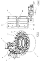
Figure 3 shows a view in larger scale of a printing station. -
Figure 4 shows section IV-IV ofFig.3 . - The above figures illustrate a
printing machine 1 comprising acarousel 2 exhibiting a plurality of object-bearingchucks 3. - The characteristics of the carousel and of the chucks are well known to experts in the sector and are therefore not described in detail.
- The structure of the machine, not illustrated, bears three
printing heads 4 located in succession. - Each of the
heads 4 comprises a structure, not illustrated, which bears aplate bearing roller 41 upon which a whicha-flexographic printing plate 42, of known type, is fitted. - The form-bearing
roller 41 is rotated by a motor, not illustrated, connected to ashaft 411 of theroller 41 by means of an appropriate transmission. - During the rotation of the
roller 41 theflexographic printing plate 42 comes into contact with an inking roller, oranilox roller 5 having known characteristics and being also supported by the structure of the printing head. Aroller 43 bearing atransfer surface 44 made of a more yielding material than that of the flexographic printing plate, such as rubber, is located below the form-bearingroller 41; the extension of the transfer surface is at least equal to that of the flexographic printing plate. - The transfer surface is absolutely smooth and is free of imperfections and surface irregularities.
- In the illustrated example, the
rollers gears - Obviously, other means for coupling can be used.
- The thickness of the flexographic printing plate and the thickness of the transfer surface, like the diameter of the
rollers - One of the
chucks 3 bearing the object to be printed upon 31 is cyclically brought into position below theroller 43 such as to place the surface of the object tangentially with respect to the surface of the transfer surface, with a suitable printing pressure. - The rotations of the chuck are subject to the rotations of the flexographic printing plate thanks to control devices that guarantee reciprocal synchronization in terms of both velocity and running-and-stopping time. These devices can be either mechanical or electrical, and are well-known to experts in the sector; therefore they are not described in detail here.
- With regard to the electrical devices, they are easily deducible from the description of Italian patent application
PR2003A000015 - The distance between the two
rollers - The small deformations of the transfer surface due to the printing pressure exerted by the surface to be printed upon are in fact uniformly distributed over its surface, and cause non-localized and acceptable distortions of the image.
- The yielding nature of the transfer surface guarantees a perfect contact with the object to be printed upon also when the object exhibits surface faults.
- All the aims of the invention are therefore attained; obviosuly the solution herein described can be modified and perfected without its forsaking the ambit of the following claims.
Claims (4)
- A printing head for flexographic printing on thin-walled objects not exhibiting a perfectly smooth surface, the printing head comprising an inking roller (5), which rotates on contact with a flexographic printing plate (42) borne on a printing plate bearing roller (41), characterized in that the printing head comprises a roller (43) bearing a transfer surface (44) which is in rotating contact with the printing plate (42) for receiving the image therefrom and for transferring the image to the printing surface, the transfer surface (44) being a perfectly smooth and faultless surface and being made of a material that is more yielding than a material of which the flexographic printing plate (42) is made.
- The printing head of claim 1, characterized in that the transfer surface (44) is made of rubber.
- The printing head of claim 1, characterized in that the flexographic printing plate bearing roller (41) and the transfer surface roller (43) are reciprocally coupled by means causing the flexographic printing plate bearing roller (41) and the transfer surface bearing roller (43) to rotate in reciprocally-opposite directions at an identical velocity.
- The printing head for the flexographic printing of objects of claim 3, characterized in that the devices rotating the rollers (41,43) in reciprocally-opposite directions and at the identical velocity comprise a pair of gears (410, 430).
Applications Claiming Priority (1)
| Application Number | Priority Date | Filing Date | Title |
|---|---|---|---|
| ITRE2009A000059A IT1398674B1 (en) | 2009-06-15 | 2009-06-15 | FLEXOGRAPHIC PRINTING HEAD |
Publications (2)
| Publication Number | Publication Date |
|---|---|
| EP2263875A1 EP2263875A1 (en) | 2010-12-22 |
| EP2263875B1 true EP2263875B1 (en) | 2012-01-04 |
Family
ID=41376437
Family Applications (1)
| Application Number | Title | Priority Date | Filing Date |
|---|---|---|---|
| EP10165747A Active EP2263875B1 (en) | 2009-06-15 | 2010-06-11 | Flexographic printing head |
Country Status (5)
| Country | Link |
|---|---|
| US (1) | US20110303109A1 (en) |
| EP (1) | EP2263875B1 (en) |
| CN (1) | CN101920593B (en) |
| AT (1) | ATE539884T1 (en) |
| IT (1) | IT1398674B1 (en) |
Family Cites Families (11)
| Publication number | Priority date | Publication date | Assignee | Title |
|---|---|---|---|---|
| US3977318A (en) * | 1974-08-14 | 1976-08-31 | Cohan Alvin M | Machine for simultaneous two image flexographic printing |
| US4035214A (en) * | 1975-07-21 | 1977-07-12 | American Can Company | Total image transfer process |
| US4384518A (en) * | 1980-12-01 | 1983-05-24 | Remington Arms Company, Inc. | Dry offset printer for cylindrical objects |
| US5651316A (en) * | 1995-10-02 | 1997-07-29 | Howard W. DeMoore | Retractable printing/coating unit operable on the plate and blanket cylinders simultaneously from the dampener side of the first printing unit or any consecutive printing unit of any rotary offset printing press |
| JPH10226148A (en) * | 1997-02-17 | 1998-08-25 | Heidelberger Druckmas Ag | Method for multicolor printing of non-absorbable substance |
| DE19714807A1 (en) * | 1997-04-10 | 1998-10-15 | Kba Planeta Ag | Sheet flexo printing machine |
| JP2005014379A (en) * | 2003-06-25 | 2005-01-20 | Asahi Kasei Chemicals Corp | Method and apparatus for manufacturing sleeve printing plate |
| DE102005050989B4 (en) * | 2005-10-25 | 2010-06-10 | Köhler, Friedrich | Method and device for generating color gradient printing |
| JP2008132721A (en) * | 2006-11-29 | 2008-06-12 | Nitto Denko Corp | Cushion sheet for printing machine, printing machine, and printing method |
| CN101279553B (en) * | 2008-05-19 | 2011-04-06 | 深圳市通产丽星股份有限公司 | Rotary flexo press of packaging plastic flexible pipe surface decoration |
| CN101602282A (en) * | 2009-07-02 | 2009-12-16 | 田本杰 | Multifunctional roller type pad printing machine |
-
2009
- 2009-06-15 IT ITRE2009A000059A patent/IT1398674B1/en active
-
2010
- 2010-06-11 EP EP10165747A patent/EP2263875B1/en active Active
- 2010-06-11 AT AT10165747T patent/ATE539884T1/en active
- 2010-06-15 US US12/815,559 patent/US20110303109A1/en not_active Abandoned
- 2010-06-17 CN CN201010206759.7A patent/CN101920593B/en active Active
Also Published As
| Publication number | Publication date |
|---|---|
| EP2263875A1 (en) | 2010-12-22 |
| HK1150815A1 (en) | 2012-01-13 |
| ITRE20090059A1 (en) | 2010-12-16 |
| IT1398674B1 (en) | 2013-03-08 |
| US20110303109A1 (en) | 2011-12-15 |
| CN101920593A (en) | 2010-12-22 |
| CN101920593B (en) | 2014-12-03 |
| ATE539884T1 (en) | 2012-01-15 |
Similar Documents
| Publication | Publication Date | Title |
|---|---|---|
| US6668718B2 (en) | Printing machine with exchangeable ink application means | |
| CN104220260B (en) | Container is decorated | |
| JP6708729B2 (en) | Printer | |
| US20120312179A1 (en) | Intaglio printing press with ink-collecting cylinder | |
| US9713927B2 (en) | Printing press for printing three-dimensional objects | |
| EP0494659B1 (en) | Can coater with improved deactivator responsive to absence of a workpiece | |
| US20210039381A1 (en) | Device for printing on hollow bodies | |
| EP3408100B1 (en) | Device for printing hollow bodies, and method for operating said device | |
| US20110120328A1 (en) | Printing module for use in an offset printing apparatus and offset printing apparatus provided with such a printing module | |
| US7047878B2 (en) | Flexographic printing on containers | |
| US7398730B2 (en) | Printing cylinder support unit, positioning element, printing cylinder provided with positioning element, printing machine provided with printing cylinder support unit, and its use | |
| US20110303109A1 (en) | Flexographic printing head | |
| US5415094A (en) | Apparatus and method for inking of an engraving die utilizing a selectively rotatable inking roller with external ribbing thereon | |
| US4543883A (en) | Apparatus for printing frustoconical articles | |
| US10286647B2 (en) | Processing unit and label printing machine having the processing unit | |
| CN210478122U (en) | Manual installation mechanism of flexible printing plate | |
| MX2010012209A (en) | Rotating clichã pad printer. | |
| US10661590B2 (en) | Method for printing on hollow bodies | |
| HK1150815B (en) | A flexographic printing head | |
| US10773514B2 (en) | Method for operating a device for printing hollow bodies | |
| US20060102021A1 (en) | Printing device for printing conical objects | |
| US11535027B2 (en) | Method and device for printing the respective lateral surface of hollow objects | |
| US10786984B2 (en) | Segment wheel for a device for printing on hollow bodies | |
| CN1970293A (en) | Big stamping roller for planetary type flexible printer | |
| CN120902421A (en) | Pad printing device and transfer printing process |
Legal Events
| Date | Code | Title | Description |
|---|---|---|---|
| PUAI | Public reference made under article 153(3) epc to a published international application that has entered the european phase |
Free format text: ORIGINAL CODE: 0009012 |
|
| AK | Designated contracting states |
Kind code of ref document: A1 Designated state(s): AL AT BE BG CH CY CZ DE DK EE ES FI FR GB GR HR HU IE IS IT LI LT LU LV MC MK MT NL NO PL PT RO SE SI SK SM TR |
|
| AX | Request for extension of the european patent |
Extension state: BA ME RS |
|
| 17P | Request for examination filed |
Effective date: 20110511 |
|
| RAP1 | Party data changed (applicant data changed or rights of an application transferred) |
Owner name: DECOMAC - SOCIETA'A RESPONSABILITA' LIMITATA |
|
| GRAP | Despatch of communication of intention to grant a patent |
Free format text: ORIGINAL CODE: EPIDOSNIGR1 |
|
| RIC1 | Information provided on ipc code assigned before grant |
Ipc: B41F 5/22 20060101AFI20110624BHEP Ipc: B41F 17/22 20060101ALI20110624BHEP Ipc: B41N 10/00 20060101ALI20110624BHEP Ipc: B41F 13/193 20060101ALI20110624BHEP Ipc: B41F 5/24 20060101ALI20110624BHEP |
|
| GRAS | Grant fee paid |
Free format text: ORIGINAL CODE: EPIDOSNIGR3 |
|
| GRAA | (expected) grant |
Free format text: ORIGINAL CODE: 0009210 |
|
| AK | Designated contracting states |
Kind code of ref document: B1 Designated state(s): AL AT BE BG CH CY CZ DE DK EE ES FI FR GB GR HR HU IE IS IT LI LT LU LV MC MK MT NL NO PL PT RO SE SI SK SM TR |
|
| REG | Reference to a national code |
Ref country code: GB Ref legal event code: FG4D |
|
| REG | Reference to a national code |
Ref country code: CH Ref legal event code: EP |
|
| REG | Reference to a national code |
Ref country code: AT Ref legal event code: REF Ref document number: 539884 Country of ref document: AT Kind code of ref document: T Effective date: 20120115 |
|
| REG | Reference to a national code |
Ref country code: IE Ref legal event code: FG4D |
|
| REG | Reference to a national code |
Ref country code: DE Ref legal event code: R096 Ref document number: 602010000620 Country of ref document: DE Effective date: 20120308 |
|
| REG | Reference to a national code |
Ref country code: CH Ref legal event code: NV Representative=s name: ISLER & PEDRAZZINI AG |
|
| REG | Reference to a national code |
Ref country code: NL Ref legal event code: T3 |
|
| PG25 | Lapsed in a contracting state [announced via postgrant information from national office to epo] |
Ref country code: SI Free format text: LAPSE BECAUSE OF FAILURE TO SUBMIT A TRANSLATION OF THE DESCRIPTION OR TO PAY THE FEE WITHIN THE PRESCRIBED TIME-LIMIT Effective date: 20120104 |
|
| LTIE | Lt: invalidation of european patent or patent extension |
Effective date: 20120104 |
|
| PG25 | Lapsed in a contracting state [announced via postgrant information from national office to epo] |
Ref country code: NO Free format text: LAPSE BECAUSE OF FAILURE TO SUBMIT A TRANSLATION OF THE DESCRIPTION OR TO PAY THE FEE WITHIN THE PRESCRIBED TIME-LIMIT Effective date: 20120404 Ref country code: LT Free format text: LAPSE BECAUSE OF FAILURE TO SUBMIT A TRANSLATION OF THE DESCRIPTION OR TO PAY THE FEE WITHIN THE PRESCRIBED TIME-LIMIT Effective date: 20120104 Ref country code: BE Free format text: LAPSE BECAUSE OF FAILURE TO SUBMIT A TRANSLATION OF THE DESCRIPTION OR TO PAY THE FEE WITHIN THE PRESCRIBED TIME-LIMIT Effective date: 20120104 Ref country code: IS Free format text: LAPSE BECAUSE OF FAILURE TO SUBMIT A TRANSLATION OF THE DESCRIPTION OR TO PAY THE FEE WITHIN THE PRESCRIBED TIME-LIMIT Effective date: 20120504 Ref country code: HR Free format text: LAPSE BECAUSE OF FAILURE TO SUBMIT A TRANSLATION OF THE DESCRIPTION OR TO PAY THE FEE WITHIN THE PRESCRIBED TIME-LIMIT Effective date: 20120104 Ref country code: BG Free format text: LAPSE BECAUSE OF FAILURE TO SUBMIT A TRANSLATION OF THE DESCRIPTION OR TO PAY THE FEE WITHIN THE PRESCRIBED TIME-LIMIT Effective date: 20120404 |
|
| PG25 | Lapsed in a contracting state [announced via postgrant information from national office to epo] |
Ref country code: FI Free format text: LAPSE BECAUSE OF FAILURE TO SUBMIT A TRANSLATION OF THE DESCRIPTION OR TO PAY THE FEE WITHIN THE PRESCRIBED TIME-LIMIT Effective date: 20120104 Ref country code: PL Free format text: LAPSE BECAUSE OF FAILURE TO SUBMIT A TRANSLATION OF THE DESCRIPTION OR TO PAY THE FEE WITHIN THE PRESCRIBED TIME-LIMIT Effective date: 20120104 Ref country code: LV Free format text: LAPSE BECAUSE OF FAILURE TO SUBMIT A TRANSLATION OF THE DESCRIPTION OR TO PAY THE FEE WITHIN THE PRESCRIBED TIME-LIMIT Effective date: 20120104 Ref country code: PT Free format text: LAPSE BECAUSE OF FAILURE TO SUBMIT A TRANSLATION OF THE DESCRIPTION OR TO PAY THE FEE WITHIN THE PRESCRIBED TIME-LIMIT Effective date: 20120504 Ref country code: GR Free format text: LAPSE BECAUSE OF FAILURE TO SUBMIT A TRANSLATION OF THE DESCRIPTION OR TO PAY THE FEE WITHIN THE PRESCRIBED TIME-LIMIT Effective date: 20120405 |
|
| PG25 | Lapsed in a contracting state [announced via postgrant information from national office to epo] |
Ref country code: CY Free format text: LAPSE BECAUSE OF FAILURE TO SUBMIT A TRANSLATION OF THE DESCRIPTION OR TO PAY THE FEE WITHIN THE PRESCRIBED TIME-LIMIT Effective date: 20120104 |
|
| PG25 | Lapsed in a contracting state [announced via postgrant information from national office to epo] |
Ref country code: RO Free format text: LAPSE BECAUSE OF FAILURE TO SUBMIT A TRANSLATION OF THE DESCRIPTION OR TO PAY THE FEE WITHIN THE PRESCRIBED TIME-LIMIT Effective date: 20120104 Ref country code: EE Free format text: LAPSE BECAUSE OF FAILURE TO SUBMIT A TRANSLATION OF THE DESCRIPTION OR TO PAY THE FEE WITHIN THE PRESCRIBED TIME-LIMIT Effective date: 20120104 Ref country code: SE Free format text: LAPSE BECAUSE OF FAILURE TO SUBMIT A TRANSLATION OF THE DESCRIPTION OR TO PAY THE FEE WITHIN THE PRESCRIBED TIME-LIMIT Effective date: 20120104 Ref country code: CZ Free format text: LAPSE BECAUSE OF FAILURE TO SUBMIT A TRANSLATION OF THE DESCRIPTION OR TO PAY THE FEE WITHIN THE PRESCRIBED TIME-LIMIT Effective date: 20120104 Ref country code: DK Free format text: LAPSE BECAUSE OF FAILURE TO SUBMIT A TRANSLATION OF THE DESCRIPTION OR TO PAY THE FEE WITHIN THE PRESCRIBED TIME-LIMIT Effective date: 20120104 |
|
| PLBE | No opposition filed within time limit |
Free format text: ORIGINAL CODE: 0009261 |
|
| STAA | Information on the status of an ep patent application or granted ep patent |
Free format text: STATUS: NO OPPOSITION FILED WITHIN TIME LIMIT |
|
| PG25 | Lapsed in a contracting state [announced via postgrant information from national office to epo] |
Ref country code: SK Free format text: LAPSE BECAUSE OF FAILURE TO SUBMIT A TRANSLATION OF THE DESCRIPTION OR TO PAY THE FEE WITHIN THE PRESCRIBED TIME-LIMIT Effective date: 20120104 |
|
| 26N | No opposition filed |
Effective date: 20121005 |
|
| PG25 | Lapsed in a contracting state [announced via postgrant information from national office to epo] |
Ref country code: MC Free format text: LAPSE BECAUSE OF NON-PAYMENT OF DUE FEES Effective date: 20120630 |
|
| REG | Reference to a national code |
Ref country code: DE Ref legal event code: R097 Ref document number: 602010000620 Country of ref document: DE Effective date: 20121005 |
|
| PG25 | Lapsed in a contracting state [announced via postgrant information from national office to epo] |
Ref country code: MK Free format text: LAPSE BECAUSE OF FAILURE TO SUBMIT A TRANSLATION OF THE DESCRIPTION OR TO PAY THE FEE WITHIN THE PRESCRIBED TIME-LIMIT Effective date: 20120104 |
|
| REG | Reference to a national code |
Ref country code: IE Ref legal event code: MM4A |
|
| PG25 | Lapsed in a contracting state [announced via postgrant information from national office to epo] |
Ref country code: ES Free format text: LAPSE BECAUSE OF FAILURE TO SUBMIT A TRANSLATION OF THE DESCRIPTION OR TO PAY THE FEE WITHIN THE PRESCRIBED TIME-LIMIT Effective date: 20120415 Ref country code: IE Free format text: LAPSE BECAUSE OF NON-PAYMENT OF DUE FEES Effective date: 20120611 |
|
| PG25 | Lapsed in a contracting state [announced via postgrant information from national office to epo] |
Ref country code: MT Free format text: LAPSE BECAUSE OF FAILURE TO SUBMIT A TRANSLATION OF THE DESCRIPTION OR TO PAY THE FEE WITHIN THE PRESCRIBED TIME-LIMIT Effective date: 20120104 |
|
| PG25 | Lapsed in a contracting state [announced via postgrant information from national office to epo] |
Ref country code: AL Free format text: LAPSE BECAUSE OF FAILURE TO SUBMIT A TRANSLATION OF THE DESCRIPTION OR TO PAY THE FEE WITHIN THE PRESCRIBED TIME-LIMIT Effective date: 20120104 |
|
| PG25 | Lapsed in a contracting state [announced via postgrant information from national office to epo] |
Ref country code: TR Free format text: LAPSE BECAUSE OF FAILURE TO SUBMIT A TRANSLATION OF THE DESCRIPTION OR TO PAY THE FEE WITHIN THE PRESCRIBED TIME-LIMIT Effective date: 20120104 |
|
| PG25 | Lapsed in a contracting state [announced via postgrant information from national office to epo] |
Ref country code: LU Free format text: LAPSE BECAUSE OF NON-PAYMENT OF DUE FEES Effective date: 20120611 Ref country code: SM Free format text: LAPSE BECAUSE OF FAILURE TO SUBMIT A TRANSLATION OF THE DESCRIPTION OR TO PAY THE FEE WITHIN THE PRESCRIBED TIME-LIMIT Effective date: 20120104 |
|
| PG25 | Lapsed in a contracting state [announced via postgrant information from national office to epo] |
Ref country code: HU Free format text: LAPSE BECAUSE OF FAILURE TO SUBMIT A TRANSLATION OF THE DESCRIPTION OR TO PAY THE FEE WITHIN THE PRESCRIBED TIME-LIMIT Effective date: 20100611 |
|
| REG | Reference to a national code |
Ref country code: FR Ref legal event code: PLFP Year of fee payment: 7 |
|
| REG | Reference to a national code |
Ref country code: FR Ref legal event code: PLFP Year of fee payment: 8 |
|
| REG | Reference to a national code |
Ref country code: FR Ref legal event code: PLFP Year of fee payment: 9 |
|
| PGFP | Annual fee paid to national office [announced via postgrant information from national office to epo] |
Ref country code: DE Payment date: 20250627 Year of fee payment: 16 |
|
| PGFP | Annual fee paid to national office [announced via postgrant information from national office to epo] |
Ref country code: GB Payment date: 20250627 Year of fee payment: 16 |
|
| PGFP | Annual fee paid to national office [announced via postgrant information from national office to epo] |
Ref country code: NL Payment date: 20250626 Year of fee payment: 16 Ref country code: IT Payment date: 20250428 Year of fee payment: 16 |
|
| PGFP | Annual fee paid to national office [announced via postgrant information from national office to epo] |
Ref country code: FR Payment date: 20250625 Year of fee payment: 16 |
|
| PGFP | Annual fee paid to national office [announced via postgrant information from national office to epo] |
Ref country code: AT Payment date: 20250521 Year of fee payment: 16 |
|
| PGFP | Annual fee paid to national office [announced via postgrant information from national office to epo] |
Ref country code: CH Payment date: 20250701 Year of fee payment: 16 |