EP2263865A2 - Copper grid repair technique for ligthning strike protection - Google Patents
Copper grid repair technique for ligthning strike protection Download PDFInfo
- Publication number
- EP2263865A2 EP2263865A2 EP10181387A EP10181387A EP2263865A2 EP 2263865 A2 EP2263865 A2 EP 2263865A2 EP 10181387 A EP10181387 A EP 10181387A EP 10181387 A EP10181387 A EP 10181387A EP 2263865 A2 EP2263865 A2 EP 2263865A2
- Authority
- EP
- European Patent Office
- Prior art keywords
- electrically conductive
- conductive layer
- patch
- section
- curing
- Prior art date
- Legal status (The legal status is an assumption and is not a legal conclusion. Google has not performed a legal analysis and makes no representation as to the accuracy of the status listed.)
- Granted
Links
Images

Classifications
-
- B—PERFORMING OPERATIONS; TRANSPORTING
- B29—WORKING OF PLASTICS; WORKING OF SUBSTANCES IN A PLASTIC STATE IN GENERAL
- B29C—SHAPING OR JOINING OF PLASTICS; SHAPING OF MATERIAL IN A PLASTIC STATE, NOT OTHERWISE PROVIDED FOR; AFTER-TREATMENT OF THE SHAPED PRODUCTS, e.g. REPAIRING
- B29C73/00—Repairing of articles made from plastics or substances in a plastic state, e.g. of articles shaped or produced by using techniques covered by this subclass or subclass B29D
- B29C73/04—Repairing of articles made from plastics or substances in a plastic state, e.g. of articles shaped or produced by using techniques covered by this subclass or subclass B29D using preformed elements
- B29C73/10—Repairing of articles made from plastics or substances in a plastic state, e.g. of articles shaped or produced by using techniques covered by this subclass or subclass B29D using preformed elements using patches sealing on the surface of the article
-
- B—PERFORMING OPERATIONS; TRANSPORTING
- B64—AIRCRAFT; AVIATION; COSMONAUTICS
- B64D—EQUIPMENT FOR FITTING IN OR TO AIRCRAFT; FLIGHT SUITS; PARACHUTES; ARRANGEMENT OR MOUNTING OF POWER PLANTS OR PROPULSION TRANSMISSIONS IN AIRCRAFT
- B64D45/00—Aircraft indicators or protectors not otherwise provided for
- B64D45/02—Lightning protectors; Static dischargers
-
- B—PERFORMING OPERATIONS; TRANSPORTING
- B64—AIRCRAFT; AVIATION; COSMONAUTICS
- B64F—GROUND OR AIRCRAFT-CARRIER-DECK INSTALLATIONS SPECIALLY ADAPTED FOR USE IN CONNECTION WITH AIRCRAFT; DESIGNING, MANUFACTURING, ASSEMBLING, CLEANING, MAINTAINING OR REPAIRING AIRCRAFT, NOT OTHERWISE PROVIDED FOR; HANDLING, TRANSPORTING, TESTING OR INSPECTING AIRCRAFT COMPONENTS, NOT OTHERWISE PROVIDED FOR
- B64F5/00—Designing, manufacturing, assembling, cleaning, maintaining or repairing aircraft, not otherwise provided for; Handling, transporting, testing or inspecting aircraft components, not otherwise provided for
- B64F5/40—Maintaining or repairing aircraft
-
- B—PERFORMING OPERATIONS; TRANSPORTING
- B29—WORKING OF PLASTICS; WORKING OF SUBSTANCES IN A PLASTIC STATE IN GENERAL
- B29L—INDEXING SCHEME ASSOCIATED WITH SUBCLASS B29C, RELATING TO PARTICULAR ARTICLES
- B29L2031/00—Other particular articles
- B29L2031/30—Vehicles, e.g. ships or aircraft, or body parts thereof
- B29L2031/3076—Aircrafts
- B29L2031/3085—Wings
Definitions
- the present invention generally relates to aircraft lightning protection techniques and more specifically to a copper grid repair technique for composite aircraft skin panels.
- CFRP carbon fiber reinforced plastic
- a lightning strike to an aircraft causes a high electric current, which may typically be of the order of 100,000 amps, to flow through the aircraft frame.
- a high electric current which may typically be of the order of 100,000 amps
- the carbon fiber plies act as very high resistance conductors and the resin between the plies acts as highly capacitive dielectric layers so that lightning striking the carbon fiber composite results in an increasing potential difference produced across the ply structure but no readily available electrically conductive path for discharging the current.
- the current therefore tends to concentrate at the fasteners between the skin panels and the aircraft substructure, since the fasteners are generally made of highly conductive alloys for strength. When the lightning energy is unable to dissipate at a fast enough rate, arcing and dangerous sparks are likely to occur.
- One known approach to reduce the effect of lightning strikes on non-metallic structures is to apply, by flame spraying or plating, a conductive layer such as aluminum to the outer surface of the skin panels.
- the problem with flame spraying or plating is that they are secondary operations used to apply the conductive layer to the already assembled structure.
- the protective conductive layer also adds mass without contributing to the strength of the assembled structure, is vulnerable to environmental damage, and is difficult to maintain. The production and maintenance of such an arrangement is thus clearly expensive.
- the proposed system does not address the need for repairing the copper grid system after a lightning strike or after other mechanical damage.
- the electrical continuity of the electrically conductive layer must be reestablished to provide proper lightning strike protection.
- the present invention provides a method for reestablishing the electrical continuity of an electrically conductive layer, preferably a copper foil grid that includes strips of copper foil coupled to and centered around fasteners located in a fastener line on the composite aircraft wing, that has been previously damaged mechanically or by a lightning strike.
- the present invention utilizes a copper patch and a specialized adhesive to replace the damaged section of the electrically conductive layer.
- the repair is performed by first removing any surfacers (paints, primers, fiberglass layers) as well as a portion of the electrically conductive layer to create an opening to the underlying composite skin. Any fasteners in the immediate area of the damage are also removed.
- a copper patch consisting of an unsupported film adhesive and a copper foil strip is then bonded and cured over to the composite skin within the opening.
- One ply of resin-impregnated fiberglass is then wet-layed over the surface of the copper patch and cured. Holes are drilled through the cured fiberglass plies and copper patch and the fasteners are reinstalled. This allows the fasteners to be recoupled to the underlying composite skin and copper foil.
- the primer and paint are then reapplied and cured over the fiberglass to complete the repair.
- the repair is performed by first removing any surfacers (paints, primers, fiberglass layers) as well as a portion of the electrically conductive layer to create an opening to the underlying composite skin. Any fasteners in the immediate area of the damage are also removed. A copper patch consisting of an unsupported adhesive film and a copper foil strip is then placed within the opening such that the adhesive is contained between the copper foil strip and the underlying composite skin. One ply of a fiberglass prepreg material is then applied over the copper patch. The prepreg and film adhesive are then preferably cured simultaneously in a single step under heat and pressure, although alternatively they may be cured individually after application. Holes are drilled through the fiberglass layer and copper patch and the fasteners are reinstalled. This allows the fasteners to be recoupled to the underlying composite skin and copper skin. The primer and paint are then reapplied and cured over the fiberglass prepreg to complete the repair.
- any surfacers paints, primers, fiberglass layers
- the techniques of the preferred embodiments described above are relatively simple and available to make quick and cost-effective repairs to commercial aircraft already in service.
- This repair helps to maintain the integrity of the lightning prevention system to help divert lightning currents away from the fuel tank substructures by providing a lower resistance path along the wing's surface.
- the repair also maintains the reduction of current density at the target fasteners by allowing current sharing to the neighboring fasteners due to the reduced parallel path resistance created by the copper foil.
- the repairs allow the commercial aircraft to be placed back in service quickly and at a minimum of time and expense.
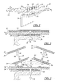
- Figure 1 is a perspective view of a pristine composite wing structure of a commercial airplane
- Figure 2 is a section view of a portion of Figure 1 taken along line 2-2;
- Figure 3 is a section view of a general method for repairing the damaged portion of the wing structure of Figure 1 in accordance with the general principals of a preferred embodiment of the present invention
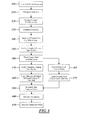
- Figure 4 is a logic flow diagram for repairing a wing structure of Figure 1 in accordance with one preferred embodiment of the present invention
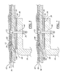
- Figure 5 is a section view of a repaired wing structure of Figure 1 repaired in accordance with the logic flow diagram of Figure 4 ;
- Figure 6 is a logic flow diagram for repairing a wing structure of Figure 1 in accordance with another preferred embodiment of the present invention.
- Figure 7 is a section view of a repaired wing structure of Figure 1 repaired in accordance with the logic flow diagram of Figure 6 .
- FIG. 1 and 2 a section and perspective view of a portion of a wing structure 10 of a commercial airplane showing a plurality of fasteners 12 is shown securing a skin panel 14 of an aircraft structure to an inner substructure 16, or spar 16, comprising the wall of a fuel tank.
- the skin panel 14 and the spar 16 are made of carbon fiber composite material of low weight and high strength and stiffness formed by conventional methods well known in the art.
- the skin panel 14 is formed from 34 plies of an aircraft quality, machine lay-up structural carbon fiber/epoxy tape laid in a 50/40/10 orientation and having an overall thickness approximately 0.2516 inches
- the spar 16 consists of 44 plies of a hand lay-up version of aircraft quality, structural carbon fiber/epoxy tape laid in a 25/50/25 layup and having an overall thickness of about 0.3256 inches. Both the skin panel 14 and spar 16 are primed on both the tool and bag side prior to installation.
- the fastener 12 is made of metal such as titanium and comprises a bolt 18, preferably a Hi-Lok bolt (or e.g., a Lockbolt, Eddiebolt or Sleeved Lockbolt) with a preload shear, having a beveled head 20, which is countersunk into a correspondingly shaped opening 22 in the skin panel 14, and a shank 24 (0.25 inch diameter bare titanium with a 100 degree shear head), which passes through the skin panel 14 and spar 16 to be secured by a metallic nut 26 engaging the spar 16.
- a sealant (not shown) is introduced to the shank 24 prior to installation into the spar 16 and skin panel 14.
- the shim 28 is sealed to the panel 14 and spar 16 using a fay sealant 30.
- the fastener 12 also secures an electrically conductive layer, preferably a copper foil grid 32 in the form of a plurality of strips 33, and a fiberglass ply layer 34, respectively, to the skin panel 14.
- the grid 32 is therefore considered an integral part of the skin 14.
- the aircraft wing structure 10 is coated with one or more primer coats (here shown as a single layer of primer 36) over the outer surface of the skin panel 14, covering both the fiberglass ply layer 34 and the head 20 of the fastener 12, which is flush with the outer surface of the grid 32.
- One or more layers 42 of paint are then applied over the entire outer surface of the primer 36.
- Each strip 33 of the copper foil grid 32 is a 0.0027 inch thick, 2 ounce/ft 2 copper foil such as IPC-4562/Cu-E-2-2-D-S-2 copper foil, which is manufactured by Gould Electronics, Inc. of Chandler, Arizona.
- the strips 33 are each individually centered along a respective fastener line 35 and are about 3.6 inches wide for a single fastener 12. While not shown in the present illustrations, the strips 33 may overlap depending upon their respective relative location along the spar 16 and skin panel 14.
- the copper foil grid 32 has sufficient electrical conductivity to meet or exceed IPC-4562 grade specifications to ensure a safe conductive path to divert much of the electric current, generated by lightning strikes in use, away from each respective fastener 12 along a fastener line 35.
- the fiberglass ply layer 34 is preferably an epoxy-prepreg material formed with a Style 120 E-glass and a 250-degree Fahrenheit cure thermosetting epoxy resin.
- a wet lay-up of a similar glass weave (E-glass, Style 108) in a 250-degree Fahrenheit cure thermosetting epoxy resin may also be utilized.
- the primer 36 consists of a conventional thermosetting epoxy-based fuel tank primer well known to those of ordinary skill in the art in the aerospace industry.
- the primer 36 is applied in one or more coats to a dry film thickness of between about 0.5 and 0.9 mils.
- the primer 36 is air dried for between about 4 hours prior to applications of the overlying paint layers 42.
- the paint layer, or layers 42 preferably are formed a conventional, aerospace grade polyurethane enamel that is also well known to those of ordinary skill in the art in the aerospace industry.
- This polyurethane enamel is preferably applied as a single layer of approximately 2 mil +/- 0.1 dry thickness over the previously dried primer 36. If more than about 48 hours has passed since application of the primer 36, it is required to reactivate the surface of the primer 36 by wiping the surface with a solvent such as isopropyl alcohol prior to applying the paint 42.
- the paint 42 is air dried for between about 4 hours and 7 days to ensure complete curing.
- the paint 42 and primer 36 layers are first removed from the damaged area 50 of the wing structure 10, plus two inches radially at a minimum, with a 150-grit or finer abrasive, ensuring that all of the paint 42 and primer 36 are removed without affecting the underlying fiberglass layer 34.
- Step 110 the composite ply fiberglass layers 34 are removed via a sanding process.
- a low or high temperature pressure tape is first applied along the outline of the area to be sanded.
- the sanding is performed either manually or mechanically using various grits of sandpaper, and diamond or carbide cutting wheels. The sanding is done in either a circular, oblong or semicircular patter based on the defect configuration and location.
- the area is then finish sanded with 240-grit or finer sandpaper.
- the fiberglass ply 34 remaining is then unmasked and solvent washed.
- the sanded area is then wiped dry.
- Step 120 any damaged copper from a strip or strips 33 are carefully removed without impairing the underlying carbon fiber skin 14.
- Figure 3 one damaged strip 33 is illustrated.
- Undamaged copper foil 33B from each respective damaged strip 33 is maintained in its location on top of the carbon fiber skin 14 around the repair area 54.
- the fasteners 12 are removed in the immediate area of the damaged area 50, leaving fastener holes 13 open.
- the fasteners 12 may or may not have been damaged by a lightning strike or mechanical issue.
- the fastener holes 13 are then plugged with a 1 ⁇ 4 inch polytetrafluoroethylene plug. Milled glass and a 150-degree Fahrenheit curing thermosetting epoxy resin are introduced around the plug to fill the countersink around the fastener hole 13. Localized heat of sufficient temperature is introduced near the fastener hole 13 to cure the epoxy resin.
- Step 140 a section of pristine copper foil 52 is cut to fit the repair area 54 with an overlap 56 over the periphery 58 of the underlying remaining copper foil strip 33B surrounding the repair area 54. Typically, this overlap 56 is between one-half and one inch.
- the copper foil section 52 is formed from the same material and thickness as the original copper strip 33 (preferably Gould IPC-4562/ Cu-E-2-2-D-S-2 (0.0027 inches thick, 2 oz.)).
- the copper foil section 52 is rinsed with isopropyl alcohol, without sanding or abrasion, to prepare the copper foil section 52 for subsequent bonding to an epoxy film adhesive 60.
- an epoxy film adhesive 60 is cut to the same size as the copper foil section 52 and coupled to the underside of the copper foil 52 to form a copper patch 53.
- the epoxy film adhesive 60 is an unsupported adhesive material, meaning that there are no carrier materials utilized.
- the epoxy film adhesive 60 is about 0.005 inches thick and a nominal weight of about 0.030 pounds per square foot.
- One preferred unsupported modified epoxy film adhesive 60 is FM300-2U, a 250 degree Fahrenheit cure thermosetting epoxy adhesive available from Cytec Engineered Materials of West Patterson, New Jersey.
- a 350-degree Fahrenheit curing thermosetting epoxy adhesive film 60 may be utilized.
- One such 350-degree Fahrenheit curing thermosetting epoxy adhesive film 60 is AF555 Grade 15U, available from Minnesota Mining & Manufacturing (3M) of St. Paul, Minnesota.
- the copper patch 53 is introduced to the repair area 54 such that the film adhesive 60 covers the underlying skin 14 and overlaps a portion of the outer periphery 58 of the remaining copper strip 33B and such that the copper foil section 52 covers the entire portion of the film adhesive 60.
- this is done by first introducing the film adhesive 60 over the skin 14 and overlapping the remaining strip 33B and then introducing the copper foil section 52 onto the film adhesive 60.
- the film adhesive 60 may first be bonded to the copper foil section 52 to form the patch 53, and the patch is then subsequently introduced as a single unit onto the skin 14 with the adhesive side 60 contacting the skin 14.
- Step 170 the copper foil section 52 is bonded onto the remaining underlying copper strip 33B over the repair area 54 in the overlap 56 by curing the epoxy component of the film adhesive 60 to the copper foil section 52, the outer periphery 58 of the copper strip 33B and to the underlying skin 14.
- a temperature of about 255 +/- 10 degrees Fahrenheit for about 90 minutes using a vacuum bag technique and a heat blanket is utilized.
- a vacuum bag is used and maintained at a negative pressure of about 25 in-Hg, while the bag side temperature is ramped up in 5-degree Fahrenheit increments until a heat blanket temperature of about 255 degrees Fahrenheit is reached.
- thermocouples are preferably positioned against the skin 14 next to the spar 16 and on the skin side of the spar 16 prior to the curing step.
- thermosetting epoxy adhesive For a 350-degree Fahrenheit cure thermosetting epoxy adhesive, a temperature of about 355 +/- 10 degrees Fahrenheit for about 90 minutes using a vacuum bag technique and a heat blanket is utilized. Most preferably, a vacuum bag is used and maintained at a negative pressure of about 25 in-Hg, while the bag side temperature is ramped up in 5-degree Fahrenheit increments until a heat blanket temperature of about 355 degrees Fahrenheit is reached. The heat blanket temperature is then maintained at 355 degrees Fahrenheit for about 90 minutes to ensure complete cure. The heat blanket temperature is then reduced slowly to 140 degrees Fahrenheit before the vacuum bag is removed. The heat blanket is removed after the vacuum bag. To ensure proper temperature control, thermocouples (not shown) are preferably positioned against the skin 14 next to the spar 16 and on the skin side of the spar 16 prior to the curing step.
- Step 180 a layer of a resin-impregnated fiberglass fabric 62 is wet-layed over the cured copper patch 53 with a 0.5-inch overlap over the outer periphery of the patch 53.
- a solid parting film at least four inches larger in every direction than the piece of fiberglass fabric being impregnated is first laid on a flat surface.
- a layer of a 150-degree Fahrenheit curing thermosetting epoxy resin is applied to the parting film.
- a layer of E-glass fiberglass fabric is applied onto the epoxy resin layer.
- Another layer of epoxy resin is then applied over the fiberglass fabric.
- the preferred ratio of resin to fiberglass fabric is between about 1 and 1.5 ounces of resin per ounce of fabric.
- a second layer of parting film is applied onto the second resin layer.
- the resin of the resin layers is uniformly impregnated within the glass fabric using a roller, squeegee or similar device. Most preferably, a vacuum bag is placed over the assembly to facilitate impregnation.
- the ply 62 is wet-layed onto the copper patch 53.
- the parting film is removed from one side of the ply 62 and the exposed side is layed onto the copper foil section 52.
- the second piece of parting film of the ply 62 is then removed from the surface opposite the patch 53.
- the layer 62 is then vacuum bagged to ensure complete infiltration of the additional epoxy resin within the glass fabric 62.
- a heat blanket is coupled to the ply 62 and the epoxy component of the fiberglass fabric 62 layer is cured under vacuum with a heat blanket temperature of about 200 +/- 10 degrees Fahrenheit for about 220 minutes. The heat blanket is then removed.
- Step 190 new fastener holes 64 are drilled through the cured fiberglass layer 62, the copper patch 53, skin 14, and through into the underlying shim 28 and spar 16.
- the new fastener holes 64 are inspected to verify location and to confirm shape and size.
- Step 200 new and pristine fasteners 12 are wet-installed by conventional techniques through fastener holes 64, which include applying a full faying surface sealant to the shank 24 not in the threaded area.
- the fasteners 12 are torqued within the working life of the sealant. Excess sealant is removed after the installation of the fasteners 12 have been verified for proper grip length; head flushness, torque value and sealant squeeze out.
- Step 210 the layers of primer 32 and paint 42 are reapplied over the fiberglass ply 62 and fasteners 12 in a method similar to that described above in forming the original painted and primed surface.
- the resultant repair is shown in Figure 5 .
- Steps 300-360 are first performed utilizing the same materials and in exactly the same manner as Steps 100-160 above.
- a layer of fiberglass prepreg 80 is applied onto the applied copper patch 53.
- the fiberglass prepreg 80 consists of E-glass fabric preimpregnated with either a 250- or 350-degree Fahrenheit curing thermosetting epoxy resin.
- the fiberglass prepreg 80 is cut to fit with a 0.5-inch overlap over the periphery of the repaired area 54.
- Step 380 the epoxy components of the fiberglass prepreg 80 and epoxy film adhesive 60 of the patch 53, are simultaneously cured using a vacuum bag technique and a heat blanket when the curing temperatures of the unsupported film adhesive and the epoxy component of the prepreg 80 are the same.
- a temperature of about 255 +/- 10 degrees Fahrenheit for about 2 hours using a vacuum bag technique and a heat blanket is utilized.
- a temperature of about 355 +/- 10 degrees Fahrenheit for about 2 hours using a vacuum bag technique and a heat blanket is utilized.
- the heat blanket and vacuum are then removed and the cured layers of both the prepreg 80 and adhesive 60 are cooled.
- Step 365 and 375 when the curing temperature of the unsupported film adhesive 60 is different than the curing temperature of the epoxy component of the prepreg 80, a different method is utilized.
- Step 365 the unsupported film adhesive 60 is cured as in the method of Step 170 above to bond the copper foil section 52 to the skin 14.
- Step 375 the epoxy prepreg 80 is layed onto the copper foil section 52 and separately cured.
- a temperature of about 255 +/- 10 degrees Fahrenheit for about 2 hours using a vacuum bag technique and a heat blanket is utilized.
- a temperature of about 355 +/- 10 degrees Fahrenheit for about 2 hours using a vacuum bag technique and a heat blanket is utilized.
- the cured layers of both the prepreg 80 and adhesive 60 are then cooled.
- Step 390 proceeding either from Step 375 or 380,new fastener holes 64 are drilled through the fiberglass prepreg 80, the copper foil section 52, skin 14, and through into the underlying shim 28 and spar 16 as described above in Step 190.
- Step 400 fasteners 12 are reinserted and secured substantially as describe above in Step 200.
- Step 410 the layers of primer 36 and paint 42 are reapplied and cured onto the fiberglass prepreg 80 and cover the fasteners 12 using techniques described above in Step 210.
- the resultant repaired wing structure 10 is best illustrated in Figure 7 .
- the present invention thus describes two preferred methods for repairing composite wing structures 10 damaged in lightning strikes or by some other mechanical means.
- This repair helps to maintain the integrity of the lightning prevention system to help divert lightning currents away from the fuel tank substructures by providing a lower resistance path along the wing's surface.
- the repair also maintains the reduction of current density at the target fasteners by allowing current sharing to the neighboring fasteners due to the reduced parallel path resistance created by the copper foil.
- the methods of the preferred embodiments are relatively simple and cost effective, in that that utilize standard composite repair materials and can be performed easily in a relatively short amount of time. This limits the amount of down time for repair of commercial aircraft, therein allowing the aircraft to spend more time transporting passengers and cargo.
Landscapes
- Engineering & Computer Science (AREA)
- Aviation & Aerospace Engineering (AREA)
- Mechanical Engineering (AREA)
- Manufacturing & Machinery (AREA)
- Transportation (AREA)
- Laminated Bodies (AREA)
- Conductive Materials (AREA)
- Compositions Of Oxide Ceramics (AREA)
- Moulding By Coating Moulds (AREA)
Abstract
Description
- The present invention generally relates to aircraft lightning protection techniques and more specifically to a copper grid repair technique for composite aircraft skin panels.
- The use of carbon fiber reinforced plastic ("CFRP") materials, otherwise known as carbon fiber composites, for structural members is increasing in commercial airplanes because of the higher strength-to-weight and stiffness-to-weight ratios afforded by carbon fiber composites as compared to traditional aluminum structures.
- A lightning strike to an aircraft causes a high electric current, which may typically be of the order of 100,000 amps, to flow through the aircraft frame. In a carbon fiber composite structure, which is approximately 2000 times more resistive than aluminum, the carbon fiber plies act as very high resistance conductors and the resin between the plies acts as highly capacitive dielectric layers so that lightning striking the carbon fiber composite results in an increasing potential difference produced across the ply structure but no readily available electrically conductive path for discharging the current. The current therefore tends to concentrate at the fasteners between the skin panels and the aircraft substructure, since the fasteners are generally made of highly conductive alloys for strength. When the lightning energy is unable to dissipate at a fast enough rate, arcing and dangerous sparks are likely to occur.
- This is a considerable problem, especially when the substructure is the wall of a fuel tank and arcing carries the highly dangerous risk of ejecting sparks, molten material and hot gasses into the fuel tank.
- One known approach to reduce the effect of lightning strikes on non-metallic structures is to apply, by flame spraying or plating, a conductive layer such as aluminum to the outer surface of the skin panels. The problem with flame spraying or plating is that they are secondary operations used to apply the conductive layer to the already assembled structure. In addition, it is difficult to achieve a satisfactory electrical bond using either of these processes. The protective conductive layer also adds mass without contributing to the strength of the assembled structure, is vulnerable to environmental damage, and is difficult to maintain. The production and maintenance of such an arrangement is thus clearly expensive.
- Another known approach to reduce the effect of lightning strikes on non-metallic surfaces is to install a conductive woven screen or foil to the outer surface of the skin panels. However, the use of woven screens or foils requires the use of an additional ply of fiberglass when the non-metallic structure is carbon to electrically isolate the carbon layer from the metal to prevent corrosion that also adds non-structural weight.
- Yet another approach is to employ various special designs of fastener, for example as disclosed in
U.S. Patent No. 4,891,732 . The fasteners disclosed in these patents employ a beveled head for countersinking into the surface of the skin panel into intimate contact therewith, and a nut for securing the fastener in place, which nut is designed to transmit electric current safely to the substructure such that arcing will not occur. Again, this approach to the problem of arcing is expensive because of the need for special fastener designs. - Still another known method for protecting fuel systems from lightning strikes is described in
U.S. Patent No. 5,845,872 to Pridham et al., which is herein incorporated by reference, which discloses a method for fastening an outer composite aircraft skin to an inner substructure including the steps of incorporating an electrically conductive layer in or applying it to an outer surface of the outer composite skin, inserting a bolt through the electrically conductive layer and outer composite skin and through the inner substructure, securing the bolt by means of a nut directly or indirectly engaging the inner surface of the inner substructure, and applying insulating material over the head of the bolt. While the Pridham disclosure effectively protects the fuel system from lightning strikes, the proposed system does not address the need for repairing the copper grid system after a lightning strike or after other mechanical damage. The electrical continuity of the electrically conductive layer must be reestablished to provide proper lightning strike protection. - There thus exists a need for an inexpensive and robust technique for repairing outer composite aircraft skins that utilize copper foil along fastener rows for lightning strike protection that have been damaged by lightning strikes or in some type of mechanical manner in order to maintain the integrity of the lightning prevention system to help divert lightning currents away from the fuel tank substructures.
- The present invention provides a method for reestablishing the electrical continuity of an electrically conductive layer, preferably a copper foil grid that includes strips of copper foil coupled to and centered around fasteners located in a fastener line on the composite aircraft wing, that has been previously damaged mechanically or by a lightning strike. The present invention utilizes a copper patch and a specialized adhesive to replace the damaged section of the electrically conductive layer.
- In one preferred embodiment, the repair is performed by first removing any surfacers (paints, primers, fiberglass layers) as well as a portion of the electrically conductive layer to create an opening to the underlying composite skin. Any fasteners in the immediate area of the damage are also removed. A copper patch consisting of an unsupported film adhesive and a copper foil strip is then bonded and cured over to the composite skin within the opening. One ply of resin-impregnated fiberglass is then wet-layed over the surface of the copper patch and cured. Holes are drilled through the cured fiberglass plies and copper patch and the fasteners are reinstalled. This allows the fasteners to be recoupled to the underlying composite skin and copper foil. The primer and paint are then reapplied and cured over the fiberglass to complete the repair.
- In another preferred embodiment, the repair is performed by first removing any surfacers (paints, primers, fiberglass layers) as well as a portion of the electrically conductive layer to create an opening to the underlying composite skin. Any fasteners in the immediate area of the damage are also removed. A copper patch consisting of an unsupported adhesive film and a copper foil strip is then placed within the opening such that the adhesive is contained between the copper foil strip and the underlying composite skin. One ply of a fiberglass prepreg material is then applied over the copper patch. The prepreg and film adhesive are then preferably cured simultaneously in a single step under heat and pressure, although alternatively they may be cured individually after application. Holes are drilled through the fiberglass layer and copper patch and the fasteners are reinstalled. This allows the fasteners to be recoupled to the underlying composite skin and copper skin. The primer and paint are then reapplied and cured over the fiberglass prepreg to complete the repair.
- The techniques of the preferred embodiments described above are relatively simple and available to make quick and cost-effective repairs to commercial aircraft already in service. This repair helps to maintain the integrity of the lightning prevention system to help divert lightning currents away from the fuel tank substructures by providing a lower resistance path along the wing's surface. The repair also maintains the reduction of current density at the target fasteners by allowing current sharing to the neighboring fasteners due to the reduced parallel path resistance created by the copper foil. The repairs allow the commercial aircraft to be placed back in service quickly and at a minimum of time and expense.
- Other features, benefits and advantages of the present invention will become apparent from the following description of the invention, when viewed in accordance with the attached drawings and appended claims.
-
Figure 1 is a perspective view of a pristine composite wing structure of a commercial airplane; -
Figure 2 is a section view of a portion ofFigure 1 taken along line 2-2; -
Figure 3 is a section view of a general method for repairing the damaged portion of the wing structure ofFigure 1 in accordance with the general principals of a preferred embodiment of the present invention; -
Figure 4 is a logic flow diagram for repairing a wing structure ofFigure 1 in accordance with one preferred embodiment of the present invention; -
Figure 5 is a section view of a repaired wing structure ofFigure 1 repaired in accordance with the logic flow diagram ofFigure 4 ; -
Figure 6 is a logic flow diagram for repairing a wing structure ofFigure 1 in accordance with another preferred embodiment of the present invention; and -
Figure 7 is a section view of a repaired wing structure ofFigure 1 repaired in accordance with the logic flow diagram ofFigure 6 . - Referring now to
Figures 1 and 2 , a section and perspective view of a portion of awing structure 10 of a commercial airplane showing a plurality offasteners 12 is shown securing askin panel 14 of an aircraft structure to aninner substructure 16, orspar 16, comprising the wall of a fuel tank. - The
skin panel 14 and thespar 16 are made of carbon fiber composite material of low weight and high strength and stiffness formed by conventional methods well known in the art. For example, in one preferred form, theskin panel 14 is formed from 34 plies of an aircraft quality, machine lay-up structural carbon fiber/epoxy tape laid in a 50/40/10 orientation and having an overall thickness approximately 0.2516 inches, while thespar 16 consists of 44 plies of a hand lay-up version of aircraft quality, structural carbon fiber/epoxy tape laid in a 25/50/25 layup and having an overall thickness of about 0.3256 inches. Both theskin panel 14 andspar 16 are primed on both the tool and bag side prior to installation. - The
fastener 12 is made of metal such as titanium and comprises abolt 18, preferably a Hi-Lok bolt (or e.g., a Lockbolt, Eddiebolt or Sleeved Lockbolt) with a preload shear, having abeveled head 20, which is countersunk into a correspondingly shapedopening 22 in theskin panel 14, and a shank 24 (0.25 inch diameter bare titanium with a 100 degree shear head), which passes through theskin panel 14 and spar 16 to be secured by ametallic nut 26 engaging thespar 16. A sealant (not shown) is introduced to theshank 24 prior to installation into thespar 16 andskin panel 14. Ashim 28, preferably an insulating shim, about 2 mils in thickness, is interposed between theskin panel 14 and thespar 16 as a filler to make up for differences in the thickness of theskin panel 14. Theshim 28 is sealed to thepanel 14 and spar 16 using afay sealant 30. - The
fastener 12 also secures an electrically conductive layer, preferably acopper foil grid 32 in the form of a plurality ofstrips 33, and afiberglass ply layer 34, respectively, to theskin panel 14. Thegrid 32 is therefore considered an integral part of theskin 14. Theaircraft wing structure 10 is coated with one or more primer coats (here shown as a single layer of primer 36) over the outer surface of theskin panel 14, covering both thefiberglass ply layer 34 and thehead 20 of thefastener 12, which is flush with the outer surface of thegrid 32. One ormore layers 42 of paint are then applied over the entire outer surface of theprimer 36. - Each
strip 33 of thecopper foil grid 32 is a 0.0027 inch thick, 2 ounce/ft2 copper foil such as IPC-4562/Cu-E-2-2-D-S-2 copper foil, which is manufactured by Gould Electronics, Inc. of Chandler, Arizona. Thestrips 33 are each individually centered along arespective fastener line 35 and are about 3.6 inches wide for asingle fastener 12. While not shown in the present illustrations, thestrips 33 may overlap depending upon their respective relative location along thespar 16 andskin panel 14. Thecopper foil grid 32 has sufficient electrical conductivity to meet or exceed IPC-4562 grade specifications to ensure a safe conductive path to divert much of the electric current, generated by lightning strikes in use, away from eachrespective fastener 12 along afastener line 35. - The
fiberglass ply layer 34 is preferably an epoxy-prepreg material formed with aStyle 120 E-glass and a 250-degree Fahrenheit cure thermosetting epoxy resin. Alternatively, a wet lay-up of a similar glass weave (E-glass, Style 108) in a 250-degree Fahrenheit cure thermosetting epoxy resin may also be utilized. - The
primer 36 consists of a conventional thermosetting epoxy-based fuel tank primer well known to those of ordinary skill in the art in the aerospace industry. Theprimer 36 is applied in one or more coats to a dry film thickness of between about 0.5 and 0.9 mils. Theprimer 36 is air dried for between about 4 hours prior to applications of the overlying paint layers 42. - The paint layer, or layers 42, preferably are formed a conventional, aerospace grade polyurethane enamel that is also well known to those of ordinary skill in the art in the aerospace industry. This polyurethane enamel is preferably applied as a single layer of approximately 2 mil +/- 0.1 dry thickness over the previously dried
primer 36. If more than about 48 hours has passed since application of theprimer 36, it is required to reactivate the surface of theprimer 36 by wiping the surface with a solvent such as isopropyl alcohol prior to applying thepaint 42. Thepaint 42 is air dried for between about 4 hours and 7 days to ensure complete curing. - However, after a lightning strike, or due to some other type of mechanical event, one or
more strips 33 of thecopper foil grid 32 and/or one or more of thefasteners 12 may become damaged such that a safe conductive path cannot be established to divert the electrical current away from thefasteners 12 and along the surface of thewing structure 10 away from the underlying fuel tank substructures. The damagedarea 50, as shown inFigure 3 must be repaired prior to subsequent use of the aircraft. Two preferred methods for repairing the damagedarea 50 are proposed herein. Each method removes or repairs a damagedarea 50 of any of the copper foil strips 33 of thecopper foil grid 32 and introduces acopper patch 53 in its place and are described in logic flow diagrams below inFigures 4 and6 , respectively. The resulting repaired structures formed using the logic flow diagrams ofFigures 4 and6 are therefore shown inFigures 5 and 7 , respectively. - Referring now to
Figure 4 , in one preferred method of the present invention, beginning withStep 100, thepaint 42 andprimer 36 layers are first removed from the damagedarea 50 of thewing structure 10, plus two inches radially at a minimum, with a 150-grit or finer abrasive, ensuring that all of thepaint 42 andprimer 36 are removed without affecting theunderlying fiberglass layer 34. - Next, in
Step 110, the compositeply fiberglass layers 34 are removed via a sanding process. In this process, a low or high temperature pressure tape is first applied along the outline of the area to be sanded. Next, the sanding is performed either manually or mechanically using various grits of sandpaper, and diamond or carbide cutting wheels. The sanding is done in either a circular, oblong or semicircular patter based on the defect configuration and location. The area is then finish sanded with 240-grit or finer sandpaper. The fiberglass ply 34 remaining is then unmasked and solvent washed. The sanded area is then wiped dry. - Next, in
Step 120, any damaged copper from a strip or strips 33 are carefully removed without impairing the underlyingcarbon fiber skin 14. For simplicity, inFigure 3 , one damagedstrip 33 is illustrated.Undamaged copper foil 33B from each respective damagedstrip 33 is maintained in its location on top of thecarbon fiber skin 14 around therepair area 54. - In
Step 130, thefasteners 12 are removed in the immediate area of the damagedarea 50, leaving fastener holes 13 open. Thefasteners 12 may or may not have been damaged by a lightning strike or mechanical issue. The fastener holes 13 are then plugged with a ¼ inch polytetrafluoroethylene plug. Milled glass and a 150-degree Fahrenheit curing thermosetting epoxy resin are introduced around the plug to fill the countersink around thefastener hole 13. Localized heat of sufficient temperature is introduced near thefastener hole 13 to cure the epoxy resin. - Next, in
Step 140, a section ofpristine copper foil 52 is cut to fit therepair area 54 with anoverlap 56 over theperiphery 58 of the underlying remainingcopper foil strip 33B surrounding therepair area 54. Typically, thisoverlap 56 is between one-half and one inch. Thecopper foil section 52 is formed from the same material and thickness as the original copper strip 33 (preferably Gould IPC-4562/ Cu-E-2-2-D-S-2 (0.0027 inches thick, 2 oz.)). Thecopper foil section 52 is rinsed with isopropyl alcohol, without sanding or abrasion, to prepare thecopper foil section 52 for subsequent bonding to anepoxy film adhesive 60. - In
Step 150, anepoxy film adhesive 60 is cut to the same size as thecopper foil section 52 and coupled to the underside of thecopper foil 52 to form acopper patch 53. Theepoxy film adhesive 60 is an unsupported adhesive material, meaning that there are no carrier materials utilized. Preferably, theepoxy film adhesive 60 is about 0.005 inches thick and a nominal weight of about 0.030 pounds per square foot. One preferred unsupported modifiedepoxy film adhesive 60 is FM300-2U, a 250 degree Fahrenheit cure thermosetting epoxy adhesive available from Cytec Engineered Materials of West Patterson, New Jersey. - In alternative embodiments, a 350-degree Fahrenheit curing thermosetting epoxy
adhesive film 60 may be utilized. One such 350-degree Fahrenheit curing thermosetting epoxyadhesive film 60 is AF555 Grade 15U, available from Minnesota Mining & Manufacturing (3M) of St. Paul, Minnesota. - In
Step 160, thecopper patch 53 is introduced to therepair area 54 such that the film adhesive 60 covers the underlyingskin 14 and overlaps a portion of theouter periphery 58 of the remainingcopper strip 33B and such that thecopper foil section 52 covers the entire portion of thefilm adhesive 60. Typically, this is done by first introducing the film adhesive 60 over theskin 14 and overlapping the remainingstrip 33B and then introducing thecopper foil section 52 onto thefilm adhesive 60. Alternatively, thefilm adhesive 60 may first be bonded to thecopper foil section 52 to form thepatch 53, and the patch is then subsequently introduced as a single unit onto theskin 14 with theadhesive side 60 contacting theskin 14. - In
Step 170, and as best shown inFigure 5 , thecopper foil section 52 is bonded onto the remainingunderlying copper strip 33B over therepair area 54 in theoverlap 56 by curing the epoxy component of the film adhesive 60 to thecopper foil section 52, theouter periphery 58 of thecopper strip 33B and to theunderlying skin 14. For the 250-degree Fahrenheit cure thermosetting epoxy adhesive, a temperature of about 255 +/- 10 degrees Fahrenheit for about 90 minutes using a vacuum bag technique and a heat blanket is utilized. Most preferably, a vacuum bag is used and maintained at a negative pressure of about 25 in-Hg, while the bag side temperature is ramped up in 5-degree Fahrenheit increments until a heat blanket temperature of about 255 degrees Fahrenheit is reached. The heat blanket temperature is maintained at 255 degrees Fahrenheit for about 90 minutes to ensure complete cure. The heat blanket temperature is then reduced slowly to 140 degrees Fahrenheit before the vacuum bag is removed. The heat blanket is removed after the vacuum bag. To ensure proper temperature control, thermocouples (not shown) are preferably positioned against theskin 14 next to thespar 16 and on the skin side of thespar 16 prior to the curing step. - For a 350-degree Fahrenheit cure thermosetting epoxy adhesive, a temperature of about 355 +/- 10 degrees Fahrenheit for about 90 minutes using a vacuum bag technique and a heat blanket is utilized. Most preferably, a vacuum bag is used and maintained at a negative pressure of about 25 in-Hg, while the bag side temperature is ramped up in 5-degree Fahrenheit increments until a heat blanket temperature of about 355 degrees Fahrenheit is reached. The heat blanket temperature is then maintained at 355 degrees Fahrenheit for about 90 minutes to ensure complete cure. The heat blanket temperature is then reduced slowly to 140 degrees Fahrenheit before the vacuum bag is removed. The heat blanket is removed after the vacuum bag. To ensure proper temperature control, thermocouples (not shown) are preferably positioned against the
skin 14 next to thespar 16 and on the skin side of thespar 16 prior to the curing step. - Next, in
Step 180, a layer of a resin-impregnatedfiberglass fabric 62 is wet-layed over the curedcopper patch 53 with a 0.5-inch overlap over the outer periphery of thepatch 53. - To form the resin-impregnated
fiberglass fabric 62, otherwise known as aply 62, a solid parting film at least four inches larger in every direction than the piece of fiberglass fabric being impregnated is first laid on a flat surface. Next, a layer of a 150-degree Fahrenheit curing thermosetting epoxy resin is applied to the parting film. Next, a layer of E-glass fiberglass fabric is applied onto the epoxy resin layer. Another layer of epoxy resin is then applied over the fiberglass fabric. The preferred ratio of resin to fiberglass fabric is between about 1 and 1.5 ounces of resin per ounce of fabric. A second layer of parting film is applied onto the second resin layer. Finally, the resin of the resin layers is uniformly impregnated within the glass fabric using a roller, squeegee or similar device. Most preferably, a vacuum bag is placed over the assembly to facilitate impregnation. - Next, the
ply 62 is wet-layed onto thecopper patch 53. To accomplish this, the parting film is removed from one side of theply 62 and the exposed side is layed onto thecopper foil section 52. The second piece of parting film of theply 62 is then removed from the surface opposite thepatch 53. Thelayer 62 is then vacuum bagged to ensure complete infiltration of the additional epoxy resin within theglass fabric 62. - Finally, a heat blanket is coupled to the
ply 62 and the epoxy component of thefiberglass fabric 62 layer is cured under vacuum with a heat blanket temperature of about 200 +/- 10 degrees Fahrenheit for about 220 minutes. The heat blanket is then removed. - Next, in
Step 190, new fastener holes 64 are drilled through the curedfiberglass layer 62, thecopper patch 53,skin 14, and through into theunderlying shim 28 andspar 16. The new fastener holes 64 are inspected to verify location and to confirm shape and size. - In
Step 200, new andpristine fasteners 12 are wet-installed by conventional techniques through fastener holes 64, which include applying a full faying surface sealant to theshank 24 not in the threaded area. Thefasteners 12 are torqued within the working life of the sealant. Excess sealant is removed after the installation of thefasteners 12 have been verified for proper grip length; head flushness, torque value and sealant squeeze out. - Finally, in
Step 210, the layers ofprimer 32 andpaint 42 are reapplied over thefiberglass ply 62 andfasteners 12 in a method similar to that described above in forming the original painted and primed surface. The resultant repair is shown inFigure 5 . - Referring now to the logic flow diagram of
Figure 6 , and as further shown inFigure 7 , in another preferred method of the present invention, Steps 300-360 are first performed utilizing the same materials and in exactly the same manner as Steps 100-160 above. - Next, in
Step 370, a layer offiberglass prepreg 80 is applied onto the appliedcopper patch 53. Thefiberglass prepreg 80 consists of E-glass fabric preimpregnated with either a 250- or 350-degree Fahrenheit curing thermosetting epoxy resin. Thefiberglass prepreg 80 is cut to fit with a 0.5-inch overlap over the periphery of the repairedarea 54. - In
Step 380, the epoxy components of thefiberglass prepreg 80 andepoxy film adhesive 60 of thepatch 53, are simultaneously cured using a vacuum bag technique and a heat blanket when the curing temperatures of the unsupported film adhesive and the epoxy component of theprepreg 80 are the same.. For the 250-degree cure, a temperature of about 255 +/- 10 degrees Fahrenheit for about 2 hours using a vacuum bag technique and a heat blanket is utilized. For the 350-degree Fahrenheit cure, a temperature of about 355 +/- 10 degrees Fahrenheit for about 2 hours using a vacuum bag technique and a heat blanket is utilized. The heat blanket and vacuum are then removed and the cured layers of both theprepreg 80 and adhesive 60 are cooled. - Alternatively, as shown in
Step 365 and 375, when the curing temperature of the unsupported film adhesive 60 is different than the curing temperature of the epoxy component of theprepreg 80, a different method is utilized. - First, as shown in
Step 365, the unsupported film adhesive 60 is cured as in the method ofStep 170 above to bond thecopper foil section 52 to theskin 14. - Next, in Step 375, the
epoxy prepreg 80 is layed onto thecopper foil section 52 and separately cured. For the 250-degree Fahrenheit cure thermosetting epoxy adhesive, a temperature of about 255 +/- 10 degrees Fahrenheit for about 2 hours using a vacuum bag technique and a heat blanket is utilized. For the 350-degree Fahrenheit cure thermosetting epoxy adhesive, a temperature of about 355 +/- 10 degrees Fahrenheit for about 2 hours using a vacuum bag technique and a heat blanket is utilized. The cured layers of both theprepreg 80 and adhesive 60 are then cooled. - Next, in
Step 390, proceeding either fromStep 375 or 380,new fastener holes 64 are drilled through thefiberglass prepreg 80, thecopper foil section 52,skin 14, and through into theunderlying shim 28 and spar 16 as described above inStep 190. - In
Step 400,fasteners 12 are reinserted and secured substantially as describe above inStep 200. - Finally, in
Step 410, the layers ofprimer 36 andpaint 42 are reapplied and cured onto thefiberglass prepreg 80 and cover thefasteners 12 using techniques described above inStep 210. The resultant repairedwing structure 10 is best illustrated inFigure 7 . - The present invention thus describes two preferred methods for repairing
composite wing structures 10 damaged in lightning strikes or by some other mechanical means. This repair helps to maintain the integrity of the lightning prevention system to help divert lightning currents away from the fuel tank substructures by providing a lower resistance path along the wing's surface. The repair also maintains the reduction of current density at the target fasteners by allowing current sharing to the neighboring fasteners due to the reduced parallel path resistance created by the copper foil. - The methods of the preferred embodiments are relatively simple and cost effective, in that that utilize standard composite repair materials and can be performed easily in a relatively short amount of time. This limits the amount of down time for repair of commercial aircraft, therein allowing the aircraft to spend more time transporting passengers and cargo.
- While the invention has been described in terms of preferred embodiments, it will be understood, of course, that the invention is not limited thereto since modifications may be made by those skilled in the art, particularly in light of the foregoing teachings.
The following aspects and clauses form further embodiments of the invention. These embodiments are to be regarded as part of the description and do not represent claims (J15/88). -
- Clause 1. A method for reestablishing the reduced impedance of an electrically conductive layer contained on a composite wing for a commercial aircraft, the electrically conductive layer including a copper foil grid and at least one associated fastener, the electrically conductive layer being damaged during a lightning strike or by other mechanical incidence such that the impedance of the electrically conductive layer is elevated, the method comprising:
- removing any surfacers located over a damaged area of the composite wing to reveal a damaged section of the electrically conductive layer;
- removing one or more fasteners within said damaged section, wherein removing each of said one or more fasteners leaves a respective fastener hole;
- repairing each of said respective fastener holes;
- removing a damaged portion of the copper foil grid within said damaged section to reveal an underlying composite skin of the composite wing, wherein the copper foil grid includes an undamaged portion surrounding said damaged portion;
- forming a copper patch, said copper patch comprising a section of replacement copper foil and an unsupported film adhesive;
- introducing said copper patch over said underlying composing skin such that an outer portion of said patch overlaps an overlapping region of said undamaged portion of the copper foil grid and wherein said unsupported film adhesive contacts said underlying composite skin and said overlapping region;
- coupling a layer of a resin impregnated fiberglass material over said copper patch;
- curing said unsupported film adhesive material;
- curing said resin impregnated fiberglass material;
- coupling one or more undamaged fasteners through said cured resin impregnated fiberglass material, said copper patch, said underlying composite skin, a shim and a composite spar;
- applying a layer of primer over said cured resin impregnated fiberglass material and said one or more undamaged fasteners;
- drying said layer of primer;
- applying a paint layer over said layer of primer; and
- drying said paint layer.
- 2. The embodiment of clause 1, wherein said unsupported film adhesive is cured prior to curing said resin impregnated fiberglass material.
- 3. The embodiment of clause 1, wherein said unsupported film adhesive is cured simultaneously with curing said resin impregnated fiberglass material.
- 4. The embodiment of clause 1, wherein said unsupported film adhesive material comprises an unsupported thermosetting modified epoxy resin film adhesive material.
- 5. The embodiment of clause 4, wherein said unsupported thermosetting epoxy film adhesive material comprises a 250-degree Fahrenheit curing thermosetting modified epoxy film adhesive material.
- 6. The embodiment of clause 4, wherein said unsupported thermosetting epoxy film adhesive material comprises a 350-degree Fahrenheit curing thermosetting modified epoxy film adhesive material.
- 7. The embodiment of
clause 2, wherein coupling said resin impregnated fiberglass material over said copper patch comprises:- forming a resin-impregnated fiberglass fabric; and
- wet-laying said resin-impregnated fabric onto said copper patch.
- 8. The embodiment of clause 7, wherein forming said resin-impregnated fiberglass fabric comprises:
- placing a first layer of a solid parting film on a relatively level surface;
- introducing a first amount of a 150 degree Fahrenheit curing thermosetting modified epoxy resin onto said first layer;
- introducing a layer of an E-glass fabric onto said first amount;
- introducing a second amount of said 150 degree Fahrenheit curing thermosetting modified epoxy resin onto said layer, said second amount approximately equal in weight to said first amount;
- coupling a second layer of said solid parting film onto said second amount; and
- uniformly impregnating said layer of said E-glass fabric with said first amount and said second amount of resin.
- 9. The embodiment of clause 7, wherein wet-laying said resin-impregnated fiberglass fabric onto said copper patch comprises:
- removing said first layer of said solid parting film from said single ply;
- coupling said resin impregnated fabric onto said copper foil section of said copper patch such that said second layer of said solid parting film does not contact said copper foil section; and
- removing said second layer of said solid parting film from said resin-impregnated fiberglass fabric.
- 10. The embodiment of clause 9, wherein curing said resin impregnated fiberglass fabric comprises:
- coupling a heat blanket to said resin impregnated fiberglass fabric;
- increasing a temperature of said heat blanket to about 200 degrees Fahrenheit for about 220 minutes to cure said 150 degree curing thermosetting modified epoxy resin; and
- removing said heat blanket.
- 11. The embodiment of
clause 10, wherein curing said unsupported film adhesive material comprises:- coupling a heat blanket to said unsupported film adhesive, wherein said unsupported film adhesive comprises a 250 degree curing thermosetting modified epoxy film unsupported film adhesive;
- increasing the temperature of said heat blanket slowly to about 255 degrees Fahrenheit;
- heating said unsupported film adhesive for about 90 minutes; and
- removing said heat blanket from said unsupported film adhesive.
- 12. The embodiment of
clause 10, wherein curing said unsupported film adhesive material comprises:- coupling a heat blanket to said unsupported film adhesive, wherein said unsupported film adhesive comprises a 350 degree curing thermosetting modified epoxy film unsupported film adhesive;
- increasing the temperature of said heat blanket slowly to about 355 degrees Fahrenheit;
- heating said unsupported film adhesive for about 90 minutes; and
- removing said heat blanket from said unsupported film adhesive.
- 13. The embodiment of clause 6, wherein coupling said resin impregnated fiberglass fabric over said copper patch comprises coupling a fiberglass prepreg material onto said replacement copper foil section of said copper patch.
- 14. The embodiment of
clause 13, wherein curing said resin impregnated fiberglass material comprises:- coupling a heat blanket to said fiberglass prepreg material, said fiberglass prepreg material having a 250-degree Fahrenheit curing thermosetting modified epoxy component;
- increasing a temperature within said heat blanket to about 250 degrees Fahrenheit;
- maintaining said heat blanket at about 20 degrees Fahrenheit for about 120 minutes to cure said 250-degree Fahrenheit curing epoxy component of said fiberglass prepreg material; and
- removing said heat blanket from said fiberglass prepreg material.
- 15. The embodiment of
clause 13, wherein curing said resin impregnated fiberglass material comprises:- coupling a heat blanket to said fiberglass prepreg material, said fiberglass prepreg material having a 350-degree Fahrenheit curing thermosetting modified epoxy component;
- increasing a temperature within said heat blanket to about 350 degrees Fahrenheit;
- maintaining said heat blanket at about 350 degrees Fahrenheit for about 120 minutes to cure said 350-degree Fahrenheit curing epoxy component of said fiberglass prepreg; and
- removing said heat blanket from said fiberglass prepreg material.
- 16. The embodiment of clause 1, wherein removing any surfacers located over a damaged area of the composite wing comprises:
- removing an outer paint layer and an outer primer area over a damaged area plus a two inch radial extended area using a 150 grit or finer sandpaper, therein exposing an underlying composite ply fiberglass material;
- coupling a high or low pressure adhesive tape along the radial periphery or said underlying composite ply material to mask said underlying composite ply material;
- sanding said underlying composite ply material, therein exposing an underlying copper foil strip of a copper foil grid;
- removing said high or low pressure adhesive tape to expose a fiberglass ply surrounding said underlying copper foil strip; and
- solvent washing said exposed fiberglass ply.
- 17. The embodiment of clause 1, wherein repairing each of said respective fastener holes comprises:
- introducing a polytetrafluoroethlyene plug within each of said respective fastener holes;
- introducing a mixture of milled glass fiber and a 150 degree Fahrenheit curing modified epoxy resin around said polytetrafluoroethylene plug; and
- curing said 150-degree Fahrenheit curing modified epoxy resin.
- 18. The embodiment of clause 1, wherein coupling one or more undamaged fasteners comprises:
- drilling a new fastener hole through said cured resin impregnated fiberglass material, said copper patch, said underlying composite skin material, a shim and a composite spar;
- wet-installing an undamaged bolt within said new fastener hole;
- attaching a shank portion of said undamaged bolt with a metallic nut.
- 19. A repaired composite wing formed in accordance with the method of
clause 2. - 20. A repaired composite wing formed in accordance with the method of clause 3.
Claims (12)
- A method for reworking the reduced impedance of an electrically conductive layer contained on an aircraft composite skin, the method comprising:revealing a section of the electrically conductive layer;removing one or more fasteners within said section of the electrically conductive layer, wherein removing each of said one or more fasteners leaves a respective fastener hole;removing a portion of electrically conductive layer to reveal an underlying composite skin;forming a electrically conductive patch from a section of replacement electrically conductive material;introducing said electrically conductive patch over said underlying composite skin such that an outer portion of said patch overlaps an overlapping region of an unremoved portion of the electrically conductive layer; andcoupling said patch to said underlying composite skin.
- The method of claim 1, wherein:revealing a section of the electrically conductive layer comprises any paint, primers, or other layers on the aircraft composite skin.
- The method of claim 1, wherein said revealing further comprises:plugging the hole with a plug.
- The method of claim 1, further comprising:wet-laying a resin-impregnated fabric onto said patch; andcuring said resin-impregnated fiberglass fabric.
- The method of claim 4, further comprising:curing an adhesive layer within said patch; andcuring said resin impregnated fiberglass fabric.
- The method of claim 5 wherein said adhesive layer is cured simultaneously with curing said resin impregnated fiberglass fabric.
- The method of claim 1, wherein:the electrically conductive layer is a copper foil grid; andthe patch is a copper patch and the electrically conductive section of the patch is made from copper foil.
- The method of claim 3, wherein said plug is a polytetrafluoroethylene plug.
- The method of claim 4, wherein said adhesive layer comprises an unsupported thermosetting modified epoxy film adhesive.
- A method for reestablishing the reduced impedance of an electrically conductive layer, the electrically conductive layer being damaged such that the impedance of the electrically conductive layer is elevated, the method comprising:removing a damaged portion of the electrically conductive layer within said damaged section to reveal an underlying composite skin of the composite wing, wherein the electrically conductive layer includes an undamaged portion surrounding said damaged portion;forming a patch, said patch comprising a section of replacement electrically conductive layer and an unsupported film adhesive;introducing said patch over said underlying composing skin such that an outer portion of said patch overlaps an overlapping region of said undamaged portion of the electrically conductive layer;coupling a layer of a resin impregnated fiberglass material over said patch;curing said unsupported film adhesive material;curing said resin impregnated fiberglass material;
- The method for reestablishing the reduced impedance of an electrically conductive layer of claim 10 further comprising:removing one or more fasteners within said damaged section, wherein removing each of said one or more fasteners leaves a respective fastener hole; andrepairing each of said respective fastener holes.
- The method for reestablishing the reduced impedance of an electrically conductive layer of claim 10 wherein the electrically conductive layer is a copper foil grid.
Applications Claiming Priority (3)
| Application Number | Priority Date | Filing Date | Title |
|---|---|---|---|
| US11/220,046 US7686905B2 (en) | 2005-09-06 | 2005-09-06 | Copper grid repair technique for lightning strike protection |
| EP06813994A EP1928649B1 (en) | 2005-09-06 | 2006-08-31 | Copper grid repair technique for lightning strike protection |
| PCT/US2006/033983 WO2007030371A2 (en) | 2005-09-06 | 2006-08-31 | Copper grid repair technique for lightning strike protection |
Related Parent Applications (2)
| Application Number | Title | Priority Date | Filing Date |
|---|---|---|---|
| EP06813994A Division EP1928649B1 (en) | 2005-09-06 | 2006-08-31 | Copper grid repair technique for lightning strike protection |
| EP06813994.8 Division | 2006-08-31 |
Publications (3)
| Publication Number | Publication Date |
|---|---|
| EP2263865A2 true EP2263865A2 (en) | 2010-12-22 |
| EP2263865A3 EP2263865A3 (en) | 2013-07-31 |
| EP2263865B1 EP2263865B1 (en) | 2020-08-19 |
Family
ID=37607111
Family Applications (2)
| Application Number | Title | Priority Date | Filing Date |
|---|---|---|---|
| EP06813994A Active EP1928649B1 (en) | 2005-09-06 | 2006-08-31 | Copper grid repair technique for lightning strike protection |
| EP10181387.1A Active EP2263865B1 (en) | 2005-09-06 | 2006-08-31 | Copper grid repair technique for ligthning strike protection |
Family Applications Before (1)
| Application Number | Title | Priority Date | Filing Date |
|---|---|---|---|
| EP06813994A Active EP1928649B1 (en) | 2005-09-06 | 2006-08-31 | Copper grid repair technique for lightning strike protection |
Country Status (7)
| Country | Link |
|---|---|
| US (1) | US7686905B2 (en) |
| EP (2) | EP1928649B1 (en) |
| JP (1) | JP5089592B2 (en) |
| CN (2) | CN101947860A (en) |
| AT (1) | ATE541697T1 (en) |
| ES (2) | ES2831153T3 (en) |
| WO (1) | WO2007030371A2 (en) |
Cited By (2)
| Publication number | Priority date | Publication date | Assignee | Title |
|---|---|---|---|---|
| EP2518340A1 (en) * | 2011-04-28 | 2012-10-31 | Sikorsky Aircraft Corporation | Fay surface sealant application |
| CN111963535A (en) * | 2019-05-20 | 2020-11-20 | 波音公司 | Fastener systems and assemblies for coupling parts to composite structures and related methods |
Families Citing this family (66)
| Publication number | Priority date | Publication date | Assignee | Title |
|---|---|---|---|---|
| ES2244319B2 (en) * | 2004-03-11 | 2006-06-16 | Eads Construcciones Aeronauticas, S.A. | PROCEDURE FOR THE CERTIFICATION OF THERMAL TABLETS THROUGH INFRARED THERMOGRAPHY. |
| US20060122320A1 (en) * | 2004-11-16 | 2006-06-08 | Cold Spring Technology, Inc. | Deck covering |
| US7633283B2 (en) * | 2005-07-01 | 2009-12-15 | The Boeing Company | Method for lightning strike protection and verification of magnetizable dielectric inserts |
| US8246770B2 (en) | 2005-09-06 | 2012-08-21 | The Boeing Company | Copper grid repair technique for lightning strike protection |
| US7695226B2 (en) * | 2006-09-21 | 2010-04-13 | Alcoa Global Fasteners, Inc. | High performance sleeved interference fasteners for composite applications |
| US7738236B2 (en) * | 2007-01-12 | 2010-06-15 | The Boeing Company | Light weight system for lightning protection of nonconductive aircraft panels |
| DE102007019716A1 (en) * | 2007-04-26 | 2008-10-30 | Airbus Deutschland Gmbh | Fiber metal laminate panel |
| US8047749B2 (en) * | 2007-08-30 | 2011-11-01 | The Boeing Company | Rapid inspection of lightning strike protection systems prior to installing fastener |
| US8398027B2 (en) * | 2007-09-17 | 2013-03-19 | The Boeing Company | Method and apparatus for reinforcing composite structures |
| US7835130B2 (en) * | 2007-10-05 | 2010-11-16 | The Boeing Company | Method and apparatus for lightning protection of a composite structure |
| US7721996B2 (en) * | 2007-11-13 | 2010-05-25 | The Boeing Company | Fabrication and installation of preformed dielectric inserts for lightning strike protection |
| JP5055178B2 (en) * | 2008-03-24 | 2012-10-24 | 三菱重工業株式会社 | Aircraft assembly |
| FR2932456B1 (en) * | 2008-06-17 | 2010-05-28 | Airbus France | SYSTEM FOR DRAINING A LIGHTNING CURRENT GENERATED BY A STORM DISCHARGE ON AN AIRCRAFT |
| US10022922B2 (en) | 2008-12-05 | 2018-07-17 | The Boeing Company | Bonded patches with bond line control |
| US9017499B2 (en) * | 2008-12-05 | 2015-04-28 | The Boeing Company | Bonded patches with bond line control |
| US8795455B2 (en) * | 2008-12-05 | 2014-08-05 | The Boeing Company | Bonded patches with bond line control |
| US8734604B2 (en) * | 2008-12-05 | 2014-05-27 | The Boeing Company | Bond line control process |
| US20100140842A1 (en) * | 2008-12-09 | 2010-06-10 | Nelson Karl M | Controlling temperature in exothermic reactions with a phase change material |
| US9562556B2 (en) | 2009-04-03 | 2017-02-07 | Arconic Inc. | Fasteners with conforming sleeves |
| JP5467145B2 (en) | 2009-04-03 | 2014-04-09 | アルコア インコーポレイテッド | Fastener with compatible sleeve |
| GB0906157D0 (en) * | 2009-04-09 | 2009-05-20 | Airbus Uk Ltd | Improved wing structure |
| KR20120037464A (en) * | 2009-06-12 | 2012-04-19 | 로오드 코포레이션 | Method for shielding a substrate from electromagnetic interference |
| KR101420155B1 (en) * | 2009-10-22 | 2014-07-16 | 알코아 인코포레이티드 | Enhanced conductivity sleeved fastener and method for making same |
| JPWO2011105540A1 (en) * | 2010-02-26 | 2013-06-20 | 三菱重工業株式会社 | Composite repair method and composite material using the same |
| US8468709B2 (en) | 2010-11-04 | 2013-06-25 | The Boeing Company | Quick composite repair template tool and method |
| US9802714B2 (en) * | 2010-12-03 | 2017-10-31 | The Boeing Company | Electric charge dissipation system for aircraft |
| US9840338B2 (en) | 2010-12-03 | 2017-12-12 | The Boeing Company | Electric charge dissipation system for aircraft |
| WO2012091695A1 (en) * | 2010-12-28 | 2012-07-05 | Bell Helicopter Textron Inc. | Multi-directional load joint system |
| JP5773679B2 (en) * | 2011-02-16 | 2015-09-02 | 三菱重工業株式会社 | Carbon fiber reinforced plastic structure and manufacturing method thereof |
| US9484123B2 (en) | 2011-09-16 | 2016-11-01 | Prc-Desoto International, Inc. | Conductive sealant compositions |
| WO2013103436A2 (en) * | 2012-01-04 | 2013-07-11 | The Boeing Company | Electric charge dissipation system for aircraft |
| EP2704539B1 (en) * | 2012-09-04 | 2019-12-18 | Airbus Operations GmbH | Method for producing an aircraft structure component having an outer skin provided with resistance strain gauges |
| US9072184B2 (en) * | 2012-10-24 | 2015-06-30 | The Boeing Company | Carbon fiber spacecraft panel with integral metallic foil power return |
| US20140117022A1 (en) * | 2012-10-30 | 2014-05-01 | The Boeing Company | Composite Structures Having Bondlines with Matched Electrical Conductivity |
| US9759246B2 (en) | 2014-08-25 | 2017-09-12 | Arconic Inc. | Textured sleeves for fasteners |
| CA2955275A1 (en) | 2014-09-17 | 2016-03-24 | Arconic Inc. | Fasteners with dual skin depth washers |
| US9939004B2 (en) | 2014-09-17 | 2018-04-10 | Arconic Inc | Coated fasteners with conforming seals |
| BR112017005059A2 (en) | 2014-09-17 | 2017-12-05 | Arconic Inc | fasteners with textured and coated pin elements |
| CN104691779B (en) * | 2015-01-13 | 2016-12-07 | 哈尔滨飞机工业集团有限责任公司 | A kind of process changing repairing for composite main blade iron clad |
| US20160229552A1 (en) * | 2015-02-05 | 2016-08-11 | The Boeing Company | Intermetallic and composite metallic gap filler |
| US9669942B2 (en) * | 2015-04-10 | 2017-06-06 | The Boeing Company | Lightning damage resistant aircraft skin fasteners |
| GB201511402D0 (en) | 2015-06-30 | 2015-08-12 | Short Brothers Plc | Repair including a chamfered bracket and a chamfered bracket component for reinforcing a damaged structural element made from composite materials |
| US10060411B2 (en) | 2015-07-22 | 2018-08-28 | General Electric Company | Rotor blade root assembly for a wind turbine |
| US9970304B2 (en) * | 2015-07-22 | 2018-05-15 | General Electric Company | Rotor blade root assembly for a wind turbine |
| GB201516391D0 (en) | 2015-09-16 | 2015-10-28 | Short Brothers Plc | Method of repairing a composite material |
| US9912137B2 (en) * | 2015-10-05 | 2018-03-06 | The Boeing Company | Methods for diverting lightning current from skin fasteners in composite, non-metallic structures |
| CN105383076A (en) * | 2015-11-30 | 2016-03-09 | 中国航空工业集团公司沈阳飞机设计研究所 | Method for sealing airplane skin through expanded polytetrafluoroethylene |
| CN105667832A (en) * | 2016-03-21 | 2016-06-15 | 哈尔滨飞机工业集团有限责任公司 | Method for increasing iron clad bonding strength of leading edge of blade |
| EP3248768B1 (en) | 2016-05-26 | 2018-10-03 | AIRBUS HELICOPTERS DEUTSCHLAND GmbH | A method of correcting an inappropriate countersink in a composite component |
| CN106079272A (en) * | 2016-07-28 | 2016-11-09 | 昆山元诚电子材料有限公司 | POS bracket mould, POS support and POS assembly |
| US10309695B2 (en) * | 2016-08-09 | 2019-06-04 | The Boeing Company | Methods and apparatuses for maintaining temperature differential in materials using thermoelectric devices during hot bonded repair |
| JP6852176B2 (en) | 2016-12-13 | 2021-03-31 | アーコニック インコーポレイテッドArconic Inc. | Reduced electromagnetic signature of conformal conical seal fastener system |
| US10618068B2 (en) * | 2017-01-06 | 2020-04-14 | Jamco Corporation | Method for applying insulative coating to carbon-fiber exposed end of composite material part using dispenser device |
| EP3428056B1 (en) * | 2017-07-13 | 2020-03-25 | Airbus Operations, S.L. | Box structural arrangenment for an aircraft and manufacturing method thereof |
| US10875663B2 (en) * | 2017-12-11 | 2020-12-29 | The Boeing Company | Lightning protection in aircrafts constructed with carbon fiber reinforced plastic |
| JP6770987B2 (en) * | 2018-03-12 | 2020-10-21 | 株式会社Subaru | Composite structure, aircraft and lightning current induction method |
| DE102019107202A1 (en) | 2019-03-20 | 2020-09-24 | Airbus Operations Gmbh | Processing method, application tool and processing arrangement for changing or repairing a surface location of a workpiece surface of a fiber composite workpiece |
| CN112357116B (en) * | 2020-09-17 | 2022-09-23 | 航天科工空间工程发展有限公司 | Space equipment installation method and composite deck |
| CN112072335B (en) * | 2020-09-25 | 2022-06-24 | 中国直升机设计研究所 | Conductive structure between composite material structural members and conductive processing method |
| DE102021101981A1 (en) * | 2021-01-28 | 2022-07-28 | Airbus Operations Gmbh | Quick repair patch for repairing external damage and quick repair procedures |
| CN113772117A (en) * | 2021-09-13 | 2021-12-10 | 大新华飞机维修服务有限公司 | Repair process for partially damaged cargo compartment side wall plate of 737NG airplane |
| CN113928576B (en) * | 2021-11-19 | 2023-09-01 | 中国直升机设计研究所 | Helicopter composite material lightning protection capability repairing method |
| US12090708B2 (en) | 2021-12-16 | 2024-09-17 | Textron Innovations Inc. | Self heating structural adhesives for out-of-autoclave and out-of-oven curing |
| CN116811318A (en) * | 2023-06-26 | 2023-09-29 | 成都飞机工业(集团)有限责任公司 | Repairing method for lightning-proof copper net list mask composite part |
| EP4516683B1 (en) * | 2023-08-31 | 2025-10-15 | Airbus Operations (S.A.S.) | Method for repairing a structural part of an aircraft having a protection defect, and aircraft structural part repaired in this way |
| US20250375946A1 (en) * | 2024-06-06 | 2025-12-11 | The Boeing Company | Method for repairing composite structures for improved electromagnetic effects (eme) protection |
Citations (2)
| Publication number | Priority date | Publication date | Assignee | Title |
|---|---|---|---|---|
| US4891732A (en) | 1986-11-28 | 1990-01-02 | British Aerospace Plc | Anti-lightning strike fasteners for composite material aircraft structures |
| US5845872A (en) | 1994-06-02 | 1998-12-08 | British Aerospace Plc | Method and arrangement for fastening composite aircraft skins |
Family Cites Families (14)
| Publication number | Priority date | Publication date | Assignee | Title |
|---|---|---|---|---|
| US4820564A (en) * | 1984-10-29 | 1989-04-11 | The Boeing Company | Blind-side repair patch kit |
| US4789918A (en) | 1986-11-03 | 1988-12-06 | The Boeing Company | Fastened lightning protection repair system and method for its use |
| US4912594A (en) | 1986-11-03 | 1990-03-27 | The Boeing Company | Integral lightning protection repair system and method for its use |
| US4769918A (en) * | 1987-04-13 | 1988-09-13 | Price Harry J | Level indicating device |
| US5236646A (en) * | 1991-02-28 | 1993-08-17 | The United States Of America As Represented By The Secretary Of The Navy | Process for preparing thermoplastic composites |
| GB9215827D0 (en) * | 1992-07-24 | 1992-09-09 | British Aerospace | A lightning shield |
| US6156248A (en) * | 1994-09-21 | 2000-12-05 | Walling; Larry H. | Method for putty application |
| US5865397A (en) | 1995-12-05 | 1999-02-02 | The Boeing Company | Method and apparatus for creating detail surfaces on composite aircraft structures |
| US5868886A (en) | 1995-12-22 | 1999-02-09 | Alston; Mark S. | Z-pin reinforced bonded composite repairs |
| FR2763882B1 (en) * | 1997-05-29 | 1999-08-20 | Aerospatiale | ON-SITE REPAIR TOOLS OF A COMPOSITE STRUCTURE HAVING A DAMAGED AREA AND CORRESPONDING METHOD |
| US6627704B2 (en) * | 1999-12-01 | 2003-09-30 | General Electric Company | Poly(arylene ether)-containing thermoset composition, method for the preparation thereof, and articles derived therefrom |
| CA2442273A1 (en) | 2001-03-26 | 2002-10-03 | Eikos, Inc. | Carbon nanotubes in structures and repair compositions |
| JP3686843B2 (en) * | 2001-05-07 | 2005-08-24 | 川崎重工業株式会社 | How to repair a sandwich structure |
| US7935205B2 (en) * | 2006-06-19 | 2011-05-03 | United Technologies Corporation | Repair of composite sandwich structures |
-
2005
- 2005-09-06 US US11/220,046 patent/US7686905B2/en active Active
-
2006
- 2006-08-31 JP JP2008530102A patent/JP5089592B2/en active Active
- 2006-08-31 CN CN2010102748042A patent/CN101947860A/en active Pending
- 2006-08-31 WO PCT/US2006/033983 patent/WO2007030371A2/en not_active Ceased
- 2006-08-31 EP EP06813994A patent/EP1928649B1/en active Active
- 2006-08-31 ES ES10181387T patent/ES2831153T3/en active Active
- 2006-08-31 AT AT06813994T patent/ATE541697T1/en active
- 2006-08-31 ES ES06813994T patent/ES2381135T3/en active Active
- 2006-08-31 CN CN2006800327483A patent/CN101258021B/en active Active
- 2006-08-31 EP EP10181387.1A patent/EP2263865B1/en active Active
Patent Citations (2)
| Publication number | Priority date | Publication date | Assignee | Title |
|---|---|---|---|---|
| US4891732A (en) | 1986-11-28 | 1990-01-02 | British Aerospace Plc | Anti-lightning strike fasteners for composite material aircraft structures |
| US5845872A (en) | 1994-06-02 | 1998-12-08 | British Aerospace Plc | Method and arrangement for fastening composite aircraft skins |
Cited By (3)
| Publication number | Priority date | Publication date | Assignee | Title |
|---|---|---|---|---|
| EP2518340A1 (en) * | 2011-04-28 | 2012-10-31 | Sikorsky Aircraft Corporation | Fay surface sealant application |
| CN111963535A (en) * | 2019-05-20 | 2020-11-20 | 波音公司 | Fastener systems and assemblies for coupling parts to composite structures and related methods |
| CN111963535B (en) * | 2019-05-20 | 2025-01-03 | 波音公司 | Fastener systems and assemblies for coupling parts to composite structures and related methods |
Also Published As
| Publication number | Publication date |
|---|---|
| ES2831153T3 (en) | 2021-06-07 |
| WO2007030371A2 (en) | 2007-03-15 |
| WO2007030371A3 (en) | 2007-06-21 |
| CN101258021A (en) | 2008-09-03 |
| HK1111942A1 (en) | 2008-08-22 |
| ES2381135T3 (en) | 2012-05-23 |
| CN101258021B (en) | 2011-11-23 |
| EP2263865A3 (en) | 2013-07-31 |
| JP2009506952A (en) | 2009-02-19 |
| EP2263865B1 (en) | 2020-08-19 |
| JP5089592B2 (en) | 2012-12-05 |
| US20070177330A1 (en) | 2007-08-02 |
| ATE541697T1 (en) | 2012-02-15 |
| US7686905B2 (en) | 2010-03-30 |
| EP1928649A2 (en) | 2008-06-11 |
| EP1928649B1 (en) | 2012-01-18 |
| CN101947860A (en) | 2011-01-19 |
Similar Documents
| Publication | Publication Date | Title |
|---|---|---|
| EP1928649B1 (en) | Copper grid repair technique for lightning strike protection | |
| US8784589B2 (en) | Copper grid repair technique for lightning strike protection | |
| US8231751B2 (en) | Repair technique for lightning strike protection | |
| US10189235B2 (en) | Repair apparatus and method for composite panels having a conductive layer | |
| US7835130B2 (en) | Method and apparatus for lightning protection of a composite structure | |
| GB2492880A (en) | Multilayer composite for aeroplanes, includes graphic and conductive layers | |
| EP3349974B1 (en) | Method of repairing a composite material | |
| HK1111942B (en) | Copper grid repair technique for lightning strike protection | |
| Seidl | Repair Aspects of Composite and Adhesively Bonded Aircraft Structures |
Legal Events
| Date | Code | Title | Description |
|---|---|---|---|
| PUAI | Public reference made under article 153(3) epc to a published international application that has entered the european phase |
Free format text: ORIGINAL CODE: 0009012 |
|
| AC | Divisional application: reference to earlier application |
Ref document number: 1928649 Country of ref document: EP Kind code of ref document: P |
|
| AK | Designated contracting states |
Kind code of ref document: A2 Designated state(s): AT BE BG CH CY CZ DE DK EE ES FI FR GB GR HU IE IS IT LI LT LU LV MC NL PL PT RO SE SI SK TR |
|
| AX | Request for extension of the european patent |
Extension state: AL BA HR MK RS |
|
| RIN1 | Information on inventor provided before grant (corrected) |
Inventor name: KOVACH, DANIEL, J. Inventor name: BLANCHARD, STEVEN, D. Inventor name: ACKERMAN, PATRICE, K |
|
| PUAL | Search report despatched |
Free format text: ORIGINAL CODE: 0009013 |
|
| AK | Designated contracting states |
Kind code of ref document: A3 Designated state(s): AT BE BG CH CY CZ DE DK EE ES FI FR GB GR HU IE IS IT LI LT LU LV MC NL PL PT RO SE SI SK TR |
|
| AX | Request for extension of the european patent |
Extension state: AL BA HR MK RS |
|
| RIC1 | Information provided on ipc code assigned before grant |
Ipc: B64D 45/02 20060101ALI20130624BHEP Ipc: B64F 5/00 20060101ALI20130624BHEP Ipc: B29C 73/10 20060101AFI20130624BHEP |
|
| 17P | Request for examination filed |
Effective date: 20130917 |
|
| RBV | Designated contracting states (corrected) |
Designated state(s): AT BE BG CH CY CZ DE DK EE ES FI FR GB GR HU IE IS IT LI LT LU LV MC NL PL PT RO SE SI SK TR |
|
| 17Q | First examination report despatched |
Effective date: 20160226 |
|
| STAA | Information on the status of an ep patent application or granted ep patent |
Free format text: STATUS: EXAMINATION IS IN PROGRESS |
|
| GRAP | Despatch of communication of intention to grant a patent |
Free format text: ORIGINAL CODE: EPIDOSNIGR1 |
|
| STAA | Information on the status of an ep patent application or granted ep patent |
Free format text: STATUS: GRANT OF PATENT IS INTENDED |
|
| INTG | Intention to grant announced |
Effective date: 20191017 |
|
| RIN1 | Information on inventor provided before grant (corrected) |
Inventor name: ACKERMAN, PATRICE, K. Inventor name: BLANCHARD, STEVEN, D. Inventor name: KOVACH, DANIEL, J. |
|
| GRAJ | Information related to disapproval of communication of intention to grant by the applicant or resumption of examination proceedings by the epo deleted |
Free format text: ORIGINAL CODE: EPIDOSDIGR1 |
|
| STAA | Information on the status of an ep patent application or granted ep patent |
Free format text: STATUS: EXAMINATION IS IN PROGRESS |
|
| GRAP | Despatch of communication of intention to grant a patent |
Free format text: ORIGINAL CODE: EPIDOSNIGR1 |
|
| STAA | Information on the status of an ep patent application or granted ep patent |
Free format text: STATUS: GRANT OF PATENT IS INTENDED |
|
| INTG | Intention to grant announced |
Effective date: 20200312 |
|
| GRAS | Grant fee paid |
Free format text: ORIGINAL CODE: EPIDOSNIGR3 |
|
| GRAA | (expected) grant |
Free format text: ORIGINAL CODE: 0009210 |
|
| STAA | Information on the status of an ep patent application or granted ep patent |
Free format text: STATUS: THE PATENT HAS BEEN GRANTED |
|
| AC | Divisional application: reference to earlier application |
Ref document number: 1928649 Country of ref document: EP Kind code of ref document: P |
|
| AK | Designated contracting states |
Kind code of ref document: B1 Designated state(s): AT BE BG CH CY CZ DE DK EE ES FI FR GB GR HU IE IS IT LI LT LU LV MC NL PL PT RO SE SI SK TR |
|
| REG | Reference to a national code |
Ref country code: GB Ref legal event code: FG4D |
|
| REG | Reference to a national code |
Ref country code: CH Ref legal event code: EP |
|
| REG | Reference to a national code |
Ref country code: DE Ref legal event code: R096 Ref document number: 602006059617 Country of ref document: DE |
|
| REG | Reference to a national code |
Ref country code: AT Ref legal event code: REF Ref document number: 1303464 Country of ref document: AT Kind code of ref document: T Effective date: 20200915 |
|
| REG | Reference to a national code |
Ref country code: IE Ref legal event code: FG4D |
|
| REG | Reference to a national code |
Ref country code: LT Ref legal event code: MG4D |
|
| REG | Reference to a national code |
Ref country code: NL Ref legal event code: MP Effective date: 20200819 |
|
| PG25 | Lapsed in a contracting state [announced via postgrant information from national office to epo] |
Ref country code: SE Free format text: LAPSE BECAUSE OF FAILURE TO SUBMIT A TRANSLATION OF THE DESCRIPTION OR TO PAY THE FEE WITHIN THE PRESCRIBED TIME-LIMIT Effective date: 20200819 Ref country code: FI Free format text: LAPSE BECAUSE OF FAILURE TO SUBMIT A TRANSLATION OF THE DESCRIPTION OR TO PAY THE FEE WITHIN THE PRESCRIBED TIME-LIMIT Effective date: 20200819 Ref country code: PT Free format text: LAPSE BECAUSE OF FAILURE TO SUBMIT A TRANSLATION OF THE DESCRIPTION OR TO PAY THE FEE WITHIN THE PRESCRIBED TIME-LIMIT Effective date: 20201221 Ref country code: LT Free format text: LAPSE BECAUSE OF FAILURE TO SUBMIT A TRANSLATION OF THE DESCRIPTION OR TO PAY THE FEE WITHIN THE PRESCRIBED TIME-LIMIT Effective date: 20200819 Ref country code: BG Free format text: LAPSE BECAUSE OF FAILURE TO SUBMIT A TRANSLATION OF THE DESCRIPTION OR TO PAY THE FEE WITHIN THE PRESCRIBED TIME-LIMIT Effective date: 20201119 Ref country code: GR Free format text: LAPSE BECAUSE OF FAILURE TO SUBMIT A TRANSLATION OF THE DESCRIPTION OR TO PAY THE FEE WITHIN THE PRESCRIBED TIME-LIMIT Effective date: 20201120 |
|
| REG | Reference to a national code |
Ref country code: AT Ref legal event code: MK05 Ref document number: 1303464 Country of ref document: AT Kind code of ref document: T Effective date: 20200819 |
|
| PG25 | Lapsed in a contracting state [announced via postgrant information from national office to epo] |
Ref country code: IS Free format text: LAPSE BECAUSE OF FAILURE TO SUBMIT A TRANSLATION OF THE DESCRIPTION OR TO PAY THE FEE WITHIN THE PRESCRIBED TIME-LIMIT Effective date: 20201219 Ref country code: PL Free format text: LAPSE BECAUSE OF FAILURE TO SUBMIT A TRANSLATION OF THE DESCRIPTION OR TO PAY THE FEE WITHIN THE PRESCRIBED TIME-LIMIT Effective date: 20200819 Ref country code: LV Free format text: LAPSE BECAUSE OF FAILURE TO SUBMIT A TRANSLATION OF THE DESCRIPTION OR TO PAY THE FEE WITHIN THE PRESCRIBED TIME-LIMIT Effective date: 20200819 Ref country code: NL Free format text: LAPSE BECAUSE OF FAILURE TO SUBMIT A TRANSLATION OF THE DESCRIPTION OR TO PAY THE FEE WITHIN THE PRESCRIBED TIME-LIMIT Effective date: 20200819 |
|
| REG | Reference to a national code |
Ref country code: CH Ref legal event code: PL |
|
| PG25 | Lapsed in a contracting state [announced via postgrant information from national office to epo] |
Ref country code: LI Free format text: LAPSE BECAUSE OF NON-PAYMENT OF DUE FEES Effective date: 20200831 Ref country code: CH Free format text: LAPSE BECAUSE OF NON-PAYMENT OF DUE FEES Effective date: 20200831 Ref country code: EE Free format text: LAPSE BECAUSE OF FAILURE TO SUBMIT A TRANSLATION OF THE DESCRIPTION OR TO PAY THE FEE WITHIN THE PRESCRIBED TIME-LIMIT Effective date: 20200819 Ref country code: DK Free format text: LAPSE BECAUSE OF FAILURE TO SUBMIT A TRANSLATION OF THE DESCRIPTION OR TO PAY THE FEE WITHIN THE PRESCRIBED TIME-LIMIT Effective date: 20200819 Ref country code: CZ Free format text: LAPSE BECAUSE OF FAILURE TO SUBMIT A TRANSLATION OF THE DESCRIPTION OR TO PAY THE FEE WITHIN THE PRESCRIBED TIME-LIMIT Effective date: 20200819 Ref country code: LU Free format text: LAPSE BECAUSE OF NON-PAYMENT OF DUE FEES Effective date: 20200831 Ref country code: RO Free format text: LAPSE BECAUSE OF FAILURE TO SUBMIT A TRANSLATION OF THE DESCRIPTION OR TO PAY THE FEE WITHIN THE PRESCRIBED TIME-LIMIT Effective date: 20200819 |
|
| REG | Reference to a national code |
Ref country code: DE Ref legal event code: R097 Ref document number: 602006059617 Country of ref document: DE |
|
| REG | Reference to a national code |
Ref country code: BE Ref legal event code: MM Effective date: 20200831 |
|
| PG25 | Lapsed in a contracting state [announced via postgrant information from national office to epo] |
Ref country code: MC Free format text: LAPSE BECAUSE OF FAILURE TO SUBMIT A TRANSLATION OF THE DESCRIPTION OR TO PAY THE FEE WITHIN THE PRESCRIBED TIME-LIMIT Effective date: 20200819 Ref country code: AT Free format text: LAPSE BECAUSE OF FAILURE TO SUBMIT A TRANSLATION OF THE DESCRIPTION OR TO PAY THE FEE WITHIN THE PRESCRIBED TIME-LIMIT Effective date: 20200819 |
|
| REG | Reference to a national code |
Ref country code: ES Ref legal event code: FG2A Ref document number: 2831153 Country of ref document: ES Kind code of ref document: T3 Effective date: 20210607 |
|
| PLBE | No opposition filed within time limit |
Free format text: ORIGINAL CODE: 0009261 |
|
| STAA | Information on the status of an ep patent application or granted ep patent |
Free format text: STATUS: NO OPPOSITION FILED WITHIN TIME LIMIT |
|
| PG25 | Lapsed in a contracting state [announced via postgrant information from national office to epo] |
Ref country code: SK Free format text: LAPSE BECAUSE OF FAILURE TO SUBMIT A TRANSLATION OF THE DESCRIPTION OR TO PAY THE FEE WITHIN THE PRESCRIBED TIME-LIMIT Effective date: 20200819 |
|
| 26N | No opposition filed |
Effective date: 20210520 |
|
| PG25 | Lapsed in a contracting state [announced via postgrant information from national office to epo] |
Ref country code: SI Free format text: LAPSE BECAUSE OF FAILURE TO SUBMIT A TRANSLATION OF THE DESCRIPTION OR TO PAY THE FEE WITHIN THE PRESCRIBED TIME-LIMIT Effective date: 20200819 Ref country code: IE Free format text: LAPSE BECAUSE OF NON-PAYMENT OF DUE FEES Effective date: 20200831 Ref country code: BE Free format text: LAPSE BECAUSE OF NON-PAYMENT OF DUE FEES Effective date: 20200831 |
|
| PG25 | Lapsed in a contracting state [announced via postgrant information from national office to epo] |
Ref country code: TR Free format text: LAPSE BECAUSE OF FAILURE TO SUBMIT A TRANSLATION OF THE DESCRIPTION OR TO PAY THE FEE WITHIN THE PRESCRIBED TIME-LIMIT Effective date: 20200819 Ref country code: CY Free format text: LAPSE BECAUSE OF FAILURE TO SUBMIT A TRANSLATION OF THE DESCRIPTION OR TO PAY THE FEE WITHIN THE PRESCRIBED TIME-LIMIT Effective date: 20200819 |
|
| P01 | Opt-out of the competence of the unified patent court (upc) registered |
Effective date: 20230503 |
|
| PGFP | Annual fee paid to national office [announced via postgrant information from national office to epo] |
Ref country code: ES Payment date: 20250901 Year of fee payment: 20 |
|
| PGFP | Annual fee paid to national office [announced via postgrant information from national office to epo] |
Ref country code: DE Payment date: 20250827 Year of fee payment: 20 |
|
| PGFP | Annual fee paid to national office [announced via postgrant information from national office to epo] |
Ref country code: IT Payment date: 20250820 Year of fee payment: 20 |
|
| PGFP | Annual fee paid to national office [announced via postgrant information from national office to epo] |
Ref country code: GB Payment date: 20250827 Year of fee payment: 20 |
|
| PGFP | Annual fee paid to national office [announced via postgrant information from national office to epo] |
Ref country code: FR Payment date: 20250825 Year of fee payment: 20 |