EP2263507A1 - Flat bag for a vacuum cleaner - Google Patents
Flat bag for a vacuum cleaner Download PDFInfo
- Publication number
- EP2263507A1 EP2263507A1 EP09008064A EP09008064A EP2263507A1 EP 2263507 A1 EP2263507 A1 EP 2263507A1 EP 09008064 A EP09008064 A EP 09008064A EP 09008064 A EP09008064 A EP 09008064A EP 2263507 A1 EP2263507 A1 EP 2263507A1
- Authority
- EP
- European Patent Office
- Prior art keywords
- flat bag
- diffuser
- bag
- bag according
- flat
- Prior art date
- Legal status (The legal status is an assumption and is not a legal conclusion. Google has not performed a legal analysis and makes no representation as to the accuracy of the status listed.)
- Granted
Links
Images


Classifications
-
- A—HUMAN NECESSITIES
- A47—FURNITURE; DOMESTIC ARTICLES OR APPLIANCES; COFFEE MILLS; SPICE MILLS; SUCTION CLEANERS IN GENERAL
- A47L—DOMESTIC WASHING OR CLEANING; SUCTION CLEANERS IN GENERAL
- A47L9/00—Details or accessories of suction cleaners, e.g. mechanical means for controlling the suction or for effecting pulsating action; Storing devices specially adapted to suction cleaners or parts thereof; Carrying-vehicles specially adapted for suction cleaners
- A47L9/10—Filters; Dust separators; Dust removal; Automatic exchange of filters
- A47L9/102—Dust separators
-
- A—HUMAN NECESSITIES
- A47—FURNITURE; DOMESTIC ARTICLES OR APPLIANCES; COFFEE MILLS; SPICE MILLS; SUCTION CLEANERS IN GENERAL
- A47L—DOMESTIC WASHING OR CLEANING; SUCTION CLEANERS IN GENERAL
- A47L9/00—Details or accessories of suction cleaners, e.g. mechanical means for controlling the suction or for effecting pulsating action; Storing devices specially adapted to suction cleaners or parts thereof; Carrying-vehicles specially adapted for suction cleaners
- A47L9/10—Filters; Dust separators; Dust removal; Automatic exchange of filters
- A47L9/14—Bags or the like; Rigid filtering receptacles; Attachment of, or closures for, bags or receptacles
Definitions
- the present invention relates to a flat bag for vacuum cleaners, which has in its interior at least one forming an intermediate level diffuser of strips of material and / or sheet with elongated flow openings.
- Such flat bags are characterized by an excellent dust storage capacity and an extension of the service life.
- EP 1 787 560 shows flow distributor in the form of attached in the region of the inlet opening of the filter bag boxes or strips of material, which are able to divide the incoming air flow into partial streams and to divert.
- a second flow distributor complements the function of the first flow distributor. From the DE 20 2008 008 989 and the DE 20 2008 003 248 For example, combinations of two flow distributors with a spacer are known.
- a filter bag that includes a bag having an interior partitioned into at least two chambers.
- the subdivision is by a partition defined at three side edges, with a transition between the first and second chambers formed at the fourth side edge.
- the partition wall is welded to the filter layers only at one side edge for the entire length and is welded at the opposite side to a strip at the upper layer of filter material.
- the DE 20 2008 007 717 describes a filter bag in which a flat, multi-layer filter insert is arranged in the interior, which is at least partially connected to the filter bag walls.
- dust is to be stored between the at least two layers of the filter insert.
- the upper of the two layers can be perforated or slotted.
- the filter insert may be formed as a continuous strip which is fixed to two opposite edges of the bag.
- the DE 20 2007 010 692 relates to a filter bag in which extends between the two filter walls, a filling layer of fiber or yarn material, which is connected to both filter walls and is pulled apart during deployment of the bag so that a net-like structure is formed in the bag.
- Another air distributor is from the DE 10 2006 051 117 known.
- at least two layers of material are arranged one above the other between the bag walls, the layers having a smaller extent than the two bag walls in a first area direction and having the same extent as the bag walls in the area direction orthogonal to the first area direction.
- materials microfiber fleece or paper are called.
- the DE 2006 016 304 discloses a bag with at least one guide element, by means of which the incoming air flow is deflectable.
- the guide element is fixed adjacent to the inlet opening.
- a Miele bag already on the market has an arrangement of a deflector mounted just below the inlet opening.
- This deflection device consists of a sheet which is attached directly to the top of the bag on both sides of the inlet opening. The purpose of this deflection device is to redirect the air flow sucked in through the inlet opening directly in the region of the inlet opening.
- This deflection device is designed such that, due to a predetermined length or area, it is welded directly to the bag wall at a distance from the inlet opening. The area of this deflector is therefore below about 10% of the bag surface.
- This filter bag is in Fig. 3 outlined.
- a flat bag having a bag top side and a bottom side of the bag, the bag walls of which are made of an air-permeable filter material and wherein an inlet opening for the air to be filtered is introduced in the bag top, is provided in which at least inside the flat bag between the top side of the bag and the bottom side of the bag a diffuser forming an intermediate level is arranged which consists of at least two individual material strips arranged relative to one another and / or of flat material structures which have elongated flow openings, the at least one diffuser being connected to the bag wall on at least one side.
- the diffusers which are formed from strips of material or structures provided with flow openings, thereby cause turbulence of the incoming air laden with dirt and / or dust particles.
- the service life of the bag can be significantly extended.
- the flat bags according to the present invention include at least one diffuser in an intermediate plane for swirling the sucked-in dust particles.
- this intermediate plane is understood to mean a curved or non-curved surface which forms between the wall of the bag Bag top and bottom is arranged.
- the intermediate plane in the sense of the invention is thus defined by the arrangement of the diffuser in the interior of the filter bag by connecting the diffuser at least 1 place of the bag wall.
- the diffuser of a limp material is formed either of at least two mutually arranged strips of material, but may also consist of fabrics that have flow openings in the sense of slots within these fabrics. Such fabrics thus have at least one slot or a transection, which is not pronounced throughout the entire sheet, so that at the ends of the sheet, ie where there is no slitting, a cohesion of the fabric is ensured.
- the geometric shape of the strips of material or of the geometric shapes formed by the flow openings on the sheet is substantially irrelevant in this case;
- the surface strips can be structured as strips or the flat structures through straight slots, but all other possible geometric shapes on material strips or flat structures are also possible, for example also s-shaped strips or slot guides, but also through holes etc.
- the diffuser is arranged in the form of sheets with elongated flow openings in the first plane directly under the filter bag top in the region of the inlet opening, this diffuser is attached to both sides of the bag top and its area is less than 10% on the entire bag surface, which is the width the material strip defined by the slits is ⁇ 50% defined with respect to the diameter of the inflow opening, except.
- the diffuser is shorter than the total length or width of the flat bag. Both ends of the slit formed as a diffuser are fixed directly to the bag top. The diffuser completely covers the inlet opening.
- the filter bags have an excellent dust storage capacity and thus have an increased service life. It is also observed that blockages in the region of the air inlet of the bag - as in the known from the prior art bags according to Fig. 3 often the case could be avoided.
- the strips of material are arranged movably relative to one another; It is also possible that the material strips are spaced apart from each other or that the flow openings of the fabrics are dimensioned so that the resulting strips of material are spaced from each other.
- the width of the material strips is 2 mm to a maximum of 50% of the width of the bag top.
- Particularly preferred widths of the material strips are in the range between 5 and 35% of the bag width. The same applies to the arrangement of the elongate flow openings in the fabrics to each other, wherein the flow openings define the strip width.
- the elongated flow openings of the fabrics are linear.
- the flow openings may be parallel or meander-shaped or zigzag-shaped, and spiral-shaped linear guides are also conceivable.
- the line-shaped, elongated flow openings have different lengths within the fabric. This embodiment of the invention comes into play when at least two flow openings are present on the sheet. These flow openings can have different lengths, resulting in improved stability of the diffuser.
- the at least one diffuser is attached to both sides of the bag wall.
- the diffuser is thus fixed in each case to the bag top side or bottom side of the bag.
- the fixation is preferably carried out in each case in the end region of the diffuser, so that it is only selectively connected to the bag wall and in the intermediate region due to the pliable material is flexible and can be moved by the incoming air.
- the diffuser has approximately the same length and / or width as the Beutelober- or -unterseite.
- a fixation of the diffuser in this case can then be conveniently carried out by introducing the ends of the diffuser between the top and bottom of the filter bag be fixed together with the top and bottom of the finished bag.
- the fixation of the diffuser is thus carried out simultaneously with the bonding or welding step for the production of the filter bag itself. Insofar, this possibility of fixation allows an extremely cost-effective and simple production of the filter bag.
- the diffuser is narrower and / or shorter than the Beutelober- or -unterseite.
- the diffuser has a greater length and / or width than the bag top or - underside and is present folded.
- the folding of the diffuser is expediently carried out when the length of the diffuser is greater than the dimension of the length and / or width of the filter bag.
- the folding is then expediently carried out in a zigzag form, wherein, for example, in the case of a diffuser in strip form, a partial overlapping of the strips of the diffuser takes place one above the other. In this respect, an increase of the attack surface for the incoming air is made possible, which leads to a further improvement of the properties of the filter bag.
- a further embodiment of the present invention provides that the diffuser is designed in the form of strips of material and / or twisted. Again, there is an increase in the attack surface for the incoming air, with the same advantages come into play, as they have already been described in the folded shape of the diffuser.
- the diffuser in the form of strips of material is formed by filament bundles or bundles of film strips.
- the strips of material themselves are formed from a plurality of filaments or threads or the like.
- At least two diffusers can each be arranged relative to one another so that the strips of material and / or the elongated flow openings are not parallel, e.g. orthogonal, but also in deviating arrangements, are arranged to each other.
- the air streams entering the filter bag can be specifically swirled.
- the limp materials of the diffuser preferably consist of air-permeable materials and / or of air-impermeable materials.
- air-impermeable materials are films, for example plastic films (for example PE or PP).
- air-permeable materials laminates of air-permeable materials and / or flow-apertured air-impermeable materials are preferably used.
- the diffuser is connected to the bag wall via a splice and / or welds.
- the flat bag is formed by two webs welded together in the edge region from the filter material.
- the flat bag can be designed in any geometric shapes, in particular here are quadrangular, hexagonal or octagonal configurations in question.
- the diffuser is connected to the edge region of the flat bag.
- the present flat bag according to the invention is a gusseted bag.
- the diffuser is preferably connected to the side fold of the flat bag.
- the inside of the filter bag top side has a foil (for example a PE foil) in the area of the air inlet opening.
- This film may be glued or welded, for example.
- the filter bags used in the examples are shown to illustrate the arrangement of the diffusers inside in the figures shown below.
- the bags are viewed in projection from the bottom of the bag, looking at the top of the bag.
- all diffusers are formed from strips of a three layer nonwoven material.
- an arrangement of the diffusers means “longitudinally” a vertical arrangement of the diffusers shown in the figures, while “transverse” means a horizontal arrangement of the diffusers within the filter bag.
- inlet opening is arranged asymmetrically with respect to the center of gravity of the filter bag.
- FIGS. 1 to 21 shown filter bag (type GN from Miele) were measured in a series of experiments (carried out with a vacuum cleaner from Miele, type 5210) with defined amounts of DMT standard dust type 8 (50-400 g, each in 50 g interval steps). Reference is made to DIN EN-ISO 60312. The measured values are given for the filter bags in Table 1. The two lower lines of the table show in each case the measured pressure loss in% after uptake of 200 or 400 g of DMT standard dust, this value being the measured pressure value after the respective amount of dust has been measured in relation to the measured pressure with the dust filter bag in the vacuum cleaner was determined without previous recording of dust. Compared with Comparative Examples 1 * (dust filter bag without flow straightener or diffusers, see FIG.
- the dust filter bags according to the invention have a significantly increased service life or dust absorption capacity compared to the filter bags according to Comparative Examples 1 * and 2 *.
- Comparative Example 3 * known from the prior art (see FIG. 3 ) can largely be found as well improved test results in terms of dust storage capacity and service life, while some filter bags according to the invention in terms of dust holding capacity and service life of the filter bag according to Comparative Example 3 * are almost equal.
- the filter bags according to the invention always have the advantage that blockages in the region of the inlet opening are provided by the very short flow straightener SR1 of the filter bag (see FIG. 3 ) can be almost completely avoided.
- FIG. 22 selected test results are compared with the filter bags according to the invention the filter bags according to Comparative Examples 1 * to 3 * compared. In each case, a comparison of the measured values obtained with Comparative Examples 1 * to 3 * takes place in the diagram. It can clearly be seen that the filter bags according to the invention are clearly superior to the filter bags according to Comparative Examples 1 * and 2 * with regard to the pressure drop at a previously defined absorbed amount of dust, while with respect to the filter bag according to Comparative Example 3 * even results or slight improvements can be observed. However, it is advantageous in the case of the vacuum cleaner filter bags according to the invention with respect to those of the comparative example 3 * that the filter bags according to the invention are less congestive tend in the area of the inflow opening.
Abstract
Description
Die vorliegende Erfindung betrifft einen Flachbeutel für Staubsauger, der in seinem Inneren mindestens einen eine Zwischenebene bildenden Diffusor aus Materialstreifen und/oder Flächengebilden mit länglich geformten Strömungsöffnungen aufweist. Derartige Flachbeutel zeichnen sich durch eine exzellente Staubspeicherfähigkeit und eine Verlängerung der Nutzungsdauer aus.The present invention relates to a flat bag for vacuum cleaners, which has in its interior at least one forming an intermediate level diffuser of strips of material and / or sheet with elongated flow openings. Such flat bags are characterized by an excellent dust storage capacity and an extension of the service life.
Die Erhöhung der Staubspeicherfähigkeit - also Verlängerung der Nutzungsdauer (Standzeit) - einer Staubsaugerfiltertüte ist neben der verbesserten Abscheideleistung (Partikelrückhaltung) ein wesentliches Ziel bei der Entwicklung von Filterbeuteln.The increase of the dust storage capacity - ie extension of the service life (service life) - of a vacuum cleaner filter bag is in addition to the improved separation efficiency (particle retention) an essential goal in the development of filter bags.
Dies lässt sich durch innovative Beutelmaterialien oder auch durch den Einbau von die Luftströmung im Filterbeutel beeinflussenden Materialflächen realisieren. So offenbaren die
Aus der
Die
Die
Aus der
Ein weiterer Luftverteiler ist aus der
Die
Ein bereits auf dem Markt befindlicher Beutel der Fa. Miele weist eine Anordnung einer Ablenkvorrichtung auf, die unmittelbar unter der Einlassöffnung angebracht ist. Diese Ablenkvorrichtung besteht aus einem Flächengebilde, das unmittelbar mit der Oberseite des Beutels beidseitig von der Einlassöffnung angebracht ist. Der Zweck dieser Ablenkvorrichtung besteht darin, den durch die Einlassöffnung eingesaugten Luftstrom unmittelbar im Bereich der Einlassöffnung umzulenken. Diese Ablenkvorrichtung ist so ausgebildet, dass sie aufgrund einer vorgegebenen Länge bzw. Fläche direkt mit der Beutelwandung beabstandet zur Einlassöffnung angeschweißt ist. Die Fläche dieser Ablenkvorrichtung beträgt deshalb unterhalb ca. 10 % der Beuteloberfläche. Dieser Filterbeutel ist in
Allen zuvor genannten Staubsaugerbeuteln ist jedoch gemein, dass die einströmenden Schmutzpartikel nur unzulänglich verteilt werden, so dass es zu einer vorzeitigen Verstopfung des Staubsaugerbeutels kommt, was letztendlich zu einer verminderten Staubspeicherfähigkeit und einer deutlich unzulänglichen Standzeit des Staubsaugerbeutels führt.All aforementioned vacuum cleaner bags, however, have in common that the inflowing dirt particles are distributed inadequately, so that there is premature clogging of the vacuum cleaner bag, which ultimately leads to a reduced dust storage capacity and a significantly inadequate service life of the vacuum cleaner bag.
Ausgehend hiervon war es Aufgabe der vorliegenden Erfindung, einen Staubsaugerfilterbeutel bereitzustellen, der eine erhöhte Staubspeicherfähigkeit und somit eine Verlängerung der Nutzungsdauer (Standzeit) gewährleistet. Zudem soll im Inneren des Beutels eine Verstopfung der Öffnung verhindert werden.Based on this, it was an object of the present invention to provide a vacuum cleaner filter bag which has an increased dust storage capacity and thus an extension of the service life (service life). guaranteed. In addition, a blockage of the opening should be prevented inside the bag.
Diese Aufgabe wird bezüglich des Flachbeutels für einen Staubsauger mit den Merkmalen des Patentanspruchs 1 gelöst, wobei die abhängigen Patentansprüche vorteilhafte Weiterbildungen darstellen.This object is achieved with respect to the flat bag for a vacuum cleaner with the features of claim 1, wherein the dependent claims represent advantageous developments.
Erfindungsgemäß wird somit ein Flachbeutel mit einer Beuteloberseite und einer Beutelunterseite, dessen Beutelwandungen aus einem luftdurchlässigen Filtermaterial gebildet sind und wobei in der Beuteloberseite eine Einlassöffnung für die zu filtrierende Luft eingebracht ist, bereitgestellt, bei dem im Inneren des Flachbeutels zwischen der Beuteloberseite und der Beutelunterseite mindestens ein eine Zwischenebene bildender Diffusor angeordnet ist, der aus mindestens zwei zueinander angeordneten einzelnen Materialstreifen und/oder aus flächigen Materialgebilden, die länglich geformte Strömungsöffnungen aufweisen, besteht, wobei der mindestens eine Diffusor an mindestens einer Seite mit der Beutelwand verbunden ist.According to the invention, a flat bag having a bag top side and a bottom side of the bag, the bag walls of which are made of an air-permeable filter material and wherein an inlet opening for the air to be filtered is introduced in the bag top, is provided in which at least inside the flat bag between the top side of the bag and the bottom side of the bag a diffuser forming an intermediate level is arranged which consists of at least two individual material strips arranged relative to one another and / or of flat material structures which have elongated flow openings, the at least one diffuser being connected to the bag wall on at least one side.
Die Diffusoren, die aus Materialstreifen oder mit Strömungsöffnungen versehenen Flächengebilden gebildet sind, bewirken dabei eine Verwirbelung der einströmenden, mit Schmutz- und/oder Staubpartikeln beladenen Luft. Somit kann überraschenderweise die Standzeit des Beutels maßgeblich verlängert werden.The diffusers, which are formed from strips of material or structures provided with flow openings, thereby cause turbulence of the incoming air laden with dirt and / or dust particles. Thus, surprisingly, the service life of the bag can be significantly extended.
Somit beinhalten die Flachbeutel gemäß der vorliegenden Erfindung mindestens einen Diffusor in einer Zwischenebene zur Verwirbelung der eingesaugten Staubpartikel. Erfindungsgemäß wird unter dieser Zwischenebene eine gekrümmte oder ungekrümmte Fläche verstanden, die zwischen der die Beutelwandung bildenden Beuteloberseite und -unterseite angeordnet ist. Die Zwischenebene im Sinne der Erfindung wird somit durch die Anordnung des Diffusors im Inneren des Filterbeutels durch Verbinden des Diffusors an mindestens 1 Stelle der Beutelwandung definiert.Thus, the flat bags according to the present invention include at least one diffuser in an intermediate plane for swirling the sucked-in dust particles. According to the invention, this intermediate plane is understood to mean a curved or non-curved surface which forms between the wall of the bag Bag top and bottom is arranged. The intermediate plane in the sense of the invention is thus defined by the arrangement of the diffuser in the interior of the filter bag by connecting the diffuser at least 1 place of the bag wall.
Der Diffusor aus einem biegeschlaffem Material ist dabei entweder aus mindestens zwei zueinander angeordneten Materialstreifen gebildet, kann aber auch aus Flächengebilden bestehen, die Strömungsöffnungen im Sinne von Schlitzen innerhalb dieser Flächengebilde aufweisen. Derartige Flächengebilde weisen somit mindestens einen Schlitz bzw. eine Durchtrennung auf, die jedoch nicht durchgehend über das gesamte Flächengebilde ausgeprägt ist, so dass an den Enden des Flächengebildes, also da, wo keine Schlitzung vorliegt, ein Zusammenhalt des Flächengebildes gewährleistet ist. Die geometrische Form der Materialstreifen bzw. der durch die Strömungsöffnungen gebildeten geometrischen Formen auf dem Flächengebilde ist dabei im Wesentlichen unerheblich; so können die Flächenstreifen beispielsweise als Streifen bzw. die Flächengebilde durch gerade Schlitze strukturiert sein, jedoch sind ebenso alle anderen möglichen geometrischen Formen an Materialstreifen bzw. Flächengebilden möglich, beispielsweise auch s-förmige Streifen bzw. Schlitzführungen, aber auch Durchlochungen etc.The diffuser of a limp material is formed either of at least two mutually arranged strips of material, but may also consist of fabrics that have flow openings in the sense of slots within these fabrics. Such fabrics thus have at least one slot or a transection, which is not pronounced throughout the entire sheet, so that at the ends of the sheet, ie where there is no slitting, a cohesion of the fabric is ensured. The geometric shape of the strips of material or of the geometric shapes formed by the flow openings on the sheet is substantially irrelevant in this case; Thus, for example, the surface strips can be structured as strips or the flat structures through straight slots, but all other possible geometric shapes on material strips or flat structures are also possible, for example also s-shaped strips or slot guides, but also through holes etc.
Bevorzugt sind Ausführungsformen des Flachbeutels, bei dem der Diffusor in Form von Flächengebilden mit länglich geformten Strömungsöffnungen in der ersten Ebene direkt unter der Filterbeuteloberseite im Bereich der Einlassöffnung angeordnet ist, wobei dieser Diffusor beidseitig an der Beuteloberseite befestigt ist und dessen Fläche kleiner 10 %, bezogen auf die gesamte Beuteloberfläche, beträgt, wobei die Breite der durch die Schlitzungen definierten Materialstreifen bezüglich des Durchmessers der Einströmungsöffnung zu ± 50 % definiert ist, ausgenommen. Bei dieser bevorzugt ausgenommenen Ausführungsform des Flachbeutels ist somit der Diffusor kürzer als die Gesamtlänge oder Breite des Flachbeutels. Beide Enden des als geschlitztes Flächengebilde ausgebildeten Diffusors sind direkt an der Beuteloberseite fixiert. Der Diffusor überdeckt dabei die Einlassöffnung vollständig.Preferred embodiments of the flat bag, wherein the diffuser is arranged in the form of sheets with elongated flow openings in the first plane directly under the filter bag top in the region of the inlet opening, this diffuser is attached to both sides of the bag top and its area is less than 10% on the entire bag surface, which is the width the material strip defined by the slits is ± 50% defined with respect to the diameter of the inflow opening, except. In this preferred recessed embodiment of the flat bag thus the diffuser is shorter than the total length or width of the flat bag. Both ends of the slit formed as a diffuser are fixed directly to the bag top. The diffuser completely covers the inlet opening.
Überraschenderweise wurde gefunden, dass die Filterbeutel eine hervorragende Staubspeicherkapazität besitzen und damit eine erhöhte Standzeit aufweisen. Ebenso ist zu beobachten, dass Verstopfungen im Bereich des Lufteinlasses des Beutels - wie dies bei den aus dem Stand der Technik bekannten Beuteln gemäß
In einer vorteilhaften erfindungsgemäßen Ausführungsform sind die Materialstreifen beweglich zueinander angeordnet; ebenso ist es möglich, dass die Materialstreifen zueinander beabstandet sind bzw. dass die Strömungsöffnungen der Flächengebilde so dimensioniert sind, dass die sich ergebenden Materialstreifen beabstandet zueinander sind.In an advantageous embodiment of the invention, the strips of material are arranged movably relative to one another; It is also possible that the material strips are spaced apart from each other or that the flow openings of the fabrics are dimensioned so that the resulting strips of material are spaced from each other.
Weiter bevorzugt ist, dass die Breite der Materialstreifen 2 mm bis maximal 50 % der Breite der Beuteloberseite beträgt. Besonders bevorzugte Breiten der Materialstreifen liegen dabei in Größenordnungen zwischen 5 und 35 % der Beutelbreite. Gleiches gilt für die Anordnung der länglichen Strömungsöffnungen bei den Flächengebilden zueinander, wobei die Strömungsöffnungen die Streifenbreite definieren.It is further preferred that the width of the material strips is 2 mm to a maximum of 50% of the width of the bag top. Particularly preferred widths of the material strips are in the range between 5 and 35% of the bag width. The same applies to the arrangement of the elongate flow openings in the fabrics to each other, wherein the flow openings define the strip width.
Weiter vorteilhaft ist, wenn die länglich geformten Strömungsöffnungen der Flächengebilde linienförmig sind. Für die länglichen Strömungsöffnungen sind jedoch quasi beliebige geometrische Formen möglich, so können die Strömungsöffnungen beispielsweise parallel oder mäanderförmig bzw. zickzackförmig ausgebildet sein, weiterhin sind ebenso spiralförmige Linienführungen denkbar.It is also advantageous if the elongated flow openings of the fabrics are linear. However, virtually any geometric shapes are possible for the elongated flow openings, for example, the flow openings may be parallel or meander-shaped or zigzag-shaped, and spiral-shaped linear guides are also conceivable.
In einer weiteren vorteilhaften Ausführungsform weisen die linienförmigen, länglichen Strömungsöffnungen unterschiedliche Länge innerhalb des Flächengebildes auf. Diese Ausführung der Erfindung kommt dann zum Tragen, wenn mindestens zwei Strömungsöffnungen auf dem Flächengebilde vorhanden sind. Diese Strömungsöffnungen können dabei unterschiedliche Länge aufweisen, was zu einer verbesserten Stabilität des Diffusors führt.In a further advantageous embodiment, the line-shaped, elongated flow openings have different lengths within the fabric. This embodiment of the invention comes into play when at least two flow openings are present on the sheet. These flow openings can have different lengths, resulting in improved stability of the diffuser.
Bevorzugt ist ebenso, dass der mindestens eine Diffusor beidseitig an der Beutelwandung befestigt ist. Bei dieser Ausführungsform ist somit der Diffusor jeweils an der Beuteloberseite bzw. Beutelunterseite fixiert. Die Fixierung erfolgt dabei bevorzugt jeweils im Endbereich des Diffusors, so dass dieser lediglich punktuell mit der Beutelwandung verbunden und im dazwischen liegenden Bereich aufgrund des biegeschlaffen Materials flexibel ist und durch die einströmende Luft bewegt werden kann.It is also preferred that the at least one diffuser is attached to both sides of the bag wall. In this embodiment, the diffuser is thus fixed in each case to the bag top side or bottom side of the bag. The fixation is preferably carried out in each case in the end region of the diffuser, so that it is only selectively connected to the bag wall and in the intermediate region due to the pliable material is flexible and can be moved by the incoming air.
Vorteilhaft ist ebenso, wenn der Diffusor in etwa die gleiche Länge und/oder Breite wie die Beutelober- bzw. -unterseite aufweist. Eine Fixierung des Diffusors in diesem Fall kann dann zweckmäßigerweise dadurch erfolgen, dass die Enden des Diffusors zwischen die Ober- und Unterseite des Filterbeutels eingebracht werden und zusammen mit der Ober- und Unterseite zum fertigen Beutel fixiert werden. Die Fixierung des Diffusors erfolgt dabei also gleichzeitig mit dem Klebe- oder Schweißschritt zur Herstellung des Filterbeutels selbst. Insofern ermöglicht diese Möglichkeit der Fixierung eine äußerst kostengünstige und einfache Herstellung des Filterbeutels.It is also advantageous if the diffuser has approximately the same length and / or width as the Beutelober- or -unterseite. A fixation of the diffuser in this case can then be conveniently carried out by introducing the ends of the diffuser between the top and bottom of the filter bag be fixed together with the top and bottom of the finished bag. The fixation of the diffuser is thus carried out simultaneously with the bonding or welding step for the production of the filter bag itself. Insofar, this possibility of fixation allows an extremely cost-effective and simple production of the filter bag.
Als alternative Ausführungsform hierzu ist es jedoch ebenso möglich, dass der Diffusor schmaler und/oder kürzer als die Beutelober- bzw. -unterseite ist. Hier ist es weiter möglich, dass der Diffusor eine größere Länge und/oder Breite wie die Beutelober- bzw. - unterseite aufweist und gefaltet vorliegt. Die Faltung des Diffusors erfolgt zweckmäßigerweise dann, wenn die Länge des Diffusors größer ist als die Abmessung der Länge und/oder Breite des Filterbeutels. Die Faltung erfolgt dann zweckmäßigerweise in Zickzackform, wobei beispielsweise bei einem Diffusor in Streifenform eine teilweise Überlappung der Streifen des Diffusors übereinander erfolgt. Insofern wird eine Erhöhung der Angriffsfläche für die einströmende Luft ermöglicht, was zu einer weiteren Verbesserung der Eigenschaften des Filterbeutels führt.However, as an alternative embodiment, it is also possible that the diffuser is narrower and / or shorter than the Beutelober- or -unterseite. Here it is also possible that the diffuser has a greater length and / or width than the bag top or - underside and is present folded. The folding of the diffuser is expediently carried out when the length of the diffuser is greater than the dimension of the length and / or width of the filter bag. The folding is then expediently carried out in a zigzag form, wherein, for example, in the case of a diffuser in strip form, a partial overlapping of the strips of the diffuser takes place one above the other. In this respect, an increase of the attack surface for the incoming air is made possible, which leads to a further improvement of the properties of the filter bag.
Eine weitere Ausführungsform der vorliegenden Erfindung sieht vor, dass der Diffusor in Form von Materialstreifen gedreht und/oder gezwirbelt ausgebildet ist. Auch hier erfolgt eine Erhöhung der Angriffsfläche für die einströmende Luft, wobei die gleichen Vorteile zum Tragen kommen, wie sie bereits bei der gefalteten Form des Diffusors beschrieben wurden.A further embodiment of the present invention provides that the diffuser is designed in the form of strips of material and / or twisted. Again, there is an increase in the attack surface for the incoming air, with the same advantages come into play, as they have already been described in the folded shape of the diffuser.
Bevorzugt ist ebenso, dass der Diffusor in Form von Materialstreifen durch Filamentbündel oder Bündel von Folienstreifen gebildet ist. Bei dieser Ausführungsform werden die Materialstreifen selbst aus einer Vielzahl von Filamenten oder Fäden oder ähnlichem gebildet.It is also preferred that the diffuser in the form of strips of material is formed by filament bundles or bundles of film strips. In this embodiment For example, the strips of material themselves are formed from a plurality of filaments or threads or the like.
Ebenso können jeweils in der Zwischenebene mindestens zwei Diffusoren jeweils so zueinander angeordnet sein, dass die Materialstreifen und/oder die länglichen Strömungsöffnungen nicht parallel, z.B. orthogonal, aber auch in hiervon abweichenden Anordnungen, zueinander angeordnet sind. Mit einer derartigen Ausführungsform lassen sich die in den Filterbeutel eintretenden Luftströme gezielt verwirbeln.Likewise, in each case in the intermediate plane, at least two diffusers can each be arranged relative to one another so that the strips of material and / or the elongated flow openings are not parallel, e.g. orthogonal, but also in deviating arrangements, are arranged to each other. With such an embodiment, the air streams entering the filter bag can be specifically swirled.
Die biegeschlaffen Materialien des Diffusors bestehen dabei bevorzugt aus luftdurchlässigen Materialien und/oder aus luftundurchlässigen Materialien. Als luftundurchlässige Materialien kommen dabei insbesondere Folien, beispielsweise Kunststofffolien (z.B. PE oder PP), in Betracht. Als luftdurchlässige Materialien werden bevorzugt Laminate von luftdurchlässigen Materialien und/oder mit Strömungsöffnungen versehene luftundurchlässige Materialien verwendet.The limp materials of the diffuser preferably consist of air-permeable materials and / or of air-impermeable materials. Particularly suitable as air-impermeable materials are films, for example plastic films (for example PE or PP). As air-permeable materials, laminates of air-permeable materials and / or flow-apertured air-impermeable materials are preferably used.
Bevorzugt ist weiterhin, wenn der Diffusor über eine Klebestelle und/oder Schweißstellen mit der Beutelwand verbunden ist.It is furthermore preferred if the diffuser is connected to the bag wall via a splice and / or welds.
In einer weiter bevorzugten Ausführungsform ist der Flachbeutel durch zwei im Randbereich miteinander verschweißte Bahnen aus dem Filtermaterial gebildet.In a further preferred embodiment, the flat bag is formed by two webs welded together in the edge region from the filter material.
Der Flachbeutel kann dabei in beliebigen geometrischen Formen ausgestaltet sein, insbesondere kommen hierbei viereckige, sechseckige oder achteckige Ausgestaltungen in Frage.The flat bag can be designed in any geometric shapes, in particular here are quadrangular, hexagonal or octagonal configurations in question.
Bevorzugt ist ebenso, wenn der Diffusor mit dem Randbereich des Flachbeutels verbunden ist.It is also preferred if the diffuser is connected to the edge region of the flat bag.
Insbesondere ist der vorliegende erfindungsgemäße Flachbeutel ein Seitenfaltenbeutel. Hierbei ist der Diffusor bevorzugt mit der Seitenfalte des Flachbeutels verbunden.In particular, the present flat bag according to the invention is a gusseted bag. In this case, the diffuser is preferably connected to the side fold of the flat bag.
Weitere Vorteile ergeben sich, wenn die Innenseite der Filterbeuteloberseite im Bereich der Lufteinlassöffnung eine Folie (z.B. eine PE-Folie) aufweist. Diese Folie kann beispielsweise aufgeklebt oder - geschweißt sein. Dadurch lassen sich Staubablagerungen beim Betrieb im Bereich der Einlassöffnung nahezu vollständig vermeiden, so dass die Verschlussfunktion der die Einlassöffnung schließenden Klappe nicht beeinträchtigt wird.Further advantages result if the inside of the filter bag top side has a foil (for example a PE foil) in the area of the air inlet opening. This film may be glued or welded, for example. As a result, dust deposits during operation in the area of the inlet opening can be almost completely avoided, so that the closing function of the flap closing the inlet opening is not impaired.
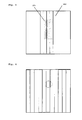
Die in den Beispielen verwendeten Filterbeutel sind zur Illustration der Anordnung der Diffusoren im Inneren in den nachfolgend abgebildeten Figuren dargestellt. Die Beutel werden dabei in Projektion mit Blick auf die Beuteloberseite von der Beutelunterseite aus betrachtet. Sofern nicht anders angegeben, sind alle Diffusoren aus Streifen eines dreilagigen Vliesmaterials gebildet. Bei den folgenden Figurenbezeichnungen bedeutet eine Anordnung der Diffusoren "längs" eine in den Figuren dargestellte vertikale Anordnung der Diffusoren, während "quer" eine horizontale Anordnung der Diffusoren innerhalb des Filterbeutels bedeutet. Eine diesbezügliche Unterscheidung ist notwendig, da die Einlassöffnung asymmetrisch bezüglich des Schwerpunktes des Filterbeutels angeordnet ist.The filter bags used in the examples are shown to illustrate the arrangement of the diffusers inside in the figures shown below. The bags are viewed in projection from the bottom of the bag, looking at the top of the bag. Unless otherwise stated, all diffusers are formed from strips of a three layer nonwoven material. In the following figure designations, an arrangement of the diffusers means "longitudinally" a vertical arrangement of the diffusers shown in the figures, while "transverse" means a horizontal arrangement of the diffusers within the filter bag. A distinction in this regard is necessary because the inlet opening is arranged asymmetrically with respect to the center of gravity of the filter bag.
Die Figuren zeigen im Einzelnen:
-
Figur 1 zeigt einen Filterbeutel ohne Diffusoren im Inneren (Vergleichsbeispiel 1*). -
Figur 2 zeigt einen Filterbeutel, der eine zusätzliche durchgehende Vlieslage (270 mm Breite) enthält (nicht erfindungsgemäß, Vergleichsbeispiel 2*). Die Lage D1 ist dabei an zwei Rändern durchgehend befestigt. -
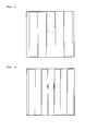
Figur 3 zeigt den eingangs erwähnten Filterbeutel mit zwei Strömungsrichtern SR1 (5 x 15 mm Folie) und SR2 (5 x 25 mm Vliesstoff), wobei beide Strömungsrichter längs im Filterbeutel angeordnet sind. -
Figur 4 zeigt einen erfindungsgemäßen Filterbeutel mit einem längs angeordneten Diffusor (11 x 22 mm) (Beispiel 4). -
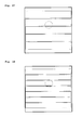
Figur 5 zeigt einen erfindungsgemäßen Filterbeutel mit einem quer angeordneten Diffusor (22 x 11 mm) (Beispiel 5). -
Figur 6 zeigt einen erfindungsgemäßen Filterbeutel mit einem aus Polypropylen-Filamenten gebildeten Diffusor (Beispiel 6). -
Figur 7 zeigt einen erfindungsgemäßen Filterbeutel mit einem längs angeordneten Diffusor (10 x 11 mm) (Beispiel 7). -
Figur 8 zeigt einen erfindungsgemäßen Filterbeutel mit einem quer angeordneten Diffusor (10 x 11 mm) (Beispiel 8). -
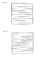
Figur 9 zeigt einen erfindungsgemäßen Filterbeutel mit einem längs angeordneten Diffusor (3 x 90 mm) (Beispiel 9). -
Figur 10 zeigt einen erfindungsgemäßen Filterbeutel mit einem längs angeordneten Diffusor (4 x 67,5 mm) (Beispiel 10). -
Figur 11 zeigt einen erfindungsgemäßen Filterbeutel mit einem längs angeordneten Diffusor (5 x 54 mm) (Beispiel 11). -
Figur 12 zeigt einen erfindungsgemäßen Filterbeutel mit einem längs angeordneten Diffusor (7 x 38 mm) (Beispiel 12). -
Figur 13 zeigt einen erfindungsgemäßen Filterbeutel mit einem längs angeordneten Diffusor (9 x 30 mm) (Beispiel 13). -
Figur 14 zeigt einen erfindungsgemäßen Filterbeutel mit einem längs angeordneten Diffusor (11 x 22 mm) (Beispiel 14). -
Figur 15 zeigt einen erfindungsgemäßen Filterbeutel mit einem längs angeordneten Diffusor (24 x 5 mm) (Beispiel 15). -
Figur 16 zeigt einen erfindungsgemäßen Filterbeutel mit einem quer angeordneten Diffusor (3 x 90 mm) (Beispiel 16). -
Figur 17 zeigt einen erfindungsgemäßen Filterbeutel mit einem quer angeordneten Diffusor (4 x 54 mm) (Beispiel 17). -
Figur 18 zeigt einen erfindungsgemäßen Filterbeutel mit einem quer angeordneten Diffusor (7 x 38 mm) (Beispiel 18). -
Figur 19 zeigt einen erfindungsgemäßen Filterbeutel mit einem quer angeordneten Diffusor (9 x 30 mm) (Beispiel 19). -
Figur 20 zeigt einen erfindungsgemäßen Filterbeutel mit einem quer angeordneten Diffusor (11 x 22 mm) (Beispiel 20). -
Figur 21 zeigt einen erfindungsgemäßen Filterbeutel mit einem quer angeordneten Diffusor (24 x 11 mm) (Beispiel 21).
-
FIG. 1 shows a filter bag without diffusers inside (Comparative Example 1 *). -
FIG. 2 shows a filter bag containing an additional continuous nonwoven layer (270 mm width) (not according to the invention, Comparative Example 2 *). The layer D1 is fastened continuously on two edges. -
FIG. 3 shows the filter bag mentioned above with two flow straighteners SR1 (5 x 15 mm film) and SR2 (5 x 25 mm nonwoven fabric), both flow straighteners are arranged longitudinally in the filter bag. -
FIG. 4 shows a filter bag according to the invention with a longitudinally arranged diffuser (11 x 22 mm) (Example 4). -
FIG. 5 shows a filter bag according to the invention with a transversely arranged diffuser (22 x 11 mm) (Example 5). -
FIG. 6 shows a filter bag according to the invention with a diffuser formed of polypropylene filaments (Example 6). -
FIG. 7 shows a filter bag according to the invention with a longitudinally arranged diffuser (10 x 11 mm) (Example 7). -
FIG. 8 shows a filter bag according to the invention with a transverse diffuser (10 x 11 mm) (Example 8). -
FIG. 9 shows a filter bag according to the invention with a longitudinally arranged diffuser (3 x 90 mm) (Example 9). -
FIG. 10 shows a filter bag according to the invention with a longitudinally arranged diffuser (4 x 67.5 mm) (Example 10). -
FIG. 11 shows a filter bag according to the invention with a longitudinally arranged diffuser (5 x 54 mm) (Example 11). -
FIG. 12 shows a filter bag according to the invention with a longitudinally arranged diffuser (7 x 38 mm) (Example 12). -
FIG. 13 shows a filter bag according to the invention with a longitudinally arranged diffuser (9 x 30 mm) (Example 13). -
FIG. 14 shows a filter bag according to the invention with a longitudinally arranged diffuser (11 x 22 mm) (Example 14). -
FIG. 15 shows a filter bag according to the invention with a longitudinally arranged diffuser (24 x 5 mm) (Example 15). -
FIG. 16 shows a filter bag according to the invention with a transverse diffuser (3 x 90 mm) (Example 16). -
FIG. 17 shows a filter bag according to the invention with a transverse diffuser (4 x 54 mm) (Example 17). -
FIG. 18 shows a filter bag according to the invention with a transverse diffuser (7 x 38 mm) (Example 18). -
FIG. 19 shows a filter bag according to the invention with a transverse diffuser (9 x 30 mm) (Example 19). -
FIG. 20 shows a filter bag according to the invention with a transversely disposed diffuser (11 x 22 mm) (Example 20). -
FIG. 21 shows a filter bag according to the invention with a transverse diffuser (24 x 11 mm) (Example 21).
Die in den
In 

Claims (26)
dadurch gekennzeichnet, dass im Inneren des Flachbeutels zwischen der Beuteloberseite und der Beutelunterseite mindestens ein eine Zwischenebene bildender Diffusor angeordnet ist, der aus mindestens zwei zueinander angeordneten einzelnen Materialstreifen und/oder aus flächigen Materialgebilden, die länglich geformte Strömungsöffnungen aufweisen, besteht und dass der mindestens eine Diffusor an mindestens einer Seite mit der Beutelwand verbunden ist.Flat bag with a bag top and a bag bottom, the bag walls are formed from an air-permeable filter material and wherein in the bag top an inlet opening for the air to be filtered is introduced,
characterized in that in the interior of the flat bag between the bag top and the bag bottom at least one intermediate level forming diffuser is arranged, which consists of at least two mutually arranged individual strips of material and / or sheetlike material structures having elongated flow openings, and that the at least one Diffuser is connected at least one side to the bag wall.
dadurch gekennzeichnet, dass ein Diffusor in Form von Flächengebilden mit länglich geformten Strömungsöffnungen, der im Bereich der Einlassöffnung diese überdeckend angeordnet und an der Beuteloberseite befestigt ist, mit einer Fläche von < 10 %, bezogen auf die gesamte Beuteloberfläche, wobei die Breite der Materialstreifen durch den Durchmesser der Einströmungsöffnung ± 50 % definiert ist, ausgeschlossen ist.Flat bag according to claim 1,
characterized in that a diffuser in the form of sheets with oblong shaped flow openings, which in the region of the inlet opening these arranged overlapping and attached to the bag top, with an area of <10%, based on the entire bag surface, wherein the width of the strip of material the diameter of the inflow opening is defined ± 50% is excluded.
Priority Applications (19)
| Application Number | Priority Date | Filing Date | Title |
|---|---|---|---|
| DK09008064.9T DK2263507T3 (en) | 2009-06-19 | 2009-06-19 | Flat bag for a vacuum cleaner |
| DK18196359.6T DK3443880T3 (en) | 2009-06-19 | 2009-06-19 | Flat bag for vacuum cleaner |
| PL18196359T PL3443880T3 (en) | 2009-06-19 | 2009-06-19 | Flat bag for a vacuum cleaner |
| ES18196359T ES2876248T3 (en) | 2009-06-19 | 2009-06-19 | Flat bag for vacuum cleaner |
| EP18196359.6A EP3443880B1 (en) | 2009-06-19 | 2009-06-19 | Flat bag for a vacuum cleaner |
| DK17160494.5T DK3195782T3 (en) | 2009-06-19 | 2009-06-19 | Flat bag for vacuum cleaner |
| EP17160494.5A EP3195782B1 (en) | 2009-06-19 | 2009-06-19 | Sachet for a vacuum cleaner |
| ES09008064.9T ES2694479T3 (en) | 2009-06-19 | 2009-06-19 | Flat bag for a dust vacuum |
| PL17160494T PL3195782T3 (en) | 2009-06-19 | 2009-06-19 | Sachet for a vacuum cleaner |
| EP09008064.9A EP2263507B1 (en) | 2009-06-19 | 2009-06-19 | Flat bag for a vacuum cleaner |
| PL09008064T PL2263507T3 (en) | 2009-06-19 | 2009-06-19 | Flat bag for a vacuum cleaner |
| ES17160494T ES2716753T3 (en) | 2009-06-19 | 2009-06-19 | Flat bag for vacuum cleaner |
| DE202010018626.9U DE202010018626U1 (en) | 2009-06-19 | 2010-05-17 | Flat bag for vacuum cleaner |
| EP10721327.4A EP2442702B2 (en) | 2009-06-19 | 2010-05-17 | Flat bag for a vacuum cleaner |
| PCT/EP2010/003018 WO2010145740A1 (en) | 2009-06-19 | 2010-05-17 | Flat bag for vacuum cleaners |
| ES10721327T ES2595602T5 (en) | 2009-06-19 | 2010-05-17 | Flat bag for a vacuum cleaner |
| CN201080027292.8A CN102802484B (en) | 2009-06-19 | 2010-05-17 | Flat bag for vacuum cleaners |
| US13/377,668 US8702828B2 (en) | 2009-06-19 | 2010-05-17 | Flat bag for vacuum cleaners |
| AU2010262163A AU2010262163B2 (en) | 2009-06-19 | 2010-05-17 | Flat bag for vacuum cleaners |
Applications Claiming Priority (1)
| Application Number | Priority Date | Filing Date | Title |
|---|---|---|---|
| EP09008064.9A EP2263507B1 (en) | 2009-06-19 | 2009-06-19 | Flat bag for a vacuum cleaner |
Related Child Applications (4)
| Application Number | Title | Priority Date | Filing Date |
|---|---|---|---|
| EP18196359.6A Division EP3443880B1 (en) | 2009-06-19 | 2009-06-19 | Flat bag for a vacuum cleaner |
| EP17160494.5A Division-Into EP3195782B1 (en) | 2009-06-19 | 2009-06-19 | Sachet for a vacuum cleaner |
| EP17160494.5A Division EP3195782B1 (en) | 2009-06-19 | 2009-06-19 | Sachet for a vacuum cleaner |
| EP17160494.5A Previously-Filed-Application EP3195782B1 (en) | 2009-06-19 | 2009-06-19 | Sachet for a vacuum cleaner |
Publications (2)
| Publication Number | Publication Date |
|---|---|
| EP2263507A1 true EP2263507A1 (en) | 2010-12-22 |
| EP2263507B1 EP2263507B1 (en) | 2018-09-19 |
Family
ID=41259437
Family Applications (4)
| Application Number | Title | Priority Date | Filing Date |
|---|---|---|---|
| EP09008064.9A Active EP2263507B1 (en) | 2009-06-19 | 2009-06-19 | Flat bag for a vacuum cleaner |
| EP18196359.6A Active EP3443880B1 (en) | 2009-06-19 | 2009-06-19 | Flat bag for a vacuum cleaner |
| EP17160494.5A Active EP3195782B1 (en) | 2009-06-19 | 2009-06-19 | Sachet for a vacuum cleaner |
| EP10721327.4A Active EP2442702B2 (en) | 2009-06-19 | 2010-05-17 | Flat bag for a vacuum cleaner |
Family Applications After (3)
| Application Number | Title | Priority Date | Filing Date |
|---|---|---|---|
| EP18196359.6A Active EP3443880B1 (en) | 2009-06-19 | 2009-06-19 | Flat bag for a vacuum cleaner |
| EP17160494.5A Active EP3195782B1 (en) | 2009-06-19 | 2009-06-19 | Sachet for a vacuum cleaner |
| EP10721327.4A Active EP2442702B2 (en) | 2009-06-19 | 2010-05-17 | Flat bag for a vacuum cleaner |
Country Status (9)
| Country | Link |
|---|---|
| US (1) | US8702828B2 (en) |
| EP (4) | EP2263507B1 (en) |
| CN (1) | CN102802484B (en) |
| AU (1) | AU2010262163B2 (en) |
| DE (1) | DE202010018626U1 (en) |
| DK (3) | DK2263507T3 (en) |
| ES (4) | ES2716753T3 (en) |
| PL (3) | PL3443880T3 (en) |
| WO (1) | WO2010145740A1 (en) |
Cited By (10)
| Publication number | Priority date | Publication date | Assignee | Title |
|---|---|---|---|---|
| DE202011108953U1 (en) | 2011-12-02 | 2012-01-19 | Branofilter Gmbh | Dust filter bag with a dust collector insert |
| EP2502536A1 (en) | 2011-03-22 | 2012-09-26 | Jan Schultink | Ecologically efficient device for vacuum cleaning |
| DE102011120688A1 (en) | 2011-12-02 | 2013-04-11 | Branofilter Gmbh | Dust collector bag e.g. flat bag, for use in vacuum cleaner, has air-permeable dust trap inserts loosely arranged in bag inner space such that inserts are not permanently connected with bag walls or component of bag at any location |
| EP2644077A1 (en) | 2012-03-27 | 2013-10-02 | Jan Schultink | Method for optimising a device for vacuum cleaning with hand-held, compact or upright vacuum cleaning device and filter bag |
| EP2644075A1 (en) | 2012-03-27 | 2013-10-02 | Jan Schultink | Method for optimising a device for vacuum cleaning with hand-held, compact or upright vacuum cleaning device and filter bag |
| EP2759241A3 (en) * | 2013-01-28 | 2018-03-07 | Miele & Cie. KG | Filterbeutel für Staubsauger |
| US10080474B2 (en) | 2013-03-15 | 2018-09-25 | Eurofilters Holding N.V. | Vacuum cleaner filter bag |
| US11504662B2 (en) | 2016-03-17 | 2022-11-22 | Eurofilters N.V. | Vacuum cleaner filter bag made from recycled plastic |
| US11602252B2 (en) | 2016-03-17 | 2023-03-14 | Eurofilters N.V. | Vacuum cleaner filter bag made from recycled plastic |
| US11678782B2 (en) | 2016-10-06 | 2023-06-20 | Eurofilters N.V. | Vacuum cleaner filter bags comprising recycled textile materials and/or cotton linters |
Families Citing this family (3)
| Publication number | Priority date | Publication date | Assignee | Title |
|---|---|---|---|---|
| PL2662010T3 (en) * | 2010-03-19 | 2014-12-31 | Eurofilters Holding Nv | Vacuum cleaner filter bag |
| CN104116462B (en) * | 2013-04-26 | 2017-06-30 | 天佑电器(苏州)有限公司 | Filter bag and the dust catcher with the filter bag |
| ES2702036T3 (en) | 2013-08-09 | 2019-02-27 | Eurofilters Nv | Vacuum filter bag with spacer element |
Citations (13)
| Publication number | Priority date | Publication date | Assignee | Title |
|---|---|---|---|---|
| US2732911A (en) * | 1956-01-31 | Disposable dust bags for vacuum cleaners | ||
| EP0960645A2 (en) | 1998-05-11 | 1999-12-01 | Airflo Europe N.V. | Vacuum cleaner bag or filter, and method of filtering a gas |
| US6063171A (en) * | 1998-11-16 | 2000-05-16 | Electrolux Llc | Bactericidal vacuum cleaner filter bag |
| DE202006016304U1 (en) | 2006-10-23 | 2006-12-21 | Wolf Gmbh & Co. Kg | Filter bag e.g. flat bag, for vaccum cleaner, has strip and flexible section that are provided adjacent to inlet opening, where entered air flow is deflected by strip and flexible section, where strip is made of plastic foil |
| DE202006016303U1 (en) | 2006-10-23 | 2006-12-21 | Wolf Gmbh & Co. Kg | Filter bag for vacuum cleaner, has sac formed from air permeable filter material, and inlet opening formed at sac for air to be filtered, where inner cavity of sac is divided into two chambers |
| DE202006019108U1 (en) | 2006-12-19 | 2007-02-22 | Branofilter Gmbh | Method for manufacturing a vacuum cleaner dust bag with additional protection from damage has a front and back wall welded around the rectangular edges and barrier panels on the walls opposite the air inlet opening |
| EP1787560A1 (en) | 2005-11-22 | 2007-05-23 | Eurofilters Holding N.V | Vacuum cleaner dust bag with deflection device |
| EP1795247A1 (en) | 2005-12-12 | 2007-06-13 | Eurofilters N.V. | Vacuum cleaner dust bag |
| EP1804635A1 (en) | 2005-11-22 | 2007-07-11 | Eurofilters Holding N.V | Vacuum cleaner filter bag and use of said bag |
| DE202007010692U1 (en) | 2007-08-01 | 2007-10-04 | Branofilter Gmbh | Filter device in the form of a dust filter bag or a filter bag |
| DE102006051117B3 (en) | 2005-10-14 | 2008-01-31 | Papierverarbeitung Görlitz GmbH | Dust filter bag for vacuum cleaners |
| DE202008003248U1 (en) | 2008-03-07 | 2008-05-08 | Eurofilters Holding N.V. | Vacuum cleaner filter bag |
| DE202008007717U1 (en) | 2008-06-10 | 2008-08-07 | Wolf Pvg Gmbh & Co. Kg | filter bag |
Family Cites Families (9)
| Publication number | Priority date | Publication date | Assignee | Title |
|---|---|---|---|---|
| US3370405A (en) * | 1964-12-18 | 1968-02-27 | Studley Paper Company Inc | Vacuum cleaner filter bags and method of manufacturing same |
| US5647881A (en) * | 1995-04-20 | 1997-07-15 | Minnesota Mining And Manufacturing Company | Shock resistant high efficiency vacuum cleaner filter bag |
| JP4200980B2 (en) | 2005-04-13 | 2008-12-24 | 株式会社デンソー | In-vehicle collision detection device |
| DE502007004328D1 (en) * | 2006-04-25 | 2010-08-19 | Eurofilters Holding Nv | HOLDING PLATE FOR A VACUUM CLEANER BAG |
| ATE500773T1 (en) * | 2006-11-03 | 2011-03-15 | Eurofilters Holding Nv | ANTIBACTERIAL VACUUM CLEANER FILTER BAG |
| ES2325775T3 (en) * | 2007-08-17 | 2009-09-16 | Eurofilters Holding N.V. | VACUUM FILTER BAG. |
| EP2098151B1 (en) * | 2008-03-07 | 2013-10-23 | Eurofilters Holding N.V. | Vacuum cleaner filter bag |
| DE202008017637U1 (en) | 2008-09-04 | 2010-03-25 | Branofilter Gmbh | Dust filter bag device for a vacuum cleaner |
| DE102008061250C5 (en) † | 2008-12-10 | 2018-12-20 | Wolf Pvg Gmbh & Co. Kg | Vacuum cleaner bag and method of making a vacuum cleaner bag |
-
2009
- 2009-06-19 ES ES17160494T patent/ES2716753T3/en active Active
- 2009-06-19 DK DK09008064.9T patent/DK2263507T3/en active
- 2009-06-19 PL PL18196359T patent/PL3443880T3/en unknown
- 2009-06-19 ES ES18196359T patent/ES2876248T3/en active Active
- 2009-06-19 EP EP09008064.9A patent/EP2263507B1/en active Active
- 2009-06-19 DK DK18196359.6T patent/DK3443880T3/en active
- 2009-06-19 DK DK17160494.5T patent/DK3195782T3/en active
- 2009-06-19 EP EP18196359.6A patent/EP3443880B1/en active Active
- 2009-06-19 PL PL17160494T patent/PL3195782T3/en unknown
- 2009-06-19 PL PL09008064T patent/PL2263507T3/en unknown
- 2009-06-19 EP EP17160494.5A patent/EP3195782B1/en active Active
- 2009-06-19 ES ES09008064.9T patent/ES2694479T3/en active Active
-
2010
- 2010-05-17 EP EP10721327.4A patent/EP2442702B2/en active Active
- 2010-05-17 AU AU2010262163A patent/AU2010262163B2/en active Active
- 2010-05-17 ES ES10721327T patent/ES2595602T5/en active Active
- 2010-05-17 WO PCT/EP2010/003018 patent/WO2010145740A1/en active Application Filing
- 2010-05-17 CN CN201080027292.8A patent/CN102802484B/en active Active
- 2010-05-17 DE DE202010018626.9U patent/DE202010018626U1/en not_active Expired - Lifetime
- 2010-05-17 US US13/377,668 patent/US8702828B2/en active Active
Patent Citations (14)
| Publication number | Priority date | Publication date | Assignee | Title |
|---|---|---|---|---|
| US2732911A (en) * | 1956-01-31 | Disposable dust bags for vacuum cleaners | ||
| EP0960645A2 (en) | 1998-05-11 | 1999-12-01 | Airflo Europe N.V. | Vacuum cleaner bag or filter, and method of filtering a gas |
| US6063171A (en) * | 1998-11-16 | 2000-05-16 | Electrolux Llc | Bactericidal vacuum cleaner filter bag |
| DE102006051117B3 (en) | 2005-10-14 | 2008-01-31 | Papierverarbeitung Görlitz GmbH | Dust filter bag for vacuum cleaners |
| EP1804635A1 (en) | 2005-11-22 | 2007-07-11 | Eurofilters Holding N.V | Vacuum cleaner filter bag and use of said bag |
| EP1787560A1 (en) | 2005-11-22 | 2007-05-23 | Eurofilters Holding N.V | Vacuum cleaner dust bag with deflection device |
| EP1795247A1 (en) | 2005-12-12 | 2007-06-13 | Eurofilters N.V. | Vacuum cleaner dust bag |
| DE202006016304U1 (en) | 2006-10-23 | 2006-12-21 | Wolf Gmbh & Co. Kg | Filter bag e.g. flat bag, for vaccum cleaner, has strip and flexible section that are provided adjacent to inlet opening, where entered air flow is deflected by strip and flexible section, where strip is made of plastic foil |
| DE202006016303U1 (en) | 2006-10-23 | 2006-12-21 | Wolf Gmbh & Co. Kg | Filter bag for vacuum cleaner, has sac formed from air permeable filter material, and inlet opening formed at sac for air to be filtered, where inner cavity of sac is divided into two chambers |
| DE202006019108U1 (en) | 2006-12-19 | 2007-02-22 | Branofilter Gmbh | Method for manufacturing a vacuum cleaner dust bag with additional protection from damage has a front and back wall welded around the rectangular edges and barrier panels on the walls opposite the air inlet opening |
| DE202007010692U1 (en) | 2007-08-01 | 2007-10-04 | Branofilter Gmbh | Filter device in the form of a dust filter bag or a filter bag |
| DE202008003248U1 (en) | 2008-03-07 | 2008-05-08 | Eurofilters Holding N.V. | Vacuum cleaner filter bag |
| DE202008008989U1 (en) | 2008-03-07 | 2008-09-04 | Eurofilters Holding N.V. | Vacuum cleaner filter bag |
| DE202008007717U1 (en) | 2008-06-10 | 2008-08-07 | Wolf Pvg Gmbh & Co. Kg | filter bag |
Cited By (23)
| Publication number | Priority date | Publication date | Assignee | Title |
|---|---|---|---|---|
| US9713409B2 (en) | 2011-03-22 | 2017-07-25 | Eurofilters N.V. | Ecologically efficient vacuuming device |
| EP2502536A1 (en) | 2011-03-22 | 2012-09-26 | Jan Schultink | Ecologically efficient device for vacuum cleaning |
| EP2502537A1 (en) | 2011-03-22 | 2012-09-26 | Jan Schultink | Ecologically efficient device for vacuum cleaning |
| WO2012126616A1 (en) | 2011-03-22 | 2012-09-27 | Jan Schultink | Ecologically efficient vacuuming device |
| WO2012126617A1 (en) | 2011-03-22 | 2012-09-27 | Jan Schultink | Ecologically efficient vacuuming device |
| EP2502537B1 (en) | 2011-03-22 | 2019-01-02 | Eurofilters N.V. | Ecologically efficient device for vacuum cleaning |
| EP2502536B1 (en) | 2011-03-22 | 2019-01-02 | Eurofilters N.V. | Ecologically efficient device for vacuum cleaning |
| US9877627B2 (en) | 2011-03-22 | 2018-01-30 | Eurofilters N.V. | Ecologically efficient vacuuming device |
| DE102011120688A1 (en) | 2011-12-02 | 2013-04-11 | Branofilter Gmbh | Dust collector bag e.g. flat bag, for use in vacuum cleaner, has air-permeable dust trap inserts loosely arranged in bag inner space such that inserts are not permanently connected with bag walls or component of bag at any location |
| DE202011108953U1 (en) | 2011-12-02 | 2012-01-19 | Branofilter Gmbh | Dust filter bag with a dust collector insert |
| DE102011120688B4 (en) | 2011-12-02 | 2019-05-16 | Branofilter Gmbh | Dust filter bag with a dust collector insert |
| WO2013143789A1 (en) | 2012-03-27 | 2013-10-03 | Jan Schultink | Method for optimizing a vacuum‑cleaning apparatus having a cylinder vacuum cleaner or upright vacuum cleaner and a filter bag |
| EP2644075A1 (en) | 2012-03-27 | 2013-10-02 | Jan Schultink | Method for optimising a device for vacuum cleaning with hand-held, compact or upright vacuum cleaning device and filter bag |
| WO2013143790A2 (en) | 2012-03-27 | 2013-10-03 | Jan Schultink | Method for optimizing a device for vacuum cleaning with a hand-held, compact or upright vacuum cleaner and bag filter |
| US10045674B2 (en) | 2012-03-27 | 2018-08-14 | Eurofilters N.V. | Method for optimizing a vacuum cleaning apparatus having a cylinder vacuum cleaner or upright vacuum cleaner and a filter bag |
| US10052003B2 (en) | 2012-03-27 | 2018-08-21 | Eurofilters N.V. | Method for optimizing a device for vacuum cleaning with a hand-held, compact, or upright vacuum cleaner and bag filter |
| EP2644077A1 (en) | 2012-03-27 | 2013-10-02 | Jan Schultink | Method for optimising a device for vacuum cleaning with hand-held, compact or upright vacuum cleaning device and filter bag |
| EP2759241A3 (en) * | 2013-01-28 | 2018-03-07 | Miele & Cie. KG | Filterbeutel für Staubsauger |
| US10080474B2 (en) | 2013-03-15 | 2018-09-25 | Eurofilters Holding N.V. | Vacuum cleaner filter bag |
| US11504662B2 (en) | 2016-03-17 | 2022-11-22 | Eurofilters N.V. | Vacuum cleaner filter bag made from recycled plastic |
| US11602252B2 (en) | 2016-03-17 | 2023-03-14 | Eurofilters N.V. | Vacuum cleaner filter bag made from recycled plastic |
| US11896922B2 (en) | 2016-03-17 | 2024-02-13 | Eurofilters N.V. | Vacuum cleaner filter bag with powdery and/or fibrous recycled material |
| US11678782B2 (en) | 2016-10-06 | 2023-06-20 | Eurofilters N.V. | Vacuum cleaner filter bags comprising recycled textile materials and/or cotton linters |
Also Published As
| Publication number | Publication date |
|---|---|
| ES2694479T3 (en) | 2018-12-21 |
| EP2263507B1 (en) | 2018-09-19 |
| EP3443880A1 (en) | 2019-02-20 |
| PL2263507T3 (en) | 2019-02-28 |
| CN102802484A (en) | 2012-11-28 |
| US8702828B2 (en) | 2014-04-22 |
| AU2010262163A1 (en) | 2012-01-19 |
| AU2010262163B2 (en) | 2016-03-24 |
| EP2442702B1 (en) | 2016-08-31 |
| PL3443880T3 (en) | 2021-12-06 |
| DK3443880T3 (en) | 2021-07-26 |
| ES2595602T3 (en) | 2017-01-02 |
| EP2442702A1 (en) | 2012-04-25 |
| PL3195782T3 (en) | 2019-07-31 |
| ES2876248T3 (en) | 2021-11-12 |
| EP2442702B2 (en) | 2023-01-11 |
| EP3443880B1 (en) | 2021-05-12 |
| CN102802484B (en) | 2016-08-03 |
| ES2595602T5 (en) | 2023-03-30 |
| EP3195782A1 (en) | 2017-07-26 |
| DE202010018626U1 (en) | 2019-05-09 |
| EP3195782B1 (en) | 2019-01-09 |
| ES2716753T3 (en) | 2019-06-14 |
| DK3195782T3 (en) | 2019-04-15 |
| US20120272628A1 (en) | 2012-11-01 |
| DK2263507T3 (en) | 2019-01-14 |
| WO2010145740A1 (en) | 2010-12-23 |
Similar Documents
| Publication | Publication Date | Title |
|---|---|---|
| EP3195782B1 (en) | Sachet for a vacuum cleaner | |
| EP2263508B1 (en) | Flat bag for a vacuum cleaner with at least two diffusers | |
| EP2098151B1 (en) | Vacuum cleaner filter bag | |
| EP2215951B1 (en) | Filter bag | |
| EP1804635B2 (en) | Vacuum cleaner filter bag and use of said bag | |
| EP2366320B2 (en) | Vacuum cleaner filter bag | |
| DE202008003248U1 (en) | Vacuum cleaner filter bag | |
| EP2445382B1 (en) | Block bottom filter bag for vacuum cleaners | |
| DE202008016300U1 (en) | Dust bags | |
| WO2010000452A1 (en) | Dust filter bag having slotted material for insertion into a vacuum cleaner | |
| WO2014140127A1 (en) | Vacuum cleaner filter bag | |
| DE202009019156U1 (en) | Flat bag for vacuum cleaner | |
| DE102008031989A1 (en) | Dust filter bag for household vacuum cleaner, has impact device comprising impact surface, where wall section exhibiting impact surface has higher impact effect than wall section of bag wall that surrounds wall section exhibiting surface | |
| DE102011120688B4 (en) | Dust filter bag with a dust collector insert | |
| DE102009009152A1 (en) | Dust filter bag for household vacuum cleaner, has impact device comprising impact surface, where wall section exhibiting impact surface has higher impact effect than wall section of bag wall that surrounds wall section exhibiting surface | |
| WO2012126616A1 (en) | Ecologically efficient vacuuming device | |
| DE102009009154A1 (en) | Dust filter bag for household vacuum cleaner, has impact device comprising impact surface, where wall section exhibiting impact surface has higher impact effect than wall section of bag wall that surrounds wall section exhibiting surface |
Legal Events
| Date | Code | Title | Description |
|---|---|---|---|
| PUAI | Public reference made under article 153(3) epc to a published international application that has entered the european phase |
Free format text: ORIGINAL CODE: 0009012 |
|
| AK | Designated contracting states |
Kind code of ref document: A1 Designated state(s): AT BE BG CH CY CZ DE DK EE ES FI FR GB GR HR HU IE IS IT LI LT LU LV MC MK MT NL NO PL PT RO SE SI SK TR |
|
| AX | Request for extension of the european patent |
Extension state: AL BA RS |
|
| 17P | Request for examination filed |
Effective date: 20110124 |
|
| 17Q | First examination report despatched |
Effective date: 20140226 |
|
| STAA | Information on the status of an ep patent application or granted ep patent |
Free format text: STATUS: EXAMINATION IS IN PROGRESS |
|
| GRAP | Despatch of communication of intention to grant a patent |
Free format text: ORIGINAL CODE: EPIDOSNIGR1 |
|
| STAA | Information on the status of an ep patent application or granted ep patent |
Free format text: STATUS: GRANT OF PATENT IS INTENDED |
|
| RIN1 | Information on inventor provided before grant (corrected) |
Inventor name: SAUER, RALF Inventor name: SCHULTINK, JAN |
|
| INTG | Intention to grant announced |
Effective date: 20180418 |
|
| GRAS | Grant fee paid |
Free format text: ORIGINAL CODE: EPIDOSNIGR3 |
|
| GRAA | (expected) grant |
Free format text: ORIGINAL CODE: 0009210 |
|
| STAA | Information on the status of an ep patent application or granted ep patent |
Free format text: STATUS: THE PATENT HAS BEEN GRANTED |
|
| AK | Designated contracting states |
Kind code of ref document: B1 Designated state(s): AT BE BG CH CY CZ DE DK EE ES FI FR GB GR HR HU IE IS IT LI LT LU LV MC MK MT NL NO PL PT RO SE SI SK TR |
|
| REG | Reference to a national code |
Ref country code: GB Ref legal event code: FG4D Free format text: NOT ENGLISH |
|
| REG | Reference to a national code |
Ref country code: CH Ref legal event code: EP |
|
| REG | Reference to a national code |
Ref country code: AT Ref legal event code: REF Ref document number: 1042291 Country of ref document: AT Kind code of ref document: T Effective date: 20181015 |
|
| REG | Reference to a national code |
Ref country code: IE Ref legal event code: FG4D Free format text: LANGUAGE OF EP DOCUMENT: GERMAN |
|
| REG | Reference to a national code |
Ref country code: DE Ref legal event code: R096 Ref document number: 502009015289 Country of ref document: DE |
|
| REG | Reference to a national code |
Ref country code: NL Ref legal event code: FP |
|
| REG | Reference to a national code |
Ref country code: SE Ref legal event code: TRGR |
|
| REG | Reference to a national code |
Ref country code: ES Ref legal event code: FG2A Ref document number: 2694479 Country of ref document: ES Kind code of ref document: T3 Effective date: 20181221 |
|
| REG | Reference to a national code |
Ref country code: DK Ref legal event code: T3 Effective date: 20190106 |
|
| PG25 | Lapsed in a contracting state [announced via postgrant information from national office to epo] |
Ref country code: FI Free format text: LAPSE BECAUSE OF FAILURE TO SUBMIT A TRANSLATION OF THE DESCRIPTION OR TO PAY THE FEE WITHIN THE PRESCRIBED TIME-LIMIT Effective date: 20180919 Ref country code: NO Free format text: LAPSE BECAUSE OF FAILURE TO SUBMIT A TRANSLATION OF THE DESCRIPTION OR TO PAY THE FEE WITHIN THE PRESCRIBED TIME-LIMIT Effective date: 20181219 Ref country code: BG Free format text: LAPSE BECAUSE OF FAILURE TO SUBMIT A TRANSLATION OF THE DESCRIPTION OR TO PAY THE FEE WITHIN THE PRESCRIBED TIME-LIMIT Effective date: 20181219 Ref country code: LT Free format text: LAPSE BECAUSE OF FAILURE TO SUBMIT A TRANSLATION OF THE DESCRIPTION OR TO PAY THE FEE WITHIN THE PRESCRIBED TIME-LIMIT Effective date: 20180919 Ref country code: GR Free format text: LAPSE BECAUSE OF FAILURE TO SUBMIT A TRANSLATION OF THE DESCRIPTION OR TO PAY THE FEE WITHIN THE PRESCRIBED TIME-LIMIT Effective date: 20181220 |
|
| REG | Reference to a national code |
Ref country code: LT Ref legal event code: MG4D |
|
| PG25 | Lapsed in a contracting state [announced via postgrant information from national office to epo] |
Ref country code: HR Free format text: LAPSE BECAUSE OF FAILURE TO SUBMIT A TRANSLATION OF THE DESCRIPTION OR TO PAY THE FEE WITHIN THE PRESCRIBED TIME-LIMIT Effective date: 20180919 Ref country code: LV Free format text: LAPSE BECAUSE OF FAILURE TO SUBMIT A TRANSLATION OF THE DESCRIPTION OR TO PAY THE FEE WITHIN THE PRESCRIBED TIME-LIMIT Effective date: 20180919 |
|
| PG25 | Lapsed in a contracting state [announced via postgrant information from national office to epo] |
Ref country code: RO Free format text: LAPSE BECAUSE OF FAILURE TO SUBMIT A TRANSLATION OF THE DESCRIPTION OR TO PAY THE FEE WITHIN THE PRESCRIBED TIME-LIMIT Effective date: 20180919 Ref country code: IS Free format text: LAPSE BECAUSE OF FAILURE TO SUBMIT A TRANSLATION OF THE DESCRIPTION OR TO PAY THE FEE WITHIN THE PRESCRIBED TIME-LIMIT Effective date: 20190119 Ref country code: CZ Free format text: LAPSE BECAUSE OF FAILURE TO SUBMIT A TRANSLATION OF THE DESCRIPTION OR TO PAY THE FEE WITHIN THE PRESCRIBED TIME-LIMIT Effective date: 20180919 Ref country code: EE Free format text: LAPSE BECAUSE OF FAILURE TO SUBMIT A TRANSLATION OF THE DESCRIPTION OR TO PAY THE FEE WITHIN THE PRESCRIBED TIME-LIMIT Effective date: 20180919 |
|
| PG25 | Lapsed in a contracting state [announced via postgrant information from national office to epo] |
Ref country code: SK Free format text: LAPSE BECAUSE OF FAILURE TO SUBMIT A TRANSLATION OF THE DESCRIPTION OR TO PAY THE FEE WITHIN THE PRESCRIBED TIME-LIMIT Effective date: 20180919 Ref country code: PT Free format text: LAPSE BECAUSE OF FAILURE TO SUBMIT A TRANSLATION OF THE DESCRIPTION OR TO PAY THE FEE WITHIN THE PRESCRIBED TIME-LIMIT Effective date: 20190119 |
|
| REG | Reference to a national code |
Ref country code: DE Ref legal event code: R097 Ref document number: 502009015289 Country of ref document: DE |
|
| PLBE | No opposition filed within time limit |
Free format text: ORIGINAL CODE: 0009261 |
|
| STAA | Information on the status of an ep patent application or granted ep patent |
Free format text: STATUS: NO OPPOSITION FILED WITHIN TIME LIMIT |
|
| 26N | No opposition filed |
Effective date: 20190620 |
|
| PG25 | Lapsed in a contracting state [announced via postgrant information from national office to epo] |
Ref country code: SI Free format text: LAPSE BECAUSE OF FAILURE TO SUBMIT A TRANSLATION OF THE DESCRIPTION OR TO PAY THE FEE WITHIN THE PRESCRIBED TIME-LIMIT Effective date: 20180919 |
|
| PG25 | Lapsed in a contracting state [announced via postgrant information from national office to epo] |
Ref country code: MC Free format text: LAPSE BECAUSE OF FAILURE TO SUBMIT A TRANSLATION OF THE DESCRIPTION OR TO PAY THE FEE WITHIN THE PRESCRIBED TIME-LIMIT Effective date: 20180919 |
|
| REG | Reference to a national code |
Ref country code: CH Ref legal event code: PL |
|
| PG25 | Lapsed in a contracting state [announced via postgrant information from national office to epo] |
Ref country code: TR Free format text: LAPSE BECAUSE OF FAILURE TO SUBMIT A TRANSLATION OF THE DESCRIPTION OR TO PAY THE FEE WITHIN THE PRESCRIBED TIME-LIMIT Effective date: 20180919 |
|
| PG25 | Lapsed in a contracting state [announced via postgrant information from national office to epo] |
Ref country code: IE Free format text: LAPSE BECAUSE OF NON-PAYMENT OF DUE FEES Effective date: 20190619 |
|
| PG25 | Lapsed in a contracting state [announced via postgrant information from national office to epo] |
Ref country code: CH Free format text: LAPSE BECAUSE OF NON-PAYMENT OF DUE FEES Effective date: 20190630 Ref country code: LI Free format text: LAPSE BECAUSE OF NON-PAYMENT OF DUE FEES Effective date: 20190630 Ref country code: LU Free format text: LAPSE BECAUSE OF NON-PAYMENT OF DUE FEES Effective date: 20190619 |
|
| REG | Reference to a national code |
Ref country code: AT Ref legal event code: MM01 Ref document number: 1042291 Country of ref document: AT Kind code of ref document: T Effective date: 20190619 |
|
| PG25 | Lapsed in a contracting state [announced via postgrant information from national office to epo] |
Ref country code: AT Free format text: LAPSE BECAUSE OF NON-PAYMENT OF DUE FEES Effective date: 20190619 |
|
| PG25 | Lapsed in a contracting state [announced via postgrant information from national office to epo] |
Ref country code: CY Free format text: LAPSE BECAUSE OF FAILURE TO SUBMIT A TRANSLATION OF THE DESCRIPTION OR TO PAY THE FEE WITHIN THE PRESCRIBED TIME-LIMIT Effective date: 20180919 |
|
| PG25 | Lapsed in a contracting state [announced via postgrant information from national office to epo] |
Ref country code: HU Free format text: LAPSE BECAUSE OF FAILURE TO SUBMIT A TRANSLATION OF THE DESCRIPTION OR TO PAY THE FEE WITHIN THE PRESCRIBED TIME-LIMIT; INVALID AB INITIO Effective date: 20090619 Ref country code: MT Free format text: LAPSE BECAUSE OF FAILURE TO SUBMIT A TRANSLATION OF THE DESCRIPTION OR TO PAY THE FEE WITHIN THE PRESCRIBED TIME-LIMIT Effective date: 20180919 |
|
| PG25 | Lapsed in a contracting state [announced via postgrant information from national office to epo] |
Ref country code: MK Free format text: LAPSE BECAUSE OF FAILURE TO SUBMIT A TRANSLATION OF THE DESCRIPTION OR TO PAY THE FEE WITHIN THE PRESCRIBED TIME-LIMIT Effective date: 20180919 |
|
| PGFP | Annual fee paid to national office [announced via postgrant information from national office to epo] |
Ref country code: NL Payment date: 20230623 Year of fee payment: 15 Ref country code: FR Payment date: 20230620 Year of fee payment: 15 Ref country code: DK Payment date: 20230620 Year of fee payment: 15 Ref country code: DE Payment date: 20230629 Year of fee payment: 15 |
|
| PGFP | Annual fee paid to national office [announced via postgrant information from national office to epo] |
Ref country code: SE Payment date: 20230622 Year of fee payment: 15 Ref country code: PL Payment date: 20230612 Year of fee payment: 15 |
|
| PGFP | Annual fee paid to national office [announced via postgrant information from national office to epo] |
Ref country code: BE Payment date: 20230623 Year of fee payment: 15 |
|
| PGFP | Annual fee paid to national office [announced via postgrant information from national office to epo] |
Ref country code: IT Payment date: 20230629 Year of fee payment: 15 Ref country code: GB Payment date: 20230619 Year of fee payment: 15 Ref country code: ES Payment date: 20230703 Year of fee payment: 15 |