EP2262248A1 - Method for performing channel scan within a multi-channel broadcasting program receiver, and associated multi-channel broadcasting program receiver - Google Patents
Method for performing channel scan within a multi-channel broadcasting program receiver, and associated multi-channel broadcasting program receiver Download PDFInfo
- Publication number
- EP2262248A1 EP2262248A1 EP09007569A EP09007569A EP2262248A1 EP 2262248 A1 EP2262248 A1 EP 2262248A1 EP 09007569 A EP09007569 A EP 09007569A EP 09007569 A EP09007569 A EP 09007569A EP 2262248 A1 EP2262248 A1 EP 2262248A1
- Authority
- EP
- European Patent Office
- Prior art keywords
- frequency
- video
- signals
- channel
- broadcasting program
- Prior art date
- Legal status (The legal status is an assumption and is not a legal conclusion. Google has not performed a legal analysis and makes no representation as to the accuracy of the status listed.)
- Granted
Links
- 238000000034 method Methods 0.000 title claims abstract description 49
- 239000000969 carrier Substances 0.000 description 6
- 238000001228 spectrum Methods 0.000 description 6
- 230000002159 abnormal effect Effects 0.000 description 4
- 238000010586 diagram Methods 0.000 description 2
- 230000005236 sound signal Effects 0.000 description 2
- 230000003247 decreasing effect Effects 0.000 description 1
- 230000001419 dependent effect Effects 0.000 description 1
- 238000011161 development Methods 0.000 description 1
- 230000018109 developmental process Effects 0.000 description 1
- 230000006870 function Effects 0.000 description 1
Images




Classifications
-
- H—ELECTRICITY
- H04—ELECTRIC COMMUNICATION TECHNIQUE
- H04N—PICTORIAL COMMUNICATION, e.g. TELEVISION
- H04N5/00—Details of television systems
- H04N5/44—Receiver circuitry for the reception of television signals according to analogue transmission standards
- H04N5/50—Tuning indicators; Automatic tuning control
-
- H—ELECTRICITY
- H04—ELECTRIC COMMUNICATION TECHNIQUE
- H04N—PICTORIAL COMMUNICATION, e.g. TELEVISION
- H04N21/00—Selective content distribution, e.g. interactive television or video on demand [VOD]
- H04N21/40—Client devices specifically adapted for the reception of or interaction with content, e.g. set-top-box [STB]; Operations thereof
- H04N21/41—Structure of client; Structure of client peripherals
- H04N21/426—Internal components of the client ; Characteristics thereof
- H04N21/42607—Internal components of the client ; Characteristics thereof for processing the incoming bitstream
- H04N21/4263—Internal components of the client ; Characteristics thereof for processing the incoming bitstream involving specific tuning arrangements, e.g. two tuners
-
- H—ELECTRICITY
- H04—ELECTRIC COMMUNICATION TECHNIQUE
- H04N—PICTORIAL COMMUNICATION, e.g. TELEVISION
- H04N21/00—Selective content distribution, e.g. interactive television or video on demand [VOD]
- H04N21/40—Client devices specifically adapted for the reception of or interaction with content, e.g. set-top-box [STB]; Operations thereof
- H04N21/43—Processing of content or additional data, e.g. demultiplexing additional data from a digital video stream; Elementary client operations, e.g. monitoring of home network or synchronising decoder's clock; Client middleware
- H04N21/434—Disassembling of a multiplex stream, e.g. demultiplexing audio and video streams, extraction of additional data from a video stream; Remultiplexing of multiplex streams; Extraction or processing of SI; Disassembling of packetised elementary stream
- H04N21/4345—Extraction or processing of SI, e.g. extracting service information from an MPEG stream
-
- H—ELECTRICITY
- H04—ELECTRIC COMMUNICATION TECHNIQUE
- H04N—PICTORIAL COMMUNICATION, e.g. TELEVISION
- H04N5/00—Details of television systems
- H04N5/44—Receiver circuitry for the reception of television signals according to analogue transmission standards
- H04N5/46—Receiver circuitry for the reception of television signals according to analogue transmission standards for receiving on more than one standard at will
Definitions
- the present invention relates to a method for performing channel scan within a multi-channel broadcasting program receiver and an associated multi-channel broadcasting program receiver according to the pre-characterizing clauses of claims 1 and 9.
- a channel scan operation is required for detecting the channels available at a specific location in advance.
- a channel scan operation is typically performed by searching video carrier signals from a predetermined lower frequency band through to a predetermined upper frequency band of a plurality of frequencies intervened with the same predetermined frequency step, whose size can be referred to as the frequency step size.
- the frequency step size is very small.
- the frequency step size typically ranges from 50 KHz to 500 KHz.
- the frequencies to be searched typically ranges from 45.25 MHz through to 873.25 MHz.
- the conventional channel scan operation does not serve the user well, and there is a need to devise a novel method and an associated multi-channel broadcasting program receiver to speed up the channel scan operation.
- the present invention aims at providing a method for performing channel scan within a multi-channel broadcasting program receiver and an associated multi-channel broadcasting program receiver, thereby achieving one exemplary objective of speeding up the channel scan operation.
- the claimed method for performing channel scan within a multi-channel broadcasting program receiver includes following steps: calculating a plurality of frequency representatives of intermediate frequency (IF) signals of one or more received multi-channel broadcasting program signals within a specific band of a plurality of bands; and locating a video IF signal out of the IF signals according to the frequency representatives in order to determine a frequency of a video carrier corresponding to the specific band, wherein the frequency of the video carrier is utilized as a reference for tuning to an associated channel.
- IF intermediate frequency
- the claimed multi-channel broadcasting program receiver includes a tuner and a controller.
- the tuner is arranged to select one of a plurality of channels, while the controller is arranged to control the multi-channel broadcasting program receiver to perform channel scan according to code embedded in the controller or received from outside the controller.
- the controller is arranged to calculate a plurality of frequency representatives of IF signals of one or more received multi-channel broadcasting program signals within a specific band of a plurality of bands.
- the controller is arranged to locate a video IF signal out of the IF signals according to the frequency representatives in order to determine a frequency of a video carrier corresponding to the specific band, where the frequency of the video carrier is utilized as a reference for tuning to an associated channel.
- FIG. 1 illustrates a diagram of a multi-channel broadcasting program receiver 100 according to a first embodiment of the present invention.
- the multi-channel broadcasting program receiver 100 comprises a tuner 110, a processing module 120, a controller 130 and a memory 140.
- the tuner 110 is arranged to select one of a plurality of channels
- the processing module 120 is arranged to process received multi-channel broadcasting program signals, such as received television (TV) signals.
- the controller 130 is arranged to control operations of the multi-channel broadcasting program receiver 100 according to program code embedded in the controller 140 or received from outside the controller 140. More particularly, the controller 130 of this embodiment is arranged to control the multi-channel broadcasting program receiver 100 to perform channel scan according to the code.
- the controller 130 can be a micro processing unit (MPU) executing firmware code read from the memory 140, such as the code 140C stored in the memory 140.
- MPU micro processing unit
- the controller 130 can be a hardware controller with the code 140C embedded therein.
- the program code such as the code 140C can be stored in a memory such as the memory 140 or embedded in the control 130, depends on different variations of this embodiment.
- FIG. 2 is a flowchart of a method 910 for performing channel scan within a multi-channel broadcasting program receiver according to one embodiment of the present invention.
- the method 910 can be applied to the multi-channel broadcasting program receiver 100 shown in FIG. 1 , and can be implemented by utilizing the multi-channel broadcasting program receiver 100.
- the method 910 is described according to the first embodiment as follows.
- Step 912 the controller 130 executing the code 140C calculates a plurality of frequency representatives of intermediate frequency (IF) signals (e.g. some pilots such as IF versions of a video carrier and a sound carrier, and some suspicious pilots) of one or more received multi-channel broadcasting program signals within a specific band of a plurality of bands.
- the controller 130 is arranged to perform frequency transform on the IF signals to obtain frequency transform results as the frequency representatives.
- the frequency transform comprises Fast Fourier Transform (FFT), and the frequency transform results are FFT results.
- FFT Fast Fourier Transform
- the frequency transform comprises Discrete Cosine Transform (DCT), and the frequency transform results are DCT results.
- DCT Discrete Cosine Transform
- Step 914 the controller 130 executing the code 140C finds (or more specifically, locates) a video IF signal out of the IF signals (e.g. some pilots such as IF versions of a video carrier and a sound carrier, and some suspicious pilots), if exists, according to the frequency representatives in order to determine a frequency of a video carrier corresponding to the specific band, where the frequency of the video carrier is utilized as a reference for tuning to an associated channel.
- a video IF signal out of the IF signals e.g. some pilots such as IF versions of a video carrier and a sound carrier, and some suspicious pilots
- the controller 1 30 finds (or more specifically, locates) the video IF signal out of the IF signals of the n th iteration (if the video IF signal corresponding to the n th band B(n) exists) according to the frequency representatives obtained in Step 912 in the n th iteration.
- the frequency of the video carrier found in the n th iteration is utilized as the reference for tuning to the n th channel (e.g. the channel CH(n)).
- a storage within the multi-channel broadcasting program receiver 100 (e.g. the memory 140 or some other memory device, which is typically a non-volatile memory) is arranged to store the frequency of the video carrier corresponding to the specific band as the reference for tuning to the associated channel.
- the storage mentioned above stores the frequency of the video carrier corresponding to the n th band B(n) (i.e. the frequency of the video carrier found in the n th iteration) as the reference for tuning to the associated channel, such as the n th channel (e.g. the channel CH(n)).
- Step 917 the controller 130 executing the code 140C determines whether the channel scan is completed. If the controller 130 determines that the channel scan is completed, the loop shown in FIG. 2 will not continue (i.e. the break of the loop ends the flowchart); otherwise, Step 918 is entered. In particular, in a situation where the specific band represents the n th band B(n) mentioned above, the controller 130 determines whether the channel scan is completed by comparing n with N. More specifically, when n reaches N, the controller 130 determines that the channel scan is completed; otherwise (i.e. n ⁇ N in this situation), Step 918 is entered.
- Step 918 the controller 130 executing the code 140C changes at least one parameter to continue with the next band.
- the controller 130 simply performs an increase operation such as "n++", which causes n to be increased with an increment of one.
- the controller 130 calculates a plurality of frequency representatives of IF signals of one or more received multi-channel broadcasting program signals within each band of the plurality of bands such as the (N+1) bands B(0), B(1), ..., and B(N).
- the controller 130 eventually finds a video IF signal out of the IF signals of the one or more received multi-channel broadcasting program signals within each band, if the video IF signal corresponding to each band exists, according to the frequency representatives corresponding to each band, in order to determine a frequency of a video carrier corresponding to each band, where the frequency of the video carrier corresponding to each band is utilized as a reference for tuning to a corresponding channel of a plurality of channels such as the (N+1) channels CH(0), CH(1), ..., and CH(N).
- the storage mentioned above e.g. the memory 140 or the non-volatile memory
- FIG. 3 illustrates a plurality of statuses S1, S2, and S3 involved with the method 910 shown in FIG. 2 according to an embodiment of the present invention.
- the controller 130 controls the multi-channel broadcasting program receiver 100 to achieve a tuner phase lock loop (PLL) lock in the first status S1 (labeled "Tuner PLL Lock” in FIG. 3 ), achieve a video carrier lock in the second status S2 (labeled "Video Carrier Lock” in FIG. 3 ), and achieve a TV signal Lock in the third status S3 (labeled "TV signal Lock” in FIG. 3 ).
- PLL tuner phase lock loop
- the method 910 shown in FIG. 2 can reduce the overall channel scan time by rapidly achieving the video carrier lock in each iteration.
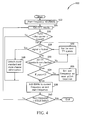
- FIG. 4 illustrates a control procedure 920 comprising implementation details of the method 910 shown in FIG. 2 according to an embodiment of the present invention, where this embodiment is a variation of the embodiment shown in FIG. 2 .
- the controller 130 of this embodiment operates according to a code 140C', which is a varied version of the code 140C.
- the control procedure 920 is described as follows.
- Step 922 the controller 130 initially sets the start frequency F start to be 45.25 MHz.
- the start frequency F start represents a start frequency of the channel scan for the band B(0).
- the controller 130 gets FFT results by performing FFT operations.
- the controller 130 stores the FFT results corresponding to the interval [F start + 0 MHz, F start + 6.5 MHz] on the frequency domain, and further determine whether there is any pilot whose power is greater than a predetermined threshold ViF_Th within the interval [F start + 0 MHz, F start + 6.5 MHz] on the frequency domain according to the FFT results.
- the controller 130 records the frequency of the pilot that is just found (i.e.
- Step 924 when Step 924 is re-entered in the subsequent iterations, the controller 130 can update the parameter P_num according to the latest value of the number of pilots that are found according to the FFT results corresponding to the interval [F start + 0 MHz, F start + 6.5 MHz] with the start frequency F start having the latest value thereof.
- Step 926 the controller 130 determines whether any valid video carrier is found.
- the controller 130 determines each pilot whose power is greater than the predetermined threshold VIF_Th to be the IF version of a candidate video carrier.
- the controller 130 determines that a valid video carrier is found. For example, the controller 130 can simply determine whether a valid video carrier is found according to the parameter P_num since the parameter P_num indicates the number of candidate video carriers during the determination of this step. If the controller 130 determines that a valid video carrier is found (i.e. P_num ⁇ 1), Step 928 is entered; otherwise (i.e. P_num ⁇ 1), Step 938 is entered, in order to perform the channel scan for the next band.
- Step 928 the controller 130 determines whether a TV signal is locked. If the controller 130 determines that a TV signal is locked (e.g. the multi-channel broadcasting program receiver 100 achieves the third status S3 mentioned above), Step 929 is entered; otherwise, Step 930 is entered.
- a TV signal e.g. the multi-channel broadcasting program receiver 100 achieves the third status S3 mentioned above.
- Step 929 the controller 130 detects the sound standard corresponding to the TV signal and stores the channel information of the TV signal. As a result, the TV signal becomes ready for use in the multi-channel broadcasting program receiver 100 since the required information of the channel that is transmitting the TV signal is obtained. Afterward, Step 938 is entered, in order to perform the channel scan for the next band.
- Step 930 the controller 130 determines whether all TV standards are checked. If the controller 130 determines that all TV standards are checked, Step 934 is entered; otherwise, Step 932 is entered, in order to try with another TV standard.
- Step 932 the controller 130 sets for the next TV system. More particularly, the controller 130 sets some control registers to make the multi-channel broadcasting program receiver 100 comply with the next TV standard. Afterward, Step 928 is re-entered, in order to re-try to make the multi-channel broadcasting program receiver 100 achieve the third status S3 mentioned above.
- Step 934 the controller 130 determines whether the parameter P_num is equal to one. If the controller 130 determines that the parameter P_num is equal to one (e.g. the only remaining candidate video carrier is not qualified as a valid video carrier), Step 938 is entered, in order to perform the channel scan for the next band; otherwise, Step 936 is entered, in order to try with another candidate video carrier.
- Step 938 is entered, in order to perform the channel scan for the next band; otherwise, Step 936 is entered, in order to try with another candidate video carrier.
- Step 936 the controller 130 sets the new frequency (i.e. the subsequent frequency to be tried with) as the next pilot location (i.e. the frequency of the next pilot), where the parameter P_num is decreased with a decrease operation such as "P_num--".
- Step 928 is re-entered, in order to re-try to make the multi-channel broadcasting program receiver 100 achieve the third status S3 mentioned above.
- Step 938 the controller 130 adds 8 MHz to the current frequency as the next start frequency.
- the start frequency F start is increased to be the beginning of the next band (if exists), such as the lower frequency bond of the next band in this embodiment.
- Step 940 the controller 130 determines whether the next frequency (i.e. the latest value of the start frequency F start during the determination of this step) is greater than 873.25 MHz. If the controller 130 determines that the next frequency is greater than 873.25 MHz, the controller 130 ends the control procedure 920; otherwise, Step 924 is re-entered, in order to try with the next band.
- the next frequency i.e. the latest value of the start frequency F start during the determination of this step
- the controller 130 can properly determine whether a candidate video carrier is a valid video carrier according to the information recorded in Step 924 (e.g. the pilot location(s) and the parameter P_num), in order to save the time for the multi-channel broadcasting program receiver 100 to achieve the second status S2 mentioned above.
- the information recorded in Step 924 e.g. the pilot location(s) and the parameter P_num
- FIG. 5 illustrates a direct jump on the frequency domain during the channel scan for the specific band mentioned in Step 912 according to a special case of the embodiment shown in FIG. 4 .
- the controller 130 can jump directly from the beginning of the band under consideration (e.g. the specific band) to the location where the video carrier is.
- the controller 130 can further jump 8 MHz from the location of the video carrier directly to the next band for further channel scan.
- the present invention method 910 and the associated multi-channel broadcasting program receiver 100 can greatly save the time for achieving the second status S2 in each iteration mentioned in the embodiment shown in FIG. 2 .
- the present invention method and the associated multi-channel broadcasting program receiver indeed reduce the overall time required for performing channel scan.
- the users will not suffer in long waiting time during the channel scan operation.
- the present invention method and the associated multi-channel broadcasting program receiver can rapidly jump out from a frequency band having no TV signal (e.g. in a situation where the only remaining candidate video carrier is not qualified as a valid video carrier), in order to save time and perform channel scan for the next band as mentioned in Step 934. As a result, the overall time of the channel scan operation can be greatly saved.
- the controller 130 can skip the audio signal check and directly jump to a frequency within the next band.
- the video IF signal e.g. the IF version of the video carrier
- the audio IF signal e.g.
- the controller 130 can skip the audio signal check and directly jump to a frequency within the next band (e.g. the beginning of the next band), in order to save time and perform the channel scan for the next band as soon as possible.
- FIG. 6 illustrates a spectrum of normal signals according to a special case of the embodiment shown in FIG. 4 , where the video carrier is stronger than the sound carrier.
- FIG. 7 illustrates a spectrum of abnormal signals having impulse noise according to another special case of the embodiment shown in FIG. 4 .
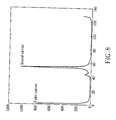
- FIG. 8 illustrates a spectrum of abnormal signals according to another special case of the embodiment shown in FIG. 4 , where the sound carrier is stronger than the video carrier.
- the pilots labeled as "Video carrier” or "Sound carrier” in FIG. 6 , FIG. 7 , and FIG. 8 are substantially the IF version of respective video/sound carriers. For simplicity, these pilots are labeled as "Video carrier” or "Sound carrier", respectively.
- the controller 130 determines the strongest IF signal of the IF signals (e.g. some pilots such as IF versions of a video carrier and a sound carrier, and some suspicious pilots) to be the video IF signal (e.g. the IF version of the video carrier).
- the pilot labeled "Video carrier” is indeed the IF version of a video carrier.
- the controller 130 of this embodiment can obtain the noise level mentioned above according to the frequency representatives corresponding to a predetermined noise estimation band.
- the controller 130 can average signal power levels within the noise estimate band as the noise level.
- the noise estimation band is positioned between the pilot labeled "Video carrier” and the pilot labeled "Sound carrier".
- the controller 130 can extract a portion of FFT results corresponding to the noise estimation band from all the FFT results, in order to determine whether any impulse noise exists according to the extracted portion of the FFT results.
- the controller 130 can determine the strongest IF signal of the IF signals to be the video IF signal.
- the controller 130 can utilize one or more additional criteria to make sure the determination of the locations of the video carrier and/or the sound carrier. For example, when the noise level reaches the predetermined threshold, such as the video IF threshold shown in FIG. 6 (e.g. the predetermined threshold VIF_Th mentioned above) or another threshold, the controller 130 can determine an IF signal of the IF signals that is most close to a predetermined side of an associated IF band to be the video IF signal. This is for illustrative purposes only, and is not meant to be a limitation of the present invention. According to a variation of this embodiment (e.g. a variation of the special case shown in FIG. 7 ), when the noise level reaches the predetermined threshold, the controller 130 can determine an IF signal of the IF signals that is larger than the predetermined threshold to be the video IF signal.
- the predetermined threshold such as the video IF threshold shown in FIG. 6 (e.g. the predetermined threshold VIF_Th mentioned above) or another threshold
- the controller 130 can determine an IF signal
- the associated IF band is substantially the whole IF band under consideration, while the predetermined side is the lower frequency part of the IF band as illustrated. That is, in this situation, the controller 130 determines the IF signal with the lowest frequency to be the video IF signal. After the location of the video carrier on the frequency domain is determined, the controller 130 can determine the location of the sound carrier on the frequency domain according to the TV standards.
- the sound carrier is stronger than the video carrier, causing the criterion based upon the predetermined threshold such as the video IF threshold shown in FIG. 6 (e.g. the predetermined threshold VIF_Th mentioned above) to be unsuitable for use.
- the controller 130 of this embodiment can determine according to one or more criteria to guarantee the correctness of the determination. For example, the controller 130 can still determine the IF signal with the lowest frequency in the whole IF band to be the video IF signal. In another example, the controller 130 can double check with the criterion based upon the predetermined threshold and the criterion based upon the predetermined side of the associated IF band.
- the controller 130 can compare the locations of the sound carrier with the locations of the video carrier, in order to determine whether the special case shown in FIG. 8 occurs since the order of the video carrier and the sound carrier on the frequency should comply with the TV standards.
Landscapes
- Engineering & Computer Science (AREA)
- Multimedia (AREA)
- Signal Processing (AREA)
- Circuits Of Receivers In General (AREA)
- Two-Way Televisions, Distribution Of Moving Picture Or The Like (AREA)
- Channel Selection Circuits, Automatic Tuning Circuits (AREA)
Abstract
Description
- The present invention relates to a method for performing channel scan within a multi-channel broadcasting program receiver and an associated multi-channel broadcasting program receiver according to the pre-characterizing clauses of
claims 1 and 9. - As users may operate portable multi-channel broadcasting program systems, such as television (TV) receivers implemented within portable devices or add-on modules, at different locations, and as the channels available at respective locations are not all the same, a channel scan operation is required for detecting the channels available at a specific location in advance. According to the related art, a channel scan operation is typically performed by searching video carrier signals from a predetermined lower frequency band through to a predetermined upper frequency band of a plurality of frequencies intervened with the same predetermined frequency step, whose size can be referred to as the frequency step size.
- Please note that, in contrast to the range of the frequencies to be searched, the frequency step size is very small. For example, the frequency step size typically ranges from 50 KHz to 500 KHz. However, the frequencies to be searched typically ranges from 45.25 MHz through to 873.25 MHz. As a result of applying the conventional channel scan method to the portable multi-channel broadcasting program systems, it usually takes too much time to find out the frequencies of all possible carriers, while only a portion of possible carriers are correct video carriers. Users may feel annoyed and may become impatient since they always need to wait for a long time to watch TV/listen to program when traveling to a new location.
- Therefore, the conventional channel scan operation does not serve the user well, and there is a need to devise a novel method and an associated multi-channel broadcasting program receiver to speed up the channel scan operation.
- This in mind, the present invention aims at providing a method for performing channel scan within a multi-channel broadcasting program receiver and an associated multi-channel broadcasting program receiver, thereby achieving one exemplary objective of speeding up the channel scan operation.
- This is achieved by a method and an associated multi-channel broadcasting program receiver according to
claims 1 and 9. The dependent claims pertain to corresponding further developments and improvements. - As will be seen more clearly from the detailed description following below, the claimed method for performing channel scan within a multi-channel broadcasting program receiver includes following steps: calculating a plurality of frequency representatives of intermediate frequency (IF) signals of one or more received multi-channel broadcasting program signals within a specific band of a plurality of bands; and locating a video IF signal out of the IF signals according to the frequency representatives in order to determine a frequency of a video carrier corresponding to the specific band, wherein the frequency of the video carrier is utilized as a reference for tuning to an associated channel.
- In addition, the claimed multi-channel broadcasting program receiver includes a tuner and a controller. The tuner is arranged to select one of a plurality of channels, while the controller is arranged to control the multi-channel broadcasting program receiver to perform channel scan according to code embedded in the controller or received from outside the controller. In addition, the controller is arranged to calculate a plurality of frequency representatives of IF signals of one or more received multi-channel broadcasting program signals within a specific band of a plurality of bands. Additionally, the controller is arranged to locate a video IF signal out of the IF signals according to the frequency representatives in order to determine a frequency of a video carrier corresponding to the specific band, where the frequency of the video carrier is utilized as a reference for tuning to an associated channel.
- In the following, the invention is further illustrated by way of example, taking reference to the accompanying drawings. Thereof
-
FIG. 1 is a diagram of a multi-channel broadcasting program receiver according to a first embodiment of the present invention, -
FIG. 2 is a flowchart of a method for performing channel scan within a multi-channel broadcasting program receiver according to one embodiment of the present invention, -
FIG. 3 illustrates a plurality of statuses involved with the method shown inFIG. 2 according to an embodiment of the present invention, -
FIG. 4 illustrates a control procedure comprising implementation details of the method shown inFIG. 2 according to an embodiment of the present invention, -
FIG. 5 illustrates a direct jump on the frequency domain during the channel scan for the specific band mentioned in the method shown inFIG. 2 according to a special case of the embodiment shown inFIG. 4 , -
FIG. 6 illustrates a spectrum of normal signals according to a special case of the embodiment shown inFIG. 4 , -
FIG. 7 illustrates a spectrum of abnormal signals having impulse noise according to another special case of the embodiment shown inFIG. 4 , and -
FIG. 8 illustrates a spectrum of abnormal signals according to another special case of the embodiment shown inFIG. 4 with the sound carrier being stronger than the video carrier. - Certain terms are used throughout the following description and claims, which refer to particular components. As one skilled in the art will appreciate, electronic equipment manufacturers may refer to a component by different names. This document does not intend to distinguish between components that differ in name but not in function. In the following description and in the claims, the terms "include" and "comprise" are used in an open-ended fashion, and thus should be interpreted to mean "include, but not limited to ...". Also, the term "couple" is intended to mean either an indirect or direct electrical connection. Accordingly, if one device is coupled to another device, that connection may be through a direct electrical connection, or through an indirect electrical connection via other devices and connections.
- Please refer to
FIG. 1 , which illustrates a diagram of a multi-channelbroadcasting program receiver 100 according to a first embodiment of the present invention. The multi-channelbroadcasting program receiver 100 comprises atuner 110, aprocessing module 120, acontroller 130 and amemory 140. Thetuner 110 is arranged to select one of a plurality of channels, and theprocessing module 120 is arranged to process received multi-channel broadcasting program signals, such as received television (TV) signals. In addition, thecontroller 130 is arranged to control operations of the multi-channelbroadcasting program receiver 100 according to program code embedded in thecontroller 140 or received from outside thecontroller 140. More particularly, thecontroller 130 of this embodiment is arranged to control the multi-channelbroadcasting program receiver 100 to perform channel scan according to the code. In this embodiment, thecontroller 130 can be a micro processing unit (MPU) executing firmware code read from thememory 140, such as thecode 140C stored in thememory 140. This is for illustrative purposes only, and is not meant to be a limitation of the present invention. According to a variation of this embodiment, thecontroller 130 can be a hardware controller with thecode 140C embedded therein. The program code such as thecode 140C can be stored in a memory such as thememory 140 or embedded in thecontrol 130, depends on different variations of this embodiment. -
FIG. 2 is a flowchart of amethod 910 for performing channel scan within a multi-channel broadcasting program receiver according to one embodiment of the present invention. Themethod 910 can be applied to the multi-channelbroadcasting program receiver 100 shown inFIG. 1 , and can be implemented by utilizing the multi-channelbroadcasting program receiver 100. Themethod 910 is described according to the first embodiment as follows. - In
Step 912, thecontroller 130 executing thecode 140C calculates a plurality of frequency representatives of intermediate frequency (IF) signals (e.g. some pilots such as IF versions of a video carrier and a sound carrier, and some suspicious pilots) of one or more received multi-channel broadcasting program signals within a specific band of a plurality of bands. For example, the plurality of bands comprises (N+1) bands B(0), B(1), ..., and B(N), and the specific band represents an nth band B(n), where the loop formed withSteps controller 130 is arranged to perform frequency transform on the IF signals to obtain frequency transform results as the frequency representatives. In particular, the frequency transform comprises Fast Fourier Transform (FFT), and the frequency transform results are FFT results. This is for illustrative purposes only, and is not meant to be a limitation of the present invention. According to a variation of this embodiment, the frequency transform comprises Discrete Cosine Transform (DCT), and the frequency transform results are DCT results. - In
Step 914, thecontroller 130 executing thecode 140C finds (or more specifically, locates) a video IF signal out of the IF signals (e.g. some pilots such as IF versions of a video carrier and a sound carrier, and some suspicious pilots), if exists, according to the frequency representatives in order to determine a frequency of a video carrier corresponding to the specific band, where the frequency of the video carrier is utilized as a reference for tuning to an associated channel. More particularly, in a situation where the specific band represents the nth band B(n) mentioned above, thecontroller 1 30 finds (or more specifically, locates) the video IF signal out of the IF signals of the nth iteration (if the video IF signal corresponding to the nth band B(n) exists) according to the frequency representatives obtained inStep 912 in the nth iteration. For example, the frequency of the video carrier found in the nth iteration is utilized as the reference for tuning to the nth channel (e.g. the channel CH(n)). - In
Step 916, under the control of thecontroller 130 executing thecode 140C, a storage within the multi-channel broadcasting program receiver 100 (e.g. thememory 140 or some other memory device, which is typically a non-volatile memory) is arranged to store the frequency of the video carrier corresponding to the specific band as the reference for tuning to the associated channel. For example, in a situation where the specific band represents the nth band B(n) mentioned above, the storage mentioned above stores the frequency of the video carrier corresponding to the nth band B(n) (i.e. the frequency of the video carrier found in the nth iteration) as the reference for tuning to the associated channel, such as the nth channel (e.g. the channel CH(n)). - In
Step 917, thecontroller 130 executing thecode 140C determines whether the channel scan is completed. If thecontroller 130 determines that the channel scan is completed, the loop shown inFIG. 2 will not continue (i.e. the break of the loop ends the flowchart); otherwise,Step 918 is entered. In particular, in a situation where the specific band represents the nth band B(n) mentioned above, thecontroller 130 determines whether the channel scan is completed by comparing n with N. More specifically, when n reaches N, thecontroller 130 determines that the channel scan is completed; otherwise (i.e. n < N in this situation),Step 918 is entered. - In
Step 918, thecontroller 130 executing thecode 140C changes at least one parameter to continue with the next band. In particular, thecontroller 130 simply performs an increase operation such as "n++", which causes n to be increased with an increment of one. - As a result of the (N + 1) iterations of the loop shown in
FIG. 2 , thecontroller 130 calculates a plurality of frequency representatives of IF signals of one or more received multi-channel broadcasting program signals within each band of the plurality of bands such as the (N+1) bands B(0), B(1), ..., and B(N). In addition, thecontroller 130 eventually finds a video IF signal out of the IF signals of the one or more received multi-channel broadcasting program signals within each band, if the video IF signal corresponding to each band exists, according to the frequency representatives corresponding to each band, in order to determine a frequency of a video carrier corresponding to each band, where the frequency of the video carrier corresponding to each band is utilized as a reference for tuning to a corresponding channel of a plurality of channels such as the (N+1) channels CH(0), CH(1), ..., and CH(N). Additionally, the storage mentioned above (e.g. thememory 140 or the non-volatile memory) is arranged to store the frequency of the video carrier corresponding to each band as the reference for tuning to the corresponding channel of the plurality of channels. -
FIG. 3 illustrates a plurality of statuses S1, S2, and S3 involved with themethod 910 shown inFIG. 2 according to an embodiment of the present invention. In each of the (N + 1) iterations, when it is applicable, thecontroller 130 controls the multi-channelbroadcasting program receiver 100 to achieve a tuner phase lock loop (PLL) lock in the first status S1 (labeled "Tuner PLL Lock" inFIG. 3 ), achieve a video carrier lock in the second status S2 (labeled "Video Carrier Lock" inFIG. 3 ), and achieve a TV signal Lock in the third status S3 (labeled "TV signal Lock" inFIG. 3 ). Themethod 910 shown inFIG. 2 can reduce the overall channel scan time by rapidly achieving the video carrier lock in each iteration. -
FIG. 4 illustrates acontrol procedure 920 comprising implementation details of themethod 910 shown inFIG. 2 according to an embodiment of the present invention, where this embodiment is a variation of the embodiment shown inFIG. 2 . Thecontroller 130 of this embodiment operates according to acode 140C', which is a varied version of thecode 140C. Thecontrol procedure 920 is described as follows. - In
Step 922, thecontroller 130 initially sets the start frequency Fstart to be 45.25 MHz. In this embodiment, the start frequency Fstart represents a start frequency of the channel scan for the band B(0). - In
Step 924, thecontroller 130 gets FFT results by performing FFT operations. In particular, thecontroller 130 stores the FFT results corresponding to the interval [Fstart + 0 MHz, Fstart + 6.5 MHz] on the frequency domain, and further determine whether there is any pilot whose power is greater than a predetermined threshold ViF_Th within the interval [Fstart + 0 MHz, Fstart + 6.5 MHz] on the frequency domain according to the FFT results. When it is determined that a pilot whose power is greater than the predetermined threshold VIF_Th is found, thecontroller 130 records the frequency of the pilot that is just found (i.e. the pilot location on the frequency axis), and further records a parameter P_num representing the number of pilots that are found according to the FFT results corresponding to the interval [Fstart + 0 MHz, Fstart + 6.5 MHz]. In particular, whenStep 924 is re-entered in the subsequent iterations, thecontroller 130 can update the parameter P_num according to the latest value of the number of pilots that are found according to the FFT results corresponding to the interval [Fstart + 0 MHz, Fstart + 6.5 MHz] with the start frequency Fstart having the latest value thereof. - In
Step 926, thecontroller 130 determines whether any valid video carrier is found. According to this embodiment, thecontroller 130 determines each pilot whose power is greater than the predetermined threshold VIF_Th to be the IF version of a candidate video carrier. In addition, as long as the number of candidate video carriers (i.e. the number of pilots whose power is greater than the predetermined threshold VIF_Th) is greater than or equal to one, thecontroller 130 determines that a valid video carrier is found. For example, thecontroller 130 can simply determine whether a valid video carrier is found according to the parameter P_num since the parameter P_num indicates the number of candidate video carriers during the determination of this step. If thecontroller 130 determines that a valid video carrier is found (i.e. P_num ≥ 1),Step 928 is entered; otherwise (i.e. P_num < 1),Step 938 is entered, in order to perform the channel scan for the next band. - In
Step 928, thecontroller 130 determines whether a TV signal is locked. If thecontroller 130 determines that a TV signal is locked (e.g. the multi-channelbroadcasting program receiver 100 achieves the third status S3 mentioned above),Step 929 is entered; otherwise,Step 930 is entered. - In
Step 929, thecontroller 130 detects the sound standard corresponding to the TV signal and stores the channel information of the TV signal. As a result, the TV signal becomes ready for use in the multi-channelbroadcasting program receiver 100 since the required information of the channel that is transmitting the TV signal is obtained. Afterward,Step 938 is entered, in order to perform the channel scan for the next band. - In
Step 930, thecontroller 130 determines whether all TV standards are checked. If thecontroller 130 determines that all TV standards are checked,Step 934 is entered; otherwise,Step 932 is entered, in order to try with another TV standard. - In
Step 932, thecontroller 130 sets for the next TV system. More particularly, thecontroller 130 sets some control registers to make the multi-channelbroadcasting program receiver 100 comply with the next TV standard. Afterward,Step 928 is re-entered, in order to re-try to make the multi-channelbroadcasting program receiver 100 achieve the third status S3 mentioned above. - In
Step 934, thecontroller 130 determines whether the parameter P_num is equal to one. If thecontroller 130 determines that the parameter P_num is equal to one (e.g. the only remaining candidate video carrier is not qualified as a valid video carrier),Step 938 is entered, in order to perform the channel scan for the next band; otherwise,Step 936 is entered, in order to try with another candidate video carrier. - In
Step 936, thecontroller 130 sets the new frequency (i.e. the subsequent frequency to be tried with) as the next pilot location (i.e. the frequency of the next pilot), where the parameter P_num is decreased with a decrease operation such as "P_num--". Afterward,Step 928 is re-entered, in order to re-try to make the multi-channelbroadcasting program receiver 100 achieve the third status S3 mentioned above. - In
Step 938, thecontroller 130 adds 8 MHz to the current frequency as the next start frequency. As a result, the start frequency Fstart is increased to be the beginning of the next band (if exists), such as the lower frequency bond of the next band in this embodiment. - In
Step 940, thecontroller 130 determines whether the next frequency (i.e. the latest value of the start frequency Fstart during the determination of this step) is greater than 873.25 MHz. If thecontroller 130 determines that the next frequency is greater than 873.25 MHz, thecontroller 130 ends thecontrol procedure 920; otherwise,Step 924 is re-entered, in order to try with the next band. - According to this embodiment, by operating based upon the
control procedure 920, thecontroller 130 can properly determine whether a candidate video carrier is a valid video carrier according to the information recorded in Step 924 (e.g. the pilot location(s) and the parameter P_num), in order to save the time for the multi-channelbroadcasting program receiver 100 to achieve the second status S2 mentioned above. Please refer toFIG. 5 , which illustrates a direct jump on the frequency domain during the channel scan for the specific band mentioned inStep 912 according to a special case of the embodiment shown inFIG. 4 . According to the FFT results obtained inStep 924, thecontroller 130 can jump directly from the beginning of the band under consideration (e.g. the specific band) to the location where the video carrier is. Afterward, thecontroller 130 can further jump 8 MHz from the location of the video carrier directly to the next band for further channel scan. As a result of utilizing the above disclosedcontrol procedure 920, thepresent invention method 910 and the associated multi-channelbroadcasting program receiver 100 can greatly save the time for achieving the second status S2 in each iteration mentioned in the embodiment shown inFIG. 2 . - Therefore, in contrast to the related art, the present invention method and the associated multi-channel broadcasting program receiver indeed reduce the overall time required for performing channel scan. When using a multi-channel broadcasting program receiver implemented according to the present invention, the users will not suffer in long waiting time during the channel scan operation.
- It is another advantage of the present invention that the present invention method and the associated multi-channel broadcasting program receiver can rapidly jump out from a frequency band having no TV signal (e.g. in a situation where the only remaining candidate video carrier is not qualified as a valid video carrier), in order to save time and perform channel scan for the next band as mentioned in
Step 934. As a result, the overall time of the channel scan operation can be greatly saved. - According to a variation of the embodiment shown in
FIG. 4 , when a plurality of suitable pilots obtained according to the FFT results have some relationships complying with the TV standards, thecontroller 130 can skip the audio signal check and directly jump to a frequency within the next band. For example, in a situation where the video IF signal (e.g. the IF version of the video carrier) is located at a firstrelative frequency 0 MHz of the interval [Fstart + 0 MHz, Fstart + 6.5 MHz] and the audio IF signal (e.g. the IF version of the sound carrier) is located at a second relative frequency 5.5 MHz of the interval [Fstart + 0 MHz, Fstart + 6.5 MHz] on the frequency domain, based upon the NTSC standards, thecontroller 130 can skip the audio signal check and directly jump to a frequency within the next band (e.g. the beginning of the next band), in order to save time and perform the channel scan for the next band as soon as possible. - Some implementation details are further described by referring to
FIG. 6 ,FIG. 7 , andFIG. 8 .FIG. 6 illustrates a spectrum of normal signals according to a special case of the embodiment shown inFIG. 4 , where the video carrier is stronger than the sound carrier.FIG. 7 illustrates a spectrum of abnormal signals having impulse noise according to another special case of the embodiment shown inFIG. 4 .FIG. 8 illustrates a spectrum of abnormal signals according to another special case of the embodiment shown inFIG. 4 , where the sound carrier is stronger than the video carrier. Please note that the pilots labeled as "Video carrier" or "Sound carrier" inFIG. 6 ,FIG. 7 , andFIG. 8 are substantially the IF version of respective video/sound carriers. For simplicity, these pilots are labeled as "Video carrier" or "Sound carrier", respectively. - In a normal situation, such as the situation shown in
FIG. 6 , when a noise level does not reach a predetermined threshold, such as the video IF threshold shown inFIG. 6 (e.g. the predetermined threshold VIF_Th mentioned above) or another threshold, thecontroller 130 determines the strongest IF signal of the IF signals (e.g. some pilots such as IF versions of a video carrier and a sound carrier, and some suspicious pilots) to be the video IF signal (e.g. the IF version of the video carrier). In the special case shown inFIG. 6 , the pilot labeled "Video carrier" is indeed the IF version of a video carrier. - The
controller 130 of this embodiment can obtain the noise level mentioned above according to the frequency representatives corresponding to a predetermined noise estimation band. In practice, thecontroller 130 can average signal power levels within the noise estimate band as the noise level. As shown inFIG. 6 , the noise estimation band is positioned between the pilot labeled "Video carrier" and the pilot labeled "Sound carrier". As all the FFT results corresponding to the specific band B(n) have been obtained inStep 912, thecontroller 130 can extract a portion of FFT results corresponding to the noise estimation band from all the FFT results, in order to determine whether any impulse noise exists according to the extracted portion of the FFT results. As a result, in the normal situation, thecontroller 130 can determine the strongest IF signal of the IF signals to be the video IF signal. - In a situation where the impulse noise exists, such as the situation shown in
FIG. 7 , however, thecontroller 130 can utilize one or more additional criteria to make sure the determination of the locations of the video carrier and/or the sound carrier. For example, when the noise level reaches the predetermined threshold, such as the video IF threshold shown inFIG. 6 (e.g. the predetermined threshold VIF_Th mentioned above) or another threshold, thecontroller 130 can determine an IF signal of the IF signals that is most close to a predetermined side of an associated IF band to be the video IF signal. This is for illustrative purposes only, and is not meant to be a limitation of the present invention. According to a variation of this embodiment (e.g. a variation of the special case shown inFIG. 7 ), when the noise level reaches the predetermined threshold, thecontroller 130 can determine an IF signal of the IF signals that is larger than the predetermined threshold to be the video IF signal. - According to the special case shown in
FIG. 7 , the associated IF band is substantially the whole IF band under consideration, while the predetermined side is the lower frequency part of the IF band as illustrated. That is, in this situation, thecontroller 130 determines the IF signal with the lowest frequency to be the video IF signal. After the location of the video carrier on the frequency domain is determined, thecontroller 130 can determine the location of the sound carrier on the frequency domain according to the TV standards. - In another situation such as that shown in
FIG. 8 , the sound carrier is stronger than the video carrier, causing the criterion based upon the predetermined threshold such as the video IF threshold shown inFIG. 6 (e.g. the predetermined threshold VIF_Th mentioned above) to be unsuitable for use. Thecontroller 130 of this embodiment can determine according to one or more criteria to guarantee the correctness of the determination. For example, thecontroller 130 can still determine the IF signal with the lowest frequency in the whole IF band to be the video IF signal. In another example, thecontroller 130 can double check with the criterion based upon the predetermined threshold and the criterion based upon the predetermined side of the associated IF band. This is for illustrative purposes only, and is not meant to be a limitation of the present invention. According to a variation of this embodiment, thecontroller 130 can compare the locations of the sound carrier with the locations of the video carrier, in order to determine whether the special case shown inFIG. 8 occurs since the order of the video carrier and the sound carrier on the frequency should comply with the TV standards. - For completeness, various aspects of the invention are described in the following numbered clauses:
- Clause 1: A method for performing channel scan within a multi-channel broadcasting program receiver, the method comprising:
- calculating a plurality of frequency representatives of intermediate frequency (IF) signals of one or more received multi-channel broadcasting program signals within a specific band of a plurality of bands; and
- locating a video IF signal out of the IF signals according to the frequency representatives in order to determine a frequency of a video carrier corresponding to the specific band, wherein the frequency of the video carrier is utilized as a reference for tuning to an associated channel.
- Clause 2: The method of
clause 1, further comprising:- storing the frequency of the video carrier corresponding to the specific band as the reference for tuning to the associated channel.
- Clause 3: The method of
clause 1, wherein the step of calculating the plurality of frequency representatives of the IF signals of the received multi-channel broadcasting program signals within the specific band further comprises:- calculating a plurality of frequency representatives of IF signals of one or more received multi-channel broadcasting program signals within each band of the plurality of bands.
- Clause 4: The method of clause 3, wherein the step of locating the video IF signal out of the IF signals according to the frequency representatives in order to determine the frequency of the video carrier corresponding to the video IF signal further comprises:
- locating a video IF signal out of the IF signals of the one or more received multi-channel broadcasting program signals within each band, if the video IF signal corresponding to the band exists, according to the frequency representatives corresponding to the band, in order to determine a frequency of a video carrier corresponding to each band, wherein the frequency of the video carrier corresponding to each band is utilized as a reference for tuning to a corresponding channel of a plurality of channels.
- Clause 5: The method of clause 4, further comprising:
- storing the frequency of the video carrier corresponding to each band as the reference for tuning to the corresponding channel of the plurality of channels.
- Clause 6: The method of
clause 1, wherein the step of calculating the plurality of frequency representatives of the IF signals of the received multi-channel broadcasting program signals within the specific band of the plurality of bands further comprises:- performing frequency transform on the IF signals to obtain frequency transform results as the frequency representatives.
- Clause 7: The method of clause 6, wherein the frequency transform comprises Fast Fourier Transform (FFT); and the frequency transform results are FFT results.
- Clause 8: The method of clause 6, wherein the frequency transform comprises Discrete Cosine Transform (DCT); and the frequency transform results are DCT results.
- Clause 9: The method of
clause 1, wherein the step of locating the video IF signal out of the IF signals according to the frequency representatives in order to determine the frequency of the video carrier corresponding to the video IF signal further comprises:- when a noise level does not reach a predetermined threshold, determining a strongest IF signal of the IF signals to be the video IF signal.
- Clause 10: The method of
clause 1, wherein the step of locating the video IF signal out of the IF signals according to the frequency representatives in order to determine the frequency of the video carrier corresponding to the video IF signal further comprises:- when a noise level reaches a predetermined threshold, determining an IF signal of the IF signals that is larger than a predetermined threshold to be the video IF signal.
- Clause 11: A multi-channel broadcasting program receiver, comprising:
- a tuner arranged to select one of a plurality of channels; and
- a controller arranged to control the multi-channel broadcasting program receiver to perform channel scan according to code embedded in the controller or received from outside the controller, wherein the controller is arranged to calculate a plurality of frequency representatives of intermediate frequency (IF) signals of one or more received multi-channel broadcasting program signals within a specific band of a plurality of bands; and
- wherein the controller is arranged to locate a video IF signal out of the IF signals according to the frequency representatives in order to determine a frequency of a video carrier corresponding to the specific band, and the frequency of the video carrier is utilized as a reference for tuning to an associated channel.
- Clause 12: The multi-channel broadcasting program receiver of clause 11, further comprising:
- a storage arranged to store the frequency of the video carrier corresponding to the specific band as the reference for tuning to the associated channel.
- Clause 13: The multi-channel broadcasting program receiver of clause 11, wherein the controller is arranged to calculate a plurality of frequency representatives of IF signals of one or more received multi-channel broadcasting program signals within each band of the plurality of bands.
- Clause 14: The multi-channel broadcasting program receiver of clause 13, wherein the controller is arranged to locate a video IF signal out of the IF signals of the received multi-channel broadcasting program signals within each band, if the video IF signal corresponding to the band exists, according to the frequency representatives corresponding to the band, in order to determine a frequency of a video carrier corresponding to each band; and the frequency of the video carrier corresponding to each band is utilized as a reference for tuning to a corresponding channel of a plurality of channels.
- Clause 15: The multi-channel broadcasting program receiver of clause 14, further comprising:
- a storage arranged to store the frequency of the video carrier corresponding to each band as the reference for tuning to the corresponding channel of the plurality of channels.
- Clause 16: The multi-channel broadcasting program receiver of clause 11, wherein the controller is arranged to perform frequency transform on the IF signals to obtain frequency transform results as the frequency representatives.
- Clause 17: The multi-channel broadcasting program receiver of clause 16, wherein the frequency transform comprises Fast Fourier Transform (FFT); and the frequency transform results are FFT results.
- Clause 18: The multi-channel broadcasting program receiver of clause 16, wherein the frequency transform comprises Discrete Cosine Transform (DCT); and the frequency transform results are DCT results.
- Clause 19: The multi-channel broadcasting program receiver of clause 11, wherein when a noise level does not reach a predetermined threshold, the controller determines a strongest IF signal of the IF signals to be the video IF signal.
- Clause 20: The multi-channel broadcasting program receiver of clause 11, wherein when a noise level reaches a predetermined threshold, the controller determines an IF signal of the IF signals that is larger than a predetermined threshold to be the video IF signal.
- All combinations and sub-combinations of the above-described features also belong to the invention.
Claims (15)
- A method for performing channel scan within a multi-channel broadcasting program receiver (100), characterized by:calculating a plurality of frequency representatives of intermediate frequency (IF) signals of one or more received multi-channel broadcasting program signals within a specific band of a plurality of bands; andlocating a video IF signal out of the IF signals according to the frequency representatives in order to determine a frequency of a video carrier corresponding to the specific band, wherein the frequency of the video carrier is utilized as a reference for tuning to an associated channel.
- The method of claim 1, characterized in that the method further comprises:storing the frequency of the video carrier corresponding to the specific band as the reference for tuning to the associated channel.
- The method of claim 1, characterized in that the step of calculating the plurality of frequency representatives of the IF signals of the received multi-channel broadcasting program signals within the specific band further comprises:calculating a plurality of frequency representatives of IF signals of one or more received multi-channel broadcasting program signals within each band of the plurality of bands.
- The method of claim 3, characterized in that the step of locating the video IF signal out of the IF signals according to the frequency representatives in order to determine the frequency of the video carrier corresponding to the video IF signal further comprises:locating a video IF signal out of the IF signals of the one or more received multi-channel broadcasting program signals within each band, if the video IF signal corresponding to the band exists, according to the frequency representatives corresponding to the band, in order to determine a frequency of a video carrier corresponding to each band, wherein the frequency of the video carrier corresponding to each band is utilized as a reference for tuning to a corresponding channel of a plurality of channels.
- The method of claim 4, characterized in that the method further comprises:storing the frequency of the video carrier corresponding to each band as the reference for tuning to the corresponding channel of the plurality of channels.
- The method of claim 1, characterized in that the step of calculating the plurality of frequency representatives of the IF signals of the received multi-channel broadcasting program signals within the specific band of the plurality of bands further comprises:performing frequency transform on the IF signals to obtain frequency transform results as the frequency representatives.
- The method of claim 1, characterized in that the step of locating the video IF signal out of the IF signals according to the frequency representatives in order to determine the frequency of the video carrier corresponding to the video IF signal further comprises:when a noise level does not reach a predetermined threshold, determining a strongest IF signal of the IF signals to be the video IF signal.
- The method of claim 1, characterized in that the step of locating the video IF signal out of the IF signals according to the frequency representatives in order to determine the frequency of the video carrier corresponding to the video IF signal further comprises:when a noise level reaches a predetermined threshold, determining an IF signal of the IF signals that is larger than a predetermined threshold to be the video IF signal.
- A multi-channel broadcasting program receiver (100), comprising:a tuner (110) arranged to select one of a plurality of channels;characterized by:a controller (130) arranged to control the multi-channel broadcasting program receiver (100) to perform channel scan according to code embedded in the controller (130) or received from outside the controller (130), wherein the controller (130) is arranged to calculate a plurality of frequency representatives of intermediate frequency (IF) signals of one or more received multi-channel of bands;wherein the controller (130) is arranged to locate a video IF signal out of the IF signals according to the frequency representatives in order to determine a frequency of a video carrier corresponding to the specific band, and the frequency of the video carrier is utilized as a reference for tuning to an associated channel.
- The multi-channel broadcasting program receiver (100) of claim 9, characterized in that the multi-channel broadcasting program receiver (100) further comprises:a storage (140) arranged to store the frequency of the video carrier corresponding to the specific band as the reference for tuning to the associated channel.
- The multi-channel broadcasting program receiver (100) of claim 9, characterized in that the controller (130) is arranged to calculate a plurality of frequency representatives of IF signals of one or more received multi-channel broadcasting program signals within each band of the plurality of bands.
- The multi-channel broadcasting program receiver (100) of claim 11, characterized in that the controller (130) is arranged to locate a video IF signal out of the IF signals of the received multi-channel broadcasting program signals within each band, if the video IF signal corresponding to the band exists, according to the frequency representatives carrier corresponding to each band; and the frequency of the video carrier corresponding to each band is utilized as a reference for tuning to a corresponding channel of a plurality of channels.
- The multi-channel broadcasting program receiver (100) of claim 12, characterized in that the multi-channel broadcasting program receiver (100) further comprises:a storage (140) arranged to store the frequency of the video carrier corresponding to each band as the reference for tuning to the corresponding channel of the plurality of channels.
- The multi-channel broadcasting program receiver (100) of claim 9, characterized in that the controller (130) is arranged to perform frequency transform on the IF signals to obtain frequency transform results as the frequency representatives.
- The multi-channel broadcasting program receiver (100) of claim 9, characterized in that when a noise level does not reach a predetermined threshold, the controller (130) determines a strongest IF signal of the IF signals to be the video IF signal; or when a noise level reaches a predetermined threshold, the controller (1 30) determines an IF signal of the IF signals that is larger than a predetermined threshold to be the video IF signal.
Applications Claiming Priority (1)
| Application Number | Priority Date | Filing Date | Title |
|---|---|---|---|
| US12/477,923 US9380251B2 (en) | 2009-06-04 | 2009-06-04 | Method for performing channel scan within a multi-channel broadcasting program receiver, and associated multi-channel broadcasting program receiver |
Publications (2)
| Publication Number | Publication Date |
|---|---|
| EP2262248A1 true EP2262248A1 (en) | 2010-12-15 |
| EP2262248B1 EP2262248B1 (en) | 2011-09-28 |
Family
ID=42312862
Family Applications (1)
| Application Number | Title | Priority Date | Filing Date |
|---|---|---|---|
| EP09007569A Not-in-force EP2262248B1 (en) | 2009-06-04 | 2009-06-08 | Method for performing channel scan within a multi-channel broadcasting program receiver, and associated multi-channel broadcasting program receiver |
Country Status (5)
| Country | Link |
|---|---|
| US (1) | US9380251B2 (en) |
| EP (1) | EP2262248B1 (en) |
| CN (1) | CN101909183B (en) |
| AT (1) | ATE526781T1 (en) |
| TW (1) | TWI393380B (en) |
Families Citing this family (5)
| Publication number | Priority date | Publication date | Assignee | Title |
|---|---|---|---|---|
| US8842750B2 (en) * | 2010-12-21 | 2014-09-23 | Intel Corporation | Channel estimation for DVB-T2 demodulation using an adaptive prediction technique |
| EP2587797A1 (en) * | 2011-10-24 | 2013-05-01 | Mediatek Inc. | Channel scan apparatus and channel scan method for co-scanning different television signals in selected radio frequency channel |
| TWI544768B (en) * | 2014-11-18 | 2016-08-01 | 聯詠科技股份有限公司 | Signal receiving system, band detection method for multi-carrier signal and demodulating apparatus thereof |
| CN105516798B (en) * | 2015-12-17 | 2019-03-01 | 深圳Tcl数字技术有限公司 | TV terminal search method and system |
| FR3057732B1 (en) * | 2016-10-18 | 2018-11-02 | Sagemcom Broadband Sas | AUTOMATIC PRODUCTION METHOD OF A SERVICE PLAN |
Citations (3)
| Publication number | Priority date | Publication date | Assignee | Title |
|---|---|---|---|---|
| US20020157106A1 (en) * | 2001-04-18 | 2002-10-24 | Robert Uskali | Cable channel search systems |
| US20060037059A1 (en) * | 2004-08-10 | 2006-02-16 | Ali Corporation | Method of blind channel searching and estimation using a fast fourier transform mechanism |
| US20070098089A1 (en) * | 2005-10-28 | 2007-05-03 | Junsong Li | Performing blind scanning in a receiver |
Family Cites Families (6)
| Publication number | Priority date | Publication date | Assignee | Title |
|---|---|---|---|---|
| WO2000021206A1 (en) * | 1998-10-05 | 2000-04-13 | Aor, Ltd. | Wideband receiver and channel scanning method |
| US7383567B2 (en) | 2001-07-27 | 2008-06-03 | Thomson Licensing | Method and system for creating a subset of programming channels |
| JP4967357B2 (en) | 2006-02-03 | 2012-07-04 | 船井電機株式会社 | Television receiver |
| TW200810547A (en) * | 2006-08-07 | 2008-02-16 | Tatung Co Ltd | Method and system to execute single TV channel scanning |
| CN101325669A (en) * | 2007-06-14 | 2008-12-17 | 扬智科技股份有限公司 | Method for blind scanning digital television broadcast receiving system by using frequency spectrum analysis |
| JP2009044582A (en) * | 2007-08-10 | 2009-02-26 | Funai Electric Co Ltd | Digital broadcast receiving apparatus |
-
2009
- 2009-06-04 US US12/477,923 patent/US9380251B2/en not_active Expired - Fee Related
- 2009-06-08 EP EP09007569A patent/EP2262248B1/en not_active Not-in-force
- 2009-06-08 AT AT09007569T patent/ATE526781T1/en not_active IP Right Cessation
- 2009-09-25 TW TW098132468A patent/TWI393380B/en not_active IP Right Cessation
- 2009-10-12 CN CN2009101802738A patent/CN101909183B/en not_active Expired - Fee Related
Patent Citations (3)
| Publication number | Priority date | Publication date | Assignee | Title |
|---|---|---|---|---|
| US20020157106A1 (en) * | 2001-04-18 | 2002-10-24 | Robert Uskali | Cable channel search systems |
| US20060037059A1 (en) * | 2004-08-10 | 2006-02-16 | Ali Corporation | Method of blind channel searching and estimation using a fast fourier transform mechanism |
| US20070098089A1 (en) * | 2005-10-28 | 2007-05-03 | Junsong Li | Performing blind scanning in a receiver |
Also Published As
| Publication number | Publication date |
|---|---|
| TW201044809A (en) | 2010-12-16 |
| CN101909183B (en) | 2012-11-21 |
| TWI393380B (en) | 2013-04-11 |
| EP2262248B1 (en) | 2011-09-28 |
| US20100309388A1 (en) | 2010-12-09 |
| ATE526781T1 (en) | 2011-10-15 |
| CN101909183A (en) | 2010-12-08 |
| US9380251B2 (en) | 2016-06-28 |
Similar Documents
| Publication | Publication Date | Title |
|---|---|---|
| EP2512045B1 (en) | Dynamic alternative frequency channel switching in wireless terminal | |
| EP2262248B1 (en) | Method for performing channel scan within a multi-channel broadcasting program receiver, and associated multi-channel broadcasting program receiver | |
| WO2008072037A1 (en) | Improved fm transmission system and method | |
| EP2489224B1 (en) | Frequency scanning technique for a cell search procedure | |
| JP4596740B2 (en) | Digital broadcast receiver | |
| US8045067B2 (en) | Method and apparatus of locating channels in a frequency band | |
| US20030163830A1 (en) | Method for automatically searching cable TV band | |
| EP1804388B1 (en) | Digital broadcast reception device | |
| US9065577B2 (en) | Digital radio receiver system and method | |
| CN102939746A (en) | digital broadcast receiver | |
| EP2151925B1 (en) | Digital broadcast receiver | |
| EP2587797A1 (en) | Channel scan apparatus and channel scan method for co-scanning different television signals in selected radio frequency channel | |
| KR100983502B1 (en) | Method and apparatus for detecting frequency offset in orthogonal frequency division multiple system | |
| EP1998447B2 (en) | Method for estimating the type of broadcast for minimizing the time for channel installation | |
| US8879673B2 (en) | Method for coarse frequency synchronization in OFDM receiver | |
| JP3842585B2 (en) | Digital broadcast receiver | |
| US20070229715A1 (en) | Method and system of manually setting channels | |
| US8064558B2 (en) | Receiving apparatus | |
| US20040036809A1 (en) | Automatic channel selecting device | |
| WO2010007581A1 (en) | Method and apparatus for detecting analogue and digital signals | |
| WO2008072346A1 (en) | Controller, information device, control method, and control program | |
| JP2009111809A (en) | Receiver and radio broadcast receiver | |
| KR20050122800A (en) | Automatic channel scanning method of digital receiver | |
| KR20130090137A (en) | Method for setting service link operation in dab system, and computer-readable record medium with dab service link operation setting program for the same |
Legal Events
| Date | Code | Title | Description |
|---|---|---|---|
| PUAI | Public reference made under article 153(3) epc to a published international application that has entered the european phase |
Free format text: ORIGINAL CODE: 0009012 |
|
| AK | Designated contracting states |
Kind code of ref document: A1 Designated state(s): AT BE BG CH CY CZ DE DK EE ES FI FR GB GR HR HU IE IS IT LI LT LU LV MC MK MT NL NO PL PT RO SE SI SK TR |
|
| AX | Request for extension of the european patent |
Extension state: AL BA RS |
|
| 17P | Request for examination filed |
Effective date: 20110110 |
|
| GRAC | Information related to communication of intention to grant a patent modified |
Free format text: ORIGINAL CODE: EPIDOSCIGR1 |
|
| GRAP | Despatch of communication of intention to grant a patent |
Free format text: ORIGINAL CODE: EPIDOSNIGR1 |
|
| RIC1 | Information provided on ipc code assigned before grant |
Ipc: H04N 5/50 20060101AFI20110412BHEP Ipc: H04N 5/46 20060101ALI20110412BHEP |
|
| RIN1 | Information on inventor provided before grant (corrected) |
Inventor name: LIN, RAY-KUO Inventor name: CHIEN, LU-CHUNG Inventor name: KANG, CHIH-WEI |
|
| GRAS | Grant fee paid |
Free format text: ORIGINAL CODE: EPIDOSNIGR3 |
|
| GRAA | (expected) grant |
Free format text: ORIGINAL CODE: 0009210 |
|
| AK | Designated contracting states |
Kind code of ref document: B1 Designated state(s): AT BE BG CH CY CZ DE DK EE ES FI FR GB GR HR HU IE IS IT LI LT LU LV MC MK MT NL NO PL PT RO SE SI SK TR |
|
| REG | Reference to a national code |
Ref country code: GB Ref legal event code: FG4D |
|
| REG | Reference to a national code |
Ref country code: CH Ref legal event code: EP |
|
| REG | Reference to a national code |
Ref country code: IE Ref legal event code: FG4D |
|
| REG | Reference to a national code |
Ref country code: DE Ref legal event code: R096 Ref document number: 602009002744 Country of ref document: DE Effective date: 20111215 |
|
| REG | Reference to a national code |
Ref country code: NL Ref legal event code: VDEP Effective date: 20110928 |
|
| PG25 | Lapsed in a contracting state [announced via postgrant information from national office to epo] |
Ref country code: FI Free format text: LAPSE BECAUSE OF FAILURE TO SUBMIT A TRANSLATION OF THE DESCRIPTION OR TO PAY THE FEE WITHIN THE PRESCRIBED TIME-LIMIT Effective date: 20110928 Ref country code: HR Free format text: LAPSE BECAUSE OF FAILURE TO SUBMIT A TRANSLATION OF THE DESCRIPTION OR TO PAY THE FEE WITHIN THE PRESCRIBED TIME-LIMIT Effective date: 20110928 Ref country code: NO Free format text: LAPSE BECAUSE OF FAILURE TO SUBMIT A TRANSLATION OF THE DESCRIPTION OR TO PAY THE FEE WITHIN THE PRESCRIBED TIME-LIMIT Effective date: 20111228 Ref country code: SE Free format text: LAPSE BECAUSE OF FAILURE TO SUBMIT A TRANSLATION OF THE DESCRIPTION OR TO PAY THE FEE WITHIN THE PRESCRIBED TIME-LIMIT Effective date: 20110928 Ref country code: LT Free format text: LAPSE BECAUSE OF FAILURE TO SUBMIT A TRANSLATION OF THE DESCRIPTION OR TO PAY THE FEE WITHIN THE PRESCRIBED TIME-LIMIT Effective date: 20110928 |
|
| LTIE | Lt: invalidation of european patent or patent extension |
Effective date: 20110928 |
|
| PG25 | Lapsed in a contracting state [announced via postgrant information from national office to epo] |
Ref country code: GR Free format text: LAPSE BECAUSE OF FAILURE TO SUBMIT A TRANSLATION OF THE DESCRIPTION OR TO PAY THE FEE WITHIN THE PRESCRIBED TIME-LIMIT Effective date: 20111229 Ref country code: CY Free format text: LAPSE BECAUSE OF FAILURE TO SUBMIT A TRANSLATION OF THE DESCRIPTION OR TO PAY THE FEE WITHIN THE PRESCRIBED TIME-LIMIT Effective date: 20110928 Ref country code: LV Free format text: LAPSE BECAUSE OF FAILURE TO SUBMIT A TRANSLATION OF THE DESCRIPTION OR TO PAY THE FEE WITHIN THE PRESCRIBED TIME-LIMIT Effective date: 20110928 Ref country code: AT Free format text: LAPSE BECAUSE OF FAILURE TO SUBMIT A TRANSLATION OF THE DESCRIPTION OR TO PAY THE FEE WITHIN THE PRESCRIBED TIME-LIMIT Effective date: 20110928 Ref country code: SI Free format text: LAPSE BECAUSE OF FAILURE TO SUBMIT A TRANSLATION OF THE DESCRIPTION OR TO PAY THE FEE WITHIN THE PRESCRIBED TIME-LIMIT Effective date: 20110928 |
|
| REG | Reference to a national code |
Ref country code: AT Ref legal event code: MK05 Ref document number: 526781 Country of ref document: AT Kind code of ref document: T Effective date: 20110928 |
|
| PG25 | Lapsed in a contracting state [announced via postgrant information from national office to epo] |
Ref country code: BE Free format text: LAPSE BECAUSE OF FAILURE TO SUBMIT A TRANSLATION OF THE DESCRIPTION OR TO PAY THE FEE WITHIN THE PRESCRIBED TIME-LIMIT Effective date: 20110928 |
|
| PG25 | Lapsed in a contracting state [announced via postgrant information from national office to epo] |
Ref country code: CZ Free format text: LAPSE BECAUSE OF FAILURE TO SUBMIT A TRANSLATION OF THE DESCRIPTION OR TO PAY THE FEE WITHIN THE PRESCRIBED TIME-LIMIT Effective date: 20110928 Ref country code: SK Free format text: LAPSE BECAUSE OF FAILURE TO SUBMIT A TRANSLATION OF THE DESCRIPTION OR TO PAY THE FEE WITHIN THE PRESCRIBED TIME-LIMIT Effective date: 20110928 Ref country code: IS Free format text: LAPSE BECAUSE OF FAILURE TO SUBMIT A TRANSLATION OF THE DESCRIPTION OR TO PAY THE FEE WITHIN THE PRESCRIBED TIME-LIMIT Effective date: 20120128 |
|
| PG25 | Lapsed in a contracting state [announced via postgrant information from national office to epo] |
Ref country code: EE Free format text: LAPSE BECAUSE OF FAILURE TO SUBMIT A TRANSLATION OF THE DESCRIPTION OR TO PAY THE FEE WITHIN THE PRESCRIBED TIME-LIMIT Effective date: 20110928 Ref country code: RO Free format text: LAPSE BECAUSE OF FAILURE TO SUBMIT A TRANSLATION OF THE DESCRIPTION OR TO PAY THE FEE WITHIN THE PRESCRIBED TIME-LIMIT Effective date: 20110928 Ref country code: PT Free format text: LAPSE BECAUSE OF FAILURE TO SUBMIT A TRANSLATION OF THE DESCRIPTION OR TO PAY THE FEE WITHIN THE PRESCRIBED TIME-LIMIT Effective date: 20120130 Ref country code: IT Free format text: LAPSE BECAUSE OF FAILURE TO SUBMIT A TRANSLATION OF THE DESCRIPTION OR TO PAY THE FEE WITHIN THE PRESCRIBED TIME-LIMIT Effective date: 20110928 Ref country code: NL Free format text: LAPSE BECAUSE OF FAILURE TO SUBMIT A TRANSLATION OF THE DESCRIPTION OR TO PAY THE FEE WITHIN THE PRESCRIBED TIME-LIMIT Effective date: 20110928 |
|
| PG25 | Lapsed in a contracting state [announced via postgrant information from national office to epo] |
Ref country code: DK Free format text: LAPSE BECAUSE OF FAILURE TO SUBMIT A TRANSLATION OF THE DESCRIPTION OR TO PAY THE FEE WITHIN THE PRESCRIBED TIME-LIMIT Effective date: 20110928 |
|
| PLBE | No opposition filed within time limit |
Free format text: ORIGINAL CODE: 0009261 |
|
| STAA | Information on the status of an ep patent application or granted ep patent |
Free format text: STATUS: NO OPPOSITION FILED WITHIN TIME LIMIT |
|
| PG25 | Lapsed in a contracting state [announced via postgrant information from national office to epo] |
Ref country code: PL Free format text: LAPSE BECAUSE OF FAILURE TO SUBMIT A TRANSLATION OF THE DESCRIPTION OR TO PAY THE FEE WITHIN THE PRESCRIBED TIME-LIMIT Effective date: 20110928 |
|
| 26N | No opposition filed |
Effective date: 20120629 |
|
| REG | Reference to a national code |
Ref country code: DE Ref legal event code: R097 Ref document number: 602009002744 Country of ref document: DE Effective date: 20120629 |
|
| PG25 | Lapsed in a contracting state [announced via postgrant information from national office to epo] |
Ref country code: MC Free format text: LAPSE BECAUSE OF NON-PAYMENT OF DUE FEES Effective date: 20120630 |
|
| PG25 | Lapsed in a contracting state [announced via postgrant information from national office to epo] |
Ref country code: MK Free format text: LAPSE BECAUSE OF FAILURE TO SUBMIT A TRANSLATION OF THE DESCRIPTION OR TO PAY THE FEE WITHIN THE PRESCRIBED TIME-LIMIT Effective date: 20110928 |
|
| REG | Reference to a national code |
Ref country code: IE Ref legal event code: MM4A |
|
| PG25 | Lapsed in a contracting state [announced via postgrant information from national office to epo] |
Ref country code: ES Free format text: LAPSE BECAUSE OF FAILURE TO SUBMIT A TRANSLATION OF THE DESCRIPTION OR TO PAY THE FEE WITHIN THE PRESCRIBED TIME-LIMIT Effective date: 20120108 Ref country code: IE Free format text: LAPSE BECAUSE OF NON-PAYMENT OF DUE FEES Effective date: 20120608 |
|
| PG25 | Lapsed in a contracting state [announced via postgrant information from national office to epo] |
Ref country code: BG Free format text: LAPSE BECAUSE OF FAILURE TO SUBMIT A TRANSLATION OF THE DESCRIPTION OR TO PAY THE FEE WITHIN THE PRESCRIBED TIME-LIMIT Effective date: 20111228 |
|
| PG25 | Lapsed in a contracting state [announced via postgrant information from national office to epo] |
Ref country code: MT Free format text: LAPSE BECAUSE OF FAILURE TO SUBMIT A TRANSLATION OF THE DESCRIPTION OR TO PAY THE FEE WITHIN THE PRESCRIBED TIME-LIMIT Effective date: 20110928 |
|
| REG | Reference to a national code |
Ref country code: CH Ref legal event code: PL |
|
| PG25 | Lapsed in a contracting state [announced via postgrant information from national office to epo] |
Ref country code: CH Free format text: LAPSE BECAUSE OF NON-PAYMENT OF DUE FEES Effective date: 20130630 Ref country code: LI Free format text: LAPSE BECAUSE OF NON-PAYMENT OF DUE FEES Effective date: 20130630 Ref country code: TR Free format text: LAPSE BECAUSE OF FAILURE TO SUBMIT A TRANSLATION OF THE DESCRIPTION OR TO PAY THE FEE WITHIN THE PRESCRIBED TIME-LIMIT Effective date: 20110928 |
|
| PG25 | Lapsed in a contracting state [announced via postgrant information from national office to epo] |
Ref country code: LU Free format text: LAPSE BECAUSE OF NON-PAYMENT OF DUE FEES Effective date: 20120608 |
|
| PG25 | Lapsed in a contracting state [announced via postgrant information from national office to epo] |
Ref country code: HU Free format text: LAPSE BECAUSE OF FAILURE TO SUBMIT A TRANSLATION OF THE DESCRIPTION OR TO PAY THE FEE WITHIN THE PRESCRIBED TIME-LIMIT Effective date: 20090608 |
|
| REG | Reference to a national code |
Ref country code: FR Ref legal event code: PLFP Year of fee payment: 8 |
|
| REG | Reference to a national code |
Ref country code: FR Ref legal event code: PLFP Year of fee payment: 9 |
|
| REG | Reference to a national code |
Ref country code: FR Ref legal event code: PLFP Year of fee payment: 10 |
|
| PGFP | Annual fee paid to national office [announced via postgrant information from national office to epo] |
Ref country code: FR Payment date: 20180626 Year of fee payment: 10 |
|
| PGFP | Annual fee paid to national office [announced via postgrant information from national office to epo] |
Ref country code: GB Payment date: 20180627 Year of fee payment: 10 Ref country code: DE Payment date: 20180627 Year of fee payment: 10 |
|
| REG | Reference to a national code |
Ref country code: DE Ref legal event code: R119 Ref document number: 602009002744 Country of ref document: DE |
|
| GBPC | Gb: european patent ceased through non-payment of renewal fee |
Effective date: 20190608 |
|
| PG25 | Lapsed in a contracting state [announced via postgrant information from national office to epo] |
Ref country code: GB Free format text: LAPSE BECAUSE OF NON-PAYMENT OF DUE FEES Effective date: 20190608 Ref country code: DE Free format text: LAPSE BECAUSE OF NON-PAYMENT OF DUE FEES Effective date: 20200101 |
|
| PG25 | Lapsed in a contracting state [announced via postgrant information from national office to epo] |
Ref country code: FR Free format text: LAPSE BECAUSE OF NON-PAYMENT OF DUE FEES Effective date: 20190630 |