EP2262207A1 - Power management in an internet protocol (IP) telephone - Google Patents
Power management in an internet protocol (IP) telephone Download PDFInfo
- Publication number
- EP2262207A1 EP2262207A1 EP10154622A EP10154622A EP2262207A1 EP 2262207 A1 EP2262207 A1 EP 2262207A1 EP 10154622 A EP10154622 A EP 10154622A EP 10154622 A EP10154622 A EP 10154622A EP 2262207 A1 EP2262207 A1 EP 2262207A1
- Authority
- EP
- European Patent Office
- Prior art keywords
- operating mode
- low
- power operating
- telephone
- telephone set
- Prior art date
- Legal status (The legal status is an assumption and is not a legal conclusion. Google has not performed a legal analysis and makes no representation as to the accuracy of the status listed.)
- Granted
Links
Images

Classifications
-
- H—ELECTRICITY
- H04—ELECTRIC COMMUNICATION TECHNIQUE
- H04M—TELEPHONIC COMMUNICATION
- H04M1/00—Substation equipment, e.g. for use by subscribers
- H04M1/253—Telephone sets using digital voice transmission
- H04M1/2535—Telephone sets using digital voice transmission adapted for voice communication over an Internet Protocol [IP] network
-
- Y—GENERAL TAGGING OF NEW TECHNOLOGICAL DEVELOPMENTS; GENERAL TAGGING OF CROSS-SECTIONAL TECHNOLOGIES SPANNING OVER SEVERAL SECTIONS OF THE IPC; TECHNICAL SUBJECTS COVERED BY FORMER USPC CROSS-REFERENCE ART COLLECTIONS [XRACs] AND DIGESTS
- Y02—TECHNOLOGIES OR APPLICATIONS FOR MITIGATION OR ADAPTATION AGAINST CLIMATE CHANGE
- Y02D—CLIMATE CHANGE MITIGATION TECHNOLOGIES IN INFORMATION AND COMMUNICATION TECHNOLOGIES [ICT], I.E. INFORMATION AND COMMUNICATION TECHNOLOGIES AIMING AT THE REDUCTION OF THEIR OWN ENERGY USE
- Y02D30/00—Reducing energy consumption in communication networks
- Y02D30/70—Reducing energy consumption in communication networks in wireless communication networks
Definitions
- the present invention relates generally to power management and Internet protocol (IP) telephones, and more particularly, to an IP phone having power management sleep modes.
- IP Internet protocol
- IP Internet protocol
- VOIP voice-over-Internet protocol
- IP desktop telephones typically include a direct connection such as an Ethernet port, eliminating the need for another device, such as a personal computer, to interface the IP telephone to the Internet for a single connection.
- Relatively low-cost controllers capable of routing to multiple IP telephones further increase the flexibility and cost-savings available by using IP telephones in the office and hotel environments. As the popularity of IP telephones increases, IP desktop telephones can also expect to proliferate in the home environment, as well.
- IP Internet protocol
- a low-power operating mode disables at least a portion of the IP telephone. The low-power operating mode is cancelled upon an indication that a user either is or should be present at the IP telephone.
- the present invention encompasses network protocol telephones and methods, including IP telephones, along with telephone systems including network protocol telephones.
- the network protocol telephones include power management capability in which a low-power operating mode is initiated either by a scheduled timer, a command send from a central telephone controller, an indication of proximity of a user received from some other device, activation of a special key or special key combination/sequence that places the network protocol telephone in a low-power operating mode, or the like.
- the telephone exits the low-power operating mode in response to user activity, an indication of user proximity received from the other device, according to a scheduled wake-up time, or the like.
- the above operation in particular the scheduled operation in which large numbers of telephones in a hotel or office may be de-activated when offices or hotel rooms are unoccupied, represents a significant energy (and therefore cost) savings to a business.
- the features may also be used in a home or other non-controller based environment to provide energy savings, as well.
- IP telephone system in accordance with an embodiment of the present invention is shown.
- the depicted embodiment is not intended to be limiting, but only exemplary of the type of telephone system to which the methods and structures of the present invention may be applied.
- Multiple desktop IP telephones 10A-10D are coupled to an IP phone central controller 12 by individual local-area network (LAN) connections 16.
- the LAN connection 16 may be 10/100, gigabit connection, or the like.
- the LAN connection 16 is in turn coupled to a wide-area network (WAN) connection WAN, through which a remote gateway such as a voice-over Internet protocol (VOIP) gateway 18 can be addressed.
- WAN wide-area network
- VOIP voice-over Internet protocol
- IP phone central controller 12, and in some embodiments personal computer 14 play a role in activating and de-activating one or more power-savings modes of desktop IP telephones 10A-10D.
- Program instructions are provided to implement software algorithms and are stored within a memory 11 of IP phone central controller 12.
- the program instructions are executed by a processor 13, to provide such functions as a scheduler and messaging functionality as described in further detail below, by communicating with IP telephones 10A-10D via LAN interfaces 15.
- the LAN interface 15 may be 10/100, Gigabit (10/100/1000) LAN interface, or the like.
- FIG. 2 an arrangement of components within the telephone system of Figure 1 are shown in the form of an office arrangement.
- Personal computer 14 is connected to a monitor 22 and is proximate to desktop IP telephone 10A, e.g., personal computer 14 and desktop IP telephone 10A are located on the same desk 20 in the same office. Therefore, a "proximity" association can be made between user activity on personal computer 14 and expectations that the same user may need to operate desktop IP telephone 10A.
- the proximity association may alternatively be an "ownership" association, e.g., telephone 10A is used by person A and personal computer 14 is used by person A, even though they are in someone separate locations, or are surrounded by many other devices in the same location, such as in a telephone bullpen.
- the use of an association such as those described above in power management of desktop IP telephone 10A will be described in further detail below.
- Desktop IP telephone 10 is controlled by a processor 20 that executes program code stored in memory 32 to provide various functions of the desktop IP telephone 10.
- the depicted example is only illustrative and multiple processors can be provided for different functions within desktop IP telephone 10. However, a single processor implementation has been shown for clarity.
- a handset 31 is interfaced through an audio codec circuit 33 to processor 30 so that audio information received from a microphone in the handset can be converted by audio codec 33 to information that can be communicated over LAN 16 of Figure 1 by Ethernet interface 35.
- Ethernet interface 35 Information received from Ethernet interface 35 is also converted by audio codec 33 to audio signals provided to an output transducer (speaker) of handset 31.
- Processor 30 in combination with audio codec 33, implements a protocol such as Session Initiation Protocol (SIP) or other proprietary protocol to support a telephone connection between VOIP gateway 18 and desktop IP telephone 10.
- SIP Session Initiation Protocol
- Processor 30 also controls energy management states within desktop IP telephone 10. This may include such things as disabling a backlight power supply 36 that provides power to a backlight within display 34 and sending commands to Ethernet interface 35 to place Ethernet interface 35 and the connection in a power-down state.
- the processor 30 may further control other power down functions including, but not limited to, disabling the display driver circuitry 34A to remove any information/text on the display 34 itself, powering down LED indicators (such as message waiting indicator), powering down audio circuitry including a digital signal processor, etc.
- Desktop IP telephone 10 also includes a keypad 37 for providing standard and special telephone button functionality. For example, the keypad 37 may have a button for placing the desktop IP telephone 10 in an energy savings mode.
- Desktop IP telephone 10 may also include a USB interface 38 or another suitable interface through which a connection can be established to another device such as personal computer 14, in order to receive proximity or absence indications as mentioned above. Such indications can also be provided via packets received at Ethernet interface 35 that originate over a network connection of personal computer 14 or from a service with which personal computer 14 is interacting, such as an Internet messaging service.
- Desktop IP telephone 10 implements at least one low-power operating mode in accordance with an embodiment of the present invention, and in the exemplary embodiment described below, implements a deep sleep mode of operation in which Ethernet interface 35, display 34, backlight power supply 36, audio codec 33, and LED indicators are disabled.
- the processor 30 and memory 32 remained powered. By keeping power to the memory 32, the desktop IP telephone 10 will not have to reboot and download software from the IP phone central controller 12 when coming out of deep sleep mode. Further, by powering the processor 30, a real time clock of the desktop IP telephone 10 can continue to function.
- Keypad 37 is scanned to determine if buttons are pressed (including the hook switch activated by handset 31) and processor 30 will generally enter periodic idle or sleep modes except when detecting activity, or when a wakeup timer has elapsed.
- the states of any deactivated devices are generally stored and then restored when the low-power operating mode is terminated.
- display backlight power supply 36, audio codec 33, and optionally display 34 along with any associated status LEDs are de-activated, but Ethernet Interface 35 is maintained in an active state so that desktop IP telephone 10 can be restored to full-power operating mode in response to an incoming request such as a telephone call, or other interactive function such as text notifications provided to display 34 or status changes indicated by an LED, for example when a message has been left at a hotel lobby.
- FIG. 4 a method of energy management of desktop IP telephones 10A-10D in the system of Figure 1 is shown.
- the IP telephones 10A-10D are initially powered-up (Step 40).
- the network (LAN) interface of the desktop IP telephones 10A-10D are initialized and connections are established to the IP phone central controller 12 (Step 41).
- any configuration (and/or program code) that is loaded from IP phone central controller 12 is downloaded to desktop IP telephones 10A-10D.
- the sleep/wake times are stored in IP telephones 10A-10D and the respective timers as implemented by processor 30 of Figure 3 are set (step 43). If a user edits the sleep/wake times (decision 44) at one of desktop IP telephones 10A-10D, the values are change to customize them for the individual one of desktop IP telephones 10A-10D (step 45). In accordance with one embodiment, the user may edit the sleep/wake times (decision 44) at one of desktop IP telephones 10A-10D by pressing one or more buttons on the keypad 37 to place a specified desktop IP telephones 10A-10D in sleep mode.
- step 46 the corresponding one of desktop IP telephones 10A-10D enters deep sleep mode (step 47).
- the telephone remains in deep sleep mode (step 47) until a user activates the telephone or the wake time is reached (decision 48), at which time the above-described sequence is repeated from step 41 so that the network connection is initialized, but a state bit, generally provided by processor 30, differentiates from a pure power up restart, so that step 40 is not repeated when exiting the deep sleep mode.
- light sleep mode (step 50) is activated in response to an indication that the user is absent from the telephone location, for example by an Internet messenger presence state that indicates the user is absent (decision 49).
- a resident application may be provided on personal computer 14 to poll for the presence information and send it to an application programming interface (API) of the telephone.
- API application programming interface
- USB interface 38 of Figure 3 might be coupled to personal computer 14 of Figure 1 and receive a power management or other presence indication that indicates to desktop IP telephone 10A that the low-power operating mode should be activated or deactivated.
- the light sleep mode is maintained until the user activates the telephone or the presence status changes to "present" (step 51). Unless the power management scheme is disabled (step 52), the process of steps 40-52 is repeated.
- the IP telephone 10A-10D will power up to full operating state when power is restored by repeating the above sequence starting at step 41.
- a user interface that may be provided by a table 60 displayed on display 34 of Figure 3 and interacted with via keypad 37 of Figure 3 is shown.
- the depicted table 60 shows a set of Wake times and Sleep times in 24-hour format that can be transmitted from IP phone central controller 12 and customized (via keypad 37) at each individual IP telephone by the corresponding user.
- Such customization permits, for example in an office scenario, a worker to set their desktop IP telephone to be active during the times they are usually present at work.
- table 50 might form part of an HTML page served by an IP telephone and accessible via personal computer 14, either via the LAN or via USB interface 38 to provide editing of the Wake and Sleep times, as well as other features of the telephone.
- the user may customize the low-power operating modes so that the particular features disabled for each mode may be set by the user. For example, in one system or station it might be necessary or desirable to disable only the backlight in deep sleep mode, but leave the display active without the backlight. In another application, or at another telephone station, might be acceptable to disable both the display and the backlight in deep sleep mode.
- the Sleep and Wake functions can be commanded by timer values as described above, the Sleep time may be immediate or "now", as provided by a special command or time value.
- a command is very useful in hotel applications, in which a property management system (PMS) may be coupled to the telephone system.
- PMS can provide indications to IP phone central controller 12 or to individual IP telephones 10A-10D that certain rooms are occupied/unoccupied and therefore the telephones in unoccupied rooms can be placed in deep sleep mode.
Landscapes
- Engineering & Computer Science (AREA)
- Signal Processing (AREA)
- Telephonic Communication Services (AREA)
- Telephone Function (AREA)
Abstract
Description
- The present invention relates generally to power management and Internet protocol (IP) telephones, and more particularly, to an IP phone having power management sleep modes.
- Internet protocol (IP) telephones, also referred to as voice-over-Internet protocol (VOIP) telephones provide an alternative to subscriber-line services and equipment and to other offerings such as cable telephone and in business and hotel environments, to traditional multi-line key or PBX systems. IP telephones are increasing in popularity, due to the portability of the telephone connection and relatively low cost compared to other fixed-location services.
- For office locations, an IP telephone set resembling a traditional key/PBX exchange telephone set is frequently employed as the telephone device, or in hotels, IP phones having fully-featured hotel services button sets are deployed. IP desktop telephones typically include a direct connection such as an Ethernet port, eliminating the need for another device, such as a personal computer, to interface the IP telephone to the Internet for a single connection. Relatively low-cost controllers capable of routing to multiple IP telephones further increase the flexibility and cost-savings available by using IP telephones in the office and hotel environments. As the popularity of IP telephones increases, IP desktop telephones can also expect to proliferate in the home environment, as well.
- In office and hotel environments in particular, where large numbers of devices are typically left unused on weekends and more than ten hours per day on weekdays, the power consumption of personal computers and monitors is reduced by having the devices automatically enter a low power consumption state. However, typical IP telephones typically do not implement such a low-power state, as the display on the telephone generally needs to remain visible and the network connection must be maintained in order to receive an event that indicates a call has been received. The power consumed by a network interface is substantial, and the use of LAN interfaces for the IP telephone interfaces in the latest commercially-available models, further increases power consumption.
- Subscriber-line telephones traditionally needed no low-power mode, as when on-hook, all of the telephone electronics is disconnected, with the exception of the ringer. While some telephones having backlit liquid-crystal (LCD) displays employ backlight dimming after some period of inactivity, telephone devices do not typically operate in a manner similar to personal computers and computer monitors.
- Therefore, it would be desirable to provide an IP telephone and method for power management that conserves energy by placing the IP telephone in a low-power operating mode when full power consumption is not necessary.
- Power management is provided in an Internet protocol (IP) telephone and system to provide energy savings during times that the IP telephone is not in use or use is not expected. A low-power operating mode disables at least a portion of the IP telephone. The low-power operating mode is cancelled upon an indication that a user either is or should be present at the IP telephone.
- The present invention is best understood by reference to the following detailed description when read in conjunction with the accompanying drawings.
- The novel features believed characteristic of the invention are set forth in the appended claims. The invention itself, however, as well as a preferred mode of use, further objectives, and advantages thereof, will best be understood by reference to the following detailed description of an illustrative embodiment when read in conjunction with the accompanying drawings, wherein like reference numerals indicate like components, and:
-
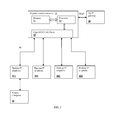
Figure 1 is a block diagram of a telephone system in accordance with an embodiment of the present invention; -
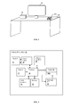
Figure 2 is a pictorial diagram showing arrangement of components of the telephone system ofFigure 1 within a building; -
Figure 3 is a block diagram depicting details ofdesktop IP telephones 10A-10D ofFigure 1 ; -
Figure 4 is a flowchart depicting a method of operation ofIP telephones 10A-10D of -
Figure 1 in accordance with an embodiment of the present invention; and -
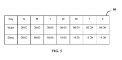
Figure 5 is a user interface display that may be provided on the display ofIP telephones 10A-10D ofFigure 1 , in accordance with an embodiment of the present invention. - The present invention encompasses network protocol telephones and methods, including IP telephones, along with telephone systems including network protocol telephones. The network protocol telephones include power management capability in which a low-power operating mode is initiated either by a scheduled timer, a command send from a central telephone controller, an indication of proximity of a user received from some other device, activation of a special key or special key combination/sequence that places the network protocol telephone in a low-power operating mode, or the like. The telephone exits the low-power operating mode in response to user activity, an indication of user proximity received from the other device, according to a scheduled wake-up time, or the like. The above operation, in particular the scheduled operation in which large numbers of telephones in a hotel or office may be de-activated when offices or hotel rooms are unoccupied, represents a significant energy (and therefore cost) savings to a business. The features may also be used in a home or other non-controller based environment to provide energy savings, as well.
- With reference now to the figures, and in particular with reference to
Figure 1 , an IP telephone system in accordance with an embodiment of the present invention is shown. The depicted embodiment is not intended to be limiting, but only exemplary of the type of telephone system to which the methods and structures of the present invention may be applied. Multipledesktop IP telephones 10A-10D are coupled to an IP phonecentral controller 12 by individual local-area network (LAN)connections 16. TheLAN connection 16 may be 10/100, gigabit connection, or the like. TheLAN connection 16 is in turn coupled to a wide-area network (WAN) connection WAN, through which a remote gateway such as a voice-over Internet protocol (VOIP)gateway 18 can be addressed. As will be explained in further detail below, IP phonecentral controller 12, and in some embodimentspersonal computer 14 play a role in activating and de-activating one or more power-savings modes ofdesktop IP telephones 10A-10D. Program instructions are provided to implement software algorithms and are stored within amemory 11 of IP phonecentral controller 12. The program instructions are executed by aprocessor 13, to provide such functions as a scheduler and messaging functionality as described in further detail below, by communicating withIP telephones 10A-10D viaLAN interfaces 15. TheLAN interface 15 may be 10/100, Gigabit (10/100/1000) LAN interface, or the like. - Referring now to
Figure 2 , an arrangement of components within the telephone system ofFigure 1 are shown in the form of an office arrangement.Personal computer 14 is connected to amonitor 22 and is proximate todesktop IP telephone 10A, e.g.,personal computer 14 anddesktop IP telephone 10A are located on thesame desk 20 in the same office. Therefore, a "proximity" association can be made between user activity onpersonal computer 14 and expectations that the same user may need to operatedesktop IP telephone 10A. The proximity association may alternatively be an "ownership" association, e.g.,telephone 10A is used by person A andpersonal computer 14 is used by person A, even though they are in someone separate locations, or are surrounded by many other devices in the same location, such as in a telephone bullpen. The use of an association such as those described above in power management ofdesktop IP telephone 10A will be described in further detail below. - Referring now to
Figure 3 , details of adesktop IP telephone 10, which implementsIP telephones 10A-10D ofFigure 1 as described above, are shown.Desktop IP telephone 10 is controlled by aprocessor 20 that executes program code stored inmemory 32 to provide various functions of thedesktop IP telephone 10. The depicted example is only illustrative and multiple processors can be provided for different functions withindesktop IP telephone 10. However, a single processor implementation has been shown for clarity. Ahandset 31 is interfaced through anaudio codec circuit 33 toprocessor 30 so that audio information received from a microphone in the handset can be converted byaudio codec 33 to information that can be communicated overLAN 16 ofFigure 1 by Ethernetinterface 35. Information received from Ethernetinterface 35 is also converted byaudio codec 33 to audio signals provided to an output transducer (speaker) ofhandset 31.Processor 30 in combination withaudio codec 33, implements a protocol such as Session Initiation Protocol (SIP) or other proprietary protocol to support a telephone connection betweenVOIP gateway 18 anddesktop IP telephone 10. -
Processor 30 also controls energy management states withindesktop IP telephone 10. This may include such things as disabling abacklight power supply 36 that provides power to a backlight withindisplay 34 and sending commands to Ethernetinterface 35 to place Ethernetinterface 35 and the connection in a power-down state. Theprocessor 30 may further control other power down functions including, but not limited to, disabling thedisplay driver circuitry 34A to remove any information/text on thedisplay 34 itself, powering down LED indicators (such as message waiting indicator), powering down audio circuitry including a digital signal processor, etc.Desktop IP telephone 10 also includes akeypad 37 for providing standard and special telephone button functionality. For example, thekeypad 37 may have a button for placing thedesktop IP telephone 10 in an energy savings mode.Desktop IP telephone 10 may also include a USB interface 38 or another suitable interface through which a connection can be established to another device such aspersonal computer 14, in order to receive proximity or absence indications as mentioned above. Such indications can also be provided via packets received at Ethernetinterface 35 that originate over a network connection ofpersonal computer 14 or from a service with whichpersonal computer 14 is interacting, such as an Internet messaging service. -
Desktop IP telephone 10 implements at least one low-power operating mode in accordance with an embodiment of the present invention, and in the exemplary embodiment described below, implements a deep sleep mode of operation in which Ethernetinterface 35,display 34,backlight power supply 36,audio codec 33, and LED indicators are disabled. In accordance with one embodiment, theprocessor 30 andmemory 32 remained powered. By keeping power to thememory 32, thedesktop IP telephone 10 will not have to reboot and download software from the IP phonecentral controller 12 when coming out of deep sleep mode. Further, by powering theprocessor 30, a real time clock of thedesktop IP telephone 10 can continue to function.Keypad 37 is scanned to determine if buttons are pressed (including the hook switch activated by handset 31) andprocessor 30 will generally enter periodic idle or sleep modes except when detecting activity, or when a wakeup timer has elapsed. The states of any deactivated devices are generally stored and then restored when the low-power operating mode is terminated. In a light sleep mode of operation, displaybacklight power supply 36,audio codec 33, and optionally display 34 along with any associated status LEDs are de-activated, butEthernet Interface 35 is maintained in an active state so thatdesktop IP telephone 10 can be restored to full-power operating mode in response to an incoming request such as a telephone call, or other interactive function such as text notifications provided to display 34 or status changes indicated by an LED, for example when a message has been left at a hotel lobby. - Referring now to
Figure 4 , a method of energy management ofdesktop IP telephones 10A-10D in the system ofFigure 1 is shown. TheIP telephones 10A-10D are initially powered-up (Step 40). Next, the network (LAN) interface of thedesktop IP telephones 10A-10D are initialized and connections are established to the IP phone central controller 12 (Step 41). Upon initial power-on and connection to the IP phonecentral controller 12, any configuration (and/or program code) that is loaded from IP phonecentral controller 12 is downloaded todesktop IP telephones 10A-10D. If a message is received from thecentral controller 12 via the LAN interface setting sleep/wake times fordesktop IP telephones 10A-10D (decision 42), the sleep/wake times are stored inIP telephones 10A-10D and the respective timers as implemented byprocessor 30 ofFigure 3 are set (step 43). If a user edits the sleep/wake times (decision 44) at one ofdesktop IP telephones 10A-10D, the values are change to customize them for the individual one ofdesktop IP telephones 10A-10D (step 45). In accordance with one embodiment, the user may edit the sleep/wake times (decision 44) at one ofdesktop IP telephones 10A-10D by pressing one or more buttons on thekeypad 37 to place a specifieddesktop IP telephones 10A-10D in sleep mode. - If a user enters a sleep command (special key or key combo/sequence or the sleep timer is activated (decision 46)) then the corresponding one of
desktop IP telephones 10A-10D enters deep sleep mode (step 47). The telephone remains in deep sleep mode (step 47) until a user activates the telephone or the wake time is reached (decision 48), at which time the above-described sequence is repeated fromstep 41 so that the network connection is initialized, but a state bit, generally provided byprocessor 30, differentiates from a pure power up restart, so thatstep 40 is not repeated when exiting the deep sleep mode. - In the illustrative example, light sleep mode (step 50) is activated in response to an indication that the user is absent from the telephone location, for example by an Internet messenger presence state that indicates the user is absent (decision 49). A resident application may be provided on
personal computer 14 to poll for the presence information and send it to an application programming interface (API) of the telephone. Alternatively USB interface 38 ofFigure 3 might be coupled topersonal computer 14 ofFigure 1 and receive a power management or other presence indication that indicates todesktop IP telephone 10A that the low-power operating mode should be activated or deactivated. The light sleep mode is maintained until the user activates the telephone or the presence status changes to "present" (step 51). Unless the power management scheme is disabled (step 52), the process of steps 40-52 is repeated. - In the event that power is lost to the
IP telephone 10A-10D during the deep or light sleep mode, theIP telephone 10A-10D will power up to full operating state when power is restored by repeating the above sequence starting atstep 41. - The above-depicted flow is only one example of a combination of deep sleep and light sleep modes that may be implemented in accordance with the present invention. The particular communications, actions or timeouts that cause activation and de-activation of the low-power operating modes as depicted above are not limiting and other combinations are contemplated by the present invention, including activation/deactivation of the light sleep mode by manual means. In the context of the present invention, it is understood that "low-power operating mode" indicates both light and deep sleep modes, and that the telephone does not need to be "operating", at least with respect to providing voice connections or network connections in order to be in an "operating mode", including the low-power operating mode(s) of the present invention.
- Referring now to
Figure 5 , a user interface that may be provided by a table 60 displayed ondisplay 34 ofFigure 3 and interacted with viakeypad 37 ofFigure 3 is shown. The depicted table 60 shows a set of Wake times and Sleep times in 24-hour format that can be transmitted from IP phonecentral controller 12 and customized (via keypad 37) at each individual IP telephone by the corresponding user. Such customization permits, for example in an office scenario, a worker to set their desktop IP telephone to be active during the times they are usually present at work. Alternatively, table 50 might form part of an HTML page served by an IP telephone and accessible viapersonal computer 14, either via the LAN or via USB interface 38 to provide editing of the Wake and Sleep times, as well as other features of the telephone. Further, via any of the user interfaces above, it is contemplated that the user may customize the low-power operating modes so that the particular features disabled for each mode may be set by the user. For example, in one system or station it might be necessary or desirable to disable only the backlight in deep sleep mode, but leave the display active without the backlight. In another application, or at another telephone station, might be acceptable to disable both the display and the backlight in deep sleep mode. - While the Sleep and Wake functions can be commanded by timer values as described above, the Sleep time may be immediate or "now", as provided by a special command or time value. Such a command is very useful in hotel applications, in which a property management system (PMS) may be coupled to the telephone system. The PMS can provide indications to IP phone
central controller 12 or toindividual IP telephones 10A-10D that certain rooms are occupied/unoccupied and therefore the telephones in unoccupied rooms can be placed in deep sleep mode. - This disclosure provides exemplary embodiments of the present invention. The scope of the present invention is not limited by these exemplary embodiments. Numerous variations, whether explicitly provided for by the specification or implied by the specification, such as variations in structure, dimension, type of material and manufacturing process may be implemented by one of skill in the art in view of this disclosure.
Claims (15)
- A desktop network protocol telephone set, comprising:a network interface for connecting the telephone set to a local area network;an audio interface for providing audio signals to and from a handset of the telephone set;a processing circuit responsive to communications from the network interface; anda control circuit for selecting between a full power operating mode of the telephone set and a low-power operating mode of the telephone set, wherein in the low-power operating mode, at least a portion of the telephone set is disabled.
- The desktop network protocol telephone set of claim 1, wherein the telephone set comprises a display having a backlight, wherein the control circuit further selects between a first low-power operating mode and a second low-power operating mode, wherein in the first low-power operating mode the network interface is enabled and the backlight is disabled, and wherein in the second low-power operating mode both the network interface and the backlight are disabled.
- The desktop network protocol telephone set of claim 2, wherein in the second low-power operating mode at least one of LED indicators, display circuitry, or audio circuitry is further disabled, and optionally wherein the message further includes a wake time for the telephone set to exit the low-power operating mode, and further optionally wherein the control circuit implements an interactive editor, whereby at least one of the wake time or the sleep time can be changed in conformity with user input received by the telephone set.
- The desktop network protocol telephone set of claim 1, wherein a message received from a central network telephone controller via the network interface indicates a sleep time for setting the low-power operating mode, and optionally wherein the sleep time is an immediate sleep time, wherein the message is interpreted by the control circuit as a command to enter the low-power operating mode without delay.
- The desktop network protocol telephone set of claim 1, further comprising at least one button coupled to the control circuit for manual selection of the low-power operating mode by a user.
- The desktop network protocol telephone set of claim 1, further comprising a connection to a personal computer, an indication communicated from the personal computer coupled to the telephone set indicating the low-power operating mode.
- A method of operation of a desktop network protocol telephone set coupled to a local area network by a network interface, comprising:first receiving first network transmissions from the local area network corresponding to received audio signals;first converting the first network transmissions to a first audio signal provided to a handset of the telephone set;second receiving a second audio signal from the handset;second converting the second audio signal to second network transmissions and providing them to the network interface;third receiving an indication that a user of the telephone set is not expected to be or is not in proximity to the telephone set; andselecting between a full power operating mode of the telephone set and a low-power operating mode of the telephone set in response to the indication received by the third receiving, wherein in the low-power operating mode, at least a portion of the telephone set is disabled.
- The method of claim 7, wherein the telephone set includes a display having a backlight, wherein the selecting further selects between a first low-power operating mode as the low-power operating mode and a second low-power operating mode, wherein in the first low-power operating mode the network interface is enabled and the backlight is disabled, and wherein in the second low-power operating mode both the network interface and the backlight are disabled, and optionally wherein in the second low-power operating mode at least one of LED indicators, display circuitry, or audio circuitry is further disabled.
- The method of claim 7, wherein the third receiving receives a message from a central network telephone controller via the network interface, that indicates a sleep time at which the user is expected to be away from the telephone set and that the low-power operating mode can be selected.
- The method of claim 9, wherein the message further includes a wake time for the telephone set to exit the low-power operating mode, and wherein the method further comprises:determining when the wake time has been reached; andexiting the low-power operating mode in response to the determining that the wake time has been reached.
- The method of claim 10, further comprising:providing an interactive editor using a display of the telephone set;receiving user input for changing at least one of the wake time or the sleep time; andmodifying the at least one of the wake time or the sleep time in conformity with the user input.
- The method of claim 11, wherein the sleep time is an immediate sleep time, and wherein the method further comprises interpreting the message as a command to enter the low-power operating mode without delay.
- The method of claim 7, wherein the third receiving receives a user input selecting the low-power operating mode, and wherein the selecting is performed in response to receiving the user input.
- The method of claim 7, wherein the third receiving receives a communication from a personal computer coupled to the telephone set and located proximate the telephone set, wherein the communication provides the indication that the user of the telephone set is not expected to be or is not in proximity to the telephone set.
- A network protocol telephone system, comprising:a central controller for controlling the telephone system;a plurality of desktop network protocol telephone sets coupled to the central controller via network interfaces of the telephone sets, and wherein the central controller sends commands to the telephone sets to place the telephone sets in a low-power operating mode according to a schedule of times that the telephone sets are expected to not be in use, and optionally wherein the low-power operating mode disables a network interface of the telephone sets, wherein the central controller further communicates a wake-up time to the telephone sets, and wherein the telephone sets include an internal timer that determines when the wake-up time has been reached and command the telephone sets to exit the low-power operating mode.
Applications Claiming Priority (1)
| Application Number | Priority Date | Filing Date | Title |
|---|---|---|---|
| US12/455,909 US8515340B2 (en) | 2009-06-08 | 2009-06-08 | Power management in an internet protocol (IP) telephone |
Publications (2)
| Publication Number | Publication Date |
|---|---|
| EP2262207A1 true EP2262207A1 (en) | 2010-12-15 |
| EP2262207B1 EP2262207B1 (en) | 2012-01-18 |
Family
ID=42558562
Family Applications (1)
| Application Number | Title | Priority Date | Filing Date |
|---|---|---|---|
| EP10154622A Active EP2262207B1 (en) | 2009-06-08 | 2010-02-25 | Power management in an internet protocol (IP) telephone |
Country Status (5)
| Country | Link |
|---|---|
| US (1) | US8515340B2 (en) |
| EP (1) | EP2262207B1 (en) |
| CN (1) | CN101909101A (en) |
| AT (1) | ATE542360T1 (en) |
| CA (1) | CA2701280C (en) |
Families Citing this family (16)
| Publication number | Priority date | Publication date | Assignee | Title |
|---|---|---|---|---|
| US8352769B1 (en) | 2009-02-09 | 2013-01-08 | Cisco Technology, Inc. | System and method for querying for energy data in a network environment |
| US8732501B1 (en) | 2009-02-09 | 2014-05-20 | Cisco Technology, Inc. | System and method for intelligent energy management in a network environment |
| US9762748B2 (en) * | 2009-06-08 | 2017-09-12 | Mitel Networks Corporation | Power management in an internet protocol (IP) telephone |
| US8996900B2 (en) | 2010-02-04 | 2015-03-31 | Cisco Technology, Inc. | System and method for managing power consumption in data propagation environments |
| US9026812B2 (en) * | 2010-06-29 | 2015-05-05 | Cisco Technology, Inc. | System and method for providing intelligent power management in a network environment |
| US8849473B2 (en) | 2011-08-17 | 2014-09-30 | Cisco Technology, Inc. | System and method for notifying and for controlling power demand |
| US9058167B2 (en) | 2011-09-06 | 2015-06-16 | Cisco Technology, Inc. | Power conservation in a distributed digital video recorder/content delivery network system |
| US20130132745A1 (en) | 2011-11-22 | 2013-05-23 | Cisco Technology Inc. | System and method for network enabled wake for networks |
| US9141169B2 (en) | 2012-01-20 | 2015-09-22 | Cisco Technology, Inc. | System and method to conserve power in an access network without loss of service quality |
| CN104838636B (en) * | 2012-10-29 | 2018-10-16 | 高通股份有限公司 | Ethernet over USB interface with full-duplex differential pair |
| US9727110B2 (en) * | 2012-11-07 | 2017-08-08 | Dell Products L.P. | Optimized power over ethernet power distribution system |
| JP5536253B1 (en) * | 2013-04-30 | 2014-07-02 | Necインフロンティア株式会社 | Button telephone system, control method, terminal, and program |
| US9958924B2 (en) | 2013-08-28 | 2018-05-01 | Cisco Technology, Inc. | Configuration of energy savings |
| US9288616B2 (en) * | 2013-10-10 | 2016-03-15 | Pushd, Inc. | Automated electronic reminders for a mobile user |
| US9445173B2 (en) * | 2014-03-10 | 2016-09-13 | Infineon Technologies Ag | System and method for a transducer system with wakeup detection |
| US10235516B2 (en) | 2016-05-10 | 2019-03-19 | Cisco Technology, Inc. | Method for authenticating a networked endpoint using a physical (power) challenge |
Citations (3)
| Publication number | Priority date | Publication date | Assignee | Title |
|---|---|---|---|---|
| WO2001015416A1 (en) * | 1999-08-24 | 2001-03-01 | Elisa Communications Oyj | Method for controlling a personal number service |
| US20060023698A1 (en) * | 2004-07-15 | 2006-02-02 | Paul Shore | Method and system for a gigabit Ethernet IP telephone chip with integrated DDR interface |
| WO2007033880A1 (en) * | 2005-09-21 | 2007-03-29 | Siemens Enterprise Communications Gmbh & Co. Kg | Method and device for energy-savingly operating a communication terminal |
Family Cites Families (7)
| Publication number | Priority date | Publication date | Assignee | Title |
|---|---|---|---|---|
| WO2001099392A1 (en) * | 2000-06-21 | 2001-12-27 | Seiko Epson Corporation | Mobile telephone and radio communication device cooperatively processing incoming call |
| US7236475B2 (en) * | 2002-02-06 | 2007-06-26 | Ntt Docomo, Inc. | Using subnet relations to conserve power in a wireless communication device |
| US7123286B2 (en) * | 2003-11-14 | 2006-10-17 | Lucent Technologies Inc. | Presence detection for IP telephony |
| US7769415B2 (en) * | 2004-11-24 | 2010-08-03 | Research In Motion Limited | System and method for activating a communication device based on usage information |
| US7509509B2 (en) * | 2006-02-13 | 2009-03-24 | International Business Machines Corporation | Method and mechanism for cataloguing information on devices in a computing system |
| US8068925B2 (en) * | 2007-06-28 | 2011-11-29 | Apple Inc. | Dynamic routing of audio among multiple audio devices |
| US8494574B2 (en) * | 2008-10-24 | 2013-07-23 | Centurylink Intellectual Property Llc | System and method for controlling a feature of a telecommunications device based on the body temperature of a user |
-
2009
- 2009-06-08 US US12/455,909 patent/US8515340B2/en active Active
-
2010
- 2010-02-25 AT AT10154622T patent/ATE542360T1/en active
- 2010-02-25 EP EP10154622A patent/EP2262207B1/en active Active
- 2010-04-22 CA CA2701280A patent/CA2701280C/en active Active
- 2010-06-08 CN CN2010101983789A patent/CN101909101A/en active Pending
Patent Citations (3)
| Publication number | Priority date | Publication date | Assignee | Title |
|---|---|---|---|---|
| WO2001015416A1 (en) * | 1999-08-24 | 2001-03-01 | Elisa Communications Oyj | Method for controlling a personal number service |
| US20060023698A1 (en) * | 2004-07-15 | 2006-02-02 | Paul Shore | Method and system for a gigabit Ethernet IP telephone chip with integrated DDR interface |
| WO2007033880A1 (en) * | 2005-09-21 | 2007-03-29 | Siemens Enterprise Communications Gmbh & Co. Kg | Method and device for energy-savingly operating a communication terminal |
Also Published As
| Publication number | Publication date |
|---|---|
| CA2701280C (en) | 2013-10-22 |
| EP2262207B1 (en) | 2012-01-18 |
| US8515340B2 (en) | 2013-08-20 |
| CN101909101A (en) | 2010-12-08 |
| US20100309904A1 (en) | 2010-12-09 |
| ATE542360T1 (en) | 2012-02-15 |
| CA2701280A1 (en) | 2010-12-08 |
Similar Documents
| Publication | Publication Date | Title |
|---|---|---|
| EP2262207B1 (en) | Power management in an internet protocol (IP) telephone | |
| CN102165755B (en) | Method, telephone, telecommunication system and device for controlling power consumption of a telephone | |
| CN100420158C (en) | Method and apparatus for conserving power in an integrated electronic device including a personal digital assistant and a wireless telephone | |
| US5790649A (en) | Call transfer system and electronic mail transfer system | |
| US20070037610A1 (en) | Methods and apparatus for conserving battery power in a cellular or portable telephone | |
| EP0664632A2 (en) | Telephone controller | |
| CN103309428B (en) | Information processing method and electronic equipment | |
| US20040097218A1 (en) | Intelligent cellular telephone function | |
| US9762748B2 (en) | Power management in an internet protocol (IP) telephone | |
| CA2703713C (en) | Device and method for preventing ion build-up in liquid crystal displays | |
| CN1132989A (en) | wireless communication device | |
| JP2000287240A (en) | Key telephone system | |
| JP2003046665A (en) | IP multifunctional telephone system | |
| CN101268679B (en) | Method and device for energy-saving operation of communication terminal equipment | |
| JP2005101921A (en) | Ip telephone terminal and ip telephone system | |
| JP2000287233A (en) | Telephone system | |
| JP2003263251A (en) | Information processing device with wireless communication function | |
| KR100818449B1 (en) | Communication system having a voice call response function in power saving mode and a voice call response method using the same | |
| JP2000287232A (en) | Telephone system | |
| JP5082945B2 (en) | IP telephone and control method thereof | |
| JP2005333410A (en) | Telephone exchange equipment | |
| JP2008092181A (en) | Telephone control system | |
| KR100407347B1 (en) | Device for safety calling occasion system halt in complex phone and method thereof | |
| KR20050043294A (en) | Method and apparutus for controlling power in mobile phone | |
| JP2001339523A (en) | Remote operation device with interphone function |
Legal Events
| Date | Code | Title | Description |
|---|---|---|---|
| PUAI | Public reference made under article 153(3) epc to a published international application that has entered the european phase |
Free format text: ORIGINAL CODE: 0009012 |
|
| AK | Designated contracting states |
Kind code of ref document: A1 Designated state(s): AT BE BG CH CY CZ DE DK EE ES FI FR GB GR HR HU IE IS IT LI LT LU LV MC MK MT NL NO PL PT RO SE SI SK SM TR |
|
| AX | Request for extension of the european patent |
Extension state: AL BA RS |
|
| 17P | Request for examination filed |
Effective date: 20110610 |
|
| RIC1 | Information provided on ipc code assigned before grant |
Ipc: H04M 1/253 20060101AFI20110715BHEP |
|
| GRAP | Despatch of communication of intention to grant a patent |
Free format text: ORIGINAL CODE: EPIDOSNIGR1 |
|
| GRAS | Grant fee paid |
Free format text: ORIGINAL CODE: EPIDOSNIGR3 |
|
| GRAA | (expected) grant |
Free format text: ORIGINAL CODE: 0009210 |
|
| AK | Designated contracting states |
Kind code of ref document: B1 Designated state(s): AT BE BG CH CY CZ DE DK EE ES FI FR GB GR HR HU IE IS IT LI LT LU LV MC MK MT NL NO PL PT RO SE SI SK SM TR |
|
| REG | Reference to a national code |
Ref country code: GB Ref legal event code: FG4D |
|
| REG | Reference to a national code |
Ref country code: CH Ref legal event code: EP |
|
| REG | Reference to a national code |
Ref country code: AT Ref legal event code: REF Ref document number: 542360 Country of ref document: AT Kind code of ref document: T Effective date: 20120215 Ref country code: IE Ref legal event code: FG4D |
|
| REG | Reference to a national code |
Ref country code: DE Ref legal event code: R096 Ref document number: 602010000664 Country of ref document: DE Effective date: 20120322 |
|
| REG | Reference to a national code |
Ref country code: NL Ref legal event code: VDEP Effective date: 20120118 |
|
| LTIE | Lt: invalidation of european patent or patent extension |
Effective date: 20120118 |
|
| PG25 | Lapsed in a contracting state [announced via postgrant information from national office to epo] |
Ref country code: NL Free format text: LAPSE BECAUSE OF FAILURE TO SUBMIT A TRANSLATION OF THE DESCRIPTION OR TO PAY THE FEE WITHIN THE PRESCRIBED TIME-LIMIT Effective date: 20120118 Ref country code: BG Free format text: LAPSE BECAUSE OF FAILURE TO SUBMIT A TRANSLATION OF THE DESCRIPTION OR TO PAY THE FEE WITHIN THE PRESCRIBED TIME-LIMIT Effective date: 20120418 Ref country code: LT Free format text: LAPSE BECAUSE OF FAILURE TO SUBMIT A TRANSLATION OF THE DESCRIPTION OR TO PAY THE FEE WITHIN THE PRESCRIBED TIME-LIMIT Effective date: 20120118 Ref country code: BE Free format text: LAPSE BECAUSE OF FAILURE TO SUBMIT A TRANSLATION OF THE DESCRIPTION OR TO PAY THE FEE WITHIN THE PRESCRIBED TIME-LIMIT Effective date: 20120118 Ref country code: NO Free format text: LAPSE BECAUSE OF FAILURE TO SUBMIT A TRANSLATION OF THE DESCRIPTION OR TO PAY THE FEE WITHIN THE PRESCRIBED TIME-LIMIT Effective date: 20120418 Ref country code: IS Free format text: LAPSE BECAUSE OF FAILURE TO SUBMIT A TRANSLATION OF THE DESCRIPTION OR TO PAY THE FEE WITHIN THE PRESCRIBED TIME-LIMIT Effective date: 20120518 Ref country code: HR Free format text: LAPSE BECAUSE OF FAILURE TO SUBMIT A TRANSLATION OF THE DESCRIPTION OR TO PAY THE FEE WITHIN THE PRESCRIBED TIME-LIMIT Effective date: 20120118 |
|
| PG25 | Lapsed in a contracting state [announced via postgrant information from national office to epo] |
Ref country code: PT Free format text: LAPSE BECAUSE OF FAILURE TO SUBMIT A TRANSLATION OF THE DESCRIPTION OR TO PAY THE FEE WITHIN THE PRESCRIBED TIME-LIMIT Effective date: 20120518 Ref country code: LV Free format text: LAPSE BECAUSE OF FAILURE TO SUBMIT A TRANSLATION OF THE DESCRIPTION OR TO PAY THE FEE WITHIN THE PRESCRIBED TIME-LIMIT Effective date: 20120118 Ref country code: PL Free format text: LAPSE BECAUSE OF FAILURE TO SUBMIT A TRANSLATION OF THE DESCRIPTION OR TO PAY THE FEE WITHIN THE PRESCRIBED TIME-LIMIT Effective date: 20120118 Ref country code: GR Free format text: LAPSE BECAUSE OF FAILURE TO SUBMIT A TRANSLATION OF THE DESCRIPTION OR TO PAY THE FEE WITHIN THE PRESCRIBED TIME-LIMIT Effective date: 20120419 Ref country code: FI Free format text: LAPSE BECAUSE OF FAILURE TO SUBMIT A TRANSLATION OF THE DESCRIPTION OR TO PAY THE FEE WITHIN THE PRESCRIBED TIME-LIMIT Effective date: 20120118 |
|
| REG | Reference to a national code |
Ref country code: AT Ref legal event code: MK05 Ref document number: 542360 Country of ref document: AT Kind code of ref document: T Effective date: 20120118 |
|
| PG25 | Lapsed in a contracting state [announced via postgrant information from national office to epo] |
Ref country code: CY Free format text: LAPSE BECAUSE OF FAILURE TO SUBMIT A TRANSLATION OF THE DESCRIPTION OR TO PAY THE FEE WITHIN THE PRESCRIBED TIME-LIMIT Effective date: 20120118 Ref country code: MC Free format text: LAPSE BECAUSE OF NON-PAYMENT OF DUE FEES Effective date: 20120229 |
|
| PG25 | Lapsed in a contracting state [announced via postgrant information from national office to epo] |
Ref country code: DK Free format text: LAPSE BECAUSE OF FAILURE TO SUBMIT A TRANSLATION OF THE DESCRIPTION OR TO PAY THE FEE WITHIN THE PRESCRIBED TIME-LIMIT Effective date: 20120118 Ref country code: SE Free format text: LAPSE BECAUSE OF FAILURE TO SUBMIT A TRANSLATION OF THE DESCRIPTION OR TO PAY THE FEE WITHIN THE PRESCRIBED TIME-LIMIT Effective date: 20120118 Ref country code: CZ Free format text: LAPSE BECAUSE OF FAILURE TO SUBMIT A TRANSLATION OF THE DESCRIPTION OR TO PAY THE FEE WITHIN THE PRESCRIBED TIME-LIMIT Effective date: 20120118 Ref country code: RO Free format text: LAPSE BECAUSE OF FAILURE TO SUBMIT A TRANSLATION OF THE DESCRIPTION OR TO PAY THE FEE WITHIN THE PRESCRIBED TIME-LIMIT Effective date: 20120118 Ref country code: EE Free format text: LAPSE BECAUSE OF FAILURE TO SUBMIT A TRANSLATION OF THE DESCRIPTION OR TO PAY THE FEE WITHIN THE PRESCRIBED TIME-LIMIT Effective date: 20120118 Ref country code: SI Free format text: LAPSE BECAUSE OF FAILURE TO SUBMIT A TRANSLATION OF THE DESCRIPTION OR TO PAY THE FEE WITHIN THE PRESCRIBED TIME-LIMIT Effective date: 20120118 |
|
| REG | Reference to a national code |
Ref country code: IE Ref legal event code: MM4A |
|
| PLBE | No opposition filed within time limit |
Free format text: ORIGINAL CODE: 0009261 |
|
| STAA | Information on the status of an ep patent application or granted ep patent |
Free format text: STATUS: NO OPPOSITION FILED WITHIN TIME LIMIT |
|
| PG25 | Lapsed in a contracting state [announced via postgrant information from national office to epo] |
Ref country code: SK Free format text: LAPSE BECAUSE OF FAILURE TO SUBMIT A TRANSLATION OF THE DESCRIPTION OR TO PAY THE FEE WITHIN THE PRESCRIBED TIME-LIMIT Effective date: 20120118 Ref country code: IT Free format text: LAPSE BECAUSE OF FAILURE TO SUBMIT A TRANSLATION OF THE DESCRIPTION OR TO PAY THE FEE WITHIN THE PRESCRIBED TIME-LIMIT Effective date: 20120118 |
|
| 26N | No opposition filed |
Effective date: 20121019 |
|
| PG25 | Lapsed in a contracting state [announced via postgrant information from national office to epo] |
Ref country code: IE Free format text: LAPSE BECAUSE OF NON-PAYMENT OF DUE FEES Effective date: 20120225 Ref country code: AT Free format text: LAPSE BECAUSE OF FAILURE TO SUBMIT A TRANSLATION OF THE DESCRIPTION OR TO PAY THE FEE WITHIN THE PRESCRIBED TIME-LIMIT Effective date: 20120118 |
|
| REG | Reference to a national code |
Ref country code: DE Ref legal event code: R097 Ref document number: 602010000664 Country of ref document: DE Effective date: 20121019 |
|
| PG25 | Lapsed in a contracting state [announced via postgrant information from national office to epo] |
Ref country code: MK Free format text: LAPSE BECAUSE OF FAILURE TO SUBMIT A TRANSLATION OF THE DESCRIPTION OR TO PAY THE FEE WITHIN THE PRESCRIBED TIME-LIMIT Effective date: 20120118 |
|
| PG25 | Lapsed in a contracting state [announced via postgrant information from national office to epo] |
Ref country code: ES Free format text: LAPSE BECAUSE OF FAILURE TO SUBMIT A TRANSLATION OF THE DESCRIPTION OR TO PAY THE FEE WITHIN THE PRESCRIBED TIME-LIMIT Effective date: 20120429 |
|
| PG25 | Lapsed in a contracting state [announced via postgrant information from national office to epo] |
Ref country code: MT Free format text: LAPSE BECAUSE OF FAILURE TO SUBMIT A TRANSLATION OF THE DESCRIPTION OR TO PAY THE FEE WITHIN THE PRESCRIBED TIME-LIMIT Effective date: 20120118 |
|
| PG25 | Lapsed in a contracting state [announced via postgrant information from national office to epo] |
Ref country code: TR Free format text: LAPSE BECAUSE OF FAILURE TO SUBMIT A TRANSLATION OF THE DESCRIPTION OR TO PAY THE FEE WITHIN THE PRESCRIBED TIME-LIMIT Effective date: 20120118 |
|
| PG25 | Lapsed in a contracting state [announced via postgrant information from national office to epo] |
Ref country code: LU Free format text: LAPSE BECAUSE OF NON-PAYMENT OF DUE FEES Effective date: 20120225 Ref country code: SM Free format text: LAPSE BECAUSE OF FAILURE TO SUBMIT A TRANSLATION OF THE DESCRIPTION OR TO PAY THE FEE WITHIN THE PRESCRIBED TIME-LIMIT Effective date: 20120118 |
|
| PG25 | Lapsed in a contracting state [announced via postgrant information from national office to epo] |
Ref country code: HU Free format text: LAPSE BECAUSE OF FAILURE TO SUBMIT A TRANSLATION OF THE DESCRIPTION OR TO PAY THE FEE WITHIN THE PRESCRIBED TIME-LIMIT Effective date: 20100225 |
|
| REG | Reference to a national code |
Ref country code: CH Ref legal event code: PL |
|
| PG25 | Lapsed in a contracting state [announced via postgrant information from national office to epo] |
Ref country code: LI Free format text: LAPSE BECAUSE OF NON-PAYMENT OF DUE FEES Effective date: 20140228 Ref country code: CH Free format text: LAPSE BECAUSE OF NON-PAYMENT OF DUE FEES Effective date: 20140228 |
|
| REG | Reference to a national code |
Ref country code: FR Ref legal event code: PLFP Year of fee payment: 7 |
|
| REG | Reference to a national code |
Ref country code: FR Ref legal event code: PLFP Year of fee payment: 8 |
|
| REG | Reference to a national code |
Ref country code: FR Ref legal event code: PLFP Year of fee payment: 9 |
|
| REG | Reference to a national code |
Ref country code: DE Ref legal event code: R082 Ref document number: 602010000664 Country of ref document: DE Representative=s name: VENNER SHIPLEY GERMANY LLP, DE Ref country code: DE Ref legal event code: R081 Ref document number: 602010000664 Country of ref document: DE Owner name: DIORITE TECHNOLOGY, LLC, MCKINNEY, US Free format text: FORMER OWNER: MITEL NETWORKS CORPORATION, OTTAWA, ONTARIO, CA |
|
| REG | Reference to a national code |
Ref country code: GB Ref legal event code: 732E Free format text: REGISTERED BETWEEN 20241205 AND 20241211 |
|
| PGFP | Annual fee paid to national office [announced via postgrant information from national office to epo] |
Ref country code: GB Payment date: 20260227 Year of fee payment: 17 |
|
| PGFP | Annual fee paid to national office [announced via postgrant information from national office to epo] |
Ref country code: DE Payment date: 20260227 Year of fee payment: 17 |
|
| PGFP | Annual fee paid to national office [announced via postgrant information from national office to epo] |
Ref country code: FR Payment date: 20260225 Year of fee payment: 17 |