EP2261838A2 - Scanner carrier apparatus - Google Patents
Scanner carrier apparatus Download PDFInfo
- Publication number
- EP2261838A2 EP2261838A2 EP10165440A EP10165440A EP2261838A2 EP 2261838 A2 EP2261838 A2 EP 2261838A2 EP 10165440 A EP10165440 A EP 10165440A EP 10165440 A EP10165440 A EP 10165440A EP 2261838 A2 EP2261838 A2 EP 2261838A2
- Authority
- EP
- European Patent Office
- Prior art keywords
- assembly
- scanner head
- document
- bogey
- scanner
- Prior art date
- Legal status (The legal status is an assumption and is not a legal conclusion. Google has not performed a legal analysis and makes no representation as to the accuracy of the status listed.)
- Granted
Links
Images




Classifications
-
- B—PERFORMING OPERATIONS; TRANSPORTING
- B43—WRITING OR DRAWING IMPLEMENTS; BUREAU ACCESSORIES
- B43M—BUREAU ACCESSORIES NOT OTHERWISE PROVIDED FOR
- B43M3/00—Devices for inserting documents into envelopes
-
- G—PHYSICS
- G06—COMPUTING OR CALCULATING; COUNTING
- G06K—GRAPHICAL DATA READING; PRESENTATION OF DATA; RECORD CARRIERS; HANDLING RECORD CARRIERS
- G06K7/00—Methods or arrangements for sensing record carriers, e.g. for reading patterns
- G06K7/10—Methods or arrangements for sensing record carriers, e.g. for reading patterns by electromagnetic radiation, e.g. optical sensing; by corpuscular radiation
- G06K7/10544—Methods or arrangements for sensing record carriers, e.g. for reading patterns by electromagnetic radiation, e.g. optical sensing; by corpuscular radiation by scanning of the records by radiation in the optical part of the electromagnetic spectrum
- G06K7/10712—Fixed beam scanning
- G06K7/10762—Relative movement
-
- B—PERFORMING OPERATIONS; TRANSPORTING
- B07—SEPARATING SOLIDS FROM SOLIDS; SORTING
- B07C—POSTAL SORTING; SORTING INDIVIDUAL ARTICLES, OR BULK MATERIAL FIT TO BE SORTED PIECE-MEAL, e.g. BY PICKING
- B07C5/00—Sorting according to a characteristic or feature of the articles or material being sorted, e.g. by control effected by devices which detect or measure such characteristic or feature; Sorting by manually actuated devices, e.g. switches
- B07C5/34—Sorting according to other particular properties
- B07C5/342—Sorting according to other particular properties according to optical properties, e.g. colour
-
- G—PHYSICS
- G06—COMPUTING OR CALCULATING; COUNTING
- G06K—GRAPHICAL DATA READING; PRESENTATION OF DATA; RECORD CARRIERS; HANDLING RECORD CARRIERS
- G06K7/00—Methods or arrangements for sensing record carriers, e.g. for reading patterns
- G06K7/01—Details
- G06K7/015—Aligning or centering of the sensing device with respect to the record carrier
-
- G—PHYSICS
- G06—COMPUTING OR CALCULATING; COUNTING
- G06K—GRAPHICAL DATA READING; PRESENTATION OF DATA; RECORD CARRIERS; HANDLING RECORD CARRIERS
- G06K7/00—Methods or arrangements for sensing record carriers, e.g. for reading patterns
- G06K7/10—Methods or arrangements for sensing record carriers, e.g. for reading patterns by electromagnetic radiation, e.g. optical sensing; by corpuscular radiation
-
- H—ELECTRICITY
- H04—ELECTRIC COMMUNICATION TECHNIQUE
- H04N—PICTORIAL COMMUNICATION, e.g. TELEVISION
- H04N1/00—Scanning, transmission or reproduction of documents or the like, e.g. facsimile transmission; Details thereof
- H04N1/04—Scanning arrangements, i.e. arrangements for the displacement of active reading or reproducing elements relative to the original or reproducing medium, or vice versa
- H04N1/12—Scanning arrangements, i.e. arrangements for the displacement of active reading or reproducing elements relative to the original or reproducing medium, or vice versa using the sheet-feed movement or the medium-advance or the drum-rotation movement as the slow scanning component, e.g. arrangements for the main-scanning
- H04N1/121—Feeding arrangements
- H04N1/1215—Feeding using one or more cylindrical platens or rollers in the immediate vicinity of the main scanning line
-
- H—ELECTRICITY
- H04—ELECTRIC COMMUNICATION TECHNIQUE
- H04N—PICTORIAL COMMUNICATION, e.g. TELEVISION
- H04N1/00—Scanning, transmission or reproduction of documents or the like, e.g. facsimile transmission; Details thereof
- H04N1/04—Scanning arrangements, i.e. arrangements for the displacement of active reading or reproducing elements relative to the original or reproducing medium, or vice versa
- H04N1/12—Scanning arrangements, i.e. arrangements for the displacement of active reading or reproducing elements relative to the original or reproducing medium, or vice versa using the sheet-feed movement or the medium-advance or the drum-rotation movement as the slow scanning component, e.g. arrangements for the main-scanning
- H04N1/121—Feeding arrangements
- H04N1/1225—Means for maintaining contact between the sheet and the image sensor, e.g. pressing means
-
- H—ELECTRICITY
- H04—ELECTRIC COMMUNICATION TECHNIQUE
- H04N—PICTORIAL COMMUNICATION, e.g. TELEVISION
- H04N1/00—Scanning, transmission or reproduction of documents or the like, e.g. facsimile transmission; Details thereof
- H04N1/04—Scanning arrangements, i.e. arrangements for the displacement of active reading or reproducing elements relative to the original or reproducing medium, or vice versa
- H04N1/12—Scanning arrangements, i.e. arrangements for the displacement of active reading or reproducing elements relative to the original or reproducing medium, or vice versa using the sheet-feed movement or the medium-advance or the drum-rotation movement as the slow scanning component, e.g. arrangements for the main-scanning
- H04N1/126—Arrangements for the main scanning
- H04N1/128—Arrangements for the main scanning using a scanning head arranged for linear reciprocating motion
-
- H—ELECTRICITY
- H04—ELECTRIC COMMUNICATION TECHNIQUE
- H04N—PICTORIAL COMMUNICATION, e.g. TELEVISION
- H04N1/00—Scanning, transmission or reproduction of documents or the like, e.g. facsimile transmission; Details thereof
- H04N1/04—Scanning arrangements, i.e. arrangements for the displacement of active reading or reproducing elements relative to the original or reproducing medium, or vice versa
- H04N1/12—Scanning arrangements, i.e. arrangements for the displacement of active reading or reproducing elements relative to the original or reproducing medium, or vice versa using the sheet-feed movement or the medium-advance or the drum-rotation movement as the slow scanning component, e.g. arrangements for the main-scanning
- H04N1/126—Arrangements for the main scanning
- H04N1/129—Arrangements for the main scanning using an element rotating or oscillating about an axis not covered by any other group or code
-
- H—ELECTRICITY
- H04—ELECTRIC COMMUNICATION TECHNIQUE
- H04N—PICTORIAL COMMUNICATION, e.g. TELEVISION
- H04N1/00—Scanning, transmission or reproduction of documents or the like, e.g. facsimile transmission; Details thereof
- H04N1/04—Scanning arrangements, i.e. arrangements for the displacement of active reading or reproducing elements relative to the original or reproducing medium, or vice versa
- H04N1/203—Simultaneous scanning of two or more separate pictures, e.g. two sides of the same sheet
-
- H—ELECTRICITY
- H04—ELECTRIC COMMUNICATION TECHNIQUE
- H04N—PICTORIAL COMMUNICATION, e.g. TELEVISION
- H04N1/00—Scanning, transmission or reproduction of documents or the like, e.g. facsimile transmission; Details thereof
- H04N1/04—Scanning arrangements, i.e. arrangements for the displacement of active reading or reproducing elements relative to the original or reproducing medium, or vice versa
- H04N1/203—Simultaneous scanning of two or more separate pictures, e.g. two sides of the same sheet
- H04N1/2032—Simultaneous scanning of two or more separate pictures, e.g. two sides of the same sheet of two pictures corresponding to two sides of a single medium
-
- H—ELECTRICITY
- H04—ELECTRIC COMMUNICATION TECHNIQUE
- H04N—PICTORIAL COMMUNICATION, e.g. TELEVISION
- H04N2201/00—Indexing scheme relating to scanning, transmission or reproduction of documents or the like, and to details thereof
- H04N2201/04—Scanning arrangements
- H04N2201/0402—Arrangements not specific to a particular one of the scanning methods covered by groups H04N1/04 - H04N1/207
- H04N2201/0456—Arrangements not specific to a particular one of the scanning methods covered by groups H04N1/04 - H04N1/207 for maintaining a predetermined distance between the scanning elements and the picture-bearing surface
Definitions
- the present invention relates to apparatus for supporting a scanner in a paper handling system, for example in an inserter system used for inserting sheets of paper into an envelope for mailing.
- Scanners are typically arranged to read machine control data printed on sheets entering the paper handling system and suitable scanners may be bar code scanners, OCR readers, magnetic readers, cameras or any other reading devices.
- the control data thus read may provide information and instructions relevant to control of the flow of paper and the operation of the apparatus in dependence upon the control codes printed on the documents.
- scanners are rigidly mounted to the paper handling apparatus then their position must be manually adjusted at the beginning of a production run to accommodate different thicknesses, weights and sizes of paper, and to accommodate different positions of the control codes on the documents. It may also be necessary to adjust the distance of the scanner head face from the document to ensure correct focussing on the codes. Such manual adjustment is time consuming and subject to human error. The need for manual adjustment makes known optical scanner assemblies unsuitable for small scale use and particularly for use with a variety of different document types.
- US 5,171,980 describes an optical scanner apparatus for an inserter, comprising a support member rigidly fixed over a paper path in an inserter, and a mounting structure for a scanner head.
- the mounting structure is operatively coupled to the support member to allow position adjustments of the scanner in the transverse direction.
- a fixed reference for vertical movement is provided by linkage, and paper guides assist to maintain a fixed distance between the scanner head and document being scanned.
- the apparatus keeps the scanner head parallel to the paper path and a fixed distance from the document during scanning.
- this apparatus is bulky and less reliable and efficient than is desired.
- apparatus for supporting a scanner head comprising: a carrier assembly; a bogey assembly; and a scanner head assembly, wherein the scanner head assembly and the bogey assembly are both mounted on spring bearings on the carrier assembly such that they can both move in a vertical direction, and the scanner head assembly comprises two collinear vertical bearings which restrict movement of the scanner head assembly to vertical movement substantially perpendicular to a document path, and the bogey assembly comprises two laterally spaced independent bearings to allow rotational movement of the bogey assembly about the scanner head.
- the laterally spaced bearings are housed within cut-outs on the carrier assembly and the laterally spaced bearing points are disposed on opposed sides of the scanner head along the document path.
- the bogey assembly comprises at least two rollers laterally spaced on opposed sides of the scanner head along the document path.
- the bogey assembly may also comprise a lead roller at the input side of the document path which provides a clearance for passage of a document which clearance is larger than that provided by the first roller.
- the carrier assembly may comprise a first spring housing for a spring to provide a bias between the carrier assembly and the scanner head assembly toward the document path, and a second spring housing for a spring which provides a bias between the carrier assembly and the bogey assembly. Preferably there on each side of the scanner head.
- a guide tape is positioned so as to deflect a document travelling along the document path to contact the scanning face of the scanning head.
- a second scanner head is positioned below the document path and a second guide tape may be positioned so as to deflect a document travelling along the document path into contact with the second scanning head.
- Figure 1 shows the scanner carrier apparatus indicated generally at 1, in cross-section.
- a document 2 enters the apparatus 1 from the right-hand side and travels from right to left along a document path as indicated generally between arrows 9A and 9B, passing an upper scanner 3 and a lower scanner 4 which read optical marks or indices on respective sides of the document 2.
- a first, lead, roller 5 contacts the document 2 initially at the input to the apparatus and moves it further into the apparatus to engage with a second set of rollers 6.
- the second roller set 6 guides the document 2 into a document channel 7 so that it passes the scanners 3 and 4.
- Finally the document enters the nip of a third set of rollers 8 which drives it out of the apparatus in the direction of arrow 9B.
- the apparatus 1 comprises three interconnected but relatively moveable parts which will be referred to as a scanner head assembly 10, a bogey assembly 11 and a carrier assembly 12. These three parts are shown more clearly in the exploded view of Figure 3 , parts of which will also be referred to here.
- the head assembly 10 has a scanner mounting on its lower side to which a scanner 3 is fixed. It is in close proximity to two laterally spaced rotational bearings 13 in the bogey assembly 11. It is also attached to the carrier assembly 12 by two vertically spaced bearings 14 which constrain the head assembly 10 to vertical movement only. In this way the scanner 3 always has its lower scanning face held at the same angle to the document travelling through the apparatus, regardless of the height of the head assembly above the document path, and hence regardless of the thickness of the document 2.
- Each of the bearings 13 on the bogey assembly 11 is connected by a spring 15 to the carrier assembly 12.
- the head assembly 10 is connected to the carrier assembly 12 by a spring 16.
- the bogey assembly 11 and the head assembly 10, with the scanner 3 are biased in a downward direction (as shown in the figures) toward the face of the document 2.
- the bearings 13 on the bogey assembly 11 do not contact the head assembly 10 in the normal steady state condition because there is a clearance gap 21 ( Figures 1 and 2 ) between surfaces 24 of bearings 13 and surfaces 25 of head assembly 10.
- the bogey assembly 11 As the bogey assembly 11 lifts, and/or rotates on one or both of bearings 13, it also causes the head assembly 10 to rise in bearings 14 against the force of the spring 16. However the head assembly 10 is constrained by the linear arrangement of bearings 14 to substantially vertical translational movement. Hence the scanning face of the scanner 3 is kept parallel to the document to be read.
- Figure 2 shows the apparatus of Figure 1 but the springs 15 and 16 are omitted for ease of reference, and the document 2a in this example is much thinner than that in Figure 1 .
- This thin document 2a will not displace either the bogey assembly 11 or the head assembly 10 because bearings 13 do not contact head assembly 10 at point 24/25 for thinner documents. It can be seen in this example that the document 2a does not contact the input roller 5 because of the large clearance distance.
- the individual constituent assemblies 10, 11 and 12 are most clearly seen in Figure 3 and each will now be described in more detail.
- the head assembly 10 is shown at the bottom of the figure, the bogey assembly 11 in the middle and the carrier assembly 12 at the top.
- the lower scanner 4 is mounted to a chassis also housing the carrier assembly 12.
- the lower rollers 6a and 8a of the second and third sets of rollers 6, 8 are also mounted to the chassis housing the carrier assembly 12 whilst the upper rollers 6b and 8b of the respective sets are mounted to the bogey assembly 11.
- the head assembly 10 is a generally triangular shape and comprises two laterally extending arms 18a and 18b with concave curved undersides 25. In the steady state, when no document is in the apparatus 1, these curved surfaces sit a small distance 21 from the upper convex surfaces 24 of the bearings 13. This clearance distance 21 is set by abutment of the lower one of bearings 14 sitting on the lower edge of slot 23 on the carrier assembly 12.
- the bogey assembly 11 is a generally inverted U shape forming an arch 29 with bearings 13 mounted toward the end of each arm coaxial with respective upper rollers 6b and 8b.
- the first roller 5 is mounted upstream of the second roller 6b.
- Contact surface 20 for abutment plate 19 is on the upper side of the arch 29.
- the carriage assembly 12 sits within a chassis, which comprises the corresponding lower rollers 6a and 8a, and the lower surface scanner 4.
- the carriage assembly 12 comprises spring mounts 22a, 22b and 23.
- Mounts 22a and 22b are adapted to retain the springs 15 which act on the bearings 13, and mount 23 is adapted to hold the spring 16 which acts on the upper bearing 14.
- Figures 4 to 9 illustrate a sequence in the operation of the apparatus 1 of Figure 1 .
- the input roller 5 is set to provide a predetermined clearance gap (typically 2.5mm) between its outer circumference and the input platform but the rollers 6 and 8 are set without a clearance distance.
- a clearance distance typically 1mm is provided between the contact points 24 and 25 and between surfaces 19 and 20 so that if the document 2 is less than 1mm thick the bogey assembly 11 will move upwardly but will not contact the head assembly and will not move the head assembly upwards.
- resilient guide tapes 27, 28 are provided to ensure that the scanner head 3 contacts the document 2.
- the guide tape 27 for the upper scanner head 3 is mounted on the chassis which also houses the carrier assembly 12, and the guide tape 28 for the lower scanner head 4 forms part of the head assembly 10.
- the natural bias of the tape cause the document 2 to be deflected towards and make contact with the respective scanner head 3, 4.
- the guide tapes 27, 28 also act to bias thicker documents towards the respective scanner head, albeit only slightly.
- Such a guide tape may typically be pre-formed from polyester material but any resilient flat spring would be suitable.
- the guide tapes 27 and 28 perform the function of making the document 2 contact the scanner heads 3 and 4 whereas the floating nature of the head and bogey assemblies 10 and 11 allow thicker documents to pass through the reading section whilst keeping the upper scanner head 3 parallel to the document 2.
- This arrangement has been found to work well with a wide variety of documents of various thicknesses, and acts to keep the document in contact with the scanner heads, yet retains the necessary parallel orientation of the scanner heads with respect to the surface of the document being scanned.
Landscapes
- Engineering & Computer Science (AREA)
- Multimedia (AREA)
- Signal Processing (AREA)
- Physics & Mathematics (AREA)
- Electromagnetism (AREA)
- Computer Vision & Pattern Recognition (AREA)
- Artificial Intelligence (AREA)
- General Physics & Mathematics (AREA)
- Theoretical Computer Science (AREA)
- General Health & Medical Sciences (AREA)
- Toxicology (AREA)
- Health & Medical Sciences (AREA)
- Facsimile Scanning Arrangements (AREA)
Abstract
Description
- The present invention relates to apparatus for supporting a scanner in a paper handling system, for example in an inserter system used for inserting sheets of paper into an envelope for mailing.
- Scanners are typically arranged to read machine control data printed on sheets entering the paper handling system and suitable scanners may be bar code scanners, OCR readers, magnetic readers, cameras or any other reading devices. The control data thus read may provide information and instructions relevant to control of the flow of paper and the operation of the apparatus in dependence upon the control codes printed on the documents.
- If scanners are rigidly mounted to the paper handling apparatus then their position must be manually adjusted at the beginning of a production run to accommodate different thicknesses, weights and sizes of paper, and to accommodate different positions of the control codes on the documents. It may also be necessary to adjust the distance of the scanner head face from the document to ensure correct focussing on the codes. Such manual adjustment is time consuming and subject to human error. The need for manual adjustment makes known optical scanner assemblies unsuitable for small scale use and particularly for use with a variety of different document types.
- There is therefore a need for an automatically adjustable scanner apparatus.
-
US 5,171,980 describes an optical scanner apparatus for an inserter, comprising a support member rigidly fixed over a paper path in an inserter, and a mounting structure for a scanner head. The mounting structure is operatively coupled to the support member to allow position adjustments of the scanner in the transverse direction. A fixed reference for vertical movement is provided by linkage, and paper guides assist to maintain a fixed distance between the scanner head and document being scanned. The apparatus keeps the scanner head parallel to the paper path and a fixed distance from the document during scanning. However this apparatus is bulky and less reliable and efficient than is desired. - According to the present invention there is provided apparatus for supporting a scanner head, the apparatus comprising: a carrier assembly; a bogey assembly; and a scanner head assembly, wherein the scanner head assembly and the bogey assembly are both mounted on spring bearings on the carrier assembly such that they can both move in a vertical direction, and the scanner head assembly comprises two collinear vertical bearings which restrict movement of the scanner head assembly to vertical movement substantially perpendicular to a document path, and the bogey assembly comprises two laterally spaced independent bearings to allow rotational movement of the bogey assembly about the scanner head.
- Preferably the laterally spaced bearings are housed within cut-outs on the carrier assembly and the laterally spaced bearing points are disposed on opposed sides of the scanner head along the document path.
- According to one embodiment the bogey assembly comprises at least two rollers laterally spaced on opposed sides of the scanner head along the document path.
- The bogey assembly may also comprise a lead roller at the input side of the document path which provides a clearance for passage of a document which clearance is larger than that provided by the first roller.
- The carrier assembly may comprise a first spring housing for a spring to provide a bias between the carrier assembly and the scanner head assembly toward the document path, and a second spring housing for a spring which provides a bias between the carrier assembly and the bogey assembly. Preferably there on each side of the scanner head.
- There may also be an upper abutment between the scanner head assembly and the bogey assembly, vertically spaced from the laterally spaced bearing points and on the downstream side of the document path.
- Advantageously a guide tape is positioned so as to deflect a document travelling along the document path to contact the scanning face of the scanning head. Preferably a second scanner head is positioned below the document path and a second guide tape may be positioned so as to deflect a document travelling along the document path into contact with the second scanning head.
- For a better understanding of the present invention, and to show how the same may be carried into effect, reference will now be made, by way of example, to the accompanying drawings, in which:
-
Figure 1 is a cross sectional view of the apparatus according to the invention; -
Figure 2 is a cross sectional view of the apparatus of -
Figure 1 with springs omitted for ease of view; -
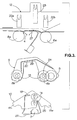
Figure 3 is an exploded view of the apparatus ofFigure 1 showing three constituent parts; -
Figures 4 to 9 are a sequence of illustrations showing the operation of the apparatus ofFigure 1 . -
Figure 1 shows the scanner carrier apparatus indicated generally at 1, in cross-section. Adocument 2 enters the apparatus 1 from the right-hand side and travels from right to left along a document path as indicated generally betweenarrows upper scanner 3 and alower scanner 4 which read optical marks or indices on respective sides of thedocument 2. - A first, lead,
roller 5 contacts thedocument 2 initially at the input to the apparatus and moves it further into the apparatus to engage with a second set ofrollers 6. The second roller set 6 guides thedocument 2 into adocument channel 7 so that it passes thescanners rollers 8 which drives it out of the apparatus in the direction ofarrow 9B. - The apparatus 1 comprises three interconnected but relatively moveable parts which will be referred to as a
scanner head assembly 10, abogey assembly 11 and acarrier assembly 12. These three parts are shown more clearly in the exploded view ofFigure 3 , parts of which will also be referred to here. - The
head assembly 10 has a scanner mounting on its lower side to which ascanner 3 is fixed. It is in close proximity to two laterally spacedrotational bearings 13 in thebogey assembly 11. It is also attached to thecarrier assembly 12 by two vertically spacedbearings 14 which constrain thehead assembly 10 to vertical movement only. In this way thescanner 3 always has its lower scanning face held at the same angle to the document travelling through the apparatus, regardless of the height of the head assembly above the document path, and hence regardless of the thickness of thedocument 2. - Each of the
bearings 13 on thebogey assembly 11 is connected by aspring 15 to thecarrier assembly 12. Thehead assembly 10 is connected to thecarrier assembly 12 by aspring 16. Hence thebogey assembly 11 and thehead assembly 10, with thescanner 3, are biased in a downward direction (as shown in the figures) toward the face of thedocument 2. However thebearings 13 on thebogey assembly 11 do not contact thehead assembly 10 in the normal steady state condition because there is a clearance gap 21 (Figures 1 and2 ) betweensurfaces 24 ofbearings 13 andsurfaces 25 ofhead assembly 10. There is an equal sized clearance between anabutment plate 19 on thehead assembly 10 and a downward facingsurface 20 on thebogey assembly 11. - As the
document 2 travels along thedocument path 9A-9B it contacts each in turn of the threeroller sets bogey assembly 11 is lifted by a distance dependent on the thickness of thedocument 2, against the force of thesprings 15, and will rock aboutbearings 13 depending on where the document is in the path and its thickness. If thedocument 2 is thicker than theclearance gap 21 then theupper surfaces 24 on thebearings 13 contact thelower surfaces 25 onarms head assembly 10. Inaddition abutment plate 19contacts surface 20. - As the
bogey assembly 11 lifts, and/or rotates on one or both ofbearings 13, it also causes thehead assembly 10 to rise inbearings 14 against the force of thespring 16. However thehead assembly 10 is constrained by the linear arrangement ofbearings 14 to substantially vertical translational movement. Hence the scanning face of thescanner 3 is kept parallel to the document to be read. -
Figure 2 shows the apparatus ofFigure 1 but thesprings document 2a in this example is much thinner than that inFigure 1 . Thisthin document 2a will not displace either thebogey assembly 11 or thehead assembly 10 becausebearings 13 do not contacthead assembly 10 atpoint 24/25 for thinner documents. It can be seen in this example that thedocument 2a does not contact theinput roller 5 because of the large clearance distance. - The
individual constituent assemblies Figure 3 and each will now be described in more detail. Thehead assembly 10 is shown at the bottom of the figure, thebogey assembly 11 in the middle and thecarrier assembly 12 at the top. Thelower scanner 4 is mounted to a chassis also housing thecarrier assembly 12. Thelower rollers rollers carrier assembly 12 whilst theupper rollers bogey assembly 11. - The
head assembly 10 is a generally triangular shape and comprises two laterally extendingarms small distance 21 from the upperconvex surfaces 24 of thebearings 13. Thisclearance distance 21 is set by abutment of the lower one ofbearings 14 sitting on the lower edge ofslot 23 on thecarrier assembly 12. - The
bogey assembly 11 is a generally inverted U shape forming anarch 29 withbearings 13 mounted toward the end of each arm coaxial with respectiveupper rollers first roller 5 is mounted upstream of thesecond roller 6b. Contactsurface 20 forabutment plate 19 is on the upper side of thearch 29. - The
carriage assembly 12 sits within a chassis, which comprises the correspondinglower rollers lower surface scanner 4. Thecarriage assembly 12 comprises spring mounts 22a, 22b and 23.Mounts springs 15 which act on thebearings 13, and mount 23 is adapted to hold thespring 16 which acts on theupper bearing 14. -
Figures 4 to 9 illustrate a sequence in the operation of the apparatus 1 ofFigure 1 . - In
Figure 4 theincoming document 2 is in contact with thefirst roller 5. Theroller 5 is part of themoveable bogey assembly 11.Contact point 24 onbogey assembly 11 makes contact withhead assembly 10 atcontact point 25. In this example a relativelythick document 2 is being used and this causes theroller 5 to lift. This lifts the right-hand side of thebogey assembly 11 rotating it about the left-hand bearing 13. In turn this moves thehead assembly 10 upwards. However thescanner head 3 maintains a parallel face to the upper surface ofdocument 2 because ofvertical bearings 14. - In
Figure 5 thedocument 2 progresses towards thescanner head 3 and contacts the second set ofrollers 6. Due to the thickness of thedocument 2 thebogey assembly 11 rotates further in an anti-clockwise direction and thehead assembly 10 is pushed further upwards through contact betweenpoint 24 on thebogey assembly head assembly 10, as well as contact betweenpoints 19 on thehead assembly bogey assembly 11. - In
Figure 6 thedocument 2 is fully engaged by therollers 6 and thehead assembly 10 has moved automatically upwards into the appropriate position for thescanner head 3 to read thedocument 2. - In
Figure 7 thedocument 2 has progressed through the apparatus and its leading edge is now betweenrollers 8. This rotates thebogey assembly 11 in a clockwise direction andbogey assembly 11 andhead assembly 10 are now in their uppermost reading position. - In
Figure 8 thedocument 2 starts to clear thescanner head 3 which allowsroller 6 to begin moving down to return to its lower start position. Theroller 8 is still held higher via contact betweenpoints - In
Figure 9 thedocument 2 is now clear of thescanner head 3 andexit rollers 8 and thebogey assembly 11 has moved back down to its starting position and is now free to start the sequence again. - The
input roller 5 is set to provide a predetermined clearance gap (typically 2.5mm) between its outer circumference and the input platform but therollers document 2 to be read is thin, as shown inFigure 2 , it will pass under theinput roller 5 and thebogey assembly 11 will not move upwardly until the document reaches the second set ofrollers 6. A clearance distance of typically 1mm is provided between the contact points 24 and 25 and betweensurfaces document 2 is less than 1mm thick thebogey assembly 11 will move upwardly but will not contact the head assembly and will not move the head assembly upwards. For such thin documentsresilient guide tapes scanner head 3 contacts thedocument 2. Theguide tape 27 for theupper scanner head 3 is mounted on the chassis which also houses thecarrier assembly 12, and theguide tape 28 for thelower scanner head 4 forms part of thehead assembly 10. When thedocument 2 makes contact with one of theguide tapes document 2 to be deflected towards and make contact with therespective scanner head guide tapes - Hence the
guide tapes document 2 contact the scanner heads 3 and 4 whereas the floating nature of the head andbogey assemblies upper scanner head 3 parallel to thedocument 2. - This arrangement has been found to work well with a wide variety of documents of various thicknesses, and acts to keep the document in contact with the scanner heads, yet retains the necessary parallel orientation of the scanner heads with respect to the surface of the document being scanned.
Claims (10)
- Apparatus for supporting a scanner head, the apparatus comprising:a carrier assembly (12);a bogey assembly (11); anda scanner head assembly (10), comprising a mounting for holding a scanner head;wherein the scanner head assembly (10) and the bogey assembly (11) are both mounted on spring bearings on the carrier assembly (12) such that they can both move in a vertical direction, andthe scanner head assembly (10) comprises at least two collinear vertical bearings (14) which restrict movement of the scanner head assembly (10) to vertical movement substantially perpendicular to a document path, andthe bogey assembly (11) comprises two laterally spaced bearings (13) which allow rotational movement of the bogey assembly (11) about the scanner head mounting (3).
- Apparatus according to claim 1 wherein the laterally spaced bearings (13) are housed within cut-outs (22a, 22b) on the carrier assembly (12) and the two laterally spaced bearing points are disposed on opposite sides of the scanner head along the document path.
- Apparatus according to claim 1 or claim 2 wherein the bogey assembly comprises at least two sets of rollers laterally spaced on opposite sides of the scanner head along the document path.
- Apparatus according to claim 3 wherein the bogey assembly comprises a lead roller at the input side of the document path which is positioned to provide a predetermined clearance from an input conveyor.
- Apparatus according to any one of the preceding claims wherein the carrier assembly comprises a spring housing for a spring which provides a bias between the carrier assembly and the scanner head assembly toward the document path.
- Apparatus according to any one of the preceding claims wherein the carrier assembly comprises a spring housing for a spring which provides a bias between the carrier assembly and the bogey assembly on each side of the scanner head.
- Apparatus according to any one of claims 3 to 6 comprising an upper abutment between the scanner head assembly and the bogey assembly, vertically spaced from the first contact points.
- Apparatus according to any one of the preceding claims further comprising a second scanner head positioned below the document path.
- Apparatus according to any one of the preceding claims further comprising at least one resilient flat guide spring positioned so as to deflect a document travelling along the document path to contact the scanning face of the scanning head.
- Apparatus according to claim 9 further comprising a second resilient flat guide spring, positioned so as to deflect a document travelling along the document path into contact with a second scanning head located below the document path.
Applications Claiming Priority (1)
| Application Number | Priority Date | Filing Date | Title |
|---|---|---|---|
| GB0909931A GB2470925A (en) | 2009-06-09 | 2009-06-09 | Automatically Adjusting Scanner Carrier Apparatus |
Publications (3)
| Publication Number | Publication Date |
|---|---|
| EP2261838A2 true EP2261838A2 (en) | 2010-12-15 |
| EP2261838A3 EP2261838A3 (en) | 2016-08-17 |
| EP2261838B1 EP2261838B1 (en) | 2017-12-13 |
Family
ID=40937142
Family Applications (1)
| Application Number | Title | Priority Date | Filing Date |
|---|---|---|---|
| EP10165440.8A Active EP2261838B1 (en) | 2009-06-09 | 2010-06-09 | Scanner carrier apparatus |
Country Status (3)
| Country | Link |
|---|---|
| US (1) | US8462397B2 (en) |
| EP (1) | EP2261838B1 (en) |
| GB (1) | GB2470925A (en) |
Families Citing this family (1)
| Publication number | Priority date | Publication date | Assignee | Title |
|---|---|---|---|---|
| JP7707809B2 (en) * | 2021-09-30 | 2025-07-15 | セイコーエプソン株式会社 | Image reader |
Citations (1)
| Publication number | Priority date | Publication date | Assignee | Title |
|---|---|---|---|---|
| US5171980A (en) | 1991-08-01 | 1992-12-15 | Pitney Bowes Inc. | Self adjusting scanner apparatus maintaining scan distance |
Family Cites Families (12)
| Publication number | Priority date | Publication date | Assignee | Title |
|---|---|---|---|---|
| US4764815A (en) * | 1985-06-24 | 1988-08-16 | Powers Chemco | Array scanning system with movable platen |
| AU7586187A (en) * | 1986-10-06 | 1988-04-21 | Stefan Grigore De Fay | Method and portable device for acquiring, storing and optionally processing and reproducing graphic signs from any medium |
| IT1257545B (en) * | 1992-06-15 | 1996-01-30 | Olivetti & Co Spa | FACSIMILE EQUIPMENT WITH INK JET PRINTER. |
| GB2282476A (en) * | 1993-09-30 | 1995-04-05 | Mars Inc | Document handling systems |
| US5578813A (en) * | 1995-03-02 | 1996-11-26 | Allen; Ross R. | Freehand image scanning device which compensates for non-linear movement |
| JPH09284471A (en) * | 1996-04-18 | 1997-10-31 | Canon Inc | Scanner head cartridge, method of using the same, and information processing apparatus using the scanner head cartridge |
| US6167232A (en) * | 1998-03-12 | 2000-12-26 | Hewlett-Packard Company | Automatic document feeder for a flat bed input device and background plate for use with same |
| JP3576879B2 (en) * | 1999-09-06 | 2004-10-13 | キヤノン株式会社 | Printing equipment |
| US6471202B1 (en) * | 1999-10-29 | 2002-10-29 | Canon Kabushiki Kaisha | Sheet feeding apparatus and image processing apparatus |
| JP3667193B2 (en) * | 2000-04-12 | 2005-07-06 | キヤノン株式会社 | Scanner head and image processing apparatus |
| US8040575B2 (en) * | 2005-05-14 | 2011-10-18 | Wisecube Co., Ltd. | Double side image scanner |
| FR2926180A1 (en) * | 2008-01-04 | 2009-07-10 | Neopost Technologies Sa | INTEGRATED IMAGE SENSOR POSTAGE SYSTEM. |
-
2009
- 2009-06-09 GB GB0909931A patent/GB2470925A/en not_active Withdrawn
-
2010
- 2010-06-07 US US12/795,094 patent/US8462397B2/en active Active
- 2010-06-09 EP EP10165440.8A patent/EP2261838B1/en active Active
Patent Citations (1)
| Publication number | Priority date | Publication date | Assignee | Title |
|---|---|---|---|---|
| US5171980A (en) | 1991-08-01 | 1992-12-15 | Pitney Bowes Inc. | Self adjusting scanner apparatus maintaining scan distance |
Also Published As
| Publication number | Publication date |
|---|---|
| EP2261838A3 (en) | 2016-08-17 |
| EP2261838B1 (en) | 2017-12-13 |
| US20100309531A1 (en) | 2010-12-09 |
| US8462397B2 (en) | 2013-06-11 |
| GB0909931D0 (en) | 2009-07-22 |
| GB2470925A (en) | 2010-12-15 |
Similar Documents
| Publication | Publication Date | Title |
|---|---|---|
| US4764976A (en) | Document reader module | |
| US8223406B2 (en) | Image reading apparatus | |
| JP5440160B2 (en) | Loading device, conveying device, and recording device | |
| EP0063600B1 (en) | Plotter having a concave platen | |
| EP1457445B1 (en) | Sheet feeder in image reading apparatus | |
| JP4468108B2 (en) | Image reading device | |
| US8177221B2 (en) | Sheet separation device, sheet feed tray including the sheet separation device, and sheet feed apparatus including the sheet separation device | |
| US6824131B2 (en) | Method and apparatus for image forming and effectively performing sheet feeding using a sheet feed roller and a tilt member | |
| EP2261838B1 (en) | Scanner carrier apparatus | |
| US5171980A (en) | Self adjusting scanner apparatus maintaining scan distance | |
| KR100896023B1 (en) | printer | |
| EP0707974A3 (en) | Scanning unit with independent spring-loaded document control components mounted on an integrated chassis | |
| US9630793B2 (en) | Sheet conveying device | |
| JP2001058751A (en) | Sheet discharge mechanism of printing device | |
| EP0180778B1 (en) | Floating document throat | |
| KR20060048483A (en) | Image processing unit | |
| US20060252590A1 (en) | Detachable feed tray with self adjusting side guides | |
| JP2007145572A (en) | Paper sheet separating-delivering mechanism | |
| JP4112288B2 (en) | Double-sided image reader | |
| JP2002152463A (en) | Automatic document feeder and image reading device | |
| JPH04369162A (en) | Original reader | |
| US11964841B2 (en) | Feeding apparatus and printing apparatus | |
| JPH0318546A (en) | Automatic document feeder and ejector | |
| JP4472483B2 (en) | Image reading device | |
| JP2007062961A (en) | Sheet feeding apparatus and image forming apparatus |
Legal Events
| Date | Code | Title | Description |
|---|---|---|---|
| PUAI | Public reference made under article 153(3) epc to a published international application that has entered the european phase |
Free format text: ORIGINAL CODE: 0009012 |
|
| AK | Designated contracting states |
Kind code of ref document: A2 Designated state(s): AL AT BE BG CH CY CZ DE DK EE ES FI FR GB GR HR HU IE IS IT LI LT LU LV MC MK MT NL NO PL PT RO SE SI SK SM TR |
|
| AX | Request for extension of the european patent |
Extension state: BA ME RS |
|
| PUAL | Search report despatched |
Free format text: ORIGINAL CODE: 0009013 |
|
| AK | Designated contracting states |
Kind code of ref document: A3 Designated state(s): AL AT BE BG CH CY CZ DE DK EE ES FI FR GB GR HR HU IE IS IT LI LT LU LV MC MK MT NL NO PL PT RO SE SI SK SM TR |
|
| AX | Request for extension of the european patent |
Extension state: BA ME RS |
|
| RIC1 | Information provided on ipc code assigned before grant |
Ipc: H04N 1/203 20060101ALI20160714BHEP Ipc: H04N 1/00 20060101ALI20160714BHEP Ipc: G06K 7/10 20060101AFI20160714BHEP Ipc: H04N 1/12 20060101ALI20160714BHEP Ipc: B07C 3/14 20060101ALI20160714BHEP |
|
| 17P | Request for examination filed |
Effective date: 20170130 |
|
| RBV | Designated contracting states (corrected) |
Designated state(s): AL AT BE BG CH CY CZ DE DK EE ES FI FR GB GR HR HU IE IS IT LI LT LU LV MC MK MT NL NO PL PT RO SE SI SK SM TR |
|
| GRAP | Despatch of communication of intention to grant a patent |
Free format text: ORIGINAL CODE: EPIDOSNIGR1 |
|
| INTG | Intention to grant announced |
Effective date: 20170718 |
|
| GRAS | Grant fee paid |
Free format text: ORIGINAL CODE: EPIDOSNIGR3 |
|
| GRAA | (expected) grant |
Free format text: ORIGINAL CODE: 0009210 |
|
| AK | Designated contracting states |
Kind code of ref document: B1 Designated state(s): AL AT BE BG CH CY CZ DE DK EE ES FI FR GB GR HR HU IE IS IT LI LT LU LV MC MK MT NL NO PL PT RO SE SI SK SM TR |
|
| REG | Reference to a national code |
Ref country code: GB Ref legal event code: FG4D |
|
| REG | Reference to a national code |
Ref country code: AT Ref legal event code: REF Ref document number: 955054 Country of ref document: AT Kind code of ref document: T Effective date: 20171215 Ref country code: CH Ref legal event code: EP |
|
| REG | Reference to a national code |
Ref country code: IE Ref legal event code: FG4D |
|
| REG | Reference to a national code |
Ref country code: DE Ref legal event code: R096 Ref document number: 602010047302 Country of ref document: DE |
|
| REG | Reference to a national code |
Ref country code: NL Ref legal event code: MP Effective date: 20171213 |
|
| REG | Reference to a national code |
Ref country code: LT Ref legal event code: MG4D |
|
| PG25 | Lapsed in a contracting state [announced via postgrant information from national office to epo] |
Ref country code: SE Free format text: LAPSE BECAUSE OF FAILURE TO SUBMIT A TRANSLATION OF THE DESCRIPTION OR TO PAY THE FEE WITHIN THE PRESCRIBED TIME-LIMIT Effective date: 20171213 Ref country code: FI Free format text: LAPSE BECAUSE OF FAILURE TO SUBMIT A TRANSLATION OF THE DESCRIPTION OR TO PAY THE FEE WITHIN THE PRESCRIBED TIME-LIMIT Effective date: 20171213 Ref country code: NO Free format text: LAPSE BECAUSE OF FAILURE TO SUBMIT A TRANSLATION OF THE DESCRIPTION OR TO PAY THE FEE WITHIN THE PRESCRIBED TIME-LIMIT Effective date: 20180313 Ref country code: LT Free format text: LAPSE BECAUSE OF FAILURE TO SUBMIT A TRANSLATION OF THE DESCRIPTION OR TO PAY THE FEE WITHIN THE PRESCRIBED TIME-LIMIT Effective date: 20171213 |
|
| REG | Reference to a national code |
Ref country code: AT Ref legal event code: MK05 Ref document number: 955054 Country of ref document: AT Kind code of ref document: T Effective date: 20171213 |
|
| PG25 | Lapsed in a contracting state [announced via postgrant information from national office to epo] |
Ref country code: HR Free format text: LAPSE BECAUSE OF FAILURE TO SUBMIT A TRANSLATION OF THE DESCRIPTION OR TO PAY THE FEE WITHIN THE PRESCRIBED TIME-LIMIT Effective date: 20171213 Ref country code: LV Free format text: LAPSE BECAUSE OF FAILURE TO SUBMIT A TRANSLATION OF THE DESCRIPTION OR TO PAY THE FEE WITHIN THE PRESCRIBED TIME-LIMIT Effective date: 20171213 Ref country code: BG Free format text: LAPSE BECAUSE OF FAILURE TO SUBMIT A TRANSLATION OF THE DESCRIPTION OR TO PAY THE FEE WITHIN THE PRESCRIBED TIME-LIMIT Effective date: 20180313 Ref country code: GR Free format text: LAPSE BECAUSE OF FAILURE TO SUBMIT A TRANSLATION OF THE DESCRIPTION OR TO PAY THE FEE WITHIN THE PRESCRIBED TIME-LIMIT Effective date: 20180314 |
|
| REG | Reference to a national code |
Ref country code: FR Ref legal event code: PLFP Year of fee payment: 9 |
|
| PG25 | Lapsed in a contracting state [announced via postgrant information from national office to epo] |
Ref country code: NL Free format text: LAPSE BECAUSE OF FAILURE TO SUBMIT A TRANSLATION OF THE DESCRIPTION OR TO PAY THE FEE WITHIN THE PRESCRIBED TIME-LIMIT Effective date: 20171213 |
|
| PG25 | Lapsed in a contracting state [announced via postgrant information from national office to epo] |
Ref country code: SK Free format text: LAPSE BECAUSE OF FAILURE TO SUBMIT A TRANSLATION OF THE DESCRIPTION OR TO PAY THE FEE WITHIN THE PRESCRIBED TIME-LIMIT Effective date: 20171213 Ref country code: EE Free format text: LAPSE BECAUSE OF FAILURE TO SUBMIT A TRANSLATION OF THE DESCRIPTION OR TO PAY THE FEE WITHIN THE PRESCRIBED TIME-LIMIT Effective date: 20171213 Ref country code: CY Free format text: LAPSE BECAUSE OF FAILURE TO SUBMIT A TRANSLATION OF THE DESCRIPTION OR TO PAY THE FEE WITHIN THE PRESCRIBED TIME-LIMIT Effective date: 20171213 Ref country code: CZ Free format text: LAPSE BECAUSE OF FAILURE TO SUBMIT A TRANSLATION OF THE DESCRIPTION OR TO PAY THE FEE WITHIN THE PRESCRIBED TIME-LIMIT Effective date: 20171213 Ref country code: ES Free format text: LAPSE BECAUSE OF FAILURE TO SUBMIT A TRANSLATION OF THE DESCRIPTION OR TO PAY THE FEE WITHIN THE PRESCRIBED TIME-LIMIT Effective date: 20171213 |
|
| PG25 | Lapsed in a contracting state [announced via postgrant information from national office to epo] |
Ref country code: IT Free format text: LAPSE BECAUSE OF FAILURE TO SUBMIT A TRANSLATION OF THE DESCRIPTION OR TO PAY THE FEE WITHIN THE PRESCRIBED TIME-LIMIT Effective date: 20171213 Ref country code: PL Free format text: LAPSE BECAUSE OF FAILURE TO SUBMIT A TRANSLATION OF THE DESCRIPTION OR TO PAY THE FEE WITHIN THE PRESCRIBED TIME-LIMIT Effective date: 20171213 Ref country code: SM Free format text: LAPSE BECAUSE OF FAILURE TO SUBMIT A TRANSLATION OF THE DESCRIPTION OR TO PAY THE FEE WITHIN THE PRESCRIBED TIME-LIMIT Effective date: 20171213 Ref country code: AT Free format text: LAPSE BECAUSE OF FAILURE TO SUBMIT A TRANSLATION OF THE DESCRIPTION OR TO PAY THE FEE WITHIN THE PRESCRIBED TIME-LIMIT Effective date: 20171213 Ref country code: IS Free format text: LAPSE BECAUSE OF FAILURE TO SUBMIT A TRANSLATION OF THE DESCRIPTION OR TO PAY THE FEE WITHIN THE PRESCRIBED TIME-LIMIT Effective date: 20180413 Ref country code: RO Free format text: LAPSE BECAUSE OF FAILURE TO SUBMIT A TRANSLATION OF THE DESCRIPTION OR TO PAY THE FEE WITHIN THE PRESCRIBED TIME-LIMIT Effective date: 20171213 |
|
| REG | Reference to a national code |
Ref country code: DE Ref legal event code: R097 Ref document number: 602010047302 Country of ref document: DE |
|
| PLBE | No opposition filed within time limit |
Free format text: ORIGINAL CODE: 0009261 |
|
| STAA | Information on the status of an ep patent application or granted ep patent |
Free format text: STATUS: NO OPPOSITION FILED WITHIN TIME LIMIT |
|
| 26N | No opposition filed |
Effective date: 20180914 |
|
| PG25 | Lapsed in a contracting state [announced via postgrant information from national office to epo] |
Ref country code: DK Free format text: LAPSE BECAUSE OF FAILURE TO SUBMIT A TRANSLATION OF THE DESCRIPTION OR TO PAY THE FEE WITHIN THE PRESCRIBED TIME-LIMIT Effective date: 20171213 |
|
| REG | Reference to a national code |
Ref country code: CH Ref legal event code: PL |
|
| PG25 | Lapsed in a contracting state [announced via postgrant information from national office to epo] |
Ref country code: SI Free format text: LAPSE BECAUSE OF FAILURE TO SUBMIT A TRANSLATION OF THE DESCRIPTION OR TO PAY THE FEE WITHIN THE PRESCRIBED TIME-LIMIT Effective date: 20171213 |
|
| REG | Reference to a national code |
Ref country code: BE Ref legal event code: MM Effective date: 20180630 |
|
| REG | Reference to a national code |
Ref country code: IE Ref legal event code: MM4A |
|
| PG25 | Lapsed in a contracting state [announced via postgrant information from national office to epo] |
Ref country code: LU Free format text: LAPSE BECAUSE OF NON-PAYMENT OF DUE FEES Effective date: 20180609 Ref country code: MC Free format text: LAPSE BECAUSE OF FAILURE TO SUBMIT A TRANSLATION OF THE DESCRIPTION OR TO PAY THE FEE WITHIN THE PRESCRIBED TIME-LIMIT Effective date: 20171213 |
|
| PG25 | Lapsed in a contracting state [announced via postgrant information from national office to epo] |
Ref country code: IE Free format text: LAPSE BECAUSE OF NON-PAYMENT OF DUE FEES Effective date: 20180609 Ref country code: CH Free format text: LAPSE BECAUSE OF NON-PAYMENT OF DUE FEES Effective date: 20180630 Ref country code: LI Free format text: LAPSE BECAUSE OF NON-PAYMENT OF DUE FEES Effective date: 20180630 |
|
| PG25 | Lapsed in a contracting state [announced via postgrant information from national office to epo] |
Ref country code: BE Free format text: LAPSE BECAUSE OF NON-PAYMENT OF DUE FEES Effective date: 20180630 |
|
| PG25 | Lapsed in a contracting state [announced via postgrant information from national office to epo] |
Ref country code: MT Free format text: LAPSE BECAUSE OF NON-PAYMENT OF DUE FEES Effective date: 20180609 |
|
| PG25 | Lapsed in a contracting state [announced via postgrant information from national office to epo] |
Ref country code: TR Free format text: LAPSE BECAUSE OF FAILURE TO SUBMIT A TRANSLATION OF THE DESCRIPTION OR TO PAY THE FEE WITHIN THE PRESCRIBED TIME-LIMIT Effective date: 20171213 |
|
| PG25 | Lapsed in a contracting state [announced via postgrant information from national office to epo] |
Ref country code: PT Free format text: LAPSE BECAUSE OF FAILURE TO SUBMIT A TRANSLATION OF THE DESCRIPTION OR TO PAY THE FEE WITHIN THE PRESCRIBED TIME-LIMIT Effective date: 20171213 Ref country code: HU Free format text: LAPSE BECAUSE OF FAILURE TO SUBMIT A TRANSLATION OF THE DESCRIPTION OR TO PAY THE FEE WITHIN THE PRESCRIBED TIME-LIMIT; INVALID AB INITIO Effective date: 20100609 |
|
| PG25 | Lapsed in a contracting state [announced via postgrant information from national office to epo] |
Ref country code: MK Free format text: LAPSE BECAUSE OF NON-PAYMENT OF DUE FEES Effective date: 20171213 |
|
| PG25 | Lapsed in a contracting state [announced via postgrant information from national office to epo] |
Ref country code: AL Free format text: LAPSE BECAUSE OF FAILURE TO SUBMIT A TRANSLATION OF THE DESCRIPTION OR TO PAY THE FEE WITHIN THE PRESCRIBED TIME-LIMIT Effective date: 20171213 |
|
| REG | Reference to a national code |
Ref country code: DE Ref legal event code: R082 Ref document number: 602010047302 Country of ref document: DE Representative=s name: CBDL PATENTANWAELTE GBR, DE Ref country code: DE Ref legal event code: R082 Ref document number: 602010047302 Country of ref document: DE Representative=s name: CBDL PATENTANWAELTE EGBR, DE |
|
| PGFP | Annual fee paid to national office [announced via postgrant information from national office to epo] |
Ref country code: DE Payment date: 20250618 Year of fee payment: 16 |
|
| PGFP | Annual fee paid to national office [announced via postgrant information from national office to epo] |
Ref country code: GB Payment date: 20250618 Year of fee payment: 16 |
|
| PGFP | Annual fee paid to national office [announced via postgrant information from national office to epo] |
Ref country code: FR Payment date: 20250624 Year of fee payment: 16 |