EP2261690A2 - Image sensor for measuring illumination, proximity and color temperature - Google Patents
Image sensor for measuring illumination, proximity and color temperature Download PDFInfo
- Publication number
- EP2261690A2 EP2261690A2 EP10164770A EP10164770A EP2261690A2 EP 2261690 A2 EP2261690 A2 EP 2261690A2 EP 10164770 A EP10164770 A EP 10164770A EP 10164770 A EP10164770 A EP 10164770A EP 2261690 A2 EP2261690 A2 EP 2261690A2
- Authority
- EP
- European Patent Office
- Prior art keywords
- infrared
- light source
- proximity
- image sensor
- wavelength
- Prior art date
- Legal status (The legal status is an assumption and is not a legal conclusion. Google has not performed a legal analysis and makes no representation as to the accuracy of the status listed.)
- Granted
Links
Images


Classifications
-
- G—PHYSICS
- G01—MEASURING; TESTING
- G01S—RADIO DIRECTION-FINDING; RADIO NAVIGATION; DETERMINING DISTANCE OR VELOCITY BY USE OF RADIO WAVES; LOCATING OR PRESENCE-DETECTING BY USE OF THE REFLECTION OR RERADIATION OF RADIO WAVES; ANALOGOUS ARRANGEMENTS USING OTHER WAVES
- G01S17/00—Systems using the reflection or reradiation of electromagnetic waves other than radio waves, e.g. lidar systems
- G01S17/88—Lidar systems specially adapted for specific applications
- G01S17/89—Lidar systems specially adapted for specific applications for mapping or imaging
-
- H—ELECTRICITY
- H10—SEMICONDUCTOR DEVICES; ELECTRIC SOLID-STATE DEVICES NOT OTHERWISE PROVIDED FOR
- H10F—INORGANIC SEMICONDUCTOR DEVICES SENSITIVE TO INFRARED RADIATION, LIGHT, ELECTROMAGNETIC RADIATION OF SHORTER WAVELENGTH OR CORPUSCULAR RADIATION
- H10F39/00—Integrated devices, or assemblies of multiple devices, comprising at least one element covered by group H10F30/00, e.g. radiation detectors comprising photodiode arrays
- H10F39/10—Integrated devices
- H10F39/12—Image sensors
-
- G—PHYSICS
- G01—MEASURING; TESTING
- G01J—MEASUREMENT OF INTENSITY, VELOCITY, SPECTRAL CONTENT, POLARISATION, PHASE OR PULSE CHARACTERISTICS OF INFRARED, VISIBLE OR ULTRAVIOLET LIGHT; COLORIMETRY; RADIATION PYROMETRY
- G01J3/00—Spectrometry; Spectrophotometry; Monochromators; Measuring colours
- G01J3/02—Details
-
- G—PHYSICS
- G01—MEASURING; TESTING
- G01J—MEASUREMENT OF INTENSITY, VELOCITY, SPECTRAL CONTENT, POLARISATION, PHASE OR PULSE CHARACTERISTICS OF INFRARED, VISIBLE OR ULTRAVIOLET LIGHT; COLORIMETRY; RADIATION PYROMETRY
- G01J3/00—Spectrometry; Spectrophotometry; Monochromators; Measuring colours
- G01J3/02—Details
- G01J3/0205—Optical elements not provided otherwise, e.g. optical manifolds, diffusers, windows
- G01J3/0208—Optical elements not provided otherwise, e.g. optical manifolds, diffusers, windows using focussing or collimating elements, e.g. lenses or mirrors; performing aberration correction
-
- G—PHYSICS
- G01—MEASURING; TESTING
- G01J—MEASUREMENT OF INTENSITY, VELOCITY, SPECTRAL CONTENT, POLARISATION, PHASE OR PULSE CHARACTERISTICS OF INFRARED, VISIBLE OR ULTRAVIOLET LIGHT; COLORIMETRY; RADIATION PYROMETRY
- G01J3/00—Spectrometry; Spectrophotometry; Monochromators; Measuring colours
- G01J3/02—Details
- G01J3/027—Control of working procedures of a spectrometer; Failure detection; Bandwidth calculation
-
- G—PHYSICS
- G01—MEASURING; TESTING
- G01J—MEASUREMENT OF INTENSITY, VELOCITY, SPECTRAL CONTENT, POLARISATION, PHASE OR PULSE CHARACTERISTICS OF INFRARED, VISIBLE OR ULTRAVIOLET LIGHT; COLORIMETRY; RADIATION PYROMETRY
- G01J3/00—Spectrometry; Spectrophotometry; Monochromators; Measuring colours
- G01J3/02—Details
- G01J3/0278—Control or determination of height or angle information for sensors or receivers
-
- G—PHYSICS
- G01—MEASURING; TESTING
- G01J—MEASUREMENT OF INTENSITY, VELOCITY, SPECTRAL CONTENT, POLARISATION, PHASE OR PULSE CHARACTERISTICS OF INFRARED, VISIBLE OR ULTRAVIOLET LIGHT; COLORIMETRY; RADIATION PYROMETRY
- G01J3/00—Spectrometry; Spectrophotometry; Monochromators; Measuring colours
- G01J3/46—Measurement of colour; Colour measuring devices, e.g. colorimeters
- G01J3/50—Measurement of colour; Colour measuring devices, e.g. colorimeters using electric radiation detectors
- G01J3/51—Measurement of colour; Colour measuring devices, e.g. colorimeters using electric radiation detectors using colour filters
-
- G—PHYSICS
- G01—MEASURING; TESTING
- G01J—MEASUREMENT OF INTENSITY, VELOCITY, SPECTRAL CONTENT, POLARISATION, PHASE OR PULSE CHARACTERISTICS OF INFRARED, VISIBLE OR ULTRAVIOLET LIGHT; COLORIMETRY; RADIATION PYROMETRY
- G01J3/00—Spectrometry; Spectrophotometry; Monochromators; Measuring colours
- G01J3/46—Measurement of colour; Colour measuring devices, e.g. colorimeters
- G01J3/50—Measurement of colour; Colour measuring devices, e.g. colorimeters using electric radiation detectors
- G01J3/51—Measurement of colour; Colour measuring devices, e.g. colorimeters using electric radiation detectors using colour filters
- G01J3/513—Measurement of colour; Colour measuring devices, e.g. colorimeters using electric radiation detectors using colour filters having fixed filter-detector pairs
-
- G—PHYSICS
- G01—MEASURING; TESTING
- G01S—RADIO DIRECTION-FINDING; RADIO NAVIGATION; DETERMINING DISTANCE OR VELOCITY BY USE OF RADIO WAVES; LOCATING OR PRESENCE-DETECTING BY USE OF THE REFLECTION OR RERADIATION OF RADIO WAVES; ANALOGOUS ARRANGEMENTS USING OTHER WAVES
- G01S17/00—Systems using the reflection or reradiation of electromagnetic waves other than radio waves, e.g. lidar systems
- G01S17/87—Combinations of systems using electromagnetic waves other than radio waves
-
- G—PHYSICS
- G01—MEASURING; TESTING
- G01S—RADIO DIRECTION-FINDING; RADIO NAVIGATION; DETERMINING DISTANCE OR VELOCITY BY USE OF RADIO WAVES; LOCATING OR PRESENCE-DETECTING BY USE OF THE REFLECTION OR RERADIATION OF RADIO WAVES; ANALOGOUS ARRANGEMENTS USING OTHER WAVES
- G01S7/00—Details of systems according to groups G01S13/00, G01S15/00, G01S17/00
- G01S7/48—Details of systems according to groups G01S13/00, G01S15/00, G01S17/00 of systems according to group G01S17/00
- G01S7/481—Constructional features, e.g. arrangements of optical elements
- G01S7/4816—Constructional features, e.g. arrangements of optical elements of receivers alone
-
- G—PHYSICS
- G01—MEASURING; TESTING
- G01S—RADIO DIRECTION-FINDING; RADIO NAVIGATION; DETERMINING DISTANCE OR VELOCITY BY USE OF RADIO WAVES; LOCATING OR PRESENCE-DETECTING BY USE OF THE REFLECTION OR RERADIATION OF RADIO WAVES; ANALOGOUS ARRANGEMENTS USING OTHER WAVES
- G01S7/00—Details of systems according to groups G01S13/00, G01S15/00, G01S17/00
- G01S7/48—Details of systems according to groups G01S13/00, G01S15/00, G01S17/00 of systems according to group G01S17/00
- G01S7/491—Details of non-pulse systems
-
- H—ELECTRICITY
- H04—ELECTRIC COMMUNICATION TECHNIQUE
- H04N—PICTORIAL COMMUNICATION, e.g. TELEVISION
- H04N23/00—Cameras or camera modules comprising electronic image sensors; Control thereof
- H04N23/10—Cameras or camera modules comprising electronic image sensors; Control thereof for generating image signals from different wavelengths
- H04N23/11—Cameras or camera modules comprising electronic image sensors; Control thereof for generating image signals from different wavelengths for generating image signals from visible and infrared light wavelengths
-
- H—ELECTRICITY
- H04—ELECTRIC COMMUNICATION TECHNIQUE
- H04N—PICTORIAL COMMUNICATION, e.g. TELEVISION
- H04N23/00—Cameras or camera modules comprising electronic image sensors; Control thereof
- H04N23/56—Cameras or camera modules comprising electronic image sensors; Control thereof provided with illuminating means
-
- H—ELECTRICITY
- H04—ELECTRIC COMMUNICATION TECHNIQUE
- H04N—PICTORIAL COMMUNICATION, e.g. TELEVISION
- H04N25/00—Circuitry of solid-state image sensors [SSIS]; Control thereof
- H04N25/70—SSIS architectures; Circuits associated therewith
- H04N25/703—SSIS architectures incorporating pixels for producing signals other than image signals
- H04N25/706—Pixels for exposure or ambient light measuring
-
- H—ELECTRICITY
- H04—ELECTRIC COMMUNICATION TECHNIQUE
- H04N—PICTORIAL COMMUNICATION, e.g. TELEVISION
- H04N23/00—Cameras or camera modules comprising electronic image sensors; Control thereof
- H04N23/20—Cameras or camera modules comprising electronic image sensors; Control thereof for generating image signals from infrared radiation only
Definitions
- the present invention relates to image sensing.
- An embodiment relates to an image sensor capable of measuring illumination, proximity and color temperature, which can measure current illumination, proximity to an object and color temperature of the object by using variation of an output voltage value according to the existence or absence of infrared and visible ray with a wavelength of a specific band.
- an image sensor using a charge-coupled device (CCD) or a complementary metal-oxide semiconductor (CMOS) has an absorption band of 40nm to 1100nm. Furthermore, visible ray normally has a wavelength of 380nm to 650nm and infrared has a wavelength of 650nm to 1100nm. It is general that such an image sensor uses an infrared (IR) cut-off filter, which allows light with a wavelength of 650nm or less to pass therethrough and cuts off light (i.e., infrared) with a wavelength of 650nm or more, in order to detect and display colors the same as those perceived by the human eye.
- IR infrared
- light in an infrared area is used as a light source in order to acquire an image by photographing an environment (e.g., a monitoring camera) with less external light, that is, a night environment, a sealed space after an electric light is turned off and the like, by using such an image sensor.
- an environment e.g., a monitoring camera
- the light in the infrared area is cut off by the IR cut-off filter to improve image quality.
- the IR cut-off filter is not used to allow the light in the infrared area to reach the image sensor.
- a moving unit capable of changing the position of the IR cut-off filter according to the existence or absence of the external light source is essentially required for a system using the image sensor. Installation of the moving unit that mechanically moves the IR cut-off filter may increase the size and manufacturing cost of a monitoring camera and the like.
- an infrared light emitting diode used for a conventional image sensor has been generally limited only to a function as a light source for acquiring an image in a dark environment.
- the proximity function capable of automatically controlling a mobile apparatus according to the distance between a user and the mobile apparatus in the case of using the mobile apparatus such as a digital camera or a cell phone, and an electronic apparatus.
- the proximity function has been proposed to reduce power consumption by automatically cutting off power supplied to a backlight unit (BLU) provided in a liquid crystal window, or to prevent an abnormal operation by automatically stopping the operation of a touch sensor.
- BLU backlight unit
- a proximity sensor separately manufactured using a light emitting diode (LED) and a light receiving element has been installed in a mobile apparatus, an electronic apparatus and the like for use.
- LED light emitting diode
- the separate proximity sensor when the separate proximity sensor is installed as described above, the size of the mobile apparatus, the electronic apparatus and the like is increased, resulting in going against the recent technology trend toward performance of a plurality of functions through miniaturization of products, and an increase in the manufacturing cost for installing the separate proximity sensor.
- an entire image pixel is required to measure the color sense or color temperature of an object, resulting in an increase in power consumption.
- An object of an embodiment is to provide an image sensor capable of measuring illumination, proximity and color temperature, which includes a separate second sensing unit having an illumination detector, a proximity detector and a color temperature detector provided in the vicinity of a first sensing unit having an image pixel in a system such as a camera provided with an image sensor, and can measure current illumination, proximity to an object and color temperature of the object based on variation of an output voltage value from the second sensing unit according to the existence or absence of infrared and visible ray with a wavelength of a specific band.
- an image sensor for measuring illumination, proximity and color temperature, including: a light source unit configured to irradiate infrared with a wavelength of a specific band onto an object; a light source controller configured to control power supplied to the light source unit; an infrared transmission filter configured to allow only the infrared and visible ray with the wavelength of the specific band among light incident through a lens after being reflected by the object to selectively transmit therethrough; a first sensing unit provided with an image pixel for acquiring an image of the object introduced through the infrared transmission filter; and a second sensing unit configured to receive the infrared and the visible ray having passed through the infrared transmission filter and measure current illumination, proximity to the object and color temperature of the object.
- the image sensor may include the separate second sensing unit provided in the vicinity of the first sensing unit having the image pixel while operating separately from the first sensing unit, thereby facilitating measurement of current illumination, proximity to an object and color temperature of the object while reducing power consumption.
- an image sensor 100 includes a light source unit 110, a light source controller 120, an infrared transmission filter 150, a first sensing unit 160 and a second sensing unit 170.
- the light source unit 110 irradiates infrared with a wavelength of a specific band onto an object 130.
- the light source unit 110 may include an infrared light emitting diode (LED) that irradiates infrared with a wavelength of 850nm onto the object 130.
- LED infrared light emitting diode
- the light source controller 120 includes an LED controller 121 that generates a control signal for controlling on/off of the light source unit 110, and an LED driver 122 that controls power supplied to the light source unit 110 based on the control signal.
- the infrared transmission filter 150 allows only infrared and visible ray with a wavelength of a specific band among light introduced through a lens 140 after being reflected by the object 130 to selectively transmit therethrough.
- the first sensing unit 160 includes an image pixel to acquire an image of the object 130 introduced through the infrared transmission filter 150.
- the second sensing unit 170 receives the infrared and visible ray with the wavelength of the specific band, which have passed through the infrared transmission filter 150, and measures current illumination, proximity to the object 130 and color temperature of the object 130.
- the second sensing unit 170 is separately provided in the vicinity of the first sensing unit 160 while independently operating without a connection to the image pixel of the first sensing unit 160.
- the second sensing unit 170 includes an illumination detector 171, a proximity detector 172 and a color temperature detector 173.
- the illumination detector 171 receives the infrared and visible ray with the wavelength of the specific band, which have passed through the infrared transmission filter 150, and measures the current illumination.
- the proximity detector 172 receives the infrared with the wavelength of the specific band, which has passed through the infrared transmission filter 150, and measures proximity to the object 130 based on a difference between output voltages according to the on/off of the light source unit 110.
- the color temperature detector 173 generates an output voltage based on the visible ray with the wavelength of the specific band, which has passed through the infrared transmission filter 150, and measures color temperature of the object 130.
- the illumination detector 171 may be provided in a plural number throughout the second sensing unit 170 in order to easily measure the brightness of light introduced from the exterior of the lens 140.
- the proximity detector 172 for determining the proximity to the object 130 and the color temperature detector 173 may also be provided in a plural number throughout the second sensing unit 170, similarly to the illumination detector 171.
- FIG. 3 shows the case in which a separate green pixel is used as the illumination detector 171.
- a green pixel provided in the color temperature detector 173, instead of the separate green pixel.
- the illumination detector 171 detects the brightness of the external light incident into the second sensing unit 170 after being reflected by the object 130 and passing through the lens 140.
- the illumination detector 171 is designed to have a spectrum the same as a brightness curve perceived by the human eye.
- the illumination detector 171 is provided in a plural number at an outside of the first sensing unit 160 including the image pixel while being adjacent thereto, so that an average of light reflected by the object 130 and thus the current illumination due to the external light can be relatively accurately measured from the average of the light.
- the proximity detector 172 includes an infrared (IR) pixel and further includes a blur (B) color filter and a red (R) color filter on the IR pixel. Furthermore, the proximity detector 172 generates output voltage values based on the infrared with the wavelength of the specific band, which is introduced into the lens 140 after being irradiated from the light source unit 140 and reflected by the object 130.
- IR infrared
- B blur
- R red
- the proximity detector 172 generates output voltage values based on the infrared with the wavelength of the specific band, which is introduced into the lens 140 after being irradiated from the light source unit 140 and reflected by the object 130.
- the blur (B) color filter and the red (R) color filter installed on the IR pixel of the proximity detector 172 serves as a visible ray cut-off filter that cuts off visible ray introduced after transmitting through the lens 140.
- the visible ray cut-off filter is provided on the infrared (IR) pixel of the proximity detector 172, so that the visible ray is prevented from reaching the proximity detector 172, and a difference between the output voltage values caused by only the infrared with the wavelength of the specific band, which is reflected by the object 130, is calculated, resulting in the improvement of the accuracy of proximity determination.
- the color temperature detector 173 includes a red (R) pixel, a green (G) pixel and a blue (B) pixel, detects an output voltage based on the visible ray with the wavelength of the specific band, which has passed through the infrared transmission filter 150, and measures the color temperature of the object 130. Furthermore, a red (R) color filter, a green (G) color filter and a blue (B) color filter may be provided on the red (R) pixel, the green (G) pixel and the blue (B) pixel, respectively.
- the red (R) pixel, the green (G) pixel and the blue (B) pixel are installed separately from an area in which the image pixel of the first sensing unit 160 is installed, and operate separately from the image pixel of the first sensing unit 160. Consequently, when measuring the color temperature of the object 130, R, G and B pixels provided in the color temperature detector 173 are used without directly using an image pixel causing high power consumption, so that the color temperature of the object 130 can be easily measured while reducing power consumption.
- the IR transmittance filter allows light with a wavelength of 400nm to 650nm (a visible ray area) in order to acquire an image, cuts off light in an infrared area which degrades color characteristics, and allows only infrared with a specific wavelength of 850nm band, which serves as a light source for determining the proximity of an object or a light source as an illumination for measuring the color temperature thereof, to transmit therethrough.
- the infrared LED can be utilized as a light source for the proximity determination and color temperature measurement of the object as well as a simple light source.
- V1 denotes an output voltage value measured by the proximity detector 172 based on the light introduced through the lens when the light source unit 110 irradiating infrared with the wavelength of 850nm band is turned on
- V2 denotes an output voltage value output from the proximity detector 172 when the light source unit 110 is turned off
- ⁇ Vd denotes the difference between V1 and V2.
- the intensity of the light incident into the proximity detector 172 after being reflected by the object 130 when the light source unit 110 is turned off is determined only by the intensity of external light.
- the intensity of the light incident into the proximity detector 172 after being reflected by the object 130 when the light source unit 110 is turned on is determined by the sum of the intensity of the external light and the intensity of the light emitted from the light source unit 110.
- the difference between the output value V2 from the proximity detector 172 when the light source unit 110 is in the turned off state and the output value V1 from the proximity detector 172 when the light source unit 110 is in the turned on state is determined only by the relationship between the light emitted from the light source unit 110 and the object, regardless of the external light. Furthermore, the ⁇ Vd value depends on the distance between the object 130 and the light source unit 110.
- the amount of the light incident into the proximity detector 172 after being emitted from the light source unit 110 and reflected by the object is extremely small.
- the amount of the light incident into the proximity detector 172 after being emitted from the light source unit 110 and reflected by the object is increased, and thus the ⁇ Vd value is increased.
- the proximity detector 172 determines that the object approaches the light source unit 110 since a large amount of the infrared emitted from the light source unit 110 is introduced after being reflected by the object. However, when the ⁇ Vd value is small, the proximity detector 172 determines that the object is far from the light source unit 110 since a small amount of the infrared emitted from the light source unit 110 is introduced after being reflected by the object.
- the ⁇ Vd value is proportional to the reflectivity R of the object while being inverse proportional to the square of the distance d between the proximity detector 172 and the object
- the output value from the proximity detector 172 shows less difference between when the light source unit 110 is in the turned on state and when the light source unit 110 is in the turned off state.
- the distance d is small (proximity distance)
- the output value from the proximity detector 172 shows significant difference between when the light source unit 110 is in the turned on state and when the light source unit 110 is in the turned off state. Accordingly, the difference ⁇ Vd between the output values is calculated, so that the distance d to the object can be accurately calculated.
- the turn-on time interval ⁇ t of the light source unit 110 may be repeated three or five times at a time of 0.1sec or less in order to calculate the distance d to the object more accurately.
- variation of the output voltage values from the proximity detector 172 is calculated according to the existence or absence of the light of the specific band, so that the proximity to the object can be easily determined.
- the illumination measurement the proximity determination of the object and the color temperature measurement of the object
- respective light sources are not separately provided and the single LED is used, so that the illumination measurement, the proximity determination and the color temperature measurement can be easily realized while preventing an increase in the size of the system using the image sensor.
- the light source unit 110 is formed of the infrared LED irradiating the infrared with the wavelength of 850nm band
- the light source unit 110 is turned on for illumination when photographing at night or for the proximity determination and the color temperature measurement
- persons do not feel dazzling and has difficulty in recognizing flicker of the infrared LED.
- the sensitivity of the sensor detecting the light reflected by the object is increased, more accurate images can be achieved and the proximity and color temperature measurement can be performed more accurately.
- the infrared of 850nm band is used as a light source and infrared except for 850nm band is cut off by the IR transmission filter, so that the degradation of color characteristics can be minimized. That is, when using the IR transmission filter as a light source when photographing at night or a light source for the proximity determination and the color temperature measurement, the IR transmission filter serves as a transmission filter that allows the infrared of 850nm band to transmit therethrough. However, when photographing in the daytime, the IR transmission filter serves as an infrared cut-off filter that cuts off infrared with wavelengths of bands except for 850nm band. As a result, the degradation of color characteristics can be minimized.
- the LED controller 121 may generate a turn-on signal for the LED based on an external control signal in order to acquire images.
- the LED controller 121 may generate a control signal for allowing turn-on and turn-off of the LED to be repeated in plural times for a predetermined time.
- a control signal for the proximity determination and the color temperature measurement may be generated to allow the turn-on and turn-off of the LED to be repeated about three to five times while the turn-on time of the LED is maintained at 0.1second or less. Consequently, the difference between output voltage values from the sensor unit can be measured more quickly and accurately according to the existence or absence of the light irradiated from the LED.
- the image of the object 130 is acquired by using the light irradiated from the LED as a light source.
- the night mode can be selected when the brightness of the LED in the turned off state is lower than a reference value. Accordingly, when the brightness of an image is very low during the operation of the image sensor, that is, when the night mode is selected since the intensity of the light incident into the illumination detector 171 provided in the second sensing unit 170 is low, the LED is used as a light source by turning on the LED. As described above, in the case of using the LED as a light source when photographing at night, the LED may be selected to have a wavelength of an appropriate band enough to prevent persons from feeling dazzling according to the curve of sensitivity versus wavelengths of the image sensor.
- the embodiment describes an example in which the light source unit 110 is formed of the infrared LED that irradiates the infrared with the wavelength of 850nm.
- the wavelength of the specific band of the light irradiated from the LED is not limited thereto.
- various wavelengths may be selected according to the characteristics of the infrared transmission filter.
Landscapes
- Physics & Mathematics (AREA)
- Spectroscopy & Molecular Physics (AREA)
- General Physics & Mathematics (AREA)
- Engineering & Computer Science (AREA)
- Remote Sensing (AREA)
- Computer Networks & Wireless Communication (AREA)
- Radar, Positioning & Navigation (AREA)
- Electromagnetism (AREA)
- Signal Processing (AREA)
- Multimedia (AREA)
- Photometry And Measurement Of Optical Pulse Characteristics (AREA)
- Radiation Pyrometers (AREA)
- Studio Devices (AREA)
- Spectrometry And Color Measurement (AREA)
- Geophysics And Detection Of Objects (AREA)
- Solid State Image Pick-Up Elements (AREA)
Abstract
Description
- The present invention relates to image sensing. An embodiment relates to an image sensor capable of measuring illumination, proximity and color temperature, which can measure current illumination, proximity to an object and color temperature of the object by using variation of an output voltage value according to the existence or absence of infrared and visible ray with a wavelength of a specific band.
- In general, an image sensor using a charge-coupled device (CCD) or a complementary metal-oxide semiconductor (CMOS) has an absorption band of 40nm to 1100nm. Furthermore, visible ray normally has a wavelength of 380nm to 650nm and infrared has a wavelength of 650nm to 1100nm. It is general that such an image sensor uses an infrared (IR) cut-off filter, which allows light with a wavelength of 650nm or less to pass therethrough and cuts off light (i.e., infrared) with a wavelength of 650nm or more, in order to detect and display colors the same as those perceived by the human eye.
- According to the prior art, light in an infrared area is used as a light source in order to acquire an image by photographing an environment (e.g., a monitoring camera) with less external light, that is, a night environment, a sealed space after an electric light is turned off and the like, by using such an image sensor. In order to use the light in the infrared area as the light source according to an external environment as described above, when light from an external light source is sufficient, the light in the infrared area is cut off by the IR cut-off filter to improve image quality. When the light in the infrared area is used as the light source for lack of the light from the external light source, the IR cut-off filter is not used to allow the light in the infrared area to reach the image sensor.
- Therefore, a moving unit capable of changing the position of the IR cut-off filter according to the existence or absence of the external light source is essentially required for a system using the image sensor. Installation of the moving unit that mechanically moves the IR cut-off filter may increase the size and manufacturing cost of a monitoring camera and the like.
- Furthermore, an infrared light emitting diode used for a conventional image sensor has been generally limited only to a function as a light source for acquiring an image in a dark environment.
- Recently, there are increased demands for a proximity function capable of automatically controlling a mobile apparatus according to the distance between a user and the mobile apparatus in the case of using the mobile apparatus such as a digital camera or a cell phone, and an electronic apparatus. In this regard, when the distance between the user and the mobile apparatus is measured and the user is located near the mobile apparatus based on the distance information, the proximity function has been proposed to reduce power consumption by automatically cutting off power supplied to a backlight unit (BLU) provided in a liquid crystal window, or to prevent an abnormal operation by automatically stopping the operation of a touch sensor.
- In order to realize such a proximity function according to the related art, a proximity sensor separately manufactured using a light emitting diode (LED) and a light receiving element has been installed in a mobile apparatus, an electronic apparatus and the like for use.
- However, when the separate proximity sensor is installed as described above, the size of the mobile apparatus, the electronic apparatus and the like is increased, resulting in going against the recent technology trend toward performance of a plurality of functions through miniaturization of products, and an increase in the manufacturing cost for installing the separate proximity sensor.
- Moreover, an entire image pixel is required to measure the color sense or color temperature of an object, resulting in an increase in power consumption.
- An object of an embodiment is to provide an image sensor capable of measuring illumination, proximity and color temperature, which includes a separate second sensing unit having an illumination detector, a proximity detector and a color temperature detector provided in the vicinity of a first sensing unit having an image pixel in a system such as a camera provided with an image sensor, and can measure current illumination, proximity to an object and color temperature of the object based on variation of an output voltage value from the second sensing unit according to the existence or absence of infrared and visible ray with a wavelength of a specific band.
- In one aspect, there is provided an image sensor for measuring illumination, proximity and color temperature, including: a light source unit configured to irradiate infrared with a wavelength of a specific band onto an object; a light source controller configured to control power supplied to the light source unit; an infrared transmission filter configured to allow only the infrared and visible ray with the wavelength of the specific band among light incident through a lens after being reflected by the object to selectively transmit therethrough; a first sensing unit provided with an image pixel for acquiring an image of the object introduced through the infrared transmission filter; and a second sensing unit configured to receive the infrared and the visible ray having passed through the infrared transmission filter and measure current illumination, proximity to the object and color temperature of the object.
- The image sensor may include the separate second sensing unit provided in the vicinity of the first sensing unit having the image pixel while operating separately from the first sensing unit, thereby facilitating measurement of current illumination, proximity to an object and color temperature of the object while reducing power consumption.
- In the drawings
-
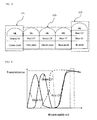
FIG. 1 is a diagram illustrating the configuration of an image sensor of an embodiment; -
FIG. 2 is a diagram illustrating a state in which a second sensing unit is provided in the vicinity of a first sensing unit; -
FIG. 3 is a detailed diagram illustrating of the configuration of a second sensing unit shown inFIG. 2 ; -
FIG. 4 is a graph illustrating transmittance of an IR transmittance filter; and -
FIG. 5 is a graph illustrating determination of proximity to an object by using variation of an output voltage from a proximity detector. - Referring to
FIG. 1 , animage sensor 100 includes alight source unit 110, alight source controller 120, aninfrared transmission filter 150, afirst sensing unit 160 and asecond sensing unit 170. - The
light source unit 110 irradiates infrared with a wavelength of a specific band onto anobject 130. Thelight source unit 110 may include an infrared light emitting diode (LED) that irradiates infrared with a wavelength of 850nm onto theobject 130. - The
light source controller 120 includes anLED controller 121 that generates a control signal for controlling on/off of thelight source unit 110, and anLED driver 122 that controls power supplied to thelight source unit 110 based on the control signal. - The
infrared transmission filter 150 allows only infrared and visible ray with a wavelength of a specific band among light introduced through alens 140 after being reflected by theobject 130 to selectively transmit therethrough. - The
first sensing unit 160 includes an image pixel to acquire an image of theobject 130 introduced through theinfrared transmission filter 150. - The
second sensing unit 170 receives the infrared and visible ray with the wavelength of the specific band, which have passed through theinfrared transmission filter 150, and measures current illumination, proximity to theobject 130 and color temperature of theobject 130. - As shown in
FIG. 2 , thesecond sensing unit 170 is separately provided in the vicinity of thefirst sensing unit 160 while independently operating without a connection to the image pixel of thefirst sensing unit 160. - As shown in
FIG. 3 , thesecond sensing unit 170 includes anillumination detector 171, aproximity detector 172 and acolor temperature detector 173. - The
illumination detector 171 receives the infrared and visible ray with the wavelength of the specific band, which have passed through theinfrared transmission filter 150, and measures the current illumination. - The
proximity detector 172 receives the infrared with the wavelength of the specific band, which has passed through theinfrared transmission filter 150, and measures proximity to theobject 130 based on a difference between output voltages according to the on/off of thelight source unit 110. - The
color temperature detector 173 generates an output voltage based on the visible ray with the wavelength of the specific band, which has passed through theinfrared transmission filter 150, and measures color temperature of theobject 130. - As shown in
FIGS. 2 and3 , theillumination detector 171 may be provided in a plural number throughout thesecond sensing unit 170 in order to easily measure the brightness of light introduced from the exterior of thelens 140. Theproximity detector 172 for determining the proximity to theobject 130 and thecolor temperature detector 173 may also be provided in a plural number throughout thesecond sensing unit 170, similarly to theillumination detector 171. - Meanwhile,
FIG. 3 shows the case in which a separate green pixel is used as theillumination detector 171. However, it is possible to measure the current illumination by using a green pixel provided in thecolor temperature detector 173, instead of the separate green pixel. - Herein, the
illumination detector 171 detects the brightness of the external light incident into thesecond sensing unit 170 after being reflected by theobject 130 and passing through thelens 140. In general, theillumination detector 171 is designed to have a spectrum the same as a brightness curve perceived by the human eye. Furthermore, theillumination detector 171 is provided in a plural number at an outside of thefirst sensing unit 160 including the image pixel while being adjacent thereto, so that an average of light reflected by theobject 130 and thus the current illumination due to the external light can be relatively accurately measured from the average of the light. - In an embodiment, the
proximity detector 172 includes an infrared (IR) pixel and further includes a blur (B) color filter and a red (R) color filter on the IR pixel. Furthermore, theproximity detector 172 generates output voltage values based on the infrared with the wavelength of the specific band, which is introduced into thelens 140 after being irradiated from thelight source unit 140 and reflected by theobject 130. - Moreover, the blur (B) color filter and the red (R) color filter installed on the IR pixel of the
proximity detector 172 serves as a visible ray cut-off filter that cuts off visible ray introduced after transmitting through thelens 140. As described above, the visible ray cut-off filter is provided on the infrared (IR) pixel of theproximity detector 172, so that the visible ray is prevented from reaching theproximity detector 172, and a difference between the output voltage values caused by only the infrared with the wavelength of the specific band, which is reflected by theobject 130, is calculated, resulting in the improvement of the accuracy of proximity determination. - The
color temperature detector 173 includes a red (R) pixel, a green (G) pixel and a blue (B) pixel, detects an output voltage based on the visible ray with the wavelength of the specific band, which has passed through theinfrared transmission filter 150, and measures the color temperature of theobject 130. Furthermore, a red (R) color filter, a green (G) color filter and a blue (B) color filter may be provided on the red (R) pixel, the green (G) pixel and the blue (B) pixel, respectively. - In detail, the red (R) pixel, the green (G) pixel and the blue (B) pixel are installed separately from an area in which the image pixel of the
first sensing unit 160 is installed, and operate separately from the image pixel of thefirst sensing unit 160. Consequently, when measuring the color temperature of theobject 130, R, G and B pixels provided in thecolor temperature detector 173 are used without directly using an image pixel causing high power consumption, so that the color temperature of theobject 130 can be easily measured while reducing power consumption. - Referring to
FIG. 4 , it can be understood that the IR transmittance filter allows light with a wavelength of 400nm to 650nm (a visible ray area) in order to acquire an image, cuts off light in an infrared area which degrades color characteristics, and allows only infrared with a specific wavelength of 850nm band, which serves as a light source for determining the proximity of an object or a light source as an illumination for measuring the color temperature thereof, to transmit therethrough. - As described above, only the wavelength of the visible ray area and the wavelength of the specific band in the discontinuous infrared area are transmitted by the IR transmittance filter, so that degradation of color characteristics can be minimized, and the infrared LED can be utilized as a light source for the proximity determination and color temperature measurement of the object as well as a simple light source.
- Referring to
FIG. 5 , V1 denotes an output voltage value measured by theproximity detector 172 based on the light introduced through the lens when thelight source unit 110 irradiating infrared with the wavelength of 850nm band is turned on, V2 denotes an output voltage value output from theproximity detector 172 when thelight source unit 110 is turned off, and ΔVd denotes the difference between V1 and V2. - The intensity of the light incident into the
proximity detector 172 after being reflected by theobject 130 when thelight source unit 110 is turned off is determined only by the intensity of external light. However, the intensity of the light incident into theproximity detector 172 after being reflected by theobject 130 when thelight source unit 110 is turned on is determined by the sum of the intensity of the external light and the intensity of the light emitted from thelight source unit 110. - Accordingly, the difference between the output value V2 from the
proximity detector 172 when thelight source unit 110 is in the turned off state and the output value V1 from theproximity detector 172 when thelight source unit 110 is in the turned on state is determined only by the relationship between the light emitted from thelight source unit 110 and the object, regardless of the external light. Furthermore, the ΔVd value depends on the distance between theobject 130 and thelight source unit 110. - That is, when the same object is far from the
light source unit 110, the amount of the light incident into theproximity detector 172 after being emitted from thelight source unit 110 and reflected by the object is extremely small. However, when the object gradually approaches thelight source unit 110, the amount of the light incident into theproximity detector 172 after being emitted from thelight source unit 110 and reflected by the object is increased, and thus the ΔVd value is increased. - Accordingly, when the ΔVd value is large, the
proximity detector 172 determines that the object approaches thelight source unit 110 since a large amount of the infrared emitted from thelight source unit 110 is introduced after being reflected by the object. However, when the ΔVd value is small, theproximity detector 172 determines that the object is far from thelight source unit 110 since a small amount of the infrared emitted from thelight source unit 110 is introduced after being reflected by the object. - That is, since the ΔVd value is proportional to the reflectivity R of the object while being inverse proportional to the square of the distance d between the
proximity detector 172 and the object, when the distance d is very large (long distance), the output value from theproximity detector 172 shows less difference between when thelight source unit 110 is in the turned on state and when thelight source unit 110 is in the turned off state. However, the distance d is small (proximity distance), the output value from theproximity detector 172 shows significant difference between when thelight source unit 110 is in the turned on state and when thelight source unit 110 is in the turned off state. Accordingly, the difference ΔVd between the output values is calculated, so that the distance d to the object can be accurately calculated. - Actually, the turn-on time interval Δt of the
light source unit 110 may be repeated three or five times at a time of 0.1sec or less in order to calculate the distance d to the object more accurately. - As described above, by the use of both the LED irradiating the light with the wavelength of the specific band (e.g., 850nm) and the IR transmittance filter allowing the light of the specific band introduced into the lens after being irradiated from the light source and reflected by the object, variation of the output voltage values from the
proximity detector 172 is calculated according to the existence or absence of the light of the specific band, so that the proximity to the object can be easily determined. - Moreover, for the illumination measurement, the proximity determination of the object and the color temperature measurement of the object, respective light sources are not separately provided and the single LED is used, so that the illumination measurement, the proximity determination and the color temperature measurement can be easily realized while preventing an increase in the size of the system using the image sensor.
- In the case in which the
light source unit 110 is formed of the infrared LED irradiating the infrared with the wavelength of 850nm band, when thelight source unit 110 is turned on for illumination when photographing at night or for the proximity determination and the color temperature measurement, persons do not feel dazzling and has difficulty in recognizing flicker of the infrared LED. However, since the sensitivity of the sensor detecting the light reflected by the object is increased, more accurate images can be achieved and the proximity and color temperature measurement can be performed more accurately. - Furthermore, the infrared of 850nm band is used as a light source and infrared except for 850nm band is cut off by the IR transmission filter, so that the degradation of color characteristics can be minimized. That is, when using the IR transmission filter as a light source when photographing at night or a light source for the proximity determination and the color temperature measurement, the IR transmission filter serves as a transmission filter that allows the infrared of 850nm band to transmit therethrough. However, when photographing in the daytime, the IR transmission filter serves as an infrared cut-off filter that cuts off infrared with wavelengths of bands except for 850nm band. As a result, the degradation of color characteristics can be minimized.
- In this regard, in the case of using the LED as a light source when photographing at night, the
LED controller 121 may generate a turn-on signal for the LED based on an external control signal in order to acquire images. In the case of using the LED as a light source for the proximity determination and the color temperature measurement, theLED controller 121 may generate a control signal for allowing turn-on and turn-off of the LED to be repeated in plural times for a predetermined time. - According to the embodiment, a control signal for the proximity determination and the color temperature measurement may be generated to allow the turn-on and turn-off of the LED to be repeated about three to five times while the turn-on time of the LED is maintained at 0.1second or less. Consequently, the difference between output voltage values from the sensor unit can be measured more quickly and accurately according to the existence or absence of the light irradiated from the LED.
- Furthermore, when acquiring images in a night mode in which an external light source is weak, the image of the
object 130 is acquired by using the light irradiated from the LED as a light source. - At this time, the night mode can be selected when the brightness of the LED in the turned off state is lower than a reference value. Accordingly, when the brightness of an image is very low during the operation of the image sensor, that is, when the night mode is selected since the intensity of the light incident into the
illumination detector 171 provided in thesecond sensing unit 170 is low, the LED is used as a light source by turning on the LED. As described above, in the case of using the LED as a light source when photographing at night, the LED may be selected to have a wavelength of an appropriate band enough to prevent persons from feeling dazzling according to the curve of sensitivity versus wavelengths of the image sensor. - The embodiment describes an example in which the
light source unit 110 is formed of the infrared LED that irradiates the infrared with the wavelength of 850nm. However, the wavelength of the specific band of the light irradiated from the LED is not limited thereto. For example, various wavelengths may be selected according to the characteristics of the infrared transmission filter. - An embodiment of the present invention has been described for illustrative purposes. Those skilled in the art will appreciate that various modifications, additions and substitutions are possible, without departing from the scope of the invention as defined in the accompanying claims.
Claims (11)
- An image sensor for measuring illumination, proximity and color temperature, comprising:a light source unit configured to irradiate infrared with a wavelength of a specific band onto an object;a light source controller configured to control power supplied to the light source unit;an infrared transmission filter configured to allow only the infrared and visible ray with the wavelength of the specific band among light incident through a lens after being reflected by the object to selectively transmit therethrough;a first sensing unit provided with an image pixel for acquiring an image of the object introduced through the infrared transmission filter; anda second sensing unit configured to receive the infrared and the visible ray having passed through the infrared transmission filter and measure current illumination, proximity to the object and color temperature of the object.
- An image sensor according to claim 1, wherein the second sensing unit is provided separately from the first sensing unit while operating separately from the first sensing unit.
- An image sensor according to claim 2, wherein the second sensing unit comprises:an illumination detector configured to receive external light having passed through the infrared transmission filter and measure the illumination;a proximity detector configured to receive the infrared having passed through the infrared transmission filter and measure the proximity to the object based on a difference between output voltages according to on/off of the light source unit; anda color temperature detector configured to generate an output voltage based on the visible ray with the wavelength of the specific band, which has passed through the infrared transmission filter, and measure the color temperature of the object.
- An image sensor according to claim 3, wherein the proximity detector comprises an infrared sensor (IR pixel), and is configured to compare an output voltage value from the infrared sensor when the light source unit is a turned off state with an output voltage value from the infrared sensor when the light source unit is a turned on state and detect the proximity to the object.
- An image sensor according to claim 4, wherein the proximity detector further comprises a visible ray cut-off filter provided on the infrared sensor.
- An image sensor according to claim 3, wherein the color temperature detector comprises a red (R) pixel, a green (G) pixel and a blue (B) pixel, and is configured to detect an output voltage based on the visible ray with the wavelength of the specific band, which has passed through the infrared transmission filter, and measure the color temperature of the object.
- An image sensor according to any one of claims 1 to 6, wherein the light source unit includes an infrared light emitting diode that irradiates infrared with a wavelength of 850nm.
- An image sensor according to claim 7, wherein the infrared transmission filter is configured to allow the visible ray with a wavelength of 400nm to 650nm and the infrared with the wavelength of 850nm to transmit therethrough.
- An image sensor according to claim 8, wherein the light source controller is configured to turn on the infrared light emitting diode as a light source when photographing at night if illumination measured by the illumination detector receiving the external light having passed through the infrared transmission filter is equal to or less than a reference value.
- An image sensor according to claim 8, wherein, when the infrared light emitting diode is used as a light source for proximity determination, the light source controller is configured to control turn-on and turn-off of the infrared light emitting diode to be repeated at plural times for a predetermined time.
- An image sensor according to claim 10, wherein the light source controller is configured to control the turn-on and turn-off of the infrared light emitting diode to be repeated three to five times while maintaining a turn-on time of the infrared light emitting diode at 0.1second or less.
Applications Claiming Priority (1)
| Application Number | Priority Date | Filing Date | Title |
|---|---|---|---|
| KR1020090051639A KR101048768B1 (en) | 2009-06-10 | 2009-06-10 | Image sensor for measuring illuminance, proximity and color temperature |
Publications (3)
| Publication Number | Publication Date |
|---|---|
| EP2261690A2 true EP2261690A2 (en) | 2010-12-15 |
| EP2261690A3 EP2261690A3 (en) | 2012-01-04 |
| EP2261690B1 EP2261690B1 (en) | 2017-04-05 |
Family
ID=42727041
Family Applications (1)
| Application Number | Title | Priority Date | Filing Date |
|---|---|---|---|
| EP10164770.9A Active EP2261690B1 (en) | 2009-06-10 | 2010-06-02 | Image sensor for measuring illumination, proximity and color temperature |
Country Status (6)
| Country | Link |
|---|---|
| US (1) | US8658975B2 (en) |
| EP (1) | EP2261690B1 (en) |
| JP (1) | JP4884552B2 (en) |
| KR (1) | KR101048768B1 (en) |
| CN (2) | CN101922966A (en) |
| TW (1) | TWI422023B (en) |
Cited By (3)
| Publication number | Priority date | Publication date | Assignee | Title |
|---|---|---|---|---|
| EP2857813A1 (en) * | 2013-10-04 | 2015-04-08 | ams AG | Colour sensor arrangement and method for colour sensor calibration |
| EP2871834A1 (en) * | 2013-11-12 | 2015-05-13 | Samsung Electronics Co., Ltd | Method for performing sensor function and electronic device thereof |
| WO2016191827A1 (en) * | 2015-06-05 | 2016-12-08 | Seeing Machines Limited | Protective system for infrared light source |
Families Citing this family (88)
| Publication number | Priority date | Publication date | Assignee | Title |
|---|---|---|---|---|
| US9756264B2 (en) | 2009-03-02 | 2017-09-05 | Flir Systems, Inc. | Anomalous pixel detection |
| US9473681B2 (en) | 2011-06-10 | 2016-10-18 | Flir Systems, Inc. | Infrared camera system housing with metalized surface |
| US9208542B2 (en) | 2009-03-02 | 2015-12-08 | Flir Systems, Inc. | Pixel-wise noise reduction in thermal images |
| US9635285B2 (en) | 2009-03-02 | 2017-04-25 | Flir Systems, Inc. | Infrared imaging enhancement with fusion |
| US10244190B2 (en) | 2009-03-02 | 2019-03-26 | Flir Systems, Inc. | Compact multi-spectrum imaging with fusion |
| US9998697B2 (en) | 2009-03-02 | 2018-06-12 | Flir Systems, Inc. | Systems and methods for monitoring vehicle occupants |
| US9986175B2 (en) | 2009-03-02 | 2018-05-29 | Flir Systems, Inc. | Device attachment with infrared imaging sensor |
| US9843742B2 (en) | 2009-03-02 | 2017-12-12 | Flir Systems, Inc. | Thermal image frame capture using de-aligned sensor array |
| US9674458B2 (en) | 2009-06-03 | 2017-06-06 | Flir Systems, Inc. | Smart surveillance camera systems and methods |
| US9451183B2 (en) | 2009-03-02 | 2016-09-20 | Flir Systems, Inc. | Time spaced infrared image enhancement |
| US9948872B2 (en) | 2009-03-02 | 2018-04-17 | Flir Systems, Inc. | Monitor and control systems and methods for occupant safety and energy efficiency of structures |
| US9517679B2 (en) | 2009-03-02 | 2016-12-13 | Flir Systems, Inc. | Systems and methods for monitoring vehicle occupants |
| US10757308B2 (en) | 2009-03-02 | 2020-08-25 | Flir Systems, Inc. | Techniques for device attachment with dual band imaging sensor |
| USD765081S1 (en) | 2012-05-25 | 2016-08-30 | Flir Systems, Inc. | Mobile communications device attachment with camera |
| US9235876B2 (en) | 2009-03-02 | 2016-01-12 | Flir Systems, Inc. | Row and column noise reduction in thermal images |
| US9292909B2 (en) | 2009-06-03 | 2016-03-22 | Flir Systems, Inc. | Selective image correction for infrared imaging devices |
| US9843743B2 (en) | 2009-06-03 | 2017-12-12 | Flir Systems, Inc. | Infant monitoring systems and methods using thermal imaging |
| US9819880B2 (en) | 2009-06-03 | 2017-11-14 | Flir Systems, Inc. | Systems and methods of suppressing sky regions in images |
| US9716843B2 (en) | 2009-06-03 | 2017-07-25 | Flir Systems, Inc. | Measurement device for electrical installations and related methods |
| US10091439B2 (en) | 2009-06-03 | 2018-10-02 | Flir Systems, Inc. | Imager with array of multiple infrared imaging modules |
| US9756262B2 (en) | 2009-06-03 | 2017-09-05 | Flir Systems, Inc. | Systems and methods for monitoring power systems |
| US9706138B2 (en) | 2010-04-23 | 2017-07-11 | Flir Systems, Inc. | Hybrid infrared sensor array having heterogeneous infrared sensors |
| US9207708B2 (en) | 2010-04-23 | 2015-12-08 | Flir Systems, Inc. | Abnormal clock rate detection in imaging sensor arrays |
| US9918023B2 (en) | 2010-04-23 | 2018-03-13 | Flir Systems, Inc. | Segmented focal plane array architecture |
| US9848134B2 (en) | 2010-04-23 | 2017-12-19 | Flir Systems, Inc. | Infrared imager with integrated metal layers |
| JP5625707B2 (en) * | 2010-10-04 | 2014-11-19 | ソニー株式会社 | SEMICONDUCTOR DEVICE, ELECTRONIC DEVICE, AND SEMICONDUCTOR DEVICE MANUFACTURING METHOD |
| US9143703B2 (en) | 2011-06-10 | 2015-09-22 | Flir Systems, Inc. | Infrared camera calibration techniques |
| US10079982B2 (en) | 2011-06-10 | 2018-09-18 | Flir Systems, Inc. | Determination of an absolute radiometric value using blocked infrared sensors |
| US9058653B1 (en) | 2011-06-10 | 2015-06-16 | Flir Systems, Inc. | Alignment of visible light sources based on thermal images |
| US10389953B2 (en) | 2011-06-10 | 2019-08-20 | Flir Systems, Inc. | Infrared imaging device having a shutter |
| US9961277B2 (en) | 2011-06-10 | 2018-05-01 | Flir Systems, Inc. | Infrared focal plane array heat spreaders |
| US10169666B2 (en) | 2011-06-10 | 2019-01-01 | Flir Systems, Inc. | Image-assisted remote control vehicle systems and methods |
| US9706137B2 (en) | 2011-06-10 | 2017-07-11 | Flir Systems, Inc. | Electrical cabinet infrared monitor |
| US10051210B2 (en) | 2011-06-10 | 2018-08-14 | Flir Systems, Inc. | Infrared detector array with selectable pixel binning systems and methods |
| US9235023B2 (en) | 2011-06-10 | 2016-01-12 | Flir Systems, Inc. | Variable lens sleeve spacer |
| WO2012170954A2 (en) | 2011-06-10 | 2012-12-13 | Flir Systems, Inc. | Line based image processing and flexible memory system |
| CN103748867B (en) | 2011-06-10 | 2019-01-18 | 菲力尔系统公司 | Low Power and Small Form Factor Infrared Imaging |
| US10841508B2 (en) | 2011-06-10 | 2020-11-17 | Flir Systems, Inc. | Electrical cabinet infrared monitor systems and methods |
| KR101778353B1 (en) | 2011-06-10 | 2017-09-13 | 플리어 시스템즈, 인크. | Non-uniformity correction techniques for infrared imaging devices |
| US9509924B2 (en) | 2011-06-10 | 2016-11-29 | Flir Systems, Inc. | Wearable apparatus with integrated infrared imaging module |
| US9900526B2 (en) | 2011-06-10 | 2018-02-20 | Flir Systems, Inc. | Techniques to compensate for calibration drifts in infrared imaging devices |
| US8826188B2 (en) * | 2011-08-26 | 2014-09-02 | Qualcomm Incorporated | Proximity sensor calibration |
| JP5879937B2 (en) * | 2011-11-02 | 2016-03-08 | 株式会社リコー | Imaging unit |
| US20140014839A1 (en) * | 2012-07-11 | 2014-01-16 | Tom Chang | Sensor design based on light sensing |
| US9811884B2 (en) | 2012-07-16 | 2017-11-07 | Flir Systems, Inc. | Methods and systems for suppressing atmospheric turbulence in images |
| WO2014014957A1 (en) | 2012-07-16 | 2014-01-23 | Flir Systems, Inc. | Methods and systems for suppressing noise in images |
| US20140098063A1 (en) * | 2012-10-10 | 2014-04-10 | Research In Motion Limited | Electronic device with proximity sensing |
| CN102883106A (en) * | 2012-10-18 | 2013-01-16 | 信利光电(汕尾)有限公司 | Method of applying light sensor on camera module and terminal equipment |
| KR101457069B1 (en) * | 2012-12-13 | 2014-10-31 | (주)신오전자 | Optical proximity sensor with ambient light sensor |
| KR101402838B1 (en) | 2012-11-12 | 2014-06-03 | 주식회사 동부하이텍 | An apparatus for sensing an intensity of illumination and a proximity |
| JP6170673B2 (en) | 2012-12-27 | 2017-07-26 | 富士フイルム株式会社 | Composition for color filter, infrared transmission filter, method for producing the same, and infrared sensor |
| CN103051839A (en) * | 2012-12-27 | 2013-04-17 | 武汉烽火众智数字技术有限责任公司 | Device and method for intelligently adjusting light supplementation angle |
| CN104102337A (en) * | 2013-04-08 | 2014-10-15 | 普雷森株式会社 | Method and apparatus for determining proximity level between user and electronic device |
| JP6200204B2 (en) * | 2013-05-17 | 2017-09-20 | 日本放送協会 | Lighting information measuring device |
| KR101416000B1 (en) * | 2013-05-27 | 2014-07-08 | 마루엘에스아이 주식회사 | Illumination proximity sensor and optical sensing device used therefor |
| KR20140147376A (en) * | 2013-06-19 | 2014-12-30 | 삼성전자주식회사 | Layered type color-depth sensor and 3D image acquisition apparatus employing the sensor |
| KR102102702B1 (en) * | 2013-06-19 | 2020-04-21 | 삼성전자주식회사 | Unit pixel of image sensor and image sensor having the same |
| KR102054774B1 (en) | 2013-09-10 | 2019-12-11 | 삼성전자주식회사 | Image device including dynamic vision sensor, ambient light sensor, and proximity sensor |
| KR102071325B1 (en) * | 2013-09-27 | 2020-04-02 | 매그나칩 반도체 유한회사 | Optical sensor sensing illuminance and proximity |
| US9973692B2 (en) | 2013-10-03 | 2018-05-15 | Flir Systems, Inc. | Situational awareness by compressed display of panoramic views |
| KR102159996B1 (en) | 2013-12-16 | 2020-09-25 | 삼성전자주식회사 | Event filtering device and motion recognition device thereof |
| US11297264B2 (en) | 2014-01-05 | 2022-04-05 | Teledyne Fur, Llc | Device attachment with dual band imaging sensor |
| US10262412B2 (en) * | 2014-04-03 | 2019-04-16 | Nippon Steel & Sumitomo Metal Corporation | Welded state monitoring system and welded state monitoring method |
| CN103941310B (en) * | 2014-04-09 | 2017-02-15 | 苏州佳世达电通有限公司 | Correcting method and system of proximity sensor |
| CN104038899B (en) * | 2014-06-11 | 2019-02-22 | 北京智谷睿拓技术服务有限公司 | Proximity relations determines method and device |
| KR102331920B1 (en) | 2014-12-26 | 2021-11-29 | 삼성전자주식회사 | Sensor for motion information, illumination information and proximity information, and method for operating processor using the sensor |
| EP3424276A1 (en) * | 2016-03-02 | 2019-01-09 | Philips Lighting Holding B.V. | Method for determining contribution and orientation of light sources at a predetermined measurement point |
| JP6690092B2 (en) * | 2016-07-27 | 2020-04-28 | 富士通株式会社 | Heat source detection device, heat source detection method, and heat source detection program |
| CN111028188B (en) * | 2016-09-19 | 2023-05-02 | 杭州海康威视数字技术股份有限公司 | Light-splitting fusion image acquisition equipment |
| US10701244B2 (en) * | 2016-09-30 | 2020-06-30 | Microsoft Technology Licensing, Llc | Recolorization of infrared image streams |
| CN106768384B (en) * | 2016-12-06 | 2020-07-14 | 清华大学 | Color imaging temperature field measuring device and method based on auxiliary frequency modulation light source |
| US10141359B2 (en) | 2017-03-01 | 2018-11-27 | Himax Technologies Limited | Image sensor |
| CN107807270B (en) * | 2017-11-29 | 2023-06-27 | 曲阜师范大学 | A current detection device and detection method based on artificial intelligence |
| CN107920236A (en) * | 2017-12-18 | 2018-04-17 | 广东欧珀移动通信有限公司 | Image white balance processing method and device, storage medium and electronic equipment |
| KR102069660B1 (en) * | 2018-04-05 | 2020-01-23 | 해성디에스 주식회사 | Proximity sensor |
| TWI675248B (en) * | 2018-04-09 | 2019-10-21 | 文曄科技股份有限公司 | Image capturing device |
| CN111436209A (en) * | 2018-11-12 | 2020-07-21 | 深圳市汇顶科技股份有限公司 | Optical sensing device and terminal |
| GB2582786B (en) * | 2019-04-02 | 2022-02-23 | Impression Tech Limited | A non-contact temperature sensor |
| JP7401211B2 (en) * | 2019-06-25 | 2023-12-19 | ファナック株式会社 | Distance measuring device with external light illuminance measurement function and method for measuring external light illuminance |
| JP7323787B2 (en) * | 2019-07-31 | 2023-08-09 | 日亜化学工業株式会社 | Lighting device and lighting device with infrared camera |
| US11315746B2 (en) | 2019-12-31 | 2022-04-26 | Darfon Electronics Corp. | Optical switch keyboard adjustment method and optical switch keyboard using the same |
| CN111551265B (en) * | 2020-04-03 | 2021-05-14 | 深圳市爱图仕影像器材有限公司 | Color temperature measuring method and color temperature measuring device |
| TWI783311B (en) * | 2020-11-30 | 2022-11-11 | 寶力旺健康科技股份有限公司 | Infrared device with color temperature monitoring |
| CN114585113A (en) * | 2020-12-02 | 2022-06-03 | 宝力旺健康科技股份有限公司 | Infrared device with color temperature monitoring |
| KR102477469B1 (en) | 2021-05-28 | 2022-12-13 | 국민대학교산학협력단 | Optic characteristic storage device and system using the same |
| CN113691716B (en) * | 2021-08-26 | 2023-07-11 | 维沃移动通信有限公司 | Image sensor, image processing method, image processing device, electronic apparatus, and storage medium |
| EP4366290B1 (en) * | 2021-09-16 | 2026-04-29 | Samsung Electronics Co., Ltd. | Electronic device comprising camera, and operation method thereof |
| CN118090154A (en) * | 2024-02-05 | 2024-05-28 | 中国科学院半导体研究所 | Laser far-field beam quality testing device and testing method |
Family Cites Families (26)
| Publication number | Priority date | Publication date | Assignee | Title |
|---|---|---|---|---|
| JP2565168B2 (en) | 1986-07-16 | 1996-12-18 | ソニー株式会社 | Imaging device |
| JPH0215793A (en) * | 1988-07-01 | 1990-01-19 | Fuji Photo Film Co Ltd | White balance adjuster |
| JPH07294248A (en) * | 1994-04-28 | 1995-11-10 | Hamamatsu Photonics Kk | Distance measuring equipment |
| US5555464A (en) * | 1995-07-28 | 1996-09-10 | Lockheed Martin Corporation | Red/near-infrared filtering for CCD cameras |
| JPH10108206A (en) | 1996-09-27 | 1998-04-24 | Toshiba Lighting & Technol Corp | Color video camera, TV door phone and monitoring device |
| JPH11155105A (en) | 1997-11-21 | 1999-06-08 | Honda Motor Co Ltd | Image sensor |
| CA2300400A1 (en) * | 1999-03-22 | 2000-09-22 | Michael George Taranowski | Electronic optical target ranging and imaging |
| CA2330433A1 (en) * | 2000-01-21 | 2001-07-21 | Symagery Microsystems Inc. | Smart exposure determination for imagers |
| US6770861B2 (en) * | 2000-03-08 | 2004-08-03 | Minolta Co., Ltd. | Image-sensing device |
| JP4815677B2 (en) * | 2001-02-20 | 2011-11-16 | ソニー株式会社 | Automotive video camera system and automotive outside mirror |
| JP4439767B2 (en) * | 2001-08-09 | 2010-03-24 | キヤノン株式会社 | Imaging apparatus, white balance adjustment method, and operation processing program thereof |
| JP2003101867A (en) | 2001-09-19 | 2003-04-04 | Olympus Optical Co Ltd | Image pickup device |
| JP2003179808A (en) * | 2001-12-13 | 2003-06-27 | Seiko Precision Inc | Image pickup device and portable electronic device |
| US7965336B2 (en) * | 2002-11-14 | 2011-06-21 | Donnelly Corporation | Imaging system for vehicle |
| US20040169748A1 (en) * | 2003-02-28 | 2004-09-02 | Tinku Acharya | Sub-sampled infrared sensor for use in a digital image capture device |
| US20050151053A1 (en) * | 2004-01-08 | 2005-07-14 | Griffin Dennis P. | Infrared proximity sensor for air bag safety |
| JP2006109120A (en) * | 2004-10-06 | 2006-04-20 | Funai Electric Co Ltd | Infrared imaging device |
| US7560679B1 (en) * | 2005-05-10 | 2009-07-14 | Siimpel, Inc. | 3D camera |
| JP4899534B2 (en) * | 2006-02-28 | 2012-03-21 | ソニー株式会社 | Surveillance camera |
| US7375803B1 (en) * | 2006-05-18 | 2008-05-20 | Canesta, Inc. | RGBZ (red, green, blue, z-depth) filter system usable with sensor systems, including sensor systems with synthetic mirror enhanced three-dimensional imaging |
| KR100834621B1 (en) * | 2006-11-22 | 2008-06-02 | 삼성전자주식회사 | Optical receiver for visible light communication and optical communication system using same |
| KR100860699B1 (en) * | 2007-02-12 | 2008-09-26 | 삼성전자주식회사 | Camera system with lens shading correction function using color temperature |
| JP4621270B2 (en) * | 2007-07-13 | 2011-01-26 | キヤノン株式会社 | Optical filter |
| KR100858034B1 (en) * | 2007-10-18 | 2008-09-10 | (주)실리콘화일 | Single chip vitality image sensor |
| KR100992411B1 (en) * | 2009-02-06 | 2010-11-05 | (주)실리콘화일 | Image sensor to determine whether subject is close |
| EP2472853A1 (en) * | 2011-01-03 | 2012-07-04 | STMicroelectronics (Grenoble 2) SAS | Imaging device with ambient light sensing means |
-
2009
- 2009-06-10 KR KR1020090051639A patent/KR101048768B1/en active Active
-
2010
- 2010-06-02 EP EP10164770.9A patent/EP2261690B1/en active Active
- 2010-06-03 US US12/793,066 patent/US8658975B2/en active Active
- 2010-06-08 JP JP2010130592A patent/JP4884552B2/en active Active
- 2010-06-09 CN CN2010101994637A patent/CN101922966A/en active Pending
- 2010-06-09 CN CN201510977722.7A patent/CN105352601A/en active Pending
- 2010-06-10 TW TW099118963A patent/TWI422023B/en active
Non-Patent Citations (1)
| Title |
|---|
| None |
Cited By (5)
| Publication number | Priority date | Publication date | Assignee | Title |
|---|---|---|---|---|
| EP2857813A1 (en) * | 2013-10-04 | 2015-04-08 | ams AG | Colour sensor arrangement and method for colour sensor calibration |
| WO2015049143A1 (en) * | 2013-10-04 | 2015-04-09 | Ams Ag | Colour sensor arrangement and method for colour sensor calibration |
| US10072981B2 (en) | 2013-10-04 | 2018-09-11 | Ams Ag | Color sensor arrangement and method for color sensor calibration |
| EP2871834A1 (en) * | 2013-11-12 | 2015-05-13 | Samsung Electronics Co., Ltd | Method for performing sensor function and electronic device thereof |
| WO2016191827A1 (en) * | 2015-06-05 | 2016-12-08 | Seeing Machines Limited | Protective system for infrared light source |
Also Published As
| Publication number | Publication date |
|---|---|
| JP2010288274A (en) | 2010-12-24 |
| JP4884552B2 (en) | 2012-02-29 |
| EP2261690B1 (en) | 2017-04-05 |
| US8658975B2 (en) | 2014-02-25 |
| TWI422023B (en) | 2014-01-01 |
| KR101048768B1 (en) | 2011-07-15 |
| CN101922966A (en) | 2010-12-22 |
| CN105352601A (en) | 2016-02-24 |
| US20100314543A1 (en) | 2010-12-16 |
| TW201101475A (en) | 2011-01-01 |
| KR20100132846A (en) | 2010-12-20 |
| EP2261690A3 (en) | 2012-01-04 |
Similar Documents
| Publication | Publication Date | Title |
|---|---|---|
| EP2261690B1 (en) | Image sensor for measuring illumination, proximity and color temperature | |
| US8304727B2 (en) | Image sensor capable of judging proximity to subject | |
| EP3033926B1 (en) | An illumination controller | |
| US20140043478A1 (en) | Security camera assembly | |
| US8270042B2 (en) | Document reading apparatus | |
| KR20120139390A (en) | Device, system and method for controlling light source to photograph | |
| US8531528B2 (en) | Image sensor capable of realizing night-photographing and functions of proximity sensor and illuminance sensor | |
| US9693415B1 (en) | Photoelectric switch | |
| US9451667B2 (en) | Optical sensor circuit, luminous panel and method of operating an optical sensor circuit | |
| CN104838644A (en) | Camera system, particularly for a vehicle, and method for determining image information of a detection region | |
| KR102261857B1 (en) | Image sensor and apparatus and method for acquiring image by using the same | |
| JP2006047334A (en) | Projector apparatus and zooming control method | |
| JP5507895B2 (en) | Transmission type measuring device | |
| EP2804047A1 (en) | Optical sensor circuit, luminous panel and method for operating an optical sensor circuit | |
| US12018982B2 (en) | Ambient radiation sensing | |
| US11333554B2 (en) | Spectrometry method and spectrometry apparatus | |
| US20140339986A1 (en) | Optical sensor circuit, luminous panel and method for operating an optical sensor circuit | |
| US9906705B2 (en) | Image pickup apparatus | |
| KR101769155B1 (en) | Camera module and method for driving flash | |
| CN112037732A (en) | Apparatus, system, and storage medium for brightness control of vehicle display based on infrared camera | |
| JP5423277B2 (en) | Switch device and multi-optical axis photoelectric sensor using the switch device | |
| JP2019182256A (en) | Light distribution control device, light projection system, and light distribution control method | |
| KR102384590B1 (en) | Filter and Camera |
Legal Events
| Date | Code | Title | Description |
|---|---|---|---|
| PUAI | Public reference made under article 153(3) epc to a published international application that has entered the european phase |
Free format text: ORIGINAL CODE: 0009012 |
|
| 17P | Request for examination filed |
Effective date: 20100602 |
|
| AK | Designated contracting states |
Kind code of ref document: A2 Designated state(s): AL AT BE BG CH CY CZ DE DK EE ES FI FR GB GR HR HU IE IS IT LI LT LU LV MC MK MT NL NO PL PT RO SE SI SK SM TR |
|
| AX | Request for extension of the european patent |
Extension state: BA ME RS |
|
| PUAL | Search report despatched |
Free format text: ORIGINAL CODE: 0009013 |
|
| AK | Designated contracting states |
Kind code of ref document: A3 Designated state(s): AL AT BE BG CH CY CZ DE DK EE ES FI FR GB GR HR HU IE IS IT LI LT LU LV MC MK MT NL NO PL PT RO SE SI SK SM TR |
|
| AX | Request for extension of the european patent |
Extension state: BA ME RS |
|
| RIC1 | Information provided on ipc code assigned before grant |
Ipc: G01J 3/46 20060101ALI20111201BHEP Ipc: G01S 17/02 20060101AFI20111201BHEP Ipc: G01S 17/89 20060101ALI20111201BHEP |
|
| 17Q | First examination report despatched |
Effective date: 20151022 |
|
| GRAP | Despatch of communication of intention to grant a patent |
Free format text: ORIGINAL CODE: EPIDOSNIGR1 |
|
| INTG | Intention to grant announced |
Effective date: 20161014 |
|
| GRAS | Grant fee paid |
Free format text: ORIGINAL CODE: EPIDOSNIGR3 |
|
| GRAA | (expected) grant |
Free format text: ORIGINAL CODE: 0009210 |
|
| RAP1 | Party data changed (applicant data changed or rights of an application transferred) |
Owner name: SK HYNIX INC. |
|
| AK | Designated contracting states |
Kind code of ref document: B1 Designated state(s): AL AT BE BG CH CY CZ DE DK EE ES FI FR GB GR HR HU IE IS IT LI LT LU LV MC MK MT NL NO PL PT RO SE SI SK SM TR |
|
| REG | Reference to a national code |
Ref country code: GB Ref legal event code: FG4D |
|
| REG | Reference to a national code |
Ref country code: CH Ref legal event code: EP |
|
| REG | Reference to a national code |
Ref country code: AT Ref legal event code: REF Ref document number: 882314 Country of ref document: AT Kind code of ref document: T Effective date: 20170415 |
|
| REG | Reference to a national code |
Ref country code: IE Ref legal event code: FG4D |
|
| REG | Reference to a national code |
Ref country code: DE Ref legal event code: R096 Ref document number: 602010041242 Country of ref document: DE |
|
| REG | Reference to a national code |
Ref country code: FR Ref legal event code: PLFP Year of fee payment: 8 |
|
| REG | Reference to a national code |
Ref country code: NL Ref legal event code: MP Effective date: 20170405 |
|
| REG | Reference to a national code |
Ref country code: LT Ref legal event code: MG4D |
|
| REG | Reference to a national code |
Ref country code: AT Ref legal event code: MK05 Ref document number: 882314 Country of ref document: AT Kind code of ref document: T Effective date: 20170405 |
|
| PG25 | Lapsed in a contracting state [announced via postgrant information from national office to epo] |
Ref country code: NL Free format text: LAPSE BECAUSE OF FAILURE TO SUBMIT A TRANSLATION OF THE DESCRIPTION OR TO PAY THE FEE WITHIN THE PRESCRIBED TIME-LIMIT Effective date: 20170405 |
|
| PG25 | Lapsed in a contracting state [announced via postgrant information from national office to epo] |
Ref country code: ES Free format text: LAPSE BECAUSE OF FAILURE TO SUBMIT A TRANSLATION OF THE DESCRIPTION OR TO PAY THE FEE WITHIN THE PRESCRIBED TIME-LIMIT Effective date: 20170405 Ref country code: NO Free format text: LAPSE BECAUSE OF FAILURE TO SUBMIT A TRANSLATION OF THE DESCRIPTION OR TO PAY THE FEE WITHIN THE PRESCRIBED TIME-LIMIT Effective date: 20170705 Ref country code: HR Free format text: LAPSE BECAUSE OF FAILURE TO SUBMIT A TRANSLATION OF THE DESCRIPTION OR TO PAY THE FEE WITHIN THE PRESCRIBED TIME-LIMIT Effective date: 20170405 Ref country code: GR Free format text: LAPSE BECAUSE OF FAILURE TO SUBMIT A TRANSLATION OF THE DESCRIPTION OR TO PAY THE FEE WITHIN THE PRESCRIBED TIME-LIMIT Effective date: 20170706 Ref country code: LT Free format text: LAPSE BECAUSE OF FAILURE TO SUBMIT A TRANSLATION OF THE DESCRIPTION OR TO PAY THE FEE WITHIN THE PRESCRIBED TIME-LIMIT Effective date: 20170405 Ref country code: FI Free format text: LAPSE BECAUSE OF FAILURE TO SUBMIT A TRANSLATION OF THE DESCRIPTION OR TO PAY THE FEE WITHIN THE PRESCRIBED TIME-LIMIT Effective date: 20170405 Ref country code: AT Free format text: LAPSE BECAUSE OF FAILURE TO SUBMIT A TRANSLATION OF THE DESCRIPTION OR TO PAY THE FEE WITHIN THE PRESCRIBED TIME-LIMIT Effective date: 20170405 |
|
| PG25 | Lapsed in a contracting state [announced via postgrant information from national office to epo] |
Ref country code: IS Free format text: LAPSE BECAUSE OF FAILURE TO SUBMIT A TRANSLATION OF THE DESCRIPTION OR TO PAY THE FEE WITHIN THE PRESCRIBED TIME-LIMIT Effective date: 20170805 Ref country code: LV Free format text: LAPSE BECAUSE OF FAILURE TO SUBMIT A TRANSLATION OF THE DESCRIPTION OR TO PAY THE FEE WITHIN THE PRESCRIBED TIME-LIMIT Effective date: 20170405 Ref country code: SE Free format text: LAPSE BECAUSE OF FAILURE TO SUBMIT A TRANSLATION OF THE DESCRIPTION OR TO PAY THE FEE WITHIN THE PRESCRIBED TIME-LIMIT Effective date: 20170405 Ref country code: BG Free format text: LAPSE BECAUSE OF FAILURE TO SUBMIT A TRANSLATION OF THE DESCRIPTION OR TO PAY THE FEE WITHIN THE PRESCRIBED TIME-LIMIT Effective date: 20170705 Ref country code: PL Free format text: LAPSE BECAUSE OF FAILURE TO SUBMIT A TRANSLATION OF THE DESCRIPTION OR TO PAY THE FEE WITHIN THE PRESCRIBED TIME-LIMIT Effective date: 20170405 |
|
| REG | Reference to a national code |
Ref country code: DE Ref legal event code: R097 Ref document number: 602010041242 Country of ref document: DE |
|
| PG25 | Lapsed in a contracting state [announced via postgrant information from national office to epo] |
Ref country code: CZ Free format text: LAPSE BECAUSE OF FAILURE TO SUBMIT A TRANSLATION OF THE DESCRIPTION OR TO PAY THE FEE WITHIN THE PRESCRIBED TIME-LIMIT Effective date: 20170405 Ref country code: MC Free format text: LAPSE BECAUSE OF FAILURE TO SUBMIT A TRANSLATION OF THE DESCRIPTION OR TO PAY THE FEE WITHIN THE PRESCRIBED TIME-LIMIT Effective date: 20170405 Ref country code: RO Free format text: LAPSE BECAUSE OF FAILURE TO SUBMIT A TRANSLATION OF THE DESCRIPTION OR TO PAY THE FEE WITHIN THE PRESCRIBED TIME-LIMIT Effective date: 20170405 Ref country code: EE Free format text: LAPSE BECAUSE OF FAILURE TO SUBMIT A TRANSLATION OF THE DESCRIPTION OR TO PAY THE FEE WITHIN THE PRESCRIBED TIME-LIMIT Effective date: 20170405 Ref country code: DK Free format text: LAPSE BECAUSE OF FAILURE TO SUBMIT A TRANSLATION OF THE DESCRIPTION OR TO PAY THE FEE WITHIN THE PRESCRIBED TIME-LIMIT Effective date: 20170405 Ref country code: SK Free format text: LAPSE BECAUSE OF FAILURE TO SUBMIT A TRANSLATION OF THE DESCRIPTION OR TO PAY THE FEE WITHIN THE PRESCRIBED TIME-LIMIT Effective date: 20170405 |
|
| REG | Reference to a national code |
Ref country code: CH Ref legal event code: PL |
|
| PLBE | No opposition filed within time limit |
Free format text: ORIGINAL CODE: 0009261 |
|
| STAA | Information on the status of an ep patent application or granted ep patent |
Free format text: STATUS: NO OPPOSITION FILED WITHIN TIME LIMIT |
|
| PG25 | Lapsed in a contracting state [announced via postgrant information from national office to epo] |
Ref country code: SM Free format text: LAPSE BECAUSE OF FAILURE TO SUBMIT A TRANSLATION OF THE DESCRIPTION OR TO PAY THE FEE WITHIN THE PRESCRIBED TIME-LIMIT Effective date: 20170405 Ref country code: IT Free format text: LAPSE BECAUSE OF FAILURE TO SUBMIT A TRANSLATION OF THE DESCRIPTION OR TO PAY THE FEE WITHIN THE PRESCRIBED TIME-LIMIT Effective date: 20170405 |
|
| REG | Reference to a national code |
Ref country code: FR Ref legal event code: PLFP Year of fee payment: 9 |
|
| 26N | No opposition filed |
Effective date: 20180108 |
|
| REG | Reference to a national code |
Ref country code: IE Ref legal event code: MM4A |
|
| PG25 | Lapsed in a contracting state [announced via postgrant information from national office to epo] |
Ref country code: LU Free format text: LAPSE BECAUSE OF NON-PAYMENT OF DUE FEES Effective date: 20170602 Ref country code: IE Free format text: LAPSE BECAUSE OF NON-PAYMENT OF DUE FEES Effective date: 20170602 Ref country code: CH Free format text: LAPSE BECAUSE OF NON-PAYMENT OF DUE FEES Effective date: 20170630 Ref country code: LI Free format text: LAPSE BECAUSE OF NON-PAYMENT OF DUE FEES Effective date: 20170630 |
|
| PG25 | Lapsed in a contracting state [announced via postgrant information from national office to epo] |
Ref country code: SI Free format text: LAPSE BECAUSE OF FAILURE TO SUBMIT A TRANSLATION OF THE DESCRIPTION OR TO PAY THE FEE WITHIN THE PRESCRIBED TIME-LIMIT Effective date: 20170405 |
|
| REG | Reference to a national code |
Ref country code: BE Ref legal event code: MM Effective date: 20170630 |
|
| PG25 | Lapsed in a contracting state [announced via postgrant information from national office to epo] |
Ref country code: BE Free format text: LAPSE BECAUSE OF NON-PAYMENT OF DUE FEES Effective date: 20170630 |
|
| PG25 | Lapsed in a contracting state [announced via postgrant information from national office to epo] |
Ref country code: MT Free format text: LAPSE BECAUSE OF NON-PAYMENT OF DUE FEES Effective date: 20170602 |
|
| PG25 | Lapsed in a contracting state [announced via postgrant information from national office to epo] |
Ref country code: HU Free format text: LAPSE BECAUSE OF FAILURE TO SUBMIT A TRANSLATION OF THE DESCRIPTION OR TO PAY THE FEE WITHIN THE PRESCRIBED TIME-LIMIT; INVALID AB INITIO Effective date: 20100602 |
|
| PG25 | Lapsed in a contracting state [announced via postgrant information from national office to epo] |
Ref country code: CY Free format text: LAPSE BECAUSE OF NON-PAYMENT OF DUE FEES Effective date: 20170405 |
|
| PG25 | Lapsed in a contracting state [announced via postgrant information from national office to epo] |
Ref country code: MK Free format text: LAPSE BECAUSE OF FAILURE TO SUBMIT A TRANSLATION OF THE DESCRIPTION OR TO PAY THE FEE WITHIN THE PRESCRIBED TIME-LIMIT Effective date: 20170405 |
|
| PG25 | Lapsed in a contracting state [announced via postgrant information from national office to epo] |
Ref country code: TR Free format text: LAPSE BECAUSE OF FAILURE TO SUBMIT A TRANSLATION OF THE DESCRIPTION OR TO PAY THE FEE WITHIN THE PRESCRIBED TIME-LIMIT Effective date: 20170405 |
|
| PG25 | Lapsed in a contracting state [announced via postgrant information from national office to epo] |
Ref country code: PT Free format text: LAPSE BECAUSE OF FAILURE TO SUBMIT A TRANSLATION OF THE DESCRIPTION OR TO PAY THE FEE WITHIN THE PRESCRIBED TIME-LIMIT Effective date: 20170405 |
|
| PG25 | Lapsed in a contracting state [announced via postgrant information from national office to epo] |
Ref country code: AL Free format text: LAPSE BECAUSE OF FAILURE TO SUBMIT A TRANSLATION OF THE DESCRIPTION OR TO PAY THE FEE WITHIN THE PRESCRIBED TIME-LIMIT Effective date: 20170405 |
|
| PGFP | Annual fee paid to national office [announced via postgrant information from national office to epo] |
Ref country code: DE Payment date: 20250407 Year of fee payment: 16 |
|
| PGFP | Annual fee paid to national office [announced via postgrant information from national office to epo] |
Ref country code: GB Payment date: 20250407 Year of fee payment: 16 |
|
| PGFP | Annual fee paid to national office [announced via postgrant information from national office to epo] |
Ref country code: FR Payment date: 20250408 Year of fee payment: 16 |