EP2261559A1 - Combustor assembly for gas turbine with combustion-induced total pressure gain - Google Patents
Combustor assembly for gas turbine with combustion-induced total pressure gain Download PDFInfo
- Publication number
- EP2261559A1 EP2261559A1 EP09162306A EP09162306A EP2261559A1 EP 2261559 A1 EP2261559 A1 EP 2261559A1 EP 09162306 A EP09162306 A EP 09162306A EP 09162306 A EP09162306 A EP 09162306A EP 2261559 A1 EP2261559 A1 EP 2261559A1
- Authority
- EP
- European Patent Office
- Prior art keywords
- shock wave
- combustor assembly
- gas
- combustion chamber
- pressure
- Prior art date
- Legal status (The legal status is an assumption and is not a legal conclusion. Google has not performed a legal analysis and makes no representation as to the accuracy of the status listed.)
- Withdrawn
Links
- 238000002485 combustion reaction Methods 0.000 title claims abstract description 137
- 230000035939 shock Effects 0.000 claims abstract description 138
- 230000001902 propagating effect Effects 0.000 claims abstract description 20
- 238000011144 upstream manufacturing Methods 0.000 claims description 7
- 239000007789 gas Substances 0.000 description 122
- 239000000446 fuel Substances 0.000 description 27
- 239000003570 air Substances 0.000 description 20
- 238000000034 method Methods 0.000 description 20
- 230000008569 process Effects 0.000 description 20
- 125000004122 cyclic group Chemical group 0.000 description 11
- 239000012530 fluid Substances 0.000 description 10
- 238000013459 approach Methods 0.000 description 8
- 230000008859 change Effects 0.000 description 7
- 230000006835 compression Effects 0.000 description 7
- 238000007906 compression Methods 0.000 description 7
- 238000004200 deflagration Methods 0.000 description 7
- 238000001816 cooling Methods 0.000 description 5
- 230000000694 effects Effects 0.000 description 5
- 239000007788 liquid Substances 0.000 description 5
- MWUXSHHQAYIFBG-UHFFFAOYSA-N nitrogen oxide Inorganic materials O=[N] MWUXSHHQAYIFBG-UHFFFAOYSA-N 0.000 description 5
- 230000002829 reductive effect Effects 0.000 description 5
- QVGXLLKOCUKJST-UHFFFAOYSA-N atomic oxygen Chemical compound [O] QVGXLLKOCUKJST-UHFFFAOYSA-N 0.000 description 4
- 239000000567 combustion gas Substances 0.000 description 4
- 239000000463 material Substances 0.000 description 4
- 238000002156 mixing Methods 0.000 description 4
- 239000001301 oxygen Substances 0.000 description 4
- 229910052760 oxygen Inorganic materials 0.000 description 4
- 239000007921 spray Substances 0.000 description 4
- 230000003321 amplification Effects 0.000 description 3
- 238000000429 assembly Methods 0.000 description 3
- 230000000712 assembly Effects 0.000 description 3
- 230000006872 improvement Effects 0.000 description 3
- 230000002427 irreversible effect Effects 0.000 description 3
- 238000003199 nucleic acid amplification method Methods 0.000 description 3
- 238000005457 optimization Methods 0.000 description 3
- 230000010355 oscillation Effects 0.000 description 3
- 230000009467 reduction Effects 0.000 description 3
- 238000006243 chemical reaction Methods 0.000 description 2
- 238000005474 detonation Methods 0.000 description 2
- 230000003993 interaction Effects 0.000 description 2
- 238000005184 irreversible process Methods 0.000 description 2
- 239000000203 mixture Substances 0.000 description 2
- 230000003534 oscillatory effect Effects 0.000 description 2
- 230000000644 propagated effect Effects 0.000 description 2
- 239000012080 ambient air Substances 0.000 description 1
- 238000004458 analytical method Methods 0.000 description 1
- 238000010168 coupling process Methods 0.000 description 1
- 238000005859 coupling reaction Methods 0.000 description 1
- 230000001419 dependent effect Effects 0.000 description 1
- 238000010586 diagram Methods 0.000 description 1
- 238000005516 engineering process Methods 0.000 description 1
- 230000007613 environmental effect Effects 0.000 description 1
- 238000002474 experimental method Methods 0.000 description 1
- 239000000284 extract Substances 0.000 description 1
- 238000000605 extraction Methods 0.000 description 1
- CNKHSLKYRMDDNQ-UHFFFAOYSA-N halofenozide Chemical compound C=1C=CC=CC=1C(=O)N(C(C)(C)C)NC(=O)C1=CC=C(Cl)C=C1 CNKHSLKYRMDDNQ-UHFFFAOYSA-N 0.000 description 1
- 230000003116 impacting effect Effects 0.000 description 1
- 238000002347 injection Methods 0.000 description 1
- 239000007924 injection Substances 0.000 description 1
- 230000000670 limiting effect Effects 0.000 description 1
- 238000012423 maintenance Methods 0.000 description 1
- 238000005259 measurement Methods 0.000 description 1
- 230000000737 periodic effect Effects 0.000 description 1
- 230000002093 peripheral effect Effects 0.000 description 1
- 230000000704 physical effect Effects 0.000 description 1
- 230000000717 retained effect Effects 0.000 description 1
- 239000007787 solid Substances 0.000 description 1
- 238000005507 spraying Methods 0.000 description 1
- 230000003068 static effect Effects 0.000 description 1
- 239000000126 substance Substances 0.000 description 1
- 238000012932 thermodynamic analysis Methods 0.000 description 1
- 230000036962 time dependent Effects 0.000 description 1
Images
Classifications
-
- F—MECHANICAL ENGINEERING; LIGHTING; HEATING; WEAPONS; BLASTING
- F23—COMBUSTION APPARATUS; COMBUSTION PROCESSES
- F23C—METHODS OR APPARATUS FOR COMBUSTION USING FLUID FUEL OR SOLID FUEL SUSPENDED IN A CARRIER GAS OR AIR
- F23C99/00—Subject-matter not provided for in other groups of this subclass
- F23C99/003—Combustion process using sound or vibrations
-
- F—MECHANICAL ENGINEERING; LIGHTING; HEATING; WEAPONS; BLASTING
- F23—COMBUSTION APPARATUS; COMBUSTION PROCESSES
- F23R—GENERATING COMBUSTION PRODUCTS OF HIGH PRESSURE OR HIGH VELOCITY, e.g. GAS-TURBINE COMBUSTION CHAMBERS
- F23R3/00—Continuous combustion chambers using liquid or gaseous fuel
- F23R3/02—Continuous combustion chambers using liquid or gaseous fuel characterised by the air-flow or gas-flow configuration
- F23R3/26—Controlling the air flow
-
- F—MECHANICAL ENGINEERING; LIGHTING; HEATING; WEAPONS; BLASTING
- F23—COMBUSTION APPARATUS; COMBUSTION PROCESSES
- F23R—GENERATING COMBUSTION PRODUCTS OF HIGH PRESSURE OR HIGH VELOCITY, e.g. GAS-TURBINE COMBUSTION CHAMBERS
- F23R3/00—Continuous combustion chambers using liquid or gaseous fuel
- F23R3/28—Continuous combustion chambers using liquid or gaseous fuel characterised by the fuel supply
-
- F—MECHANICAL ENGINEERING; LIGHTING; HEATING; WEAPONS; BLASTING
- F23—COMBUSTION APPARATUS; COMBUSTION PROCESSES
- F23R—GENERATING COMBUSTION PRODUCTS OF HIGH PRESSURE OR HIGH VELOCITY, e.g. GAS-TURBINE COMBUSTION CHAMBERS
- F23R7/00—Intermittent or explosive combustion chambers
Definitions
- the present invention relates to a combustor assembly for combusting fuel within a combustion chamber. Furthermore, the invention relates to a gas turbine comprising such combustor assembly.
- combustion of a fuel takes place within a combustor assembly positioned between a compressor and a turbine.
- Oxygen-containing gas enters a combustion chamber at a gas inlet and continuously flows at a substantially stationary flow rate through the combustion chamber towards a gas outlet.
- Fuel is added to the incoming gas and is ignited and combusted within the combustion chamber.
- Such combustion chambers conventionally operate isobaric, i.e. the combustion is effected at an essentially constant pressure throughout the combustion process.
- a total pressure loss in the order of 3% to 4% usually occurs due to mixing losses or friction losses thereby contributing to a reduction of a thermal efficiency of the gas turbine.
- the efficiency of a gas turbine cycle is influenced by losses of each component of the gas turbine, i.e. the compressor, the combustor assembly and the turbine.
- the entropy is an indication of the losses generated in a thermodynamic system.
- the entropy is the portion of the energy content of a system which cannot be used for useful work and is therefore lost due to irreversible processes in the system.
- exergy portion of an energy content of a system which, in relation to a specific environmental condition, may be completely converted to useful work or, in other words, maximum work extraction possible during a thermodynamic process that brings the system into equilibrium with a heat reservoir
- the generated entropy corresponding to an exergy loss due to irreversible combustion in the combustion chamber contributes about 22% of overall losses in a gas turbine. Accordingly, such exergy loss contributes the largest portion to the overall losses in a gas turbine and is about 30 times higher than the losses in the high pressure turbine.
- Thermodynamic analysis of the gas turbine process shows that with a moderate pressure increase within the combustion chamber of 10 - 20%, an increase in the thermal gas turbine efficiency of up to 10% and correspondingly a reduction in the fuel consumption in the same order of magnitude may be obtained.
- improving the efficiency of the combustor assembly within a gas turbine may substantially contribute to an optimization of the gas turbine with respect to its power and its efficiency.
- combustion chamber has been mainly further developed in order to maintain and resist to higher combustion temperatures in order to thereby improve the efficiency of the gas turbine.
- modem gas turbines such as for example gas turbines used in aircraft still operate with an isobaric stationary combustion.
- a combustor assembly with an increased efficiency potential with regard to the thermal cycle efficiency of a gas turbine comprising such combustor assembly.
- a combustor assembly generating a pressure rise between an inlet and an outlet.
- a pressure increase in a combustion chamber may be realized by interaction of shock waves or compression pulses with a flame burning in the combustion chamber.
- the energy needed for generating the shock waves may be less than the additional energy generated in the combustor assembly as a result of such combustion-induced pressure increase.
- the propagating shock waves are emitted in a direction towards a flame region of the combustion chamber in which the combustion of the injected fuel takes place.
- important effects may occur. These effects may be described with reference to the so-called Rayleigh-criterion.
- the Rayleigh-criterion teaches that an amplification of a pressure amplitude may be obtained when a periodical pressure oscillation and an oscillating heat release or enthalpy supply are superimposed in phase. In other words, if the periodic heat release is in phase with the pressure oscillation, the pressure oscillation will be amplified.
- This Rayleigh-criterion is known for more than 130 years and has been typically used to identify situations in which oscillatory combustion is promoted in order to, after such identification, suppress such unwanted oscillatory combustion.
- the physical effects on which the Rayleigh-criterion is based have never been used to generate a combustion-induced increase of the total pressure within a combustion chamber.
- a temporary increase in the heat release rate and in the flame temperature may occur due to the increased pressure and/or due to an increased mixing of fuel and air as a result of turbulences.
- this temporary increase in flame temperature and heat release substantially coincides, i.e. is coupled in phase, with the pressure increase due to the crossing shock wave, the Rayleigh-criterion is fulfilled and thus a further amplification of the total pressure increase may be obtained.
- the shock wave may be further accelerated when entering the flame region with its elevated heat release rate.
- the increased pressure level of the gas together with the increased kinetic energy of the fluid flowing through the combustion chamber may result in an increase of the total pressure of the fluid at the outlet of the combustion chamber.
- thermodynamic terms this means that, although the temperature of the combustion gases at the outlet of the combustion chamber may be the same as in conventional combustion chambers, less energy is lost during the combustion due to a less irreversible energy conversion process. This may result in an overall increase of the efficiency of the gas turbine cycle.
- the increase in the total pressure is not simply a result of the shock waves propagating through the combustion chamber which themselves already induce a certain pressure increase. Instead, there is an additional pressure gain due to fulfilling the Rayleigh-criterion. It is mainly this additional gain in total pressure which provides an improvement of the combustor assembly when compared with conventional combustor assemblies. In other words, the achieved gas turbine efficiency gain due to combustor pressure-gain overcompensates the additional energy input necessary for generating the shock waves.
- a combustor assembly comprising a combustion chamber, a gas inlet for providing gas to the combustion chamber, a gas outlet for exhausting gas from the combustion chamber, a flame generator for generating a flame in a flame region within the combustion chamber and a shock wave generator for generating a propagating shock wave is proposed.
- the combustor assembly is adapted such that the generated shock wave propagates towards the flame region.
- the combustor assembly may be provided with a combustion chamber having features of conventional combustion chambers as for example used in gas turbines for aircraft.
- the combustion chamber may comprise a high-temperature resistant housing enclosing a combustion volume.
- oxygen-containing gas such as compressed ambient air may be provided to the combustion chamber via a gas inlet.
- the supplied gas may be enriched with a fuel in order to provide a highly flammable gas to the combustion chamber.
- the fuel is injected into the incoming gas flow as a gas or in the form of dispersed liquid droplets.
- the gas While the gas enters the combustion chamber usually with a substantial velocity as it comes for example from the compressor of a gas turbine using the combustor assembly, the continuous gas flow from the gas inlet to the gas outlet will occur at subsonic velocities. At the gas outlet, the gas flow may be exhausted from the combustion chamber and may then enter for example a turbine stage of an enclosing gas turbine.
- the fuel- and oxygen-containing combustion gas may be ignited within the combustion chamber and may then combust within a flame region. Without shock wave s crossing the flame region, the flame region would be generally stationary, i.e. the position and the extension of the flame region remain constant throughout a stationary operation of the combustor assembly. However, due to impacting shock wave s, the flame region may move or oscillate within the combustion chamber, as will be described in more detail further below. However, although the position and the extension of the flame region may change upon impact of a shock wave, the combustion within the flame region will never be completely interrupted during normal operation, i.e. the combustion is at least quasi-stationary.
- a continuous gas flow flows through the combustion chamber from the gas inlet to the gas outlet and combustion is continuously taking place within the flame region.
- Such continuous combustion may also be referred to as "deflagration”.
- Deflagration is a technical term describing subsonic combustion that usually propagates through thermal conductivity, i.e. hot burning material heats the next layer of cold material and ignites it. Deflagration may occur in laminar or turbulent gas flows. The velocity of a flame in deflagration may range between approximately 50 m/s up to the speed of sound which itself locally depends on several parameters such as local pressure, local temperature, etc.
- detonation is a process of combustion in which a supersonic shock wave is propagated through a fluid due to an energy release in a reaction zone.
- gas may be compressed to a very high pressure and temperature and then propagates as a shock wave with a velocity much higher than the speed of sound, e.g. with a velocity of Mach 3.
- normal deflagration may occur within the flame region as long as no shock waves propagate through the flame region.
- the local gas pressure as well as the current gas velocity may temporarily increase.
- the temporary gas velocity may exceed the speed of sound during the short duration the shock wave needs to cross the flame region.
- the combusting gases within the flame region may be temporarily entrained and the flame region may be temporarily displaced in a direction towards the gas outlet of the combustion chamber.
- the flame region may return towards its original location corresponding to the normal deflagration position.
- the flame region may oscillate within the combustion chamber at a frequency corresponding to the frequency of shock wave generation.
- shock wave generator being a characteristic feature of the proposed combustor assembly is adapted for generating a propagating shock wave.
- a shock wave sometimes also referred to as "shock front” or simply “shock" is a type of propagating disturbance. Like an ordinary wave, it carries energy and may propagate through a medium, either solid, liquid or gas. Shock waves are characterized by an abrupt, nearly discontinuous change in characteristics of the medium. Across a shock there is always an extreme rise in pressure, temperature and/or density of the medium or the flow of the medium. Contrary to a normal subsonic sound wave, a shock wave travels through a medium at a speed which is higher than the speed of an ordinary wave, i.e.
- shock waves the properties of the fluid such as density, pressure, temperature, velocity, Mach number, etc. may change almost instantaneously. In other words, these parameters do not change their values continuously for example with a sinusoidal behaviour but very abruptly. Measurements of the thickness of shock waves have resulted in values approximately one order of magnitude greater than a mean free path of the gas investigated, roughly micrometers at atmospheric conditions.
- a turbulent gas flow may be induced in the flame region by the crossing shock wave.
- Such turbulences may improve the mixing of fuel with oxygen-containing gas and may thereby result in a temporary temperature rise in the flame region.
- a liquid fuel is injected to the flame region in the form of droplets, such droplets may burst upon impact of a shock wave such that a distribution of the fuel within the flame region may be improved thereby again resulting in a temporary temperature rise.
- the effected increase in heat release rate within the flame region may be influenced by parameters of the generated shock waves such as a location of generation of the shock waves within the combustion chamber, a magnitude of the temporary pressure increase generated by a propagating shock wave, a geometry of a wave front of the shock wave and a direction of the shock wave with respect to the flame region, for example.
- parameters of the generated shock waves such as a location of generation of the shock waves within the combustion chamber, a magnitude of the temporary pressure increase generated by a propagating shock wave, a geometry of a wave front of the shock wave and a direction of the shock wave with respect to the flame region, for example.
- Such parameters may be influenced by the geometry of the combustion chamber, the material used for the walls of the combustion chamber and influencing reflection properties of these walls, the geometries of the gas inlet and the gas outlet of the combustion chamber, the way of mixing fuel into incoming gas, the kind of gas flow through the combustion chamber, laminar or turbulent, etc., for example.
- the shock wave generator is adapted for generating shock waves propagating towards the flame region at velocities between Mach 1 and Mach 3, preferably between Mach 1 and Mach 2 and more preferably between Mach 1 and Mach 1.4 relative to local thermodynamic condition in the combustor.
- the pressure and temperature rise generated by the shock wave may be a function of the Mach number of the shock and of the thermodynamic conditions of the fluid prior to the shock.
- the local Mach number of the shock may depend on the fluid composition, the thermodynamic condition and the flow of the fluid.
- the shock wave generator is adapted for generating a local temporary pressure increase of at least 5%, preferably at least 100%.
- a local pressure at a position within the combustion chamber may increase about at least 5% - 100% upon impact of the shock wave when compared to the local pressure before impact of the shock wave.
- gas is provided by the compressor of the gas turbine to the combustor assembly at pressure levels of typically between 2000 to 40000 hPa.
- shock waves which temporarily more than double the local pressure, i.e. a local temporary pressure increase of more than 100%, may result, by interacting with a flame, in a significant increase of the total pressure within the combustor assembly.
- the shock wave generator is adapted for periodically generating a propagating shock wave within the combustion chamber.
- shock waves may be generated at a frequency in a range of between 10 Hz and 5000 Hz or higher, preferably between 20 Hz and 2000 Hz and more preferably between 40 and 1000 Hz.
- the process of combustion-induced total pressure gain may be periodically repeated.
- the higher the frequency of shock wave generation i.e. the higher the ratio of the duration, in which a shock wave propagates through a flame region with respect to a duration in which no shock wave travels through a flame region, the stronger the effect of combustion-induced total pressure gain.
- An upper limit of the frequency may be given by the velocity with which the shock wave generator may be "reloaded" for generating the next shock wave.
- the shock wave generator may comprise a pressure chamber and a valve at an interface between the pressure chamber and the combustion chamber. Gas may be continuously replenished to the pressure chamber and a pressure level within the pressure chamber may be retained well above the pressure level within the combustion chamber and may be for example two times, preferably five times the pressure level within the combustion chamber.
- the valve may be adapted to be abruptly opened in order to allow gas exchange between the pressure chamber and the neighbouring combustion chamber. Thus, upon quickly opening of the valve, a shock wave may be generated and then propagate through the combustion chamber.
- the shock wave generator comprises a compressor.
- This compressor may be used for providing highly compressed air to the pressure chamber.
- the shock wave generator comprises a rapidly moving piston compressor. This piston compressor may periodically compress supplied air to a high compression level and then release the compressed air preferably at the time of highest compression towards the combustion chamber thereby generating a shock wave.
- the shock wave generator is located at a distance to the flame region.
- the shock wave generator is not located directly adjacent to the flame region and particularly, the shock wave generator does not directly contact the flame region.
- Such positioning of the shock wave generator distant from the flame region is possible in the proposed combustor assembly as the shock wave generator does not need to be adapted for generating an overall pressure increase throughout the entire combustion chamber.
- the shock wave generator does not need to increase the static pressure within the combustion chamber, but instead the shock wave generator is adapted to generate propagating shock wave s wherein such propagating shock waves can be generated at a distance to the flame region where they finally shall effectively act.
- the shock wave generator may be located several centimetres away from the flame region. Accordingly, the shock wave generator and in particular the parts of the shock wave generator which are in direct contact to the combustion chamber's inner volume do not have to be highly temperature resistant.
- the shock wave generator is located at a position upstream of the flame region.
- upstream relates to a flow direction of gas entering the combustion chamber at the gas inlet and exiting the combustion chamber at the gas outlet. While gas downstream of the flame region, i.e. during or after combustion, may be at very high temperatures, the gas entering the combustion chamber and being upstream of the flame region is usually not at very high temperatures. Accordingly, positioning the shock wave generator at such upstream position may further release the heat resistance requirements for the shock wave generator.
- a gas turbine comprising a combustor assembly as described further above is proposed.
- a gas turbine which is also called a combustion turbine, is a rotary engine that extracts energy from a flow of combustion gas. It usually has an upstream compressor coupled to a downstream turbine and a combustion chamber in between.
- an important portion of the overall efficiency losses in a gas turbine are caused within the combustor assembly. Accordingly, using an improved combustor assembly generating a combustion induced pressure-rise as described further above, may provide for a significant efficiency increase of the entire gas turbine.
- a combustion-induced total pressure gain over the combustion chamber of about 10 - 20% may be realized.
- an efficiency increase of the entire gas turbine of up to 20% seems to be possible. This is an enormous potential for improvement which seems to beyond any other currently known approach for optimizing gas turbines.
- harmful substances in the exhausted gas may be significantly reduced. On the one hand, this may result from a reduction of fuel consumption, on the other hand, the residence time in the hot flame region is shortened thereby significantly reducing the generation of nitrogen oxides (NO x ).
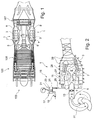
- Fig. 1 shows a gas turbine 100 comprising combustor assemblies 1 according to an embodiment of the present invention.
- Air entering the gas turbine at an intake 103 first flows through a cold section of the gas turbine in which vanes and blades of an axial compressor 105 compress the incoming air to an elevated pressure of approximately 2000 hPa - 40000 hPa depending on the type of the gas turbine.
- the compressed air then enters the combustion chambers 3 of the combustor assemblies 1 through air inlets 5.
- Fuel is continuously supplied to each combustion chamber 3 and is ignited within a flame region 7.
- the hot expanding exhaust gases from the combustion chamber 3 then exit through gas outlets 9 and finally flow through the turbine stage 107 before exiting the gas turbine.
- Fig. 2 shows details of an embodiment of a combustor assembly 1.
- a housing 11 encloses a combustion chamber 3.
- Incoming gas may enter the combustion chamber 3 through a gas inlet 5 and may then continuously flow through the combustion chamber 3 before exiting through a gas outlet 9.
- a fuel spray burner 13 adds fuel to the incoming air by spraying liquid or gaseous fuel into the incoming air stream which may then be ignited by an igniter (not shown).
- the fuel spray burner 13 and the igniter are part of a flame generator 6.
- the incoming fuel-enriched air then enters into a flame region 7 forming a primary combustion zone. In this flame region 7 the fuel-enriched air is combusted and releases its thermal energy.
- the gasflow then continues to flow towards the gas outlet and is exhausted.
- Typical velocity of the continuous gasflow from the gas inlet 5 to the gas outlet 9 is below Mach 0.4, i.e. is subsonic.
- the combustor assembly comprises a shock wave generator 15.
- the shock wave generator 15 comprises a quickly rotating piston compressor 17.
- the piston compressor 17 sucks incoming air through a gas inlet pipe 19 during an upward motion of a piston 21 within the cylinder 23.
- the air within the cylinder 23 is strongly compressed to an elevated pressure of for example by a factor of 2, preferably 5 higher than the average pressure in the combustor, for example to pressure values 10000 hPa - 150000 hPa depending on the gas turbine type.
- the compressed volume of the compressor 17 forms a pressure chamber 22.
- a valve 25 suddenly opens and releases the elevated pressure through gas pipes 26 which discharge into the combustion chamber 3 at a location distant to the flame region 7 and upstream thereof.
- the elevated pressure suddenly applied in a peripheral region of the combustion chamber 3 generates shock waves within the combustion chamber 3.
- the shock waves 27 are indicated by their respective shock wave front.
- the shock waves 27 propagate through the combustion chamber 3 in a direction towards the flame region 7. Due to a specific geometric shape of the combustion chamber 3, the shock waves 27 are deflected towards a centre of the combustion chamber 3 being at the same time a centre of the flame region 7.
- the shock waves may generate additional turbulences as described previously superimposing with turbulences generated by the fuel injection as indicated by the dashed line in the figure. Due to such generated turbulences, the fuel spray comprised in the incoming air is further mixed with the air. Furthermore, due to the abrupt pressure increase at a shock wave front, droplets of fuel within the incoming air may be further dispersed in case when liquid fuel is used.
- shock waves propagate through the combustion chamber 3 at supersonic velocities of for example Mach 1.3 relative to local thermodynamic conditions in the combustor, they may be at least partly reflected at portions of the housing 11 of the combustion chamber 3 or at the turbines blades and vanes behind the gas outlet 9.
- cold gas may be introduced into the combustion chamber by liner cooling inlets 28 arranged at a wall of the housing 11.
- the liner cooling inlets 28 may be provided with fluidic diodes 29.
- Such fluidic diodes 29 may have a helical shape like an extruder barrel and may have a specific impact on gas flowing through the fluidic diodes such that gas can flow in one direction without any significant flow resistance while in the opposite direction gas flow is mainly prevented due to an excessive flow resistance.
- the same principle can be used at the gas inlet 5 where supply air may flow through a fluidic diode 31 before entering the gas inlet 5 thereby attenuating backflow created by an enhanced pressure level and defracted and reflected shock waves.
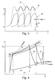
- Fig. 3 shows the time-dependency of the local pressure p(t) for a position within the combustion chamber 3, particularly for a location within the flame region 7.
- a wave front of a shock wave 27 including an abrupt pressure increase arrives at a time t 1 .
- the pressure increases from an initial pressure p 1 to an elevated pressure p 2 .
- This additional heat release is in-phase with the pressure increase effected by the shock wave and results in a temporary temperature rise. Due to the heat release rate increase being in-phase with the pressure increase, an additional pressure increase 33 occurs as a result of fulfilling the Rayleigh criterion.
- a multiplicity of shock wave s 27 is generated periodically one after another at a frequency of for example 1 kHz.
- the shock waves are generated at such high frequency and as each shock wave has a specific width and pressure profile, subsequent shock waves may overlap as shown in Fig. 3 .
- the resulting pressure profile 35 oscillates with the frequency of the generated pressure waves and is generally at higher pressure values than the pressure p 2 of the shock waves due to the combustion-induced pressure gain resulting in accordance with the Rayleigh-criterion.
- Fig. 4 shows a graph of the temperature T in dependence on the entropy S for a cyclic process 41 in a conventional combustor assembly and for a cyclic process 43 in a combustor assembly according to an embodiment of the present invention.
- the line including alternating dots and dashes represents an isobaric process at constant pressure whereas the dashed line represents an isochoric process at constant volume.
- the conventional cyclic process coming from point 3 to point 4 is approximately an isobaric process.
- the fact that the pressure is not completely constant may be due to pressure losses within the combustion chamber resulting for example from flow resistances.
- the cyclic process 43 within the combustor assembly comprises a certain pressure increase while going from point 3 to point 4'.
- this cyclic process is somewhere in between an isobaric and an isochoric process.
- the pressure increase is due to the described pressure gain as a result of fulfilling the Rayleigh-criterion.
- the cyclic process 43 occurring in the combustor assembly described herein results in a reduced entropy change ⁇ s' compared to the entropy change ⁇ s occurring in a conventional cyclic process 41.
- an additional enthalpy ⁇ h turbine may be used in the cyclic process 43 of the combustor assembly described herein. This additional enthalpy ⁇ h turbine represents an additional work that the system can provide to its surroundings.
- combustor assembly in accordance with an embodiment of the present invention, useful energy supply can be increased and energy losses due to irreversible processes during combustion are reduced. An overall increase in efficiency can be realized for a gas turbine using such combustor assembly.
Landscapes
- Engineering & Computer Science (AREA)
- Chemical & Material Sciences (AREA)
- Combustion & Propulsion (AREA)
- Mechanical Engineering (AREA)
- General Engineering & Computer Science (AREA)
Abstract
A combustor assembly and a gas turbine comprising such combustor assembly are proposed. The combustor assembly comprises a combustion chamber (1), a gas inlet (5) for providing gas to the combustion chamber (1), a gas outlet (9) for exhausting gas from the combustion chamber (3), a flame generator (6) for generating a flame in a flame region (7) within the combustion chamber (3) and a shock wave generator (15) for generating a propagating shock wave (27). The combustor assembly (3) is adapted such that the generated shock wave (27) propagates towards the flame region (7). Upon impact of the shock wave (27) in the flame region (7), a temporary increase in heat release rate may be obtained e.g. due to gas turbulences. Such increased heat release rate being in-phase with a pressure increase from the shock wave may result in fulfilling the Rayleigh-criterion thereby resulting in a total pressure gain within the combustion chamber (3). Due to such total pressure gain, the efficiency of the gas turbine may be increased substantially.
Description
- The present invention relates to a combustor assembly for combusting fuel within a combustion chamber. Furthermore, the invention relates to a gas turbine comprising such combustor assembly.
- In conventional gas turbines, combustion of a fuel takes place within a combustor assembly positioned between a compressor and a turbine. Oxygen-containing gas enters a combustion chamber at a gas inlet and continuously flows at a substantially stationary flow rate through the combustion chamber towards a gas outlet. Fuel is added to the incoming gas and is ignited and combusted within the combustion chamber.
- Such combustion chambers conventionally operate isobaric, i.e. the combustion is effected at an essentially constant pressure throughout the combustion process. However, a total pressure loss in the order of 3% to 4% usually occurs due to mixing losses or friction losses thereby contributing to a reduction of a thermal efficiency of the gas turbine.
- Generally, the efficiency of a gas turbine cycle is influenced by losses of each component of the gas turbine, i.e. the compressor, the combustor assembly and the turbine. Therein, the entropy is an indication of the losses generated in a thermodynamic system. The entropy is the portion of the energy content of a system which cannot be used for useful work and is therefore lost due to irreversible processes in the system.
- Conventional approaches to optimize power and efficiency of a gas turbine have been mainly directed to aerothermodynamically optimizing turbo components of the gas turbine, i.e. optimizing of the compressor and of the turbine.
- However, it has been observed by exergy analysis (exergy = portion of an energy content of a system which, in relation to a specific environmental condition, may be completely converted to useful work or, in other words, maximum work extraction possible during a thermodynamic process that brings the system into equilibrium with a heat reservoir) that, in an entire gas turbine cycle, the generated entropy corresponding to an exergy loss due to irreversible combustion in the combustion chamber contributes about 22% of overall losses in a gas turbine. Accordingly, such exergy loss contributes the largest portion to the overall losses in a gas turbine and is about 30 times higher than the losses in the high pressure turbine.
- Thermodynamic analysis of the gas turbine process shows that with a moderate pressure increase within the combustion chamber of 10 - 20%, an increase in the thermal gas turbine efficiency of up to 10% and correspondingly a reduction in the fuel consumption in the same order of magnitude may be obtained. Apparently, improving the efficiency of the combustor assembly within a gas turbine may substantially contribute to an optimization of the gas turbine with respect to its power and its efficiency.
- However, the combustion chamber has been mainly further developed in order to maintain and resist to higher combustion temperatures in order to thereby improve the efficiency of the gas turbine. Most modem gas turbines such as for example gas turbines used in aircraft still operate with an isobaric stationary combustion.
- In order to overcome disadvantages of such isobaric stationary combustion such as efficiency losses due to irreversible combustion, alternative approaches in fuel combustion and combustion technology for gas turbines have recently been investigated. Combustion chambers working with an (quasi-)isochoric combustion, wherein the gas is enclosed in a constant volume during combustion, have been developed. For example, combination engines comprising a gas turbine and a piston engine replacing the combustion chamber have been developed. Furthermore, pulse jet engines in which valves prevent the combustion gas of the ignited fuel mixture in the combustion chamber from exiting and disrupting intake air-flow have been developed.
- However, most of the above-mentioned approaches for realizing a pressure-increased combustion require complicated and heavy mechanical devices for generating the increased pressure. Therefore, engines comprising such combustion chambers operating at (quasi-) isochoric combustion cycles may be frequently subject to failure, may require increased maintenance efforts and, due to their increased weight, may not be suitable for aircraft. Furthermore, the optimization potential of many of such technical approaches seems to be already exploited at a high degree and seems to be mainly limited by the mechanical and thermal properties of available materials.
- There may be a need for a combustor assembly with an increased efficiency potential with regard to the thermal cycle efficiency of a gas turbine comprising such combustor assembly. Particularly, there may be a need for a combustor assembly generating a pressure rise between an inlet and an outlet.
- Furthermore, there may be a need for a gas turbine with an increased efficiency potential wherein such efficiency increase may be obtained by using a pressure-gain combustor assembly.
- Furthermore, there may be a need for a combustor assembly and a gas turbine with low weight and/or low complexity.
- At least some of the above-mentioned needs may be met with a combustor assembly and a gas turbine according to the appended independent claims. Advantageous embodiments are defined in the dependent claims.
- An important idea on which the present invention is based may be seen in the recognition that a pressure increase in a combustion chamber may be realized by interaction of shock waves or compression pulses with a flame burning in the combustion chamber. As will be described in more detail below, the energy needed for generating the shock waves may be less than the additional energy generated in the combustor assembly as a result of such combustion-induced pressure increase.
- Before describing details and advantages of the present invention and its embodiments further below with respect to the subject-matter as defined in the claims, principles of the invention may be described with a more general wording as follows:
- It may be seen as an aim of the present invention to generate a combustion-induced pressure increase within a combustion chamber as a result of an interaction between compression pulses induced by a shock wave propagating through the combustion chamber and a flame burning within this combustion chamber. The compression pulses may be for example generated by suddenly opening a valve between an additional compressor and the combustion chamber. Thereby, the highly compressed air from the compressor may abruptly propagate and spread throughout the combustion chamber thereby generating a shock wave front which moves through the combustion chamber with supersonic velocity. Thereby, the shock front may generate an abrupt or stepwise change of state wherein the fluid within the combustion chamber abruptly changes from a state before arrival of the shock wave to a state with e.g. higher pressure, higher temperature and higher density after arrival of the shock wave.
- The propagating shock waves are emitted in a direction towards a flame region of the combustion chamber in which the combustion of the injected fuel takes place. When the shock wave crosses the flame region, important effects may occur. These effects may be described with reference to the so-called Rayleigh-criterion. The Rayleigh-criterion teaches that an amplification of a pressure amplitude may be obtained when a periodical pressure oscillation and an oscillating heat release or enthalpy supply are superimposed in phase. In other words, if the periodic heat release is in phase with the pressure oscillation, the pressure oscillation will be amplified. This Rayleigh-criterion is known for more than 130 years and has been typically used to identify situations in which oscillatory combustion is promoted in order to, after such identification, suppress such unwanted oscillatory combustion. However, as to the inventors' knowledge, the physical effects on which the Rayleigh-criterion is based have never been used to generate a combustion-induced increase of the total pressure within a combustion chamber.
- When the shock wave impacts onto the flame region, a temporary increase in the heat release rate and in the flame temperature may occur due to the increased pressure and/or due to an increased mixing of fuel and air as a result of turbulences. As this temporary increase in flame temperature and heat release substantially coincides, i.e. is coupled in phase, with the pressure increase due to the crossing shock wave, the Rayleigh-criterion is fulfilled and thus a further amplification of the total pressure increase may be obtained. Furthermore, the shock wave may be further accelerated when entering the flame region with its elevated heat release rate. The increased pressure level of the gas together with the increased kinetic energy of the fluid flowing through the combustion chamber may result in an increase of the total pressure of the fluid at the outlet of the combustion chamber. In thermodynamic terms, this means that, although the temperature of the combustion gases at the outlet of the combustion chamber may be the same as in conventional combustion chambers, less energy is lost during the combustion due to a less irreversible energy conversion process. This may result in an overall increase of the efficiency of the gas turbine cycle.
- It shall be emphasized that using a controlled system of subsequent shock waves including compression pulses interacting with a stationary flame and thereby using the effects described by the Rayleigh-criterion in order to induce an additional amplification of the pressure level generated by the compression pulses is a completely different approach for increasing the efficiency of a gas turbine when compared with conventional approaches. While the temperature in the combustion chamber may not have to be increased compared to conventional approaches, a pressure gain may be obtained due to the in-phase-coupling of an increase in heat release and an increase in pressure level when a shock wave is passing across a flame region in the combustion chamber possibly leading to an improvement in thermal cycle efficiency of a gas turbine.
- It shall be noted that the increase in the total pressure is not simply a result of the shock waves propagating through the combustion chamber which themselves already induce a certain pressure increase. Instead, there is an additional pressure gain due to fulfilling the Rayleigh-criterion. It is mainly this additional gain in total pressure which provides an improvement of the combustor assembly when compared with conventional combustor assemblies. In other words, the achieved gas turbine efficiency gain due to combustor pressure-gain overcompensates the additional energy input necessary for generating the shock waves.
- According to an aspect of the present invention, a combustor assembly comprising a combustion chamber, a gas inlet for providing gas to the combustion chamber, a gas outlet for exhausting gas from the combustion chamber, a flame generator for generating a flame in a flame region within the combustion chamber and a shock wave generator for generating a propagating shock wave is proposed. Therein, the combustor assembly is adapted such that the generated shock wave propagates towards the flame region.
- With the exception of the provision of a shock wave generator, the combustor assembly may be provided with a combustion chamber having features of conventional combustion chambers as for example used in gas turbines for aircraft. For example, the combustion chamber may comprise a high-temperature resistant housing enclosing a combustion volume. At one end of the combustion chamber, oxygen-containing gas such as compressed ambient air may be provided to the combustion chamber via a gas inlet. The supplied gas may be enriched with a fuel in order to provide a highly flammable gas to the combustion chamber. Preferably, the fuel is injected into the incoming gas flow as a gas or in the form of dispersed liquid droplets. While the gas enters the combustion chamber usually with a substantial velocity as it comes for example from the compressor of a gas turbine using the combustor assembly, the continuous gas flow from the gas inlet to the gas outlet will occur at subsonic velocities. At the gas outlet, the gas flow may be exhausted from the combustion chamber and may then enter for example a turbine stage of an enclosing gas turbine.
- The fuel- and oxygen-containing combustion gas may be ignited within the combustion chamber and may then combust within a flame region. Without shock wave s crossing the flame region, the flame region would be generally stationary, i.e. the position and the extension of the flame region remain constant throughout a stationary operation of the combustor assembly. However, due to impacting shock wave s, the flame region may move or oscillate within the combustion chamber, as will be described in more detail further below. However, although the position and the extension of the flame region may change upon impact of a shock wave, the combustion within the flame region will never be completely interrupted during normal operation, i.e. the combustion is at least quasi-stationary.
- In other words, a continuous gas flow flows through the combustion chamber from the gas inlet to the gas outlet and combustion is continuously taking place within the flame region. Such continuous combustion may also be referred to as "deflagration". Deflagration is a technical term describing subsonic combustion that usually propagates through thermal conductivity, i.e. hot burning material heats the next layer of cold material and ignites it. Deflagration may occur in laminar or turbulent gas flows. The velocity of a flame in deflagration may range between approximately 50 m/s up to the speed of sound which itself locally depends on several parameters such as local pressure, local temperature, etc. The contrary to deflagration is detonation which is a process of combustion in which a supersonic shock wave is propagated through a fluid due to an energy release in a reaction zone. Usually, in a detonation, gas may be compressed to a very high pressure and temperature and then propagates as a shock wave with a velocity much higher than the speed of sound, e.g. with a velocity of
Mach 3. Accordingly, in the combustor assembly proposed herein, normal deflagration may occur within the flame region as long as no shock waves propagate through the flame region. When a shock wave crosses the flame region, the local gas pressure as well as the current gas velocity may temporarily increase. Particularly, the temporary gas velocity may exceed the speed of sound during the short duration the shock wave needs to cross the flame region. Thereby, the combusting gases within the flame region may be temporarily entrained and the flame region may be temporarily displaced in a direction towards the gas outlet of the combustion chamber. After the shock wave has crossed the flame region, the flame region may return towards its original location corresponding to the normal deflagration position. In case shock waves are generated periodically and therefore cross the flame region periodically, the flame region may oscillate within the combustion chamber at a frequency corresponding to the frequency of shock wave generation. - The shock wave generator being a characteristic feature of the proposed combustor assembly is adapted for generating a propagating shock wave. A shock wave, sometimes also referred to as "shock front" or simply "shock", is a type of propagating disturbance. Like an ordinary wave, it carries energy and may propagate through a medium, either solid, liquid or gas. Shock waves are characterized by an abrupt, nearly discontinuous change in characteristics of the medium. Across a shock there is always an extreme rise in pressure, temperature and/or density of the medium or the flow of the medium. Contrary to a normal subsonic sound wave, a shock wave travels through a medium at a speed which is higher than the speed of an ordinary wave, i.e. higher than the speed of sound at the respective local conditions which may depend on the local temperature, pressure, medium properties, etc. When an object or disturbance moves faster than the information about it can be propagated through the surrounding fluid, fluid near the disturbance cannot react or "get out of the way" before the disturbance arrives. In shock waves, the properties of the fluid such as density, pressure, temperature, velocity, Mach number, etc. may change almost instantaneously. In other words, these parameters do not change their values continuously for example with a sinusoidal behaviour but very abruptly. Measurements of the thickness of shock waves have resulted in values approximately one order of magnitude greater than a mean free path of the gas investigated, roughly micrometers at atmospheric conditions.
- Due to the sudden occurrence the propagating shock wave when reaching the flame region, the gas within the flame region cannot simply "escape" by accelerating a laminar gas flow. Instead, a turbulent gas flow may be induced in the flame region by the crossing shock wave. Such turbulences may improve the mixing of fuel with oxygen-containing gas and may thereby result in a temporary temperature rise in the flame region. Furthermore, in case a liquid fuel is injected to the flame region in the form of droplets, such droplets may burst upon impact of a shock wave such that a distribution of the fuel within the flame region may be improved thereby again resulting in a temporary temperature rise.
- Furthermore, the effected increase in heat release rate within the flame region may be influenced by parameters of the generated shock waves such as a location of generation of the shock waves within the combustion chamber, a magnitude of the temporary pressure increase generated by a propagating shock wave, a geometry of a wave front of the shock wave and a direction of the shock wave with respect to the flame region, for example. Such parameters may be influenced by the geometry of the combustion chamber, the material used for the walls of the combustion chamber and influencing reflection properties of these walls, the geometries of the gas inlet and the gas outlet of the combustion chamber, the way of mixing fuel into incoming gas, the kind of gas flow through the combustion chamber, laminar or turbulent, etc., for example.
- Advantageously, the shock wave generator is adapted for generating shock waves propagating towards the flame region at velocities between
Mach 1 andMach 3, preferably betweenMach 1 andMach 2 and more preferably betweenMach 1 and Mach 1.4 relative to local thermodynamic condition in the combustor. The pressure and temperature rise generated by the shock wave may be a function of the Mach number of the shock and of the thermodynamic conditions of the fluid prior to the shock. The local Mach number of the shock may depend on the fluid composition, the thermodynamic condition and the flow of the fluid. - Advantageously, the shock wave generator is adapted for generating a local temporary pressure increase of at least 5%, preferably at least 100%. In other words, a local pressure at a position within the combustion chamber may increase about at least 5% - 100% upon impact of the shock wave when compared to the local pressure before impact of the shock wave. At normal operating conditions of a gas turbine, i.e. prior to occurrence of shock waves, gas is provided by the compressor of the gas turbine to the combustor assembly at pressure levels of typically between 2000 to 40000 hPa. Experiments have shown that shock waves which temporarily more than double the local pressure, i.e. a local temporary pressure increase of more than 100%, may result, by interacting with a flame, in a significant increase of the total pressure within the combustor assembly.
- Advantageously, the shock wave generator is adapted for periodically generating a propagating shock wave within the combustion chamber. For example, shock waves may be generated at a frequency in a range of between 10 Hz and 5000 Hz or higher, preferably between 20 Hz and 2000 Hz and more preferably between 40 and 1000 Hz. By periodically generating a propagating shock wave, the process of combustion-induced total pressure gain may be periodically repeated. Generally, the higher the frequency of shock wave generation, i.e. the higher the ratio of the duration, in which a shock wave propagates through a flame region with respect to a duration in which no shock wave travels through a flame region, the stronger the effect of combustion-induced total pressure gain. An upper limit of the frequency may be given by the velocity with which the shock wave generator may be "reloaded" for generating the next shock wave.
- For example, the shock wave generator may comprise a pressure chamber and a valve at an interface between the pressure chamber and the combustion chamber. Gas may be continuously replenished to the pressure chamber and a pressure level within the pressure chamber may be retained well above the pressure level within the combustion chamber and may be for example two times, preferably five times the pressure level within the combustion chamber. The valve may be adapted to be abruptly opened in order to allow gas exchange between the pressure chamber and the neighbouring combustion chamber. Thus, upon quickly opening of the valve, a shock wave may be generated and then propagate through the combustion chamber.
- Advantageously, the shock wave generator comprises a compressor. This compressor may be used for providing highly compressed air to the pressure chamber. In an advantageous embodiment, the shock wave generator comprises a rapidly moving piston compressor. This piston compressor may periodically compress supplied air to a high compression level and then release the compressed air preferably at the time of highest compression towards the combustion chamber thereby generating a shock wave.
- Advantageously, the shock wave generator is located at a distance to the flame region. In other words, the shock wave generator is not located directly adjacent to the flame region and particularly, the shock wave generator does not directly contact the flame region. Such positioning of the shock wave generator distant from the flame region is possible in the proposed combustor assembly as the shock wave generator does not need to be adapted for generating an overall pressure increase throughout the entire combustion chamber. In other words, the shock wave generator does not need to increase the static pressure within the combustion chamber, but instead the shock wave generator is adapted to generate propagating shock wave s wherein such propagating shock waves can be generated at a distance to the flame region where they finally shall effectively act. For example, the shock wave generator may be located several centimetres away from the flame region. Accordingly, the shock wave generator and in particular the parts of the shock wave generator which are in direct contact to the combustion chamber's inner volume do not have to be highly temperature resistant.
- Advantageously, the shock wave generator is located at a position upstream of the flame region. Herein, the term "upstream" relates to a flow direction of gas entering the combustion chamber at the gas inlet and exiting the combustion chamber at the gas outlet. While gas downstream of the flame region, i.e. during or after combustion, may be at very high temperatures, the gas entering the combustion chamber and being upstream of the flame region is usually not at very high temperatures. Accordingly, positioning the shock wave generator at such upstream position may further release the heat resistance requirements for the shock wave generator.
- According to a further aspect of the present invention, a gas turbine comprising a combustor assembly as described further above is proposed.
- A gas turbine, which is also called a combustion turbine, is a rotary engine that extracts energy from a flow of combustion gas. It usually has an upstream compressor coupled to a downstream turbine and a combustion chamber in between.
- As discussed further above, an important portion of the overall efficiency losses in a gas turbine are caused within the combustor assembly. Accordingly, using an improved combustor assembly generating a combustion induced pressure-rise as described further above, may provide for a significant efficiency increase of the entire gas turbine. With the combustor assembly as proposed, a combustion-induced total pressure gain over the combustion chamber of about 10 - 20% may be realized. Upon optimization of respective turbo components of the turbine and the compressor, an efficiency increase of the entire gas turbine of up to 20% seems to be possible. This is an enormous potential for improvement which seems to beyond any other currently known approach for optimizing gas turbines. Furthermore, using the proposed combustor assembly, harmful substances in the exhausted gas may be significantly reduced. On the one hand, this may result from a reduction of fuel consumption, on the other hand, the residence time in the hot flame region is shortened thereby significantly reducing the generation of nitrogen oxides (NOx).
- It has to be noted that aspects and embodiments as well as features and advantages of the present invention are described herein with reference to different subject-matters. In particular, some embodiments have been described with reference to the proposed combustor assembly whereas other embodiments have been described with reference to the proposed gas turbine or to a mode of operating the combustor assembly. However, a person skilled in the art will gather from the above and the following description that, unless other notified, in addition to any combination of features belonging to one type of subject-matter also any combination between features relating to different subject-matters is considered to be disclosed with this application.
- Features and advantages of the present invention will be further described with respect to specific embodiments as shown in the accompanying figures but to which the invention shall not be limited.
-
Fig. 1 shows a gas turbine comprising a combustor assembly according to an embodiment of the present invention. -
Fig. 2 shows details of a combustor assembly according to an embodiment of the present invention. -
Fig. 3 shows a graph illustrating the time-dependent pressure at a location within the combustion chamber according to an embodiment of the present invention. -
Fig. 4 shows a graph illustrating diagrams of cyclic processes within a conventional combustor assembly in comparison with those of a combustor assembly according to an embodiment of the present invention. - All drawings are schematically and not to scale. Same reference signs relate to same or corresponding features.
-
Fig. 1 shows agas turbine 100 comprisingcombustor assemblies 1 according to an embodiment of the present invention. Air entering the gas turbine at anintake 103 first flows through a cold section of the gas turbine in which vanes and blades of anaxial compressor 105 compress the incoming air to an elevated pressure of approximately 2000 hPa - 40000 hPa depending on the type of the gas turbine. The compressed air then enters thecombustion chambers 3 of thecombustor assemblies 1 throughair inlets 5. Fuel is continuously supplied to eachcombustion chamber 3 and is ignited within aflame region 7. The hot expanding exhaust gases from thecombustion chamber 3 then exit throughgas outlets 9 and finally flow through theturbine stage 107 before exiting the gas turbine. -
Fig. 2 shows details of an embodiment of acombustor assembly 1. Ahousing 11 encloses acombustion chamber 3. Incoming gas may enter thecombustion chamber 3 through agas inlet 5 and may then continuously flow through thecombustion chamber 3 before exiting through agas outlet 9. Afuel spray burner 13 adds fuel to the incoming air by spraying liquid or gaseous fuel into the incoming air stream which may then be ignited by an igniter (not shown). Thefuel spray burner 13 and the igniter are part of aflame generator 6. The incoming fuel-enriched air then enters into aflame region 7 forming a primary combustion zone. In thisflame region 7 the fuel-enriched air is combusted and releases its thermal energy. The gasflow then continues to flow towards the gas outlet and is exhausted. Typical velocity of the continuous gasflow from thegas inlet 5 to thegas outlet 9 is below Mach 0.4, i.e. is subsonic. - Furthermore, the combustor assembly comprises a
shock wave generator 15. Theshock wave generator 15 comprises a quickly rotatingpiston compressor 17. Thepiston compressor 17 sucks incoming air through agas inlet pipe 19 during an upward motion of apiston 21 within thecylinder 23. In a subsequent downward motion of thepiston 21, the air within thecylinder 23 is strongly compressed to an elevated pressure of for example by a factor of 2, preferably 5 higher than the average pressure in the combustor, for example to pressure values 10000 hPa - 150000 hPa depending on the gas turbine type. Thereby, the compressed volume of thecompressor 17 forms apressure chamber 22. At the moment of maximum pressure, avalve 25 suddenly opens and releases the elevated pressure throughgas pipes 26 which discharge into thecombustion chamber 3 at a location distant to theflame region 7 and upstream thereof. The elevated pressure suddenly applied in a peripheral region of thecombustion chamber 3 generates shock waves within thecombustion chamber 3. - In the figure, the
shock waves 27 are indicated by their respective shock wave front. Theshock waves 27 propagate through thecombustion chamber 3 in a direction towards theflame region 7. Due to a specific geometric shape of thecombustion chamber 3, theshock waves 27 are deflected towards a centre of thecombustion chamber 3 being at the same time a centre of theflame region 7. There, within theflame region 7, the shock waves may generate additional turbulences as described previously superimposing with turbulences generated by the fuel injection as indicated by the dashed line in the figure. Due to such generated turbulences, the fuel spray comprised in the incoming air is further mixed with the air. Furthermore, due to the abrupt pressure increase at a shock wave front, droplets of fuel within the incoming air may be further dispersed in case when liquid fuel is used. These effects may result in a temporary temperature rise and increased heat release rate within theflame region 7. The temperature rise coincides with the pressure rise due to the shock waves. In other words, the rise in heat release rate is in-phase with the pressure rise. Due to this fact, the Rayleigh criterion is fulfilled and a further additional gain in the pressure within thecombustion chamber 3 may be obtained. - While the shock waves propagate through the
combustion chamber 3 at supersonic velocities of for example Mach 1.3 relative to local thermodynamic conditions in the combustor, they may be at least partly reflected at portions of thehousing 11 of thecombustion chamber 3 or at the turbines blades and vanes behind thegas outlet 9. - In order to cool a lining inner portion of the
housing 11, cold gas may be introduced into the combustion chamber byliner cooling inlets 28 arranged at a wall of thehousing 11. In order to reduce gas backflow through theliner cooling inlets 28 due to reflected shock waves or due to the increased total pressure within thecombustion chamber 3, theliner cooling inlets 28 may be provided withfluidic diodes 29. Suchfluidic diodes 29 may have a helical shape like an extruder barrel and may have a specific impact on gas flowing through the fluidic diodes such that gas can flow in one direction without any significant flow resistance while in the opposite direction gas flow is mainly prevented due to an excessive flow resistance. The same principle can be used at thegas inlet 5 where supply air may flow through afluidic diode 31 before entering thegas inlet 5 thereby attenuating backflow created by an enhanced pressure level and defracted and reflected shock waves. -
Fig. 3 shows the time-dependency of the local pressure p(t) for a position within thecombustion chamber 3, particularly for a location within theflame region 7. At this position, a wave front of ashock wave 27 including an abrupt pressure increase arrives at a time t1. Upon arrival of the shock wave propagating with a velocity of more thanMach 1, the pressure increases from an initial pressure p1 to an elevated pressure p2. A short period Δt of for example approximately 0.00001s (= 10µs) after the arrival of the shock wave front, an increased heat releaseoccurs. This additional heat release is in-phase with the pressure increase effected by the shock wave and results in a temporary temperature rise. Due to the heat release rate increase being in-phase with the pressure increase, an
additional pressure increase 33 occurs as a result of fulfilling the Rayleigh criterion. - As shown in
Fig. 3 , a multiplicity of shock wave s 27 is generated periodically one after another at a frequency of for example 1 kHz. As the shock waves are generated at such high frequency and as each shock wave has a specific width and pressure profile, subsequent shock waves may overlap as shown inFig. 3 . Accordingly, the resultingpressure profile 35 oscillates with the frequency of the generated pressure waves and is generally at higher pressure values than the pressure p2 of the shock waves due to the combustion-induced pressure gain resulting in accordance with the Rayleigh-criterion. -
Fig. 4 shows a graph of the temperature T in dependence on the entropy S for acyclic process 41 in a conventional combustor assembly and for acyclic process 43 in a combustor assembly according to an embodiment of the present invention. The line including alternating dots and dashes represents an isobaric process at constant pressure whereas the dashed line represents an isochoric process at constant volume. - As can be clearly seen in
Fig. 4 , the conventional cyclic process coming frompoint 3 topoint 4 is approximately an isobaric process. The fact that the pressure is not completely constant may be due to pressure losses within the combustion chamber resulting for example from flow resistances. - In contrast hereto, the
cyclic process 43 within the combustor assembly according to an embodiment of the present invention comprises a certain pressure increase while going frompoint 3 to point 4'. In other words, this cyclic process is somewhere in between an isobaric and an isochoric process. The pressure increase is due to the described pressure gain as a result of fulfilling the Rayleigh-criterion. - As can be seen from
Fig. 4 , thecyclic process 43 occurring in the combustor assembly described herein results in a reduced entropy change Δs' compared to the entropy change Δs occurring in a conventionalcyclic process 41. On the other hand, due to such reduced losses resulting from reduced entropy changes, an additional enthalpy Δhturbine may be used in thecyclic process 43 of the combustor assembly described herein. This additional enthalpy Δhturbine represents an additional work that the system can provide to its surroundings. - Accordingly, with the combustor assembly in accordance with an embodiment of the present invention, useful energy supply can be increased and energy losses due to irreversible processes during combustion are reduced. An overall increase in efficiency can be realized for a gas turbine using such combustor assembly.
- It should be noted that the term "comprising" does not exclude other elements or steps and that the indefinite article "a" or "an" does not exclude the plural. Also elements described in association with different embodiments may be combined. It should also be noted that reference signs in the claims shall not be construed as limiting the scope of the claims.
-
- 1
- Combustor assembly
- 3
- Combustion chamber
- 5
- Gas inlet
- 6
- Flame generator
- 7
- Flame region
- 9
- Gas outlet
- 11
- Housing
- 13
- Fuel spray burner
- 15
- Shock wave generator
- 17
- Piston compressor
- 19
- Gas inlet pipe
- 21
- Piston
- 22
- Pressure chamber
- 23
- Cylinder
- 25
- Valve
- 26
- Gas pipe
- 27
- Shock wave
- 28
- Liner cooling inlet
- 29
- Fluidic diode for liner cooling
- 31
- Fluidic diode for gas inlet
- 33
- Pressure gain due to Rayleigh-criterion
- 35
- Resulting pressure profile
- 41
- Conventional cyclic process
- 43
- Cyclic process of proposed combustor assembly
- 100
- Gas turbine
- 103
- Air intake
- 105
- Compressor
- 107
- Turbine
Claims (14)
- A combustor assembly (1) comprising:a combustion chamber (3);a gas inlet (5) for providing gas to the combustion chamber;a gas outlet (9) for exhausting gas from the combustion chamber;a flame generator (6) for generating a flame in a flame region (7) within the combustion chamber; anda shock wave generator (15) for generating a propagating shock wave (27);wherein the combustor assembly is adapted such that the generated shock wave propagates towards the flame region.
- The combustor assembly according to claim 1, wherein the combustor assembly (3) is adapted for establishing a continuous gas flow from the gas inlet (5) to the gas outlet (9) wherein a gas pressure within the gas flow may be temporarily increased by shock wave (27) propagating through the gas flow.
- The combustor assembly according to claim 1 or 2, wherein the combustor assembly (1) is adapted such that the shock wave (27) generated by the shock wave generator (15) induces an increase in heat release rate in the flame region (7) when the shock wave travels through the flame region.
- The combustor assembly according to claim 3, wherein the increase in heat release rate is induced by gas turbulences and elevated pressure and temperature generated by the shock wave (27) passing through the flame region (7).
- The combustor assembly according to one of claims 1 to 4, wherein the shock wave generator (15) is adapted for generating propagating shock waves at velocities between Mach 1 and Mach 3 relative to local thermodynamic condition in the combustor.
- The combustor assembly according to one of claims 1 to 5, wherein the shock wave generator (15) is adapted for generating a local temporary pressure increase of at least 1000hPa.
- The combustor assembly according to one of claims 1 to 6, wherein the shock wave generator (15) is adapted for periodically generating a propagating shock wave (27).
- The combustor assembly according to claim 7, wherein the shock wave generator (15) is adapted for periodically generating a propagating shock wave (27) at a frequency in a range between 10 Hz and 5000 Hz.
- The combustor assembly according to one of claims 1 to 8, wherein the shock wave generator (15) comprises a pressure chamber (22) and a valve (25) at an interface between the pressure chamber (22) and the combustion chamber (3).
- The combustor assembly according to one of claims 1 to 9, wherein the shock wave generator (15) comprises a compressor (17).
- The combustor assembly according to claim 10, wherein the shock wave generator (15) comprises a rapidly moving piston compressor (17).
- The combustor assembly according to one of claims 1 to 11, wherein the shock wave generator (15) is located at a distance to the flame region (7).
- The combustor assembly according to one of claims 1 to 12, wherein the shock wave generator (15) is located at a position upstream of the flame region (7).
- A gas turbine (100) comprising a combustor assembly (1) according to one of claims 1 to 13.
Priority Applications (1)
| Application Number | Priority Date | Filing Date | Title |
|---|---|---|---|
| EP09162306A EP2261559A1 (en) | 2009-06-09 | 2009-06-09 | Combustor assembly for gas turbine with combustion-induced total pressure gain |
Applications Claiming Priority (1)
| Application Number | Priority Date | Filing Date | Title |
|---|---|---|---|
| EP09162306A EP2261559A1 (en) | 2009-06-09 | 2009-06-09 | Combustor assembly for gas turbine with combustion-induced total pressure gain |
Publications (1)
| Publication Number | Publication Date |
|---|---|
| EP2261559A1 true EP2261559A1 (en) | 2010-12-15 |
Family
ID=41258487
Family Applications (1)
| Application Number | Title | Priority Date | Filing Date |
|---|---|---|---|
| EP09162306A Withdrawn EP2261559A1 (en) | 2009-06-09 | 2009-06-09 | Combustor assembly for gas turbine with combustion-induced total pressure gain |
Country Status (1)
| Country | Link |
|---|---|
| EP (1) | EP2261559A1 (en) |
Cited By (5)
| Publication number | Priority date | Publication date | Assignee | Title |
|---|---|---|---|---|
| WO2016061654A1 (en) * | 2014-10-21 | 2016-04-28 | Bonagura Paulo Sergio | Combustor with pressure gain, intermittent combustion and substantially continuous discharge flow |
| US10436110B2 (en) | 2017-03-27 | 2019-10-08 | United Technologies Corporation | Rotating detonation engine upstream wave arrestor |
| US20200063968A1 (en) * | 2017-04-06 | 2020-02-27 | University Of Cincinnati | Rotating detonation engines and related devices and methods |
| US10627111B2 (en) | 2017-03-27 | 2020-04-21 | United Technologies Coproration | Rotating detonation engine multi-stage mixer |
| US11149954B2 (en) * | 2017-10-27 | 2021-10-19 | General Electric Company | Multi-can annular rotating detonation combustor |
Citations (5)
| Publication number | Priority date | Publication date | Assignee | Title |
|---|---|---|---|---|
| FR1105024A (en) * | 1953-05-23 | 1955-11-25 | Babcock & Wilcox France | Method and device for accelerating combustions using longitudinal vibrations |
| GB838326A (en) * | 1956-12-03 | 1960-06-22 | Andre Johannes Meyer | Method and means for control of combustion in internal combustion engines |
| GB858601A (en) * | 1958-02-22 | 1961-01-11 | Rolls Royce | Improved gas generator and method for generating combustion gas under pressure |
| DE2209034A1 (en) * | 1972-02-25 | 1973-09-06 | Inst Politehnic | PROCEDURES AND BURNERS TO ENHANCE THE COMBUSTION PROCESS |
| DE3626356A1 (en) * | 1986-08-04 | 1988-05-05 | Guenter J Britz | Method for increasing the gas dynamics and pollutant gas elimination by additive interactions on elemental particles and electric charges for optimising molecular and atomic transition probability in internal combustion engines (isobaric processes)... |
-
2009
- 2009-06-09 EP EP09162306A patent/EP2261559A1/en not_active Withdrawn
Patent Citations (5)
| Publication number | Priority date | Publication date | Assignee | Title |
|---|---|---|---|---|
| FR1105024A (en) * | 1953-05-23 | 1955-11-25 | Babcock & Wilcox France | Method and device for accelerating combustions using longitudinal vibrations |
| GB838326A (en) * | 1956-12-03 | 1960-06-22 | Andre Johannes Meyer | Method and means for control of combustion in internal combustion engines |
| GB858601A (en) * | 1958-02-22 | 1961-01-11 | Rolls Royce | Improved gas generator and method for generating combustion gas under pressure |
| DE2209034A1 (en) * | 1972-02-25 | 1973-09-06 | Inst Politehnic | PROCEDURES AND BURNERS TO ENHANCE THE COMBUSTION PROCESS |
| DE3626356A1 (en) * | 1986-08-04 | 1988-05-05 | Guenter J Britz | Method for increasing the gas dynamics and pollutant gas elimination by additive interactions on elemental particles and electric charges for optimising molecular and atomic transition probability in internal combustion engines (isobaric processes)... |
Cited By (7)
| Publication number | Priority date | Publication date | Assignee | Title |
|---|---|---|---|---|
| WO2016061654A1 (en) * | 2014-10-21 | 2016-04-28 | Bonagura Paulo Sergio | Combustor with pressure gain, intermittent combustion and substantially continuous discharge flow |
| US10436110B2 (en) | 2017-03-27 | 2019-10-08 | United Technologies Corporation | Rotating detonation engine upstream wave arrestor |
| US10627111B2 (en) | 2017-03-27 | 2020-04-21 | United Technologies Coproration | Rotating detonation engine multi-stage mixer |
| US20200063968A1 (en) * | 2017-04-06 | 2020-02-27 | University Of Cincinnati | Rotating detonation engines and related devices and methods |
| US11761635B2 (en) * | 2017-04-06 | 2023-09-19 | University Of Cincinnati | Rotating detonation engines and related devices and methods |
| US12618565B2 (en) | 2017-04-06 | 2026-05-05 | University Of Cincinnati | Rotating detonation engines and related devices and methods |
| US11149954B2 (en) * | 2017-10-27 | 2021-10-19 | General Electric Company | Multi-can annular rotating detonation combustor |
Similar Documents
| Publication | Publication Date | Title |
|---|---|---|
| US8683780B2 (en) | Gas turbine engine and pulse detonation combustion system | |
| Nishida et al. | Analysis of entropy generation and exergy loss during combustion | |
| RU2660734C2 (en) | Pressure-gain combustion chamber (versions) and operating method thereof | |
| EP2559939A2 (en) | Pulse detonation combustor with plenum | |
| US20140238026A1 (en) | Fuel nozzle for reducing modal coupling of combustion dynamics | |
| CN108869046B (en) | Combustor, gas turbine, and method for distributing compressed air of combustor | |
| CA2386916A1 (en) | Steam injection nozzle design of gas turbine combustion liners for enhancing power output and efficiency | |
| US6571549B1 (en) | Jet noise suppressor | |
| US20080063514A1 (en) | Seal system for an interturbine duct within a gas turbine engine | |
| RU2739659C2 (en) | Sound-absorbing nozzle (versions) | |
| Wang et al. | Back-propagation suppression study based on intake configuration optimization for an air-breathing pulse detonation engine | |
| KR102915025B1 (en) | rotary internal combustion engine | |
| US20100037622A1 (en) | Contoured Impingement Sleeve Holes | |
| KR20190048055A (en) | Combustor and gas turbine comprising the same | |
| US11280270B2 (en) | Igniter assembly for a gas turbine combustor | |
| RU2623592C1 (en) | Rotary gas turbine engine | |
| CN218820517U (en) | Double-working-medium combustion chamber and gas turbine | |
| KR102661014B1 (en) | Duct assembly and combustor including the same | |
| KR102583225B1 (en) | Micromixer and gas turbine comprising the same | |
| CN115682031B (en) | Dual-medium combustion chamber and gas turbine | |
| CN116202105B (en) | Swirl combustion chamber head structure for optimizing combustion performance | |
| Sob et al. | Modelling and designing of a turbofan engine with more enhanced overall engine efficiency during operation | |
| KR101877675B1 (en) | A transition piece assembly and a combustor and a gas turbine including the same | |
| Kentfield et al. | Further development of an improved pulse, pressure gain, gas-turbine combustor | |
| Gemmen et al. | Achieving improved cycle efficiency via pressure gain combustors |
Legal Events
| Date | Code | Title | Description |
|---|---|---|---|
| PUAI | Public reference made under article 153(3) epc to a published international application that has entered the european phase |
Free format text: ORIGINAL CODE: 0009012 |
|
| AK | Designated contracting states |
Kind code of ref document: A1 Designated state(s): AT BE BG CH CY CZ DE DK EE ES FI FR GB GR HR HU IE IS IT LI LT LU LV MC MK MT NL NO PL PT RO SE SI SK TR |
|
| AX | Request for extension of the european patent |
Extension state: AL BA RS |
|
| 17P | Request for examination filed |
Effective date: 20110530 |
|
| 17Q | First examination report despatched |
Effective date: 20120514 |
|
| STAA | Information on the status of an ep patent application or granted ep patent |
Free format text: STATUS: THE APPLICATION IS DEEMED TO BE WITHDRAWN |
|
| 18D | Application deemed to be withdrawn |
Effective date: 20120925 |