EP2261487A1 - Gas turbine controller - Google Patents
Gas turbine controller Download PDFInfo
- Publication number
- EP2261487A1 EP2261487A1 EP20090828896 EP09828896A EP2261487A1 EP 2261487 A1 EP2261487 A1 EP 2261487A1 EP 20090828896 EP20090828896 EP 20090828896 EP 09828896 A EP09828896 A EP 09828896A EP 2261487 A1 EP2261487 A1 EP 2261487A1
- Authority
- EP
- European Patent Office
- Prior art keywords
- flow rate
- fuel
- fuel flow
- function generator
- value
- Prior art date
- Legal status (The legal status is an assumption and is not a legal conclusion. Google has not performed a legal analysis and makes no representation as to the accuracy of the status listed.)
- Granted
Links
Images


Classifications
-
- F—MECHANICAL ENGINEERING; LIGHTING; HEATING; WEAPONS; BLASTING
- F02—COMBUSTION ENGINES; HOT-GAS OR COMBUSTION-PRODUCT ENGINE PLANTS
- F02C—GAS-TURBINE PLANTS; AIR INTAKES FOR JET-PROPULSION PLANTS; CONTROLLING FUEL SUPPLY IN AIR-BREATHING JET-PROPULSION PLANTS
- F02C9/00—Controlling gas-turbine plants; Controlling fuel supply in air- breathing jet-propulsion plants
- F02C9/16—Control of working fluid flow
- F02C9/18—Control of working fluid flow by bleeding, bypassing or acting on variable working fluid interconnections between turbines or compressors or their stages
-
- F—MECHANICAL ENGINEERING; LIGHTING; HEATING; WEAPONS; BLASTING
- F01—MACHINES OR ENGINES IN GENERAL; ENGINE PLANTS IN GENERAL; STEAM ENGINES
- F01D—NON-POSITIVE DISPLACEMENT MACHINES OR ENGINES, e.g. STEAM TURBINES
- F01D17/00—Regulating or controlling by varying flow
- F01D17/02—Arrangement of sensing elements
- F01D17/04—Arrangement of sensing elements responsive to load
-
- F—MECHANICAL ENGINEERING; LIGHTING; HEATING; WEAPONS; BLASTING
- F01—MACHINES OR ENGINES IN GENERAL; ENGINE PLANTS IN GENERAL; STEAM ENGINES
- F01D—NON-POSITIVE DISPLACEMENT MACHINES OR ENGINES, e.g. STEAM TURBINES
- F01D17/00—Regulating or controlling by varying flow
- F01D17/02—Arrangement of sensing elements
- F01D17/08—Arrangement of sensing elements responsive to condition of working-fluid, e.g. pressure
- F01D17/085—Arrangement of sensing elements responsive to condition of working-fluid, e.g. pressure to temperature
-
- F—MECHANICAL ENGINEERING; LIGHTING; HEATING; WEAPONS; BLASTING
- F02—COMBUSTION ENGINES; HOT-GAS OR COMBUSTION-PRODUCT ENGINE PLANTS
- F02C—GAS-TURBINE PLANTS; AIR INTAKES FOR JET-PROPULSION PLANTS; CONTROLLING FUEL SUPPLY IN AIR-BREATHING JET-PROPULSION PLANTS
- F02C9/00—Controlling gas-turbine plants; Controlling fuel supply in air- breathing jet-propulsion plants
- F02C9/16—Control of working fluid flow
- F02C9/20—Control of working fluid flow by throttling; by adjusting vanes
- F02C9/22—Control of working fluid flow by throttling; by adjusting vanes by adjusting turbine vanes
-
- F—MECHANICAL ENGINEERING; LIGHTING; HEATING; WEAPONS; BLASTING
- F02—COMBUSTION ENGINES; HOT-GAS OR COMBUSTION-PRODUCT ENGINE PLANTS
- F02C—GAS-TURBINE PLANTS; AIR INTAKES FOR JET-PROPULSION PLANTS; CONTROLLING FUEL SUPPLY IN AIR-BREATHING JET-PROPULSION PLANTS
- F02C9/00—Controlling gas-turbine plants; Controlling fuel supply in air- breathing jet-propulsion plants
- F02C9/26—Control of fuel supply
- F02C9/28—Regulating systems responsive to plant or ambient parameters, e.g. temperature, pressure, rotor speed
-
- F—MECHANICAL ENGINEERING; LIGHTING; HEATING; WEAPONS; BLASTING
- F02—COMBUSTION ENGINES; HOT-GAS OR COMBUSTION-PRODUCT ENGINE PLANTS
- F02C—GAS-TURBINE PLANTS; AIR INTAKES FOR JET-PROPULSION PLANTS; CONTROLLING FUEL SUPPLY IN AIR-BREATHING JET-PROPULSION PLANTS
- F02C9/00—Controlling gas-turbine plants; Controlling fuel supply in air- breathing jet-propulsion plants
- F02C9/48—Control of fuel supply conjointly with another control of the plant
- F02C9/50—Control of fuel supply conjointly with another control of the plant with control of working fluid flow
- F02C9/52—Control of fuel supply conjointly with another control of the plant with control of working fluid flow by bleeding or by-passing the working fluid
-
- F—MECHANICAL ENGINEERING; LIGHTING; HEATING; WEAPONS; BLASTING
- F02—COMBUSTION ENGINES; HOT-GAS OR COMBUSTION-PRODUCT ENGINE PLANTS
- F02C—GAS-TURBINE PLANTS; AIR INTAKES FOR JET-PROPULSION PLANTS; CONTROLLING FUEL SUPPLY IN AIR-BREATHING JET-PROPULSION PLANTS
- F02C9/00—Controlling gas-turbine plants; Controlling fuel supply in air- breathing jet-propulsion plants
- F02C9/48—Control of fuel supply conjointly with another control of the plant
- F02C9/50—Control of fuel supply conjointly with another control of the plant with control of working fluid flow
- F02C9/54—Control of fuel supply conjointly with another control of the plant with control of working fluid flow by throttling the working fluid, by adjusting vanes
-
- F—MECHANICAL ENGINEERING; LIGHTING; HEATING; WEAPONS; BLASTING
- F23—COMBUSTION APPARATUS; COMBUSTION PROCESSES
- F23N—REGULATING OR CONTROLLING COMBUSTION
- F23N1/00—Regulating fuel supply
- F23N1/02—Regulating fuel supply conjointly with air supply
- F23N1/022—Regulating fuel supply conjointly with air supply using electronic means
-
- F—MECHANICAL ENGINEERING; LIGHTING; HEATING; WEAPONS; BLASTING
- F23—COMBUSTION APPARATUS; COMBUSTION PROCESSES
- F23N—REGULATING OR CONTROLLING COMBUSTION
- F23N5/00—Systems for controlling combustion
- F23N5/02—Systems for controlling combustion using devices responsive to thermal changes or to thermal expansion of a medium
- F23N5/022—Systems for controlling combustion using devices responsive to thermal changes or to thermal expansion of a medium using electronic means
-
- F—MECHANICAL ENGINEERING; LIGHTING; HEATING; WEAPONS; BLASTING
- F05—INDEXING SCHEMES RELATING TO ENGINES OR PUMPS IN VARIOUS SUBCLASSES OF CLASSES F01-F04
- F05D—INDEXING SCHEME FOR ASPECTS RELATING TO NON-POSITIVE-DISPLACEMENT MACHINES OR ENGINES, GAS-TURBINES OR JET-PROPULSION PLANTS
- F05D2270/00—Control
- F05D2270/01—Purpose of the control system
- F05D2270/05—Purpose of the control system to affect the output of the engine
- F05D2270/053—Explicitly mentioned power
-
- F—MECHANICAL ENGINEERING; LIGHTING; HEATING; WEAPONS; BLASTING
- F05—INDEXING SCHEMES RELATING TO ENGINES OR PUMPS IN VARIOUS SUBCLASSES OF CLASSES F01-F04
- F05D—INDEXING SCHEME FOR ASPECTS RELATING TO NON-POSITIVE-DISPLACEMENT MACHINES OR ENGINES, GAS-TURBINES OR JET-PROPULSION PLANTS
- F05D2270/00—Control
- F05D2270/01—Purpose of the control system
- F05D2270/08—Purpose of the control system to produce clean exhaust gases
- F05D2270/082—Purpose of the control system to produce clean exhaust gases with as little NOx as possible
-
- F—MECHANICAL ENGINEERING; LIGHTING; HEATING; WEAPONS; BLASTING
- F05—INDEXING SCHEMES RELATING TO ENGINES OR PUMPS IN VARIOUS SUBCLASSES OF CLASSES F01-F04
- F05D—INDEXING SCHEME FOR ASPECTS RELATING TO NON-POSITIVE-DISPLACEMENT MACHINES OR ENGINES, GAS-TURBINES OR JET-PROPULSION PLANTS
- F05D2270/00—Control
- F05D2270/01—Purpose of the control system
- F05D2270/14—Purpose of the control system to control thermoacoustic behaviour in the combustion chambers
-
- F—MECHANICAL ENGINEERING; LIGHTING; HEATING; WEAPONS; BLASTING
- F05—INDEXING SCHEMES RELATING TO ENGINES OR PUMPS IN VARIOUS SUBCLASSES OF CLASSES F01-F04
- F05D—INDEXING SCHEME FOR ASPECTS RELATING TO NON-POSITIVE-DISPLACEMENT MACHINES OR ENGINES, GAS-TURBINES OR JET-PROPULSION PLANTS
- F05D2270/00—Control
- F05D2270/30—Control parameters, e.g. input parameters
- F05D2270/303—Temperature
-
- F—MECHANICAL ENGINEERING; LIGHTING; HEATING; WEAPONS; BLASTING
- F23—COMBUSTION APPARATUS; COMBUSTION PROCESSES
- F23N—REGULATING OR CONTROLLING COMBUSTION
- F23N2221/00—Pretreatment or prehandling
- F23N2221/10—Analysing fuel properties, e.g. density, calorific
-
- F—MECHANICAL ENGINEERING; LIGHTING; HEATING; WEAPONS; BLASTING
- F23—COMBUSTION APPARATUS; COMBUSTION PROCESSES
- F23N—REGULATING OR CONTROLLING COMBUSTION
- F23N2223/00—Signal processing; Details thereof
- F23N2223/42—Function generator
-
- F—MECHANICAL ENGINEERING; LIGHTING; HEATING; WEAPONS; BLASTING
- F23—COMBUSTION APPARATUS; COMBUSTION PROCESSES
- F23N—REGULATING OR CONTROLLING COMBUSTION
- F23N2225/00—Measuring
- F23N2225/08—Measuring temperature
- F23N2225/13—Measuring temperature outdoor temperature
-
- F—MECHANICAL ENGINEERING; LIGHTING; HEATING; WEAPONS; BLASTING
- F23—COMBUSTION APPARATUS; COMBUSTION PROCESSES
- F23N—REGULATING OR CONTROLLING COMBUSTION
- F23N2237/00—Controlling
- F23N2237/20—Controlling one or more bypass conduits
-
- F—MECHANICAL ENGINEERING; LIGHTING; HEATING; WEAPONS; BLASTING
- F23—COMBUSTION APPARATUS; COMBUSTION PROCESSES
- F23N—REGULATING OR CONTROLLING COMBUSTION
- F23N2241/00—Applications
- F23N2241/20—Gas turbines
-
- F—MECHANICAL ENGINEERING; LIGHTING; HEATING; WEAPONS; BLASTING
- F23—COMBUSTION APPARATUS; COMBUSTION PROCESSES
- F23R—GENERATING COMBUSTION PRODUCTS OF HIGH PRESSURE OR HIGH VELOCITY, e.g. GAS-TURBINE COMBUSTION CHAMBERS
- F23R2900/00—Special features of, or arrangements for continuous combustion chambers; Combustion processes therefor
- F23R2900/00013—Reducing thermo-acoustic vibrations by active means
Definitions
- the present invention relates to a gas turbine control device that controls a gas turbine so that the gas turbine can maintain stable combustion without combustion vibrations even in a case where the ambient temperature, the fuel content, or the fuel calorific value changes in the gas turbine plant in which the gas turbine is operated.
- combustion nozzles provided in a combustor of a gas turbine; for instance, there are a main nozzle that is used for premix combustion and a pilot nozzle that is used for diffusion combustion; further, a certain combustor is provided with a top-hat nozzle that is used for NOx reduction during high load operation as well as combustion stability during low load operation.
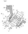
- An example of the configuration as to such a combustor is disclosed, for instance, in the patent reference 1 ( JP2008-25910 ); the disclosed configuration as to the combustor in the patent reference 1 is hereby explained in consultation with Figs. 6 and 7 .
- the inner tube 104 of the combustor is anchored to the outer casing so that the inner tube is supported by the outer casing and a predetermined space is kept between the outer casing and the inner tube; the tail pipe 106 of the combustor is connected to the tip end side of the inner tube 104 so that a casing of the combustor is formed.
- the pilot nozzle 108 is arranged in the middle center area of the inner casing 104; on the other hand, along the hoop direction of the inner surface of the inner tube 104, a plurality of main nozzles 110 is arranged so as to surround the pilot nozzle 108.
- the pilot cone 112 is fitted to the tip part of the pilot nozzle 108.
- a plurality of top-hat nozzles 114 is arranged along the hoop direction of the inner surface of the outer casing 102.
- an end part of the outer casing lid part 118 is fastened to the base end part of the outer casing body 116, with a plurality of fastening bolts 120; at another end part of the outer casing lid part 118, the base end part of the inner tube 104 is fitted so that the air passage 122 is formed between the outer casing lid part 118 and the inner tube 104. Further, the tip end part of each main nozzle communicates with the main burner 124.
- the top-hat forming part 126 is fitted into the outer casing lid part 118 , being fastened to the outer casing lid part 118 with a plurality of the fastening bolts 128.
- the top-hat nozzles 114 are configured in the top-hat forming part 126; namely, a plurality of fuel cavities 130 is formed along the hoop direction of the top-hat forming part 126; a plurality of first fuel passages 132 is formed from each cavity toward the outer casing lid part 118.
- a second fuel passage 134 is formed toward the air passage 122; each second fuel passage 134 is connected to a peg 136 that is fitted to the inner surface of the top-hat forming part 126.
- a pilot fuel line (not shown) is connected to the fuel port 138 for the pilot nozzle 108 and supplies pilot fuel f p into the combustor;
- a main fuel line (not shown) is connected to the fuel port 140 for the main nozzles 110 and supplies main fuel f m into the combustor;
- a top-hat fuel line (not shown) is connected to the fuel port 142 for the top-hat nozzles 114 and supplies main fuel f t into the combustor.
- the compressed air of a high temperature and a high pressure is supplied from the airflow channel 144 toward the air passage 122 along the direction of the arrow a, the compressed air is premixed with the fuel f t that is injected through the top-hat nozzles 114; the premixed air-fuel mixture streams into the inner side of the inner tube 104.
- the air-fuel mixture (being premixed as described above) is further premixed with the fuel f m that is injected through the main nozzle 110, turning into a revolution flow and streaming into the inner side of the tail pipe 106 of the combustor.
- the premixed air-fuel mixture is mixed with the fuel f p that is injected through the pilot nozzle 108 so that the finally premixed air-fuel mixture is ignited by a pilot flame (not shown), is burnt, turns into combustion gas and blows out into the inner side of the tail pipe 106; thereby, a part of the combustion gas blows out into the inner side of the tail pipe 106, accompanying the flame propagation so that the combustion gas diffuses; the combustion gas that diffuses in this way ignites the air-gas mixture that streams from the main nozzles toward the tail pipe 106; thus, the combustion continues.
- a pilot flame not shown
- the lean air-fuel mixture produced by the fuel from the main nozzles 110 can stably burns thanks to the diffusion frame propagation produced by the pilot fuel that is injected through the pilot nozzle 108, the flame propagation can be prevented from reducing inflammation. Further, the compressed air is firstly mixed with the fuel injected through the top-hat nozzles 114; this approach can bring the reduction of NOx produced in the gas turbine.
- the fuel flow rate and the airflow rate are predetermined on the basis of the generator output (demand power), the ambient temperature and so on; the fine adjustments of the operation conditions as to the gas turbine and the plant thereof are performed in the test operations or the commissioning operation; after commissioning, the gas turbine and the plant thereof are operated on the basis of the fine adjusted operation conditions.
- the operation state conditions cannot respond to, for example, the change of fuel contents during the operation. Accordingly, by the limitation of the ability of the conventional control device, the combustion stability is often hindered or the combustion vibrations are often caused.
- the patent reference 2 JP1993-187271 discloses a control device by which the airflow rate or the fuel flow rate as to the gas turbine combustor is controlled on the basis of the changes regarding the ambient temperature, the ambient humidity, the fuel calorific value and so on. According to the technology of the patent reference 2, in response to the technological requirement as described above, the bias control regarding the airflow rate or the fuel flow rate is made use of in order to improve the robustness for the combustion stability.
- the airflow rate or the fuel flow rate is uniformly controlled when the bias control is applied; thus, the degree of freedom as to the control is limited; therefore, it is difficult to adjust the airflow rate or the fuel flow rate so that either of the flow rates converges to an optimally controlled value.
- the present invention aims at improving the stability of the combustion as well as preventing the combustion vibrations from happening, by enhancing the degree of freedom regarding the control settings in a case where the airflow rate or the fuel flow rate is optimally adjusted in response to the target power output corresponding to the load demanded on the generator in the gas turbine plant.
- the present invention discloses a gas turbine control device for controlling a fuel flow rate or an airflow rate in response to a target power output of the gas turbine, the fuel and the air being supplied to a plurality of combustors, the device comprising:
- the fuel flow rate or the airflow rate is established in response to the target power output; a correction value to correct the established fuel flow rate or the established airflow rate is set by the second function generator, on the basis of the detected value as to the suction air temperature at the air inlet of the compressor.
- the present invention pays attention to the suction air temperature as a control variable (parameter) to be used for controlling the fuel flow rate or the airflow rate in order to maintain the stable combustion of the gas turbine.
- the ambient air temperature is selected as a control variable; however, the ambient air temperature does not necessarily uniquely correspond to the suction air temperature. Both the ambient air temperature and the suction air temperature are correlated to some extent; the suction air temperature changes in response to the flow speed thereof; the greater the flow speed, the higher the temperature drop of the suction air temperature after being inhaled.
- the mass balance (the mass flow balance) and the heat balance as to the gas turbine can be known more correctly.
- the suction air temperature rather than the ambient air temperature as a state variable (parameter) in relation to the gas turbine control.
- the amendment value to amend the correction value established in the second function generator as to the fuel flow rate or the airflow rate is set in taking the target power output into consideration; thus, the fuel flow rate or the airflow rate can be optimally adjusted in response to the target power output. Accordingly, in comparison with the approach of the patent reference 2, the present invention provides an approach of greater freedom of control thereby combustion vibrations are prevented and stable combustions are maintained.
- gas turbine control device further comprising:
- the contents of the fuel or the calorific value of the fuel is also taken into consideration, as a parameter to be used for the control of the gas turbine; based on the parameter, a second correction value to correct the fuel flow rate or the airflow rate is established; further, a second correction-amendment value to amend the established second correction value is set, in taking the target power output into consideration; thus, the second correction-amendment value is computed; based on the second correction-amendment value, an order fuel flow rate or an order airflow rate is determined.
- the stable combustion of the gas turbine is maintained without producing combustion vibrations, even in a case where the contents of the fuel, the calorific value of the fuel, or the percentage content of the inert gas included in the fuel fluctuates.
- another preferable embodiment of the present invention is the gas turbine control device, wherein a detecting means for detecting the contents or the calorific value of the fuel is provided on the fuel supply main-pipe at the upstream side of the combustor; and, the second correction value is established on the basis of the detected values detected by the detecting means.
- the contents of the fuel or the calorific value of the fuel can be specified in advance, or can be inputted every time the contents or the calorific value of the fuel changes.
- the contents or the calorific value of the fuel is preferably detected by a detecting means provided on the fuel supply main-pipe.
- the detecting means can detect the contents or the calorific value, even when the value thereof changes during the gas turbine operation; the contents or the calorific value can be detected without stopping the gas turbine operation; thus, the second correction value can be established in response to the changing value as to the contents or the calorific value of the fuel, while the gas turbine is placed under operation.
- the target power output is a load index with respect to the load demanded on the generator connected to the gas turbine or the temperature of the combustion gas flowing into the combustor; and, to be controlled variable is one of:
- the fuel flow rate control valves, the inlet guide vanes, or the bypass valves it becomes easy to adjust the fuel flow rate or the airflow rate; the flow rate of the fuel or the air supplied to each combustor can be properly set in relation to the suction air temperature, the contents of the fuel, or the calorific value of the fuel; accordingly, the combustion control can be realized thereby the gas turbine operation is hard to be influenced by the fluctuations regarding the suction air temperature, the contents of the fuel, or the calorific value of the fuel.
- the target power output is a load index with respect to the load demanded on the generator connected to the gas turbine or the temperature of the combustion gas flowing into the turbine; and, to be controlled variable is one of:
- the flow rate of the fuel supplied to each combustor can be properly set without fluctuating the total fuel flow rate, even in a case where the suction air temperature, the contents of the fuel, or the calorific value of the fuel fluctuates; accordingly, the combustion control can be realized thereby the gas turbine operation is hard to be influenced by the change in the load demanded on the generator or the combustion temperature, even in a case where the suction air temperature, the contents of the fuel, or the calorific value of the fuel fluctuates.
- the present invention provides a gas turbine control device for controlling the fuel flow rate or the airflow rate in response to the target power output of the gas turbine, the fuel and the air being supplied to a plurality of combustors, the device comprising:
- the degree of freedom regarding the gas turbine control can be enhanced; further, in response to the target power output, the optimum control regarding the fuel flow rate or the airflow rate can be performed by use of the suction air temperature as a parameter for the control; thus, even when the weather condition fluctuates, the combustion of the gas turbine can be stably maintained, and combustion vibrations can be prevented.
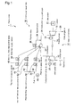
- Fig. 1 shows the configuration of the gas turbine plant according to a first embodiment of the present invention.
- a gas turbine 1 is provided with a gas-turbine body 10 and a combustor assembly 30.
- the gas-turbine body (assembly) 10 is provided with a compressor 12 having a plurality of inlet guide vanes 14, a rotating shaft 16, and a turbine 18; a generator 20 is connected to the turbine 18.
- a suction air temperature sensor 22 for detecting the temperature of the suction air s passing through the space among the inlet guide vanes 14 is provided; the detected value (signal) detected by the suction air temperature sensor 22 is inputted into a gas turbine control unit 60 for controlling the gas turbine plant according to the present embodiment; incidentally, the explanation about the gas turbine control unit 60 will be given later.
- the turbine 18 is connected to a combustion gas guide pipe 26 and an exhaust gas pipe 28 that discharges combustion exhaust gas e outward; Further, the turbine 18 is connected to the compressor 12 and the generator 20 via the rotating shaft 16. The produced combustion gas is supplied to the turbine 18 through the combustion gas guide pipe 26; the exhaust gas rotates the turbine 18; the rotation movement is transmitted to the generator 20 and the compressor 12.
- the combustion gas that is used for the power generation is discharged outward as the exhaust gas e through the exhaust gas pipe 28.
- the temperature sensor 19 for detecting the temperature of the combustion gas guided through the combustion gas guide pipe 26 is fitted.
- the detected value (signal) detected by the temperature sensor 19 is inputted into the gas turbine control unit 60 as described later.
- the compressor 12 is connected to an ambient air guide pipe 13 and a compressed air guide duct 24; the compressor 12 is coupled with the turbine 18 and the generator 20 via the rotating shaft 16; the rotation movement of the turbine 18 is transmitted to the compressor 12 and the compressor 12 rotates; by the rotation movement of the compressor 12, the ambient air is inhaled through the ambient air guide pipe 13; the suction air s thus inhaled is compressed and delivered to the combustors.
- the inlet guide vanes of the compressor are provided at the passage of the suction air s; the flow rate of the suction air s can be adjusted by adjusting the attack angles of the inlet guide vanes on the condition that the rotation speed of the compressor is constant.
- the gas turbine control unit 60 controls the attack angle, as described later.
- the combustor 32 is connected to the compressed air guide duct 24 and the combustion gas guide pipe 26.
- the configuration of the combustor 32 is the same as that of a combustor assembly 100 shown in Figs. 6 and 7 .
- the suction air s is guided to the combustor 32 through the compressed air guide duct 24.
- a bypass pipe 34 is connected to the compressed air guide duct 24 and the combustion gas guide pipe 26; on a part way of the bypass pipe 34, a bypass valve is installed.
- the bypass valve 36 controls the flow rate of the suction air guided to the combustor 32.
- the gas turbine control unit 60 controls the opening of the bypass valve, as described later.
- the fuel f is supplied to the combustor 32 from a fuel supply main-pipe 38 through three branch pipes 40,42 and 44; on the fuel supply main-pipe 38, a calorimeter 46 for detecting the calorific value of the fuel f is fitted; at the branch pipe 40, namely, a main fuel supply pipe 40, a main fuel flow rate control valve 48 is installed; between the control valve 48 and the combustor 32, a main fuel supply valve 50 is installed; at the branch pipe 42, namely, a top-hat fuel supply pipe 42, a top-hat fuel flow rate control valve 52 is installed; between the control valve 52 and the combustor 32, a top-hat fuel supply valve 54 is installed; at the branch pipe 44, namely, a pilot fuel supply pipe 44, a pilot fuel flow rate control valve 56 is installed; between the control valve 56 and the combustor 32, a pilot fuel supply valve 58 is installed.
- the fuel f m delivered from the main fuel supply pipe 40 is supplied to a fuel port 140 communicating with a plurality of main (fuel) nozzles 110; the fuel f t delivered from the top-hat fuel supply pipe 42 is supplied to a fuel port 142 communicating with a plurality of top-hat (fuel) nozzles 114; the fuel f p delivered from pilot fuel supply pipe 44 is supplied to a fuel port 138 communicating with a pilot (fuel) nozzle 108.
- the fuel f is burned in the combustor 32 according to the combustion method described above.
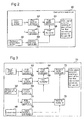
- Fig. 2 shows a gas turbine control unit 60 according to the first embodiment; in Fig. 2 , the target power output of the gas turbine is specified.
- the target power output may be a target value corresponding to the load requirement (MW) on the generator or a target value that is specified on the basis of the temperature of the combustion gas guided into the turbine 18.
- the target value as the target power output is specified as a non-dimensional value in an interval such as 50% to 100% ([0.5, 1.0]); thereby, the 100% corresponds to full load.
- the fuel flow rate as to the fuel flow delivered through the fuel supply main-pipe 38 is specified (established) in a first function generator 62; the specified value (as to the fuel flow rate) is inputted into a first adder-subtractor 64.
- the suction air temperature detected by the suction air temperature sensor 22 is inputted into a second function generator 69 in which a correction value (a first correction value) is established in response to the suction air temperature; the correction value established in the second function generator 69 is inputted into a first multiplier 68.
- a correction value a first correction value
- the setting value as to the fuel flow rate needs to be amended under the condition that the combustion state fluctuations are taken into consideration; thus, another target power output (a second target power output) is inputted into a third function generator 66 in which an amendment value (a first amendment value) is established; the amendment value established in the third function generator 66 is inputted into the first multiplier 68.
- a correction-amendment value (an overall correction value for the fuel flow rate setting value) is computed on the basis of the a first correction value established in the second function generator 69 in response to the suction air temperature and the first amendment value established in the third function generator 66 in response to the second target power output; and, the correction-amendment value (the overall correction value for the fuel flow rate setting value) is inputted into the first adder-subtractor 64; in the first adder-subtractor 64, the correction-amendment value is added to (or subtracted from) the fuel flow rate setting value specified in a first function generator 62.
- the fuel flow rate in response to the first target power output and the second target power output is determined.
- the opening of each of the fuel valves 48, 52, and 56 is determined according to a function expressed with the parameters as to the valve opening characteristics of each valve as well as the parameters such as fuel temperature and fuel pressure; the order signals for controlling the opening of each of the fuel valves 48, 52, and 56 are issued from the gas turbine control unit 60 toward each of the fuel valves 48, 52 and 56.
- the fuel flow rates through each of the fuel valves 48, 52, and 56 are determined; the opening of each of the fuel valves 48, 52, and 56 can respond to the detected suction air temperature at the air inlet of the compressor 12; further, since the opening of each of the fuel valves is controlled so that the valve opening reflects the combustion characteristics regarding the target power output, the each fuel flow rate can be optimal in response to the target power output. Hence, the operation of the gas turbine can be continued in a stable combustion condition, without combustion vibrations. Moreover, the degree of freedom regarding the control settings can be enhanced, in comparison with the bias control (regarding the airflow rate or the fuel flow rate) disclosed in the patent reference 2.
- the fuel flow rate as to the fuel flow delivered through the fuel supply main-pipe 38 is specified by the first function generator 62; the summation of the first correction value and the first amendment value is calculated by the first adder-subtractor 64, and, the fuel flow rate in response to the target power output is determined.
- each of the fuel flow rates through the main fuel supply pipe 40, the top-hat fuel supply pipe, and the pilot fuel supply pipe 42 is specified by the first function generator 62; and, the correction-amendment value (for the summation of the fuel flow rates) is calculated by the first adder-subtractor 64 so that the main fuel flow rate, the top-hat fuel flow rate, and the pilot fuel flow rate are determined in response to the target power output.
- an approach in which the fuel flow rate is controlled is adopted; instead, preferably, there may be an approach in which the flow rate of the compressed air guided from the compressed air guide duct 24 into the combustor 32 is controlled.
- the attack angle of each inlet guide vane 14 is adjusted so as to control the compressed airflow rate; or, the opening of the bypass valve 36 is adjusted so as to control the compressed airflow rate.
- the temperature sensor 19 for detecting the temperature of the combustion gas is provided at the inlet of the turbine 18.
- the temperature of the combustion gas is estimated through arithmetic calculations as to the detected-values detected by other temperature sensors and flow rate meters, with respect to heat balance and mass balance.
- a second embodiment according to the present invention is now explained with reference to Fig. 3 .
- the components such as the function generators, the adder-subtractors or the multipliers
- the components in Fig. 2 in relation to the first embodiment are common components over Figs. 2 and 3 ; naturally, the common components have the same function.
- a calorimeter 46 is provided on the fuel supply main-pipe so as to detect the specific heat value of the fuel f; and, in response to the detected-value detected by the calorimeter 46, a second correction value is established in a fourth function generator 78, the second correction value being a correction value for the setting of the fuel flow rate. Further, in a fifth function generator 74, a second amendment value for amending the second correction value in consideration of the target power output (the first target power output) is established.
- the second correction value established in the fourth function generator 78 and the second amendment value established in the fifth function generator 74 are inputted into a second multiplier 76, in which a second correction-amendment value is calculated.
- the second correction- amendment value is inputted into a second adder-subtractor 72.
- the first correction-amendment value is added to (or subtracted from) the fuel flow rate setting value specified in the first function generator 62 in response to the target power output; subsequently, in a second adder-subtractor 72, the second correction-amendment value is added to (or subtracted from) the first correction-amendment value.
- the flow rate of the fuel supplied to the combustor 32 is determined; based on the determined fuel flow rate, the opening of each of the fuel valves 48. 52, and 56 is to be determined according to a function expressed with the parameters as to the valve opening characteristics of each valve as well as the parameters such as fuel temperature and fuel pressure.
- the detected calorific value of the fuel f is taken into consideration as a parameter of an additional kind.
- the fuel flow rate setting value is corrected; further, the corrected value is amended in response to the target power output; thus, in addition to the effect brought by the first embodiment, the second embodiment can realize the effectiveness of maintaining the stable combustion without producing combustion vibrations, even in a case where the contents of the fuel, the calorific value of the fuel, or the percentage content of the inert gas included in the fuel fluctuates.
- an approach in which the fuel flow rate is controlled is adopted; instead, preferably, there may be an approach in which the flow rate of the compressed air guided from the compressed air guide duct 24 into the combustor 32 is controlled.
- the attack angle of each inlet guide vane 14 is adjusted so as to control the compressed airflow rate; or, the opening of the bypass valve 36 is adjusted so as to control the compressed airflow rate.
- the calorimeter 46 is provided on the part way of the fuel supply main-pipe.
- the calorific value is estimated through the arithmetic calculations by use of the values as to the generator output and the fuel flow rate.
- a third embodiment according to the present invention is now explained with reference to Figs. 4 and 5 .
- the temperature of the combustion gas at the gas inlet of the turbine 18 is adopted as a variable (parameter) to be established corresponding to the target power output.
- the temperature sensor 19 detects the temperature of the combustion gas.
- the gas inlet temperature as an index of the target power output is, for instance, directed to a value between 1480 to 1500°C.
- the configuration components (such as the function generators, the adder-subtractors or the multipliers) of a gas turbine control unit 80 are the same as those in Fig. 3 ; the common components over Figs. 3 and 4 are marked with the same numerals or symbols.
- the combustion temperature is used as a variable (parameter) that corresponds to the target power output; as is the case with the second embodiment, the control parameters comprise the suction air temperature detected by the suction air temperature sensor 22 and the calorific value of the fuel f detected by the calorimeter 46;
- the first function generator 62 establishes the fuel ratios that are, for instance, the percentage ratios of the main fuel flow rate, the top-hat fuel flow rate and the pilot fuel flow rate in the total fuel flow rate.
- the first correction- amendment value is added to (or subtracted from) each fuel ratio; subsequently, in the second adder-subtractor 72, the second correction-amendment value is added to (or subtracted from) the each result by the first correction-amendment.
- the ratio of the top-hat fuel flow rate to the total fuel flow rate, the ratio of the pilot fuel flow rate to the total fuel flow rate, and the ratio of the main fuel flow rate to the total fuel flow rate are called the top-hat fuel flow ratio, the pilot fuel flow ratio, and the main fuel flow ratio, respectively.
- the order signal as to the opening of each of the fuel valves 48, 52, and 56 is issued.
- the steps of determining the opening of each of the fuel valves 48, 52, and 56 are on the basis of the determined fuel flow rate ratios are now explained with reference to Fig. 5 ; thereby, the pilot fuel flow rate is calculated by use of the pilot fuel flow ratio and the total flow rate; the top-hat fuel flow rate is calculated by use of the top-hat fuel flow ratio and the total flow rate; further, at the comparator 84, the main fuel flow rate is calculated by subtracting the pilot fuel flow rate and the top-hat fuel flow rate from the total fuel flow rate.
- the order signal for controlling the opening of each of the fuel flow rate control valves 48, 52, and 56 is issued toward the corresponding fuel flow rate control valve; thereby, before being issued, each signal for each corresponding fuel flow rate control valve is corrected, at correctors 86, 88 and 90 (in Fig. 5 ), so as to reflect the effect of the parameters such as fuel temperature and fuel pressure.
- the temperature sensor 19 for detecting the temperature of the combustion gas is provided at the inlet of the turbine 18.
- the temperature of the combustion gas is estimated through arithmetic calculations as to the detected-values detected by other temperature sensors and flow rate meters, with respect to heat balance and mass balance.
- the control parameters comprise the suction air temperature detected by the suction air temperature sensor 22 and the calorific value of the fuel f detected by the calorimeter 46; further, the temperature of the combustion gas at the gas inlet of the turbine 18 is adopted as a variable (parameter) to be established corresponding to the target power output; thus, in addition to the effect brought by the second embodiment, the third embodiment can realize the effectiveness of restraining the influence of the seasonal change in the suction air temperature on the combustion stability inside the combustor, to a minimal level.
- a stable combustion operation of a gas turbine plant can be realized with a simple control mechanism, without producing combustion vibrations, in a case where the suction air temperature changes or the calorific value of the supplied fuel fluctuates, for instance, because of the increase of the inert gas components in the fuel.
Landscapes
- Engineering & Computer Science (AREA)
- Chemical & Material Sciences (AREA)
- Combustion & Propulsion (AREA)
- Mechanical Engineering (AREA)
- General Engineering & Computer Science (AREA)
- Physics & Mathematics (AREA)
- Fluid Mechanics (AREA)
- Control Of Turbines (AREA)
- Regulation And Control Of Combustion (AREA)
Abstract
Description
- The present invention relates to a gas turbine control device that controls a gas turbine so that the gas turbine can maintain stable combustion without combustion vibrations even in a case where the ambient temperature, the fuel content, or the fuel calorific value changes in the gas turbine plant in which the gas turbine is operated.
- There are several types of combustion nozzles provided in a combustor of a gas turbine; for instance, there are a main nozzle that is used for premix combustion and a pilot nozzle that is used for diffusion combustion; further, a certain combustor is provided with a top-hat nozzle that is used for NOx reduction during high load operation as well as combustion stability during low load operation. An example of the configuration as to such a combustor is disclosed, for instance, in the patent reference 1 (
JP2008-25910 Figs. 6 and7 . - Within the
outer casing 102 of thecombustor 100, theinner tube 104 of the combustor is anchored to the outer casing so that the inner tube is supported by the outer casing and a predetermined space is kept between the outer casing and the inner tube; thetail pipe 106 of the combustor is connected to the tip end side of theinner tube 104 so that a casing of the combustor is formed. In the middle center area of theinner casing 104, thepilot nozzle 108 is arranged; on the other hand, along the hoop direction of the inner surface of theinner tube 104, a plurality ofmain nozzles 110 is arranged so as to surround thepilot nozzle 108. Thepilot cone 112 is fitted to the tip part of thepilot nozzle 108. Further, a plurality of top-hat nozzles 114 is arranged along the hoop direction of the inner surface of theouter casing 102. - As shown in
Fig. 7 , an end part of the outercasing lid part 118 is fastened to the base end part of theouter casing body 116, with a plurality offastening bolts 120; at another end part of the outercasing lid part 118, the base end part of theinner tube 104 is fitted so that theair passage 122 is formed between the outercasing lid part 118 and theinner tube 104. Further, the tip end part of each main nozzle communicates with themain burner 124. - The top-
hat forming part 126 is fitted into the outercasing lid part 118 , being fastened to the outercasing lid part 118 with a plurality of thefastening bolts 128. As shown inFig. 7 , the top-hat nozzles 114 are configured in the top-hat forming part 126; namely, a plurality offuel cavities 130 is formed along the hoop direction of the top-hat forming part 126; a plurality offirst fuel passages 132 is formed from each cavity toward the outercasing lid part 118. At the front end of eachfirst fuel passage 132, asecond fuel passage 134 is formed toward theair passage 122; eachsecond fuel passage 134 is connected to apeg 136 that is fitted to the inner surface of the top-hat forming part 126. - A pilot fuel line (not shown) is connected to the
fuel port 138 for thepilot nozzle 108 and supplies pilot fuel fp into the combustor; a main fuel line (not shown) is connected to thefuel port 140 for themain nozzles 110 and supplies main fuel fm into the combustor; a top-hat fuel line (not shown) is connected to thefuel port 142 for the top-hat nozzles 114 and supplies main fuel ft into the combustor. - In the configuration described above, when the compressed air of a high temperature and a high pressure is supplied from the
airflow channel 144 toward theair passage 122 along the direction of the arrow a, the compressed air is premixed with the fuel ft that is injected through the top-hat nozzles 114; the premixed air-fuel mixture streams into the inner side of theinner tube 104. - Inside of the
inner tube 104, the air-fuel mixture (being premixed as described above) is further premixed with the fuel fm that is injected through themain nozzle 110, turning into a revolution flow and streaming into the inner side of thetail pipe 106 of the combustor. - Further, the premixed air-fuel mixture is mixed with the fuel fp that is injected through the
pilot nozzle 108 so that the finally premixed air-fuel mixture is ignited by a pilot flame (not shown), is burnt, turns into combustion gas and blows out into the inner side of thetail pipe 106; thereby, a part of the combustion gas blows out into the inner side of thetail pipe 106, accompanying the flame propagation so that the combustion gas diffuses; the combustion gas that diffuses in this way ignites the air-gas mixture that streams from the main nozzles toward thetail pipe 106; thus, the combustion continues. In other words, since the lean air-fuel mixture produced by the fuel from themain nozzles 110 can stably burns thanks to the diffusion frame propagation produced by the pilot fuel that is injected through thepilot nozzle 108, the flame propagation can be prevented from reducing inflammation. Further, the compressed air is firstly mixed with the fuel injected through the top-hat nozzles 114; this approach can bring the reduction of NOx produced in the gas turbine. - In the conventional gas turbine plants, the fuel flow rate and the airflow rate are predetermined on the basis of the generator output (demand power), the ambient temperature and so on; the fine adjustments of the operation conditions as to the gas turbine and the plant thereof are performed in the test operations or the commissioning operation; after commissioning, the gas turbine and the plant thereof are operated on the basis of the fine adjusted operation conditions. According to the conventional control device for the gas turbine plant, however, the operation state conditions cannot respond to, for example, the change of fuel contents during the operation. Accordingly, by the limitation of the ability of the conventional control device, the combustion stability is often hindered or the combustion vibrations are often caused.
- In a case where combustion vibrations occur, the vibrations seriously hinder the operation of the gas turbine; hence, it is strongly required to restrain the combustion vibrations of the gas turbine as far as possible, in view of the protection of the plant facility and the enhancement of the plant availability.
- The patent reference 2 (
JP1993-187271 - In the control means disclosed in the patent reference 2, the airflow rate or the fuel flow rate is uniformly controlled when the bias control is applied; thus, the degree of freedom as to the control is limited; therefore, it is difficult to adjust the airflow rate or the fuel flow rate so that either of the flow rates converges to an optimally controlled value.
- In view of the difficulties in the conventional technologies as described above, the present invention aims at improving the stability of the combustion as well as preventing the combustion vibrations from happening, by enhancing the degree of freedom regarding the control settings in a case where the airflow rate or the fuel flow rate is optimally adjusted in response to the target power output corresponding to the load demanded on the generator in the gas turbine plant.
- In order to overcome the difficulties described above, the present invention discloses a gas turbine control device for controlling a fuel flow rate or an airflow rate in response to a target power output of the gas turbine, the fuel and the air being supplied to a plurality of combustors, the device comprising:
- a first function generator for establishing the fuel flow rate or the airflow rate, in response to the target power output, the fuel and the air being supplied to each combustor;
- a second function generator for establishing a correction value to correct the established fuel flow rate or the established airflow rate on the basis of the suction air temperature detected by a suction air temperature sensor that is provided so as to detect the suction air temperature at an air inlet of the compressor;
- a third function generator for establishing an amendment value to amend the established correction value as to the fuel flow rate or the airflow rate, in taking the target power output into consideration;
- a first computing element for computing a correction-amendment value by use of the correction value established by the second function generator and the amendment value established by the third function generator;
- a second computing element for computing an order fuel flow rate or an order airflow rate by adding the correction-amendment value to the fuel flow rate or the airflow rate either of which is established in the first function generator, the order fuel flow rate or the order airflow rate being used to determine the flow rate as to the fuel or the air to be supplied to the combustor.
- In the present invention, the fuel flow rate or the airflow rate is established in response to the target power output; a correction value to correct the established fuel flow rate or the established airflow rate is set by the second function generator, on the basis of the detected value as to the suction air temperature at the air inlet of the compressor. In other words, the present invention pays attention to the suction air temperature as a control variable (parameter) to be used for controlling the fuel flow rate or the airflow rate in order to maintain the stable combustion of the gas turbine.
- In the patent reference 2, the ambient air temperature is selected as a control variable; however, the ambient air temperature does not necessarily uniquely correspond to the suction air temperature. Both the ambient air temperature and the suction air temperature are correlated to some extent; the suction air temperature changes in response to the flow speed thereof; the greater the flow speed, the higher the temperature drop of the suction air temperature after being inhaled.
- By detecting the suction air temperature that is the temperature of the air inhaled into the gas turbine, rather than by detecting the ambient air temperature, the mass balance (the mass flow balance) and the heat balance as to the gas turbine can be known more correctly. Thus, in order to maintain the combustion stability without being influenced by the changes of weather condition, it is advantageous to use the suction air temperature rather than the ambient air temperature as a state variable (parameter) in relation to the gas turbine control.
- Further, in the third function generator, the amendment value to amend the correction value established in the second function generator as to the fuel flow rate or the airflow rate is set in taking the target power output into consideration; thus, the fuel flow rate or the airflow rate can be optimally adjusted in response to the target power output. Accordingly, in comparison with the approach of the patent reference 2, the present invention provides an approach of greater freedom of control thereby combustion vibrations are prevented and stable combustions are maintained.
- Further, another preferable embodiment of the present invention is the gas turbine control device, further comprising:
- a fourth function generator for establishing a second correction value to correct the fuel flow rate or the airflow rate established in the first function generator, in response to the contents or the calorific value of the fuel;
- a fifth function generator for establishing a second amendment value to amend the established second correction value, in taking the target power output into consideration;
- a third computing element for computing a second correction-amendment value by use of the second correction value established by the fourth function generator and the second amendment value established by the fifth function generator;
- a fourth computing element for computing an order fuel flow rate or an order airflow rate by adding the correction-amendment value and the second correction-amendment value to the fuel flow rate or the airflow rate, the order fuel flow rate or the order airflow rate being used to determine the flow rate as to the fuel or the air to be supplied to the combustor.
- As described above, the contents of the fuel or the calorific value of the fuel is also taken into consideration, as a parameter to be used for the control of the gas turbine; based on the parameter, a second correction value to correct the fuel flow rate or the airflow rate is established; further, a second correction-amendment value to amend the established second correction value is set, in taking the target power output into consideration; thus, the second correction-amendment value is computed; based on the second correction-amendment value, an order fuel flow rate or an order airflow rate is determined. Thus, the stable combustion of the gas turbine is maintained without producing combustion vibrations, even in a case where the contents of the fuel, the calorific value of the fuel, or the percentage content of the inert gas included in the fuel fluctuates.
- Further, another preferable embodiment of the present invention is the gas turbine control device, wherein a detecting means for detecting the contents or the calorific value of the fuel is provided on the fuel supply main-pipe at the upstream side of the combustor; and, the second correction value is established on the basis of the detected values detected by the detecting means. The contents of the fuel or the calorific value of the fuel can be specified in advance, or can be inputted every time the contents or the calorific value of the fuel changes. However, as described in this embodiment, the contents or the calorific value of the fuel is preferably detected by a detecting means provided on the fuel supply main-pipe. In addition, preferably, there may be an approach in which the calorific value is estimated through the arithmetic calculations by use of the values as to the generator output and the fuel flow rate.
- Hence, it becomes not necessary to specify the contents or the calorific value of the fuel in advance; further, the detecting means can detect the contents or the calorific value, even when the value thereof changes during the gas turbine operation; the contents or the calorific value can be detected without stopping the gas turbine operation; thus, the second correction value can be established in response to the changing value as to the contents or the calorific value of the fuel, while the gas turbine is placed under operation.
- Further, another preferable embodiment of the present invention is the gas turbine control device, wherein the target power output is a load index with respect to the load demanded on the generator connected to the gas turbine or the temperature of the combustion gas flowing into the combustor; and, to be controlled variable is one of:
- the opening of a plurality of fuel flow rate control valves provided on the fuel supply pipes connecting the fuel supply main-pipe with each combustor;
- the attack angle of a plurality of inlet guide vanes provided in the compressor of the gas turbine; or,
- the opening of the bypass valves provided on each air bypass pipe passing the air compressed by the compressor so that the compressed air bypasses the combustion gas area in each combustor.
- As described above, by controlling the fuel flow rate control valves, the inlet guide vanes, or the bypass valves, it becomes easy to adjust the fuel flow rate or the airflow rate; the flow rate of the fuel or the air supplied to each combustor can be properly set in relation to the suction air temperature, the contents of the fuel, or the calorific value of the fuel; accordingly, the combustion control can be realized thereby the gas turbine operation is hard to be influenced by the fluctuations regarding the suction air temperature, the contents of the fuel, or the calorific value of the fuel.
- Further, another preferable embodiment of the present invention is the gas turbine control device, wherein the target power output is a load index with respect to the load demanded on the generator connected to the gas turbine or the temperature of the combustion gas flowing into the turbine; and, to be controlled variable is one of:
- the pilot fuel ratio that is the percentage ratio of the pilot fuel flow rate to the total fuel flow rate; or,
- the top-hat fuel ratio that is the percentage ratio of the top-hat fuel flow rate to the total fuel flow rate.
- As described above, by controlling the ratio of the pilot fuel flow rate or the top-hat fuel flow rate to the total fuel flow rate, the flow rate of the fuel supplied to each combustor can be properly set without fluctuating the total fuel flow rate, even in a case where the suction air temperature, the contents of the fuel, or the calorific value of the fuel fluctuates; accordingly, the combustion control can be realized thereby the gas turbine operation is hard to be influenced by the change in the load demanded on the generator or the combustion temperature, even in a case where the suction air temperature, the contents of the fuel, or the calorific value of the fuel fluctuates.
- As described above, the present invention provides a gas turbine control device for controlling the fuel flow rate or the airflow rate in response to the target power output of the gas turbine, the fuel and the air being supplied to a plurality of combustors, the device comprising:
- a first function generator for establishing the fuel flow rate or the airflow rate, in response to the target power output, the fuel and the air being supplied to each combustor;
- a second function generator for establishing a correction value to correct the established fuel flow rate or the established airflow rate on the basis of the suction air temperature detected by a suction air temperature sensor that is provided so as to detect the suction air temperature at the air inlet of the compressor;
- a third function generator for establishing an amendment value to amend the established correction value as to the fuel flow rate or the airflow rate, in taking the target power output into consideration;
- a first computing element for computing a correction-amendment value by use of the correction value established by the second function generator and the amendment value established by the third function generator;
- a second computing element for computing an order fuel flow rate or an order airflow rate by adding the correction-amendment value to the fuel flow rate or the airflow rate either of which is established in the first function generator, the order fuel flow rate or the order airflow rate being used to determine the flow rate as to the fuel or the air to be supplied to the combustor.
- In this way, the degree of freedom regarding the gas turbine control can be enhanced; further, in response to the target power output, the optimum control regarding the fuel flow rate or the airflow rate can be performed by use of the suction air temperature as a parameter for the control; thus, even when the weather condition fluctuates, the combustion of the gas turbine can be stably maintained, and combustion vibrations can be prevented.
- The present invention will now be described in greater detail with reference to the preferred embodiments of the invention and the accompanying drawings, wherein:
-
Fig. 1 shows the configuration of the gas turbine plant according to a first embodiment of the present invention; -
Fig. 2 shows a block diagram regarding a gas turbine control unit according to a first embodiment; -
Fig. 3 shows a block diagram regarding a gas turbine control unit according to a second embodiment of the present invention; -
Fig. 4 shows a block diagram regarding a gas turbine control unit according to a third embodiment of the present invention; -
Fig. 5 shows a block diagram regarding the control mechanism of the fuel flow rate control valves according to the third embodiment; -
Fig. 6 shows a longitudinal cross-section of the combustor of the gas turbine; -
Fig. 7 shows an enlargement of a part ofFig. 6 . - Hereafter, the present invention will be described in detail with reference to the embodiments shown in the figures. However, the dimensions, materials, shape, the relative placement and so on of a component described in these embodiments shall not be construed as limiting the scope of the invention thereto, unless especially specific mention is made.
- The device as a first embodiment according to the present invention is now explained with reference to
Figs. 1 and2 .Fig. 1 shows the configuration of the gas turbine plant according to a first embodiment of the present invention. InFig. 1 , a gas turbine 1 is provided with a gas-turbine body 10 and a combustor assembly 30. The gas-turbine body (assembly) 10 is provided with acompressor 12 having a plurality ofinlet guide vanes 14, a rotatingshaft 16, and aturbine 18; agenerator 20 is connected to theturbine 18. A suctionair temperature sensor 22 for detecting the temperature of the suction air s passing through the space among theinlet guide vanes 14 is provided; the detected value (signal) detected by the suctionair temperature sensor 22 is inputted into a gasturbine control unit 60 for controlling the gas turbine plant according to the present embodiment; incidentally, the explanation about the gasturbine control unit 60 will be given later. Theturbine 18 is connected to a combustion gas guide pipe 26 and anexhaust gas pipe 28 that discharges combustion exhaust gas e outward; Further, theturbine 18 is connected to thecompressor 12 and thegenerator 20 via the rotatingshaft 16. The produced combustion gas is supplied to theturbine 18 through the combustion gas guide pipe 26; the exhaust gas rotates theturbine 18; the rotation movement is transmitted to thegenerator 20 and thecompressor 12. The combustion gas that is used for the power generation is discharged outward as the exhaust gas e through theexhaust gas pipe 28. At the combustion gas inlet of theturbine 18, thetemperature sensor 19 for detecting the temperature of the combustion gas guided through the combustion gas guide pipe 26 is fitted. The detected value (signal) detected by thetemperature sensor 19 is inputted into the gasturbine control unit 60 as described later. - The
compressor 12 is connected to an ambientair guide pipe 13 and a compressedair guide duct 24; thecompressor 12 is coupled with theturbine 18 and thegenerator 20 via the rotatingshaft 16; the rotation movement of theturbine 18 is transmitted to thecompressor 12 and thecompressor 12 rotates; by the rotation movement of thecompressor 12, the ambient air is inhaled through the ambientair guide pipe 13; the suction air s thus inhaled is compressed and delivered to the combustors. - The inlet guide vanes of the compressor are provided at the passage of the suction air s; the flow rate of the suction air s can be adjusted by adjusting the attack angles of the inlet guide vanes on the condition that the rotation speed of the compressor is constant. The gas
turbine control unit 60 controls the attack angle, as described later. - In the next place, the combustor assembly 30 is now explained. The combustor 32 is connected to the compressed
air guide duct 24 and the combustion gas guide pipe 26. The configuration of the combustor 32 is the same as that of acombustor assembly 100 shown inFigs. 6 and7 . The suction air s is guided to the combustor 32 through the compressedair guide duct 24. Abypass pipe 34 is connected to the compressedair guide duct 24 and the combustion gas guide pipe 26; on a part way of thebypass pipe 34, a bypass valve is installed. Thebypass valve 36 controls the flow rate of the suction air guided to the combustor 32. The gasturbine control unit 60 controls the opening of the bypass valve, as described later. - The fuel f is supplied to the combustor 32 from a fuel supply main-
pipe 38 through threebranch pipes pipe 38, acalorimeter 46 for detecting the calorific value of the fuel f is fitted; at thebranch pipe 40, namely, a mainfuel supply pipe 40, a main fuel flowrate control valve 48 is installed; between thecontrol valve 48 and the combustor 32, a mainfuel supply valve 50 is installed; at thebranch pipe 42, namely, a top-hatfuel supply pipe 42, a top-hat fuel flowrate control valve 52 is installed; between thecontrol valve 52 and the combustor 32, a top-hatfuel supply valve 54 is installed; at thebranch pipe 44, namely, a pilotfuel supply pipe 44, a pilot fuel flowrate control valve 56 is installed; between thecontrol valve 56 and the combustor 32, a pilotfuel supply valve 58 is installed. - In the configuration described thus far, as shown in
Fig. 7 , the fuel fm delivered from the mainfuel supply pipe 40 is supplied to afuel port 140 communicating with a plurality of main (fuel)nozzles 110; the fuel ft delivered from the top-hatfuel supply pipe 42 is supplied to afuel port 142 communicating with a plurality of top-hat (fuel)nozzles 114; the fuel fp delivered from pilotfuel supply pipe 44 is supplied to afuel port 138 communicating with a pilot (fuel)nozzle 108. Thus, the fuel f is burned in the combustor 32 according to the combustion method described above. -
Fig. 2 shows a gasturbine control unit 60 according to the first embodiment; inFig. 2 , the target power output of the gas turbine is specified. The target power output may be a target value corresponding to the load requirement (MW) on the generator or a target value that is specified on the basis of the temperature of the combustion gas guided into theturbine 18. For instance, in a case where the target value corresponding to the load requirement (MW) is used, the target value as the target power output is specified as a non-dimensional value in an interval such as 50% to 100% ([0.5, 1.0]); thereby, the 100% corresponds to full load. - On the basis of the specified target power output, the fuel flow rate as to the fuel flow delivered through the fuel supply main-
pipe 38 is specified (established) in afirst function generator 62; the specified value (as to the fuel flow rate) is inputted into a first adder-subtractor 64. - In the next place, the suction air temperature detected by the suction
air temperature sensor 22 is inputted into asecond function generator 69 in which a correction value (a first correction value) is established in response to the suction air temperature; the correction value established in thesecond function generator 69 is inputted into afirst multiplier 68. In addition, since the combustion state fluctuates according to the target power output, the setting value as to the fuel flow rate needs to be amended under the condition that the combustion state fluctuations are taken into consideration; thus, another target power output (a second target power output) is inputted into athird function generator 66 in which an amendment value (a first amendment value) is established; the amendment value established in thethird function generator 66 is inputted into thefirst multiplier 68. - In the
first multiplier 68, a correction-amendment value (an overall correction value for the fuel flow rate setting value) is computed on the basis of the a first correction value established in thesecond function generator 69 in response to the suction air temperature and the first amendment value established in thethird function generator 66 in response to the second target power output; and, the correction-amendment value (the overall correction value for the fuel flow rate setting value) is inputted into the first adder-subtractor 64; in the first adder-subtractor 64, the correction-amendment value is added to (or subtracted from) the fuel flow rate setting value specified in afirst function generator 62. Thus, the fuel flow rate in response to the first target power output and the second target power output is determined. - On the basis of the determined fuel flow rate, the opening of each of the
fuel valves fuel valves turbine control unit 60 toward each of thefuel valves - As described above, the fuel flow rates through each of the
fuel valves fuel valves compressor 12; further, since the opening of each of the fuel valves is controlled so that the valve opening reflects the combustion characteristics regarding the target power output, the each fuel flow rate can be optimal in response to the target power output. Hence, the operation of the gas turbine can be continued in a stable combustion condition, without combustion vibrations. Moreover, the degree of freedom regarding the control settings can be enhanced, in comparison with the bias control (regarding the airflow rate or the fuel flow rate) disclosed in the patent reference 2. - In addition, in this first embodiment, the fuel flow rate as to the fuel flow delivered through the fuel supply main-
pipe 38 is specified by thefirst function generator 62; the summation of the first correction value and the first amendment value is calculated by the first adder-subtractor 64, and, the fuel flow rate in response to the target power output is determined. However, preferably, there may be an approach in which each of the fuel flow rates through the mainfuel supply pipe 40, the top-hat fuel supply pipe, and the pilotfuel supply pipe 42 is specified by thefirst function generator 62; and, the correction-amendment value (for the summation of the fuel flow rates) is calculated by the first adder-subtractor 64 so that the main fuel flow rate, the top-hat fuel flow rate, and the pilot fuel flow rate are determined in response to the target power output. - Further, in this first embodiment, an approach in which the fuel flow rate is controlled is adopted; instead, preferably, there may be an approach in which the flow rate of the compressed air guided from the compressed
air guide duct 24 into the combustor 32 is controlled. In this case, the attack angle of eachinlet guide vane 14 is adjusted so as to control the compressed airflow rate; or, the opening of thebypass valve 36 is adjusted so as to control the compressed airflow rate. Further, preferably, there may be an approach in which both the fuel flow rate and the compressed airflow rate are controlled at the same time. - Further, in this first embodiment, at the inlet of the
turbine 18, thetemperature sensor 19 for detecting the temperature of the combustion gas is provided. However, preferably, there may be an approach in which the temperature of the combustion gas is estimated through arithmetic calculations as to the detected-values detected by other temperature sensors and flow rate meters, with respect to heat balance and mass balance. - In the next place, a second embodiment according to the present invention is now explained with reference to
Fig. 3 . InFig. 3 , the components (such as the function generators, the adder-subtractors or the multipliers) that are marked with the same numeral or symbol, as the components inFig. 2 in relation to the first embodiment are common components overFigs. 2 and 3 ; naturally, the common components have the same function. In this second embodiment, in addition to the control approach shown inFig 2 , acalorimeter 46 is provided on the fuel supply main-pipe so as to detect the specific heat value of the fuel f; and, in response to the detected-value detected by thecalorimeter 46, a second correction value is established in afourth function generator 78, the second correction value being a correction value for the setting of the fuel flow rate. Further, in afifth function generator 74, a second amendment value for amending the second correction value in consideration of the target power output (the first target power output) is established. - In the next place, the second correction value established in the
fourth function generator 78 and the second amendment value established in thefifth function generator 74 are inputted into asecond multiplier 76, in which a second correction-amendment value is calculated. The second correction- amendment value is inputted into a second adder-subtractor 72. Further, as is the case with the first embodiment, in the first adder-subtractor 64, the first correction-amendment value is added to (or subtracted from) the fuel flow rate setting value specified in thefirst function generator 62 in response to the target power output; subsequently, in a second adder-subtractor 72, the second correction-amendment value is added to (or subtracted from) the first correction-amendment value. Thus, the flow rate of the fuel supplied to the combustor 32 is determined; based on the determined fuel flow rate, the opening of each of thefuel valves 48. 52, and 56 is to be determined according to a function expressed with the parameters as to the valve opening characteristics of each valve as well as the parameters such as fuel temperature and fuel pressure. - According to this second embodiment, the detected calorific value of the fuel f is taken into consideration as a parameter of an additional kind. On the basis of the detected suction-air temperature at the inlet of the compressor and this detected calorific value of the fuel, the fuel flow rate setting value is corrected; further, the corrected value is amended in response to the target power output; thus, in addition to the effect brought by the first embodiment, the second embodiment can realize the effectiveness of maintaining the stable combustion without producing combustion vibrations, even in a case where the contents of the fuel, the calorific value of the fuel, or the percentage content of the inert gas included in the fuel fluctuates.
- Further, in this first embodiment, an approach in which the fuel flow rate is controlled is adopted; instead, preferably, there may be an approach in which the flow rate of the compressed air guided from the compressed
air guide duct 24 into the combustor 32 is controlled. In this case, the attack angle of eachinlet guide vane 14 is adjusted so as to control the compressed airflow rate; or, the opening of thebypass valve 36 is adjusted so as to control the compressed airflow rate. Further, preferably, there may be an approach in which both the fuel flow rate and the compressed airflow rate are controlled at the same time. Moreover, in this first embodiment, thecalorimeter 46 is provided on the part way of the fuel supply main-pipe. However, preferably, there may be an approach in which the calorific value is estimated through the arithmetic calculations by use of the values as to the generator output and the fuel flow rate. - In the next place, a third embodiment according to the present invention is now explained with reference to
Figs. 4 and 5 . InFig. 4 according to the present embodiment, the temperature of the combustion gas at the gas inlet of theturbine 18 is adopted as a variable (parameter) to be established corresponding to the target power output. Thetemperature sensor 19 detects the temperature of the combustion gas. The gas inlet temperature as an index of the target power output is, for instance, directed to a value between 1480 to 1500°C. InFig. 4 , the configuration components (such as the function generators, the adder-subtractors or the multipliers) of a gasturbine control unit 80 are the same as those inFig. 3 ; the common components overFigs. 3 and4 are marked with the same numerals or symbols. - In the gas
turbine control unit 80, the combustion temperature is used as a variable (parameter) that corresponds to the target power output; as is the case with the second embodiment, the control parameters comprise the suction air temperature detected by the suctionair temperature sensor 22 and the calorific value of the fuel f detected by thecalorimeter 46; In the present embodiment, thefirst function generator 62 establishes the fuel ratios that are, for instance, the percentage ratios of the main fuel flow rate, the top-hat fuel flow rate and the pilot fuel flow rate in the total fuel flow rate. In the first adder-subtractor 64, the first correction- amendment value is added to (or subtracted from) each fuel ratio; subsequently, in the second adder-subtractor 72, the second correction-amendment value is added to (or subtracted from) the each result by the first correction-amendment. Incidentally, the ratio of the top-hat fuel flow rate to the total fuel flow rate, the ratio of the pilot fuel flow rate to the total fuel flow rate, and the ratio of the main fuel flow rate to the total fuel flow rate are called the top-hat fuel flow ratio, the pilot fuel flow ratio, and the main fuel flow ratio, respectively. - In this way, on the basis of the determined fuel flow rate ratios, the order signal as to the opening of each of the
fuel valves - The steps of determining the opening of each of the
fuel valves Fig. 5 ; thereby, the pilot fuel flow rate is calculated by use of the pilot fuel flow ratio and the total flow rate; the top-hat fuel flow rate is calculated by use of the top-hat fuel flow ratio and the total flow rate; further, at thecomparator 84, the main fuel flow rate is calculated by subtracting the pilot fuel flow rate and the top-hat fuel flow rate from the total fuel flow rate. - Subsequently, according to a relation expressed with the parameters as to the valve opening characteristic of each of the fuel flow
rate control valves rate control valves correctors Fig. 5 ), so as to reflect the effect of the parameters such as fuel temperature and fuel pressure. - Further, in this third embodiment, at the inlet of the
turbine 18, thetemperature sensor 19 for detecting the temperature of the combustion gas is provided. However, preferably, there may be an approach in which the temperature of the combustion gas is estimated through arithmetic calculations as to the detected-values detected by other temperature sensors and flow rate meters, with respect to heat balance and mass balance. - According to the this third embodiment, as is the case with the second embodiment, the control parameters comprise the suction air temperature detected by the suction
air temperature sensor 22 and the calorific value of the fuel f detected by thecalorimeter 46; further, the temperature of the combustion gas at the gas inlet of theturbine 18 is adopted as a variable (parameter) to be established corresponding to the target power output; thus, in addition to the effect brought by the second embodiment, the third embodiment can realize the effectiveness of restraining the influence of the seasonal change in the suction air temperature on the combustion stability inside the combustor, to a minimal level. - According to the present invention, a stable combustion operation of a gas turbine plant can be realized with a simple control mechanism, without producing combustion vibrations, in a case where the suction air temperature changes or the calorific value of the supplied fuel fluctuates, for instance, because of the increase of the inert gas components in the fuel.
Claims (5)
- A gas turbine control device for controlling a fuel flow rate or an airflow rate in response to a target power output of the gas turbine, the fuel and the air being supplied to a plurality of combustors, the device comprising:a first function generator for establishing the fuel flow rate or the airflow rate, in response to the target power output, the fuel and the air being supplied to each combustor;a second function generator for establishing a correction value to correct the established fuel flow rate or the established airflow rate on the basis of the suction air temperature detected by a suction air temperature sensor that is provided so as to detect the suction air temperature at an air inlet of the compressor;a third function generator for establishing an amendment value to amend the established correction value as to the fuel flow rate or the airflow rate, in taking the target power output into consideration;a first computing element for computing a correction-amendment value by use of the correction value established by the second function generator and the amendment value established by the third function generator;a second computing element for computing an order fuel flow rate or an order airflow rate by adding the correction-amendment value to the fuel flow rate or the airflow rate either of which is established in the first function generator, the order fuel flow rate or the order airflow rate being used to determine the flow rate as to the fuel or the air to be supplied to the combustor.
- The gas turbine control device according to claim 1, the device further comprising:a fourth function generator for establishing a second correction value to correct the fuel flow rate or the airflow rate established in the first function generator, in response to the contents or the calorific value of the fuel;a fifth function generator for establishing a second amendment value to amend the established second correction value, in taking the target power output into consideration;a third computing element for computing a second correction-amendment value by use of the second correction value established by the fourth function generator and the second amendment value established by the fifth function generator;a fourth computing element for computing an order fuel flow rate or an order airflow rate by adding the correction-amendment value and the second correction-amendment value to the fuel flow rate or the airflow rate, the order fuel flow rate or the order airflow rate being used to determine the flow rate as to the fuel or the air to be supplied to the combustor.
- The gas turbine control device according to claim 2, wherein a detecting means for detecting the contents or the calorific value of the fuel is provided on the fuel supply main-pipe at the upstream side of the combustor; and, the second correction value is established on the basis of the detected values detected by the detecting means.
- The gas turbine control device according to claim 1, 2, or 3, wherein the target power output is a load index with respect to the load demanded on the generator connected to the gas turbine or the temperature of the combustion gas flowing into the combustor; and, to the be-controlled-variable is one of:the opening of a plurality of fuel flow rate control valves provided on the fuel supply pipes connecting the fuel supply main-pipe with each combustor;the attack angle of a plurality of inlet guide vanes provided in the compressor of the gas turbine; or,the opening of the bypass valves provided on each air bypass pipe passing the air compressed by the compressor so that the compressed air bypasses the combustion gas area in each combustor.
- The gas turbine control device according to claim 1, 2, or 3, wherein the target power output is a load index with respect to the load demanded on the generator connected to the gas turbine or the temperature of the combustion gas flowing into the turbine; and, to the be-controlled-variable is one of:the pilot fuel ratio that is the percentage ratio of the pilot fuel flow rate to the total fuel flow rate; or,the top-hat fuel ratio that is the percentage ratio of the top-hat fuel flow rate to the total fuel flow rate.
Applications Claiming Priority (2)
| Application Number | Priority Date | Filing Date | Title |
|---|---|---|---|
| JP2008304991A JP5185791B2 (en) | 2008-11-28 | 2008-11-28 | Gas turbine control device |
| PCT/JP2009/057708 WO2010061646A1 (en) | 2008-11-28 | 2009-04-10 | Gas turbine controller |
Publications (3)
| Publication Number | Publication Date |
|---|---|
| EP2261487A1 true EP2261487A1 (en) | 2010-12-15 |
| EP2261487A4 EP2261487A4 (en) | 2015-06-17 |
| EP2261487B1 EP2261487B1 (en) | 2016-11-16 |
Family
ID=42225529
Family Applications (1)
| Application Number | Title | Priority Date | Filing Date |
|---|---|---|---|
| EP09828896.2A Active EP2261487B1 (en) | 2008-11-28 | 2009-04-10 | Gas turbine controller |
Country Status (6)
| Country | Link |
|---|---|
| US (1) | US8490379B2 (en) |
| EP (1) | EP2261487B1 (en) |
| JP (1) | JP5185791B2 (en) |
| KR (1) | KR101248258B1 (en) |
| CN (1) | CN101999037B (en) |
| WO (1) | WO2010061646A1 (en) |
Cited By (2)
| Publication number | Priority date | Publication date | Assignee | Title |
|---|---|---|---|---|
| ITMI20110811A1 (en) * | 2011-05-10 | 2012-11-11 | Ansaldo Energia Spa | METHOD OF CONTROL TO CONTROL THE GAS FEED DRIVES AT LEAST ONE BURNER GROUP OF A GAS TURBINE PLANT AND GAS TURBINE SYSTEM |
| US9581088B2 (en) | 2013-07-23 | 2017-02-28 | Rolls-Royce Plc | System for performing staging control of a multi-stage combustor |
Families Citing this family (30)
| Publication number | Priority date | Publication date | Assignee | Title |
|---|---|---|---|---|
| FR2961261B1 (en) * | 2010-06-11 | 2017-12-22 | Ge Energy Products France Snc | METHOD AND DEVICE FOR STARTING OR STOPPING A GAS TURBINE |
| CN101963104B (en) * | 2010-10-12 | 2013-08-14 | 中国南方航空工业(集团)有限公司 | Power raising method for turboprop aero-engine |
| JP5721447B2 (en) * | 2011-01-17 | 2015-05-20 | 三菱日立パワーシステムズ株式会社 | Gas turbine combustor, gas turbine equipped with the same, gas turbine plant equipped with the same, and control method therefor |
| JP5660958B2 (en) * | 2011-03-31 | 2015-01-28 | 三菱重工業株式会社 | Gas turbine control device, gas turbine, and gas turbine control method |
| JP5836069B2 (en) * | 2011-10-31 | 2015-12-24 | 三菱日立パワーシステムズ株式会社 | Gas turbine and combustion control method for gas turbine |
| JP5868671B2 (en) * | 2011-11-28 | 2016-02-24 | 三菱日立パワーシステムズ株式会社 | Valve control device, gas turbine, and valve control method |
| JP6154988B2 (en) * | 2012-01-05 | 2017-06-28 | 三菱日立パワーシステムズ株式会社 | Combustor |
| US9194301B2 (en) | 2012-06-04 | 2015-11-24 | United Technologies Corporation | Protecting the operating margin of a gas turbine engine having variable vanes from aerodynamic distortion |
| US20140152006A1 (en) * | 2012-12-05 | 2014-06-05 | Deif A/S | Managing Efficiency of an Engine-Driven Electric Generator |
| US20140152007A1 (en) * | 2012-12-05 | 2014-06-05 | Deif A/S | Managing Efficiency of a Pool of Engine-Driven Electric Generators |
| US10208677B2 (en) * | 2012-12-31 | 2019-02-19 | General Electric Company | Gas turbine load control system |
| US8919129B2 (en) * | 2013-03-28 | 2014-12-30 | Solar Turbines Inc. | Low flow correction for gas turbine engine fuel valve characteristics |
| JP6331138B2 (en) * | 2014-08-06 | 2018-05-30 | 三菱日立パワーシステムズ株式会社 | Flow ratio calculation device, control device including the same, gas turbine plant including the control device, flow ratio calculation method, and fuel system control method |
| JP6332747B2 (en) | 2014-08-06 | 2018-05-30 | 三菱日立パワーシステムズ株式会社 | Flow ratio calculation device, control device including the same, gas turbine plant including the control device, flow ratio calculation method, and fuel system control method |
| JP6364363B2 (en) * | 2015-02-23 | 2018-07-25 | 三菱日立パワーシステムズ株式会社 | Two-shaft gas turbine and control device and control method thereof |
| KR20170001104A (en) * | 2015-06-25 | 2017-01-04 | 두산중공업 주식회사 | The control method by the vibration control |
| JP6508470B2 (en) * | 2015-07-31 | 2019-05-08 | 三菱日立パワーシステムズ株式会社 | Method for setting fuel flow rate, device for performing this method, gas turbine plant equipped with this device |
| CN105545495B (en) * | 2015-12-29 | 2017-04-19 | 中国航空工业集团公司沈阳发动机设计研究所 | System and method for controlling load sudden changes of combustion gas turbine |
| EP4234906A3 (en) * | 2016-02-26 | 2023-11-08 | 8 Rivers Capital, LLC | Systems and methods for controlling a power plant |
| GB201712025D0 (en) * | 2017-07-26 | 2017-09-06 | Rolls Royce Plc | Gas turbine engine |
| US11131252B2 (en) | 2017-09-29 | 2021-09-28 | Pratt & Whitney Canada Corp. | Method and system for operating a gas turbine engine |
| EP3530912A1 (en) | 2018-02-23 | 2019-08-28 | Siemens Aktiengesellschaft | Controller and method |
| US11506125B2 (en) | 2018-08-01 | 2022-11-22 | General Electric Company | Fluid manifold assembly for gas turbine engine |
| GB201818014D0 (en) * | 2018-11-05 | 2018-12-19 | Rolls Royce Plc | Control system for a gas turbine engine |
| CN114459054A (en) * | 2020-11-10 | 2022-05-10 | 中国科学院上海高等研究院 | Method for maintaining combustion stability of gas turbine engine during dynamic process, computer readable medium and combustion engine control system |
| GB202205355D0 (en) | 2022-04-12 | 2022-05-25 | Rolls Royce Plc | Gas turbine operation |
| GB202205354D0 (en) | 2022-04-12 | 2022-05-25 | Rolls Royce Plc | Fuel delivery |
| GB202205358D0 (en) | 2022-04-12 | 2022-05-25 | Rolls Royce Plc | Loading parameters |
| JP7895204B2 (en) * | 2022-05-09 | 2026-07-27 | 三菱重工業株式会社 | Gas turbine control device, gas turbine control method, and program |
| CN117168826A (en) * | 2023-09-08 | 2023-12-05 | 国家管网集团西部管道有限责任公司 | Test run performance evaluation method of industrial light-duty single-shaft gas generator |
Family Cites Families (17)
| Publication number | Priority date | Publication date | Assignee | Title |
|---|---|---|---|---|
| JPS61241425A (en) * | 1985-04-17 | 1986-10-27 | Hitachi Ltd | Gas turbine fuel gas control method and control device |
| CA1304335C (en) | 1987-10-22 | 1992-06-30 | Charles F. Stearns | Metering valve temperature compensation |
| JPH0261414A (en) * | 1988-08-26 | 1990-03-01 | Rinnai Corp | Controller for burner |
| IL94506A (en) | 1989-05-30 | 1993-07-08 | United Technologies Corp | Acceleration control for a gas turbine engine with duct pressure loss compensation |
| JP3178055B2 (en) * | 1992-01-13 | 2001-06-18 | 株式会社日立製作所 | Control device for gas turbine combustor and gas turbine |
| DE59309644D1 (en) * | 1993-09-06 | 1999-07-15 | Asea Brown Boveri | Process for creating a partial load operation for a gas turbine group |
| JP3771677B2 (en) * | 1997-07-07 | 2006-04-26 | 三菱重工業株式会社 | Pilot ratio automatic adjustment device |
| JP3854556B2 (en) * | 2002-09-11 | 2006-12-06 | 三菱重工業株式会社 | Gas turbine plant control mechanism |
| JP2004132255A (en) * | 2002-10-10 | 2004-04-30 | Mitsubishi Heavy Ind Ltd | Combustor control device |
| JP2005155590A (en) | 2003-10-30 | 2005-06-16 | Mitsubishi Heavy Ind Ltd | Gas turbine control apparatus, gas turbine system and gas turbine control method |
| US7269953B2 (en) * | 2004-08-27 | 2007-09-18 | Siemens Power Generation, Inc. | Method of controlling a power generation system |
| JP4119909B2 (en) * | 2005-09-14 | 2008-07-16 | 三菱重工業株式会社 | Combustion control device for gas turbine |
| JP4119908B2 (en) * | 2005-09-14 | 2008-07-16 | 三菱重工業株式会社 | Combustion control device for gas turbine |
| JPWO2007069309A1 (en) * | 2005-12-14 | 2009-05-21 | 株式会社日立製作所 | Gas turbine equipment |
| JP4831820B2 (en) * | 2006-05-22 | 2011-12-07 | 三菱重工業株式会社 | Gas turbine output learning circuit and gas turbine combustion control apparatus having the same |
| JP2008025910A (en) | 2006-07-20 | 2008-02-07 | Mitsubishi Heavy Ind Ltd | Gas turbine combustor |
| JP4838785B2 (en) * | 2007-11-06 | 2011-12-14 | 三菱重工業株式会社 | Gas turbine operation control device and operation control method |
-
2008
- 2008-11-28 JP JP2008304991A patent/JP5185791B2/en active Active
-
2009
- 2009-04-10 US US12/933,963 patent/US8490379B2/en active Active
- 2009-04-10 WO PCT/JP2009/057708 patent/WO2010061646A1/en not_active Ceased
- 2009-04-10 CN CN200980112447.5A patent/CN101999037B/en active Active
- 2009-04-10 EP EP09828896.2A patent/EP2261487B1/en active Active
- 2009-04-10 KR KR20107021963A patent/KR101248258B1/en active Active
Cited By (3)
| Publication number | Priority date | Publication date | Assignee | Title |
|---|---|---|---|---|
| ITMI20110811A1 (en) * | 2011-05-10 | 2012-11-11 | Ansaldo Energia Spa | METHOD OF CONTROL TO CONTROL THE GAS FEED DRIVES AT LEAST ONE BURNER GROUP OF A GAS TURBINE PLANT AND GAS TURBINE SYSTEM |
| EP2522908A1 (en) * | 2011-05-10 | 2012-11-14 | Ansaldo Energia S.p.A. | Control method for controlling the pilot gas supply to at least one burner assembly of a gas turbine plant and gas turbine plant |
| US9581088B2 (en) | 2013-07-23 | 2017-02-28 | Rolls-Royce Plc | System for performing staging control of a multi-stage combustor |
Also Published As
| Publication number | Publication date |
|---|---|
| KR101248258B1 (en) | 2013-03-27 |
| JP2010127242A (en) | 2010-06-10 |
| JP5185791B2 (en) | 2013-04-17 |
| KR20100133999A (en) | 2010-12-22 |
| US20110056180A1 (en) | 2011-03-10 |
| EP2261487A4 (en) | 2015-06-17 |
| CN101999037B (en) | 2015-10-07 |
| EP2261487B1 (en) | 2016-11-16 |
| WO2010061646A1 (en) | 2010-06-03 |
| CN101999037A (en) | 2011-03-30 |
| US8490379B2 (en) | 2013-07-23 |
Similar Documents
| Publication | Publication Date | Title |
|---|---|---|
| US8490379B2 (en) | Gas turbine control device | |
| US10995679B2 (en) | Gas turbine combustor, gas turbine, and control method for gas turbine combustor | |
| RU2411385C2 (en) | Control of fuel ratio in combustion device with many fuel supply pipelines | |
| CN101769538B (en) | Methods and systems for controlling a combustor in turbine engines | |
| EP2504547B1 (en) | Exhaust temperature based mode control method for gas turbine and gas turbine | |
| US8484981B2 (en) | Integrated fuel gas characterization system | |
| CN102713208B (en) | Exhaust gas temperature based mode control method for gas turbine and gas turbine | |
| US20100003123A1 (en) | Inlet air heating system for a gas turbine engine | |
| CN103946516B (en) | Control valve device, combustion gas turbine and valve controlling method | |
| US20090193788A1 (en) | Methods and apparatus for operating gas turbine engine systems | |
| RU2614471C2 (en) | Method and regulating system for gas turbine | |
| US20070157624A1 (en) | Pilot fuel flow tuning for gas turbine combustors | |
| JP2010285955A (en) | Control device of gas turbine, and power generation system | |
| EP1746347A2 (en) | Method and system for operating a multi-stage combustor | |
| JP2006029162A (en) | Gas turbine control device and control method | |
| US20130167549A1 (en) | Compressor guide vane and pilot control for gas turbine engine | |
| US20130067925A1 (en) | Method for operating a combustion device | |
| US7603862B2 (en) | Combustion device | |
| JP7821202B2 (en) | Gas turbine control device, gas turbine, and gas turbine control method | |
| JP3926075B2 (en) | Gas turbine combustor | |
| WO2024195437A1 (en) | Gas turbine control device, gas turbine control method, and gas turbine control program | |
| JP5660958B2 (en) | Gas turbine control device, gas turbine, and gas turbine control method | |
| JP2024154180A (en) | Gas turbine control device, gas turbine control method, and gas turbine control program | |
| CN116529531A (en) | Method for controlling a burner | |
| JP2011085105A (en) | Gas turbine control device and power generation system |
Legal Events
| Date | Code | Title | Description |
|---|---|---|---|
| PUAI | Public reference made under article 153(3) epc to a published international application that has entered the european phase |
Free format text: ORIGINAL CODE: 0009012 |
|
| 17P | Request for examination filed |
Effective date: 20100908 |
|
| AK | Designated contracting states |
Kind code of ref document: A1 Designated state(s): AT BE BG CH CY CZ DE DK EE ES FI FR GB GR HR HU IE IS IT LI LT LU LV MC MK MT NL NO PL PT RO SE SI SK TR |
|
| AX | Request for extension of the european patent |
Extension state: AL BA RS |
|
| DAX | Request for extension of the european patent (deleted) | ||
| RAP1 | Party data changed (applicant data changed or rights of an application transferred) |
Owner name: MITSUBISHI HITACHI POWER SYSTEMS, LTD. |
|
| RAP1 | Party data changed (applicant data changed or rights of an application transferred) |
Owner name: MITSUBISHI HITACHI POWER SYSTEMS, LTD. |
|
| RA4 | Supplementary search report drawn up and despatched (corrected) |
Effective date: 20150520 |
|
| RIC1 | Information provided on ipc code assigned before grant |
Ipc: F01D 17/04 20060101ALI20150513BHEP Ipc: F02C 9/28 20060101AFI20150513BHEP Ipc: F23N 1/02 20060101ALI20150513BHEP Ipc: F23N 5/02 20060101ALI20150513BHEP Ipc: F01D 17/08 20060101ALI20150513BHEP Ipc: F02C 9/34 20060101ALI20150513BHEP Ipc: F02C 9/22 20060101ALI20150513BHEP Ipc: F02C 9/54 20060101ALI20150513BHEP Ipc: F02C 9/52 20060101ALI20150513BHEP Ipc: F02C 9/18 20060101ALI20150513BHEP Ipc: F02C 9/00 20060101ALI20150513BHEP |
|
| GRAP | Despatch of communication of intention to grant a patent |
Free format text: ORIGINAL CODE: EPIDOSNIGR1 |
|
| INTG | Intention to grant announced |
Effective date: 20160621 |
|
| GRAS | Grant fee paid |
Free format text: ORIGINAL CODE: EPIDOSNIGR3 |
|
| GRAA | (expected) grant |
Free format text: ORIGINAL CODE: 0009210 |
|
| AK | Designated contracting states |
Kind code of ref document: B1 Designated state(s): AT BE BG CH CY CZ DE DK EE ES FI FR GB GR HR HU IE IS IT LI LT LU LV MC MK MT NL NO PL PT RO SE SI SK TR |
|
| REG | Reference to a national code |
Ref country code: GB Ref legal event code: FG4D |
|
| REG | Reference to a national code |
Ref country code: CH Ref legal event code: EP |
|
| REG | Reference to a national code |
Ref country code: IE Ref legal event code: FG4D |
|
| REG | Reference to a national code |
Ref country code: AT Ref legal event code: REF Ref document number: 846188 Country of ref document: AT Kind code of ref document: T Effective date: 20161215 |
|
| REG | Reference to a national code |
Ref country code: DE Ref legal event code: R096 Ref document number: 602009042525 Country of ref document: DE |
|
| REG | Reference to a national code |
Ref country code: DE Ref legal event code: R096 Ref document number: 602009042525 Country of ref document: DE |
|
| PG25 | Lapsed in a contracting state [announced via postgrant information from national office to epo] |
Ref country code: LV Free format text: LAPSE BECAUSE OF FAILURE TO SUBMIT A TRANSLATION OF THE DESCRIPTION OR TO PAY THE FEE WITHIN THE PRESCRIBED TIME-LIMIT Effective date: 20161116 |
|
| REG | Reference to a national code |
Ref country code: NL Ref legal event code: MP Effective date: 20161116 |
|
| REG | Reference to a national code |
Ref country code: LT Ref legal event code: MG4D |
|
| REG | Reference to a national code |
Ref country code: AT Ref legal event code: MK05 Ref document number: 846188 Country of ref document: AT Kind code of ref document: T Effective date: 20161116 |
|
| PG25 | Lapsed in a contracting state [announced via postgrant information from national office to epo] |
Ref country code: GR Free format text: LAPSE BECAUSE OF FAILURE TO SUBMIT A TRANSLATION OF THE DESCRIPTION OR TO PAY THE FEE WITHIN THE PRESCRIBED TIME-LIMIT Effective date: 20170217 Ref country code: SE Free format text: LAPSE BECAUSE OF FAILURE TO SUBMIT A TRANSLATION OF THE DESCRIPTION OR TO PAY THE FEE WITHIN THE PRESCRIBED TIME-LIMIT Effective date: 20161116 Ref country code: NL Free format text: LAPSE BECAUSE OF FAILURE TO SUBMIT A TRANSLATION OF THE DESCRIPTION OR TO PAY THE FEE WITHIN THE PRESCRIBED TIME-LIMIT Effective date: 20161116 Ref country code: NO Free format text: LAPSE BECAUSE OF FAILURE TO SUBMIT A TRANSLATION OF THE DESCRIPTION OR TO PAY THE FEE WITHIN THE PRESCRIBED TIME-LIMIT Effective date: 20170216 Ref country code: LT Free format text: LAPSE BECAUSE OF FAILURE TO SUBMIT A TRANSLATION OF THE DESCRIPTION OR TO PAY THE FEE WITHIN THE PRESCRIBED TIME-LIMIT Effective date: 20161116 |
|
| PG25 | Lapsed in a contracting state [announced via postgrant information from national office to epo] |
Ref country code: PT Free format text: LAPSE BECAUSE OF FAILURE TO SUBMIT A TRANSLATION OF THE DESCRIPTION OR TO PAY THE FEE WITHIN THE PRESCRIBED TIME-LIMIT Effective date: 20170316 Ref country code: AT Free format text: LAPSE BECAUSE OF FAILURE TO SUBMIT A TRANSLATION OF THE DESCRIPTION OR TO PAY THE FEE WITHIN THE PRESCRIBED TIME-LIMIT Effective date: 20161116 Ref country code: ES Free format text: LAPSE BECAUSE OF FAILURE TO SUBMIT A TRANSLATION OF THE DESCRIPTION OR TO PAY THE FEE WITHIN THE PRESCRIBED TIME-LIMIT Effective date: 20161116 Ref country code: PL Free format text: LAPSE BECAUSE OF FAILURE TO SUBMIT A TRANSLATION OF THE DESCRIPTION OR TO PAY THE FEE WITHIN THE PRESCRIBED TIME-LIMIT Effective date: 20161116 Ref country code: HR Free format text: LAPSE BECAUSE OF FAILURE TO SUBMIT A TRANSLATION OF THE DESCRIPTION OR TO PAY THE FEE WITHIN THE PRESCRIBED TIME-LIMIT Effective date: 20161116 Ref country code: FI Free format text: LAPSE BECAUSE OF FAILURE TO SUBMIT A TRANSLATION OF THE DESCRIPTION OR TO PAY THE FEE WITHIN THE PRESCRIBED TIME-LIMIT Effective date: 20161116 |
|
| PG25 | Lapsed in a contracting state [announced via postgrant information from national office to epo] |
Ref country code: SK Free format text: LAPSE BECAUSE OF FAILURE TO SUBMIT A TRANSLATION OF THE DESCRIPTION OR TO PAY THE FEE WITHIN THE PRESCRIBED TIME-LIMIT Effective date: 20161116 Ref country code: RO Free format text: LAPSE BECAUSE OF FAILURE TO SUBMIT A TRANSLATION OF THE DESCRIPTION OR TO PAY THE FEE WITHIN THE PRESCRIBED TIME-LIMIT Effective date: 20161116 Ref country code: CZ Free format text: LAPSE BECAUSE OF FAILURE TO SUBMIT A TRANSLATION OF THE DESCRIPTION OR TO PAY THE FEE WITHIN THE PRESCRIBED TIME-LIMIT Effective date: 20161116 Ref country code: DK Free format text: LAPSE BECAUSE OF FAILURE TO SUBMIT A TRANSLATION OF THE DESCRIPTION OR TO PAY THE FEE WITHIN THE PRESCRIBED TIME-LIMIT Effective date: 20161116 Ref country code: EE Free format text: LAPSE BECAUSE OF FAILURE TO SUBMIT A TRANSLATION OF THE DESCRIPTION OR TO PAY THE FEE WITHIN THE PRESCRIBED TIME-LIMIT Effective date: 20161116 |
|
| REG | Reference to a national code |
Ref country code: DE Ref legal event code: R097 Ref document number: 602009042525 Country of ref document: DE |
|
| PG25 | Lapsed in a contracting state [announced via postgrant information from national office to epo] |
Ref country code: BG Free format text: LAPSE BECAUSE OF FAILURE TO SUBMIT A TRANSLATION OF THE DESCRIPTION OR TO PAY THE FEE WITHIN THE PRESCRIBED TIME-LIMIT Effective date: 20170216 Ref country code: BE Free format text: LAPSE BECAUSE OF FAILURE TO SUBMIT A TRANSLATION OF THE DESCRIPTION OR TO PAY THE FEE WITHIN THE PRESCRIBED TIME-LIMIT Effective date: 20161116 Ref country code: IT Free format text: LAPSE BECAUSE OF FAILURE TO SUBMIT A TRANSLATION OF THE DESCRIPTION OR TO PAY THE FEE WITHIN THE PRESCRIBED TIME-LIMIT Effective date: 20161116 |
|
| PLBE | No opposition filed within time limit |
Free format text: ORIGINAL CODE: 0009261 |
|
| STAA | Information on the status of an ep patent application or granted ep patent |
Free format text: STATUS: NO OPPOSITION FILED WITHIN TIME LIMIT |
|
| 26N | No opposition filed |
Effective date: 20170817 |
|
| PG25 | Lapsed in a contracting state [announced via postgrant information from national office to epo] |
Ref country code: SI Free format text: LAPSE BECAUSE OF FAILURE TO SUBMIT A TRANSLATION OF THE DESCRIPTION OR TO PAY THE FEE WITHIN THE PRESCRIBED TIME-LIMIT Effective date: 20161116 |
|
| REG | Reference to a national code |
Ref country code: CH Ref legal event code: PL |
|
| GBPC | Gb: european patent ceased through non-payment of renewal fee |
Effective date: 20170410 |
|
| REG | Reference to a national code |
Ref country code: IE Ref legal event code: MM4A |
|
| REG | Reference to a national code |
Ref country code: FR Ref legal event code: ST Effective date: 20171229 |
|
| PG25 | Lapsed in a contracting state [announced via postgrant information from national office to epo] |
Ref country code: MC Free format text: LAPSE BECAUSE OF FAILURE TO SUBMIT A TRANSLATION OF THE DESCRIPTION OR TO PAY THE FEE WITHIN THE PRESCRIBED TIME-LIMIT Effective date: 20161116 Ref country code: FR Free format text: LAPSE BECAUSE OF NON-PAYMENT OF DUE FEES Effective date: 20170502 |
|
| PG25 | Lapsed in a contracting state [announced via postgrant information from national office to epo] |
Ref country code: GB Free format text: LAPSE BECAUSE OF NON-PAYMENT OF DUE FEES Effective date: 20170410 Ref country code: CH Free format text: LAPSE BECAUSE OF NON-PAYMENT OF DUE FEES Effective date: 20170430 Ref country code: LU Free format text: LAPSE BECAUSE OF NON-PAYMENT OF DUE FEES Effective date: 20170410 Ref country code: LI Free format text: LAPSE BECAUSE OF NON-PAYMENT OF DUE FEES Effective date: 20170430 |
|
| PG25 | Lapsed in a contracting state [announced via postgrant information from national office to epo] |
Ref country code: IE Free format text: LAPSE BECAUSE OF NON-PAYMENT OF DUE FEES Effective date: 20170410 |
|
| PG25 | Lapsed in a contracting state [announced via postgrant information from national office to epo] |
Ref country code: MT Free format text: LAPSE BECAUSE OF NON-PAYMENT OF DUE FEES Effective date: 20170410 |
|
| PG25 | Lapsed in a contracting state [announced via postgrant information from national office to epo] |
Ref country code: HU Free format text: LAPSE BECAUSE OF FAILURE TO SUBMIT A TRANSLATION OF THE DESCRIPTION OR TO PAY THE FEE WITHIN THE PRESCRIBED TIME-LIMIT; INVALID AB INITIO Effective date: 20090410 |
|
| PG25 | Lapsed in a contracting state [announced via postgrant information from national office to epo] |
Ref country code: CY Free format text: LAPSE BECAUSE OF NON-PAYMENT OF DUE FEES Effective date: 20161116 |
|
| PG25 | Lapsed in a contracting state [announced via postgrant information from national office to epo] |
Ref country code: MK Free format text: LAPSE BECAUSE OF FAILURE TO SUBMIT A TRANSLATION OF THE DESCRIPTION OR TO PAY THE FEE WITHIN THE PRESCRIBED TIME-LIMIT Effective date: 20161116 |
|
| PG25 | Lapsed in a contracting state [announced via postgrant information from national office to epo] |
Ref country code: TR Free format text: LAPSE BECAUSE OF FAILURE TO SUBMIT A TRANSLATION OF THE DESCRIPTION OR TO PAY THE FEE WITHIN THE PRESCRIBED TIME-LIMIT Effective date: 20161116 |
|
| PG25 | Lapsed in a contracting state [announced via postgrant information from national office to epo] |
Ref country code: IS Free format text: LAPSE BECAUSE OF FAILURE TO SUBMIT A TRANSLATION OF THE DESCRIPTION OR TO PAY THE FEE WITHIN THE PRESCRIBED TIME-LIMIT Effective date: 20170316 |
|
| REG | Reference to a national code |
Ref country code: DE Ref legal event code: R082 Ref document number: 602009042525 Country of ref document: DE Representative=s name: HENKEL & PARTNER MBB PATENTANWALTSKANZLEI, REC, DE Ref country code: DE Ref legal event code: R081 Ref document number: 602009042525 Country of ref document: DE Owner name: MITSUBISHI POWER, LTD., JP Free format text: FORMER OWNER: MITSUBISHI HITACHI POWER SYSTEMS, LTD., YOKOHAMA, JP |
|
| PGFP | Annual fee paid to national office [announced via postgrant information from national office to epo] |
Ref country code: DE Payment date: 20260305 Year of fee payment: 18 |