EP2261091A2 - Protection system for use with airbag inflators and initiators - Google Patents
Protection system for use with airbag inflators and initiators Download PDFInfo
- Publication number
- EP2261091A2 EP2261091A2 EP10164432A EP10164432A EP2261091A2 EP 2261091 A2 EP2261091 A2 EP 2261091A2 EP 10164432 A EP10164432 A EP 10164432A EP 10164432 A EP10164432 A EP 10164432A EP 2261091 A2 EP2261091 A2 EP 2261091A2
- Authority
- EP
- European Patent Office
- Prior art keywords
- inflator
- varistor
- housing
- pin
- circuit board
- Prior art date
- Legal status (The legal status is an assumption and is not a legal conclusion. Google has not performed a legal analysis and makes no representation as to the accuracy of the status listed.)
- Granted
Links
- 239000003999 initiator Substances 0.000 title claims abstract description 43
- 239000012212 insulator Substances 0.000 claims description 33
- 229910000679 solder Inorganic materials 0.000 claims description 24
- 238000000034 method Methods 0.000 claims description 3
- 239000000463 material Substances 0.000 description 24
- 230000015556 catabolic process Effects 0.000 description 5
- 230000005611 electricity Effects 0.000 description 4
- XLOMVQKBTHCTTD-UHFFFAOYSA-N Zinc monoxide Chemical compound [Zn]=O XLOMVQKBTHCTTD-UHFFFAOYSA-N 0.000 description 2
- 230000000712 assembly Effects 0.000 description 2
- 238000000429 assembly Methods 0.000 description 2
- 238000006731 degradation reaction Methods 0.000 description 2
- -1 inflator Substances 0.000 description 2
- 239000002184 metal Substances 0.000 description 2
- 229910052751 metal Inorganic materials 0.000 description 2
- 229910044991 metal oxide Inorganic materials 0.000 description 2
- 150000004706 metal oxides Chemical class 0.000 description 2
- 239000004677 Nylon Substances 0.000 description 1
- 230000015572 biosynthetic process Effects 0.000 description 1
- 239000000919 ceramic Substances 0.000 description 1
- 239000011521 glass Substances 0.000 description 1
- 238000010438 heat treatment Methods 0.000 description 1
- 238000009434 installation Methods 0.000 description 1
- 239000011810 insulating material Substances 0.000 description 1
- 238000004519 manufacturing process Methods 0.000 description 1
- 230000013011 mating Effects 0.000 description 1
- 239000011159 matrix material Substances 0.000 description 1
- 238000012986 modification Methods 0.000 description 1
- 230000004048 modification Effects 0.000 description 1
- 229920001778 nylon Polymers 0.000 description 1
- 239000011787 zinc oxide Substances 0.000 description 1
Images


Classifications
-
- B—PERFORMING OPERATIONS; TRANSPORTING
- B60—VEHICLES IN GENERAL
- B60R—VEHICLES, VEHICLE FITTINGS, OR VEHICLE PARTS, NOT OTHERWISE PROVIDED FOR
- B60R21/00—Arrangements or fittings on vehicles for protecting or preventing injuries to occupants or pedestrians in case of accidents or other traffic risks
- B60R21/02—Occupant safety arrangements or fittings, e.g. crash pads
- B60R21/16—Inflatable occupant restraints or confinements designed to inflate upon impact or impending impact, e.g. air bags
- B60R21/26—Inflatable occupant restraints or confinements designed to inflate upon impact or impending impact, e.g. air bags characterised by the inflation fluid source or means to control inflation fluid flow
-
- F—MECHANICAL ENGINEERING; LIGHTING; HEATING; WEAPONS; BLASTING
- F42—AMMUNITION; BLASTING
- F42B—EXPLOSIVE CHARGES, e.g. FOR BLASTING, FIREWORKS, AMMUNITION
- F42B3/00—Blasting cartridges, i.e. case and explosive
- F42B3/10—Initiators therefor
- F42B3/14—Spark initiators
Definitions
- Vehicle restraint systems typically include at least one airbag assembly having an inflator that is responsive to a sensor for identifying and reacting to an impact event.
- the sensor detects the impact and sends a signal to the inflator, whereby the inflator generates a volume of gas for inflating an inflatable cushion to protect occupants of the vehicle.
- the header 46 surrounds the first insulator 44 and provides an electrical connection between the isolated pin 32 and the ground pin 34 via a thin-metal connector such as, for example, a bridgewire (not shown) and a collar (not shown) that electrically couples the ground pin 34 to the header 46 at a junction of the ground pin 34 and the header 46.
- a thin-metal connector such as, for example, a bridgewire (not shown) and a collar (not shown) that electrically couples the ground pin 34 to the header 46 at a junction of the ground pin 34 and the header 46.
- Stray electrical energy may often be the result of electrostatic energy and may occur during manufacturing of the inflator assembly 10, initiator assembly 12, and/or installation of the inflator assembly 10 and/or initiator assembly 12 into a vehicle (not shown).
- electrostatic energy may be collected on a housing of the initiator assembly 12 such as, for example, housing 30, or may be received by either of the isolated pin 32 or ground pin 34.
- the energy once received by either of the isolated pin 32 and ground pin 34, may be directed away from the pyrotechnic material 40 by the varistor 58 and/or spark gap 74.
Landscapes
- Engineering & Computer Science (AREA)
- General Engineering & Computer Science (AREA)
- Physics & Mathematics (AREA)
- Fluid Mechanics (AREA)
- Mechanical Engineering (AREA)
- Air Bags (AREA)
Abstract
Description
- The present disclosure relates to inflators and initiators of airbag assemblies and more particularly to a protection system for isolating an initiator from electrostatic energy.
- Vehicle restraint systems typically include at least one airbag assembly having an inflator that is responsive to a sensor for identifying and reacting to an impact event. When the vehicle experiences an impact event, the sensor detects the impact and sends a signal to the inflator, whereby the inflator generates a volume of gas for inflating an inflatable cushion to protect occupants of the vehicle.
- While the inflator is responsive to a signal received from the sensor, an initiator or squib is typically disposed between the sensor and the inflator and receives the signal from the sensor. The signal from the sensor may include a pulse of electrical energy that, when received by the initiator, ignites a quantity of pyrotechnic material disposed therein. Ignition of the pyrotechnic material disposed within the initiator provides a rapid burst of energy that initiates operation of the inflator device and thus, inflation of the inflatable cushion.
- During assembly of the initiator, inflator, and/or vehicle, electrostatic energy may accrue on the initiator. Such electrostatic energy may migrate into the initiator and may interfere with proper operation thereof. Minimizing exposure of the initiator to electrostatic energy helps ensure that the initiator will operate as designed.
- This section provides a general summary of the disclosure, and is not a comprehensive disclosure of its full scope or all of its features.
- An inflator assembly may include an inflator housing and an initiator attached to the inflator housing. A varistor may be associated with the initiator and may be spaced apart from a surface of the inflator housing to define a first spark gap between the varistor and the surface of the inflator housing.
- According to additional features:
- initiator includes a printed circuit board,
- varistor is attached to said printed circuit board,
- said printed circuit board includes at least one solder land defining a second spark gap between said at least one solder land and said surface of said inflator housing,
- said at least one solder land connects said varistor to said printed circuit board,
- it further comprises an insulator insulating said initiator from said inflator housing,
- said insulator includes a pocket exposing said surface of said inflator housing proximate to said varistor,
- said surface of said inflator housing is exposed proximate to a surface of said varistor.
- In another configuration, an inflator assembly may include at least one pin extending into an inflator housing and a printed circuit board attached to the at least one pin. A varistor may be supported by the printed circuit board relative to the inflator housing and may selectively receive voltage from the at least one pin. The varistor may include at least one surface opposing an exposed surface of the inflator housing such that a first spark gap is disposed between the at least one surface of the varistor and the exposed surface of the inflator housing.
- According to additional features:
- it further comprises:
- at least one pin extending into said inflator housing, and a printed circuit board attached to said at least one pin;
- said varistor being supported by said printed circuit board relative to said inflator housing for selectively receiving voltage from said at least one pin, said varistor including at least one surface opposing an exposed surface of said inflator housing; and
- the first spark gap being disposed between said at least one surface of said varistor and said exposed surface of said inflator housing,
- printed circuit board includes at least one solder land,
- it further comprises a second spark gap defined between said at least one solder land and said exposed surface of said inflator housing,
- it further comprises an insulator insulating at least one of said at least one pin and said printed circuit board from said inflator housing,
- said insulator includes a pocket disposed proximate to said varistor to permit said first spark gap to extend from said at least one surface of said varistor to said exposed surface of said inflator housing,
- it comprises:
- positioning an initiator relative to an inflator;
- exposing a portion of said inflator housing proximate to said initiator;
- positioning a varistor proximate to said exposed portion of said inflator housing; and
- forming a first spark gap between said varistor and said exposed portion of said inflator housing.
- A method may include positioning an initiator relative to an inflator such that a portion of an inflator housing is exposed proximate to the initiator. The method may further include positioning a varistor proximate to the exposed portion of the inflator housing and forming a first spark gap between the varistor and the exposed portion of the inflator housing.
- Further areas of applicability will become apparent from the description provided herein. The description and specific examples in this summary are intended for purposes of illustration only and are not intended to limit the scope of the present disclosure.
- The drawings described herein are for illustrative purposes only of selected embodiments and not all possible implementations, and are not intended to limit the scope of the present disclosure.
-
FIG. 1 is a partial perspective view of an inflator assembly incorporating an initiator in accordance with the principles of the present disclosure; -
FIG. 2 is a top perspective view of an inflator base incorporating an initiator assembly in accordance with the principles of the present disclosure; -
FIG. 3 is a bottom perspective view of an inflator base incorporating an initiator assembly in accordance with the principles of the present disclosure; -
FIG. 4 is an exploded view of the assemblies ofFIGS. 2 and3 ; -
FIG. 5 is a cross-sectional view taken along the line 5-5 ofFIG. 1 ; -
FIG. 6 is a more detailed cross-sectional view of the area shown inFIG. 5 ; and -
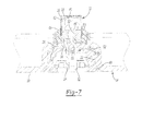
FIG. 7 is a cross-sectional view taken along line 7-7 ofFIG. 1 . - Corresponding reference numerals indicate corresponding parts throughout the several views of the drawings which are drawn to scale.
- Example embodiments will now be described more fully with reference to the accompanying drawings.
- With reference to the figures, an
inflator assembly 10 is provided and may include aninitiator assembly 12 that selectively triggers or initiates operation of theinflator assembly 10. Theinitiator assembly 12 may be received generally by and attached to aninflator base 14 and may cooperate with theinflator base 14 to dissipate electrostatic energy received by either theinflator assembly 10 orinitiator assembly 12. - The
inflator base 14 may include amain body 16 and a plurality of mounting features 18 that attach theinflator base 14 and, thus, theinflator assembly 10, to an external structure such as, for example, an airbag housing (not shown). Themain body 16 may include abottom surface 20, apocket 22, and anaperture 24 formed through abase 26 of thepocket 22. Themounting features 18 may extend from themain body 16 and may each include anaperture 28 that selectively receives a fastener (not shown) for attaching theinflator base 14 andinflator assembly 10 to an external structure such as, for example, an airbag housing or other vehicle structure (neither shown). - With particular reference to
FIGS. 4-7 , theinitiator assembly 12 is shown and may include ahousing 30, anisolated pin 32, aground pin 34, and an electrostatic-protection system 36. Thehousing 30 may include acup 38 received therein, whereby thecup 38 houses apyrotechnic material 40, acharge holder 42, afirst insulator 44, and aheader 46. Thecharge holder 42 generally surrounds thepyrotechnic material 40 and separates thepyrotechnic material 40 from thecup 38. Thefirst insulator 44 generally surrounds the isolatedpin 32 and insulates theisolated pin 32 from theheader 46. Theheader 46 surrounds thefirst insulator 44 and provides an electrical connection between theisolated pin 32 and theground pin 34 via a thin-metal connector such as, for example, a bridgewire (not shown) and a collar (not shown) that electrically couples theground pin 34 to theheader 46 at a junction of theground pin 34 and theheader 46. - As shown in
FIG. 5 , a distal end of the isolatedpin 32 is received generally within theheader 46, is insulated from theheader 46 by thefirst insulator 44, and is disposed in close proximity to thepyrotechnic material 40. Thefirst insulator 44 may include a glass seal to ensure that theisolated pin 32 is electrically isolated from theheader 46. Positioning a distal end of the isolatedpin 32 in close proximity to thepyrotechnic material 40 likewise positions the thin-metal bridgewire in close proximity to thepyrotechnic material 40. As such, when theisolated pin 32 receives sufficient electrical energy, the electrical energy is transferred from theisolated pin 32 to theground pin 34 via the bridgewire, thereby heating the bridgewire and causing ignition of thepyrotechnic material 40. Specifically, providing theisolated pin 32 with sufficient electrical energy such that the electrical energy passes from theisolated pin 32 to theground pin 34 via the bridgewire raises a temperature of the bridgewire due to the relative size of the bridgewire when compared to the largerisolated pin 32 andground pin 34. This increase in temperature of the bridgewire causes thepyrotechnic material 40 disposed within thecup 38 to ignite and release a rapid burst of energy which, in turn, triggers operation of theinflator assembly 10. - The
isolated pin 32 andground pin 34 may extend through theaperture 24 formed in theinflator base 14. Theaperture 24 may include a generally oval or slotted configuration to accommodate the side-by-side configuration of theisolated pin 32 andground pin 34. Theisolated pin 32 andground pin 34 may be insulated from theinflator base 14 proximate to theaperture 24 via afirst insulator 48 and asecond insulator 50. Thefirst insulator 48 and thesecond insulator 50 may be formed from any suitable insulating material such as, for example, nylon, and may be over molded once theinitiator assembly 12 is installed on theinflator base 14. - The
first insulator 48 may be received within thepocket 22 of theinflator base 14 and may allow passage of theisolated pin 32 andground pin 34 therethrough. Thesecond insulator 50 may be attached to thebase 26 of thepocket 22 and may at least partially surround theisolated pin 32,ground pin 34, andhousing 30 of theinitiator assembly 12 to both isolate theisolated pin 32 andground pin 34 from theinflator base 14 proximate to theopening 24 as well as to hold theisolated pin 32,ground pin 34, andhousing 30 in a desired position relative to theinflator base 14. Each of thefirst insulator 48 and thesecond insulator 50 may include a series ofprojections 52 that extend into mating recesses 54 of theinflator base 14 to attach thefirst insulator 48 and thesecond insulator 50 to theinflator base 14. - With particular reference to
FIGS. 5 and 6 , the electrostatic-protection system 36 is shown to include a printedcircuit board 56 and avaristor 58. The printedcircuit board 56 may include a pair ofapertures 60 that respectively receive theisolated pin 32 andground pin 34 and may include a series of solder lands 62. The solder lands 62 may electrically attach theisolated pin 32 andground pin 34 to the printedcircuit board 56 and may likewise be disposed generally between thevaristor 58 and the printedcircuit board 56 to attach thevaristor 58 to the printedcircuit board 56. - The printed
circuit board 56 may be received within and attached to at least a portion of thefirst insulator 48, as shown inFIGS. 5-7 . Thefirst insulator 48 may include a substantially planar surface 64 (FIG. 6 ) that abuts a top portion of the printedcircuit board 56. Thefirst insulator 48 may also include a pocket 66 (FIG. 6 ) disposed adjacent to thevaristor 58 such that a metallic or otherwise electricallyconductive surface 68 of theinflator base 14 is exposed near thevaristor 58. Thepocket 66 of thefirst insulator 48 may be formed during formation of thefirst insulator 48 by preventing the material of thefirst insulator 48 from flowing into the area of thepocket 66. When the printedcircuit board 56 is attached to theisolated pin 32 andground pin 34 such that the printedcircuit board 56 abuts theplanar surface 64 of thefirst insulator 48, thepocket 66 is positioned relative to the printedcircuit board 56 such that thevaristor 58 is received generally within thepocket 66 and opposes the electricallyconductive surface 68 of theinflator base 14. - The
varistor 58 may be a metal oxide varistor including a ceramic mass of zinc oxide grains in a matrix of other metal oxides. Thevaristor 58 may include atop surface 70 that opposes the electricallyconductive surface 68 of theinflator base 14 when the printedcircuit board 56 is attached to theisolated pin 32 and theground pin 34 and abottom surface 72 that is attached to the printedcircuit board 56 by the solder lands 62. When the printedcircuit board 56 is attached to theisolated pin 32 and theground pin 34 such that the printedcircuit board 56 abuts theplanar surface 64 of thefirst insulator 48, thetop surface 70 of thevaristor 58 is spaced apart from and opposes the electricallyconductive surface 68 of theinflator base 14. Because thefirst insulator 48 includes apocket 66 in the region of thevaristor 58, thetop surface 70 of thevaristor 58 is exposed to the electricallyconductive surface 68 of theinflator base 14. As such, a spark gap 74 (FIG. 6 ) is defined between thetop surface 70 of thevaristor 58 and the electricallyconductive surface 68 of theinflator base 14. - With particular reference to
FIGS. 5-7 , operation of theinflator assembly 10,initiator assembly 12, and electrostatic-protection system 36 will be described in detail. Under normal operation, when a signal is sent to theinitiator assembly 12 indicating that a vehicle has experienced an impact event, the electrical energy is sent to theisolated pin 32 and is transmitted to theground pin 34 via the bridgewire. This electrical energy heats the bridgewire, thereby causing thepyrotechnic material 40 disposed generally within thehousing 30 of theinitiator 12 to rapidly release heat and cause theinflator assembly 10 to rapidly generate a volume of gas and inflate an inflatable restraint (not shown). - While electrical energy is permitted to flow through the
isolated pin 32 and reach the ground wire to heat the ground wire and ignite thepyrotechnic material 40 under normal operating conditions (i.e., during an impact event, for example), should stray electrical energy be received by theisolated pin 32 orground pin 34, the electrostatic-protection system 36 serves to direct this stray electrical energy away from thepyrotechnic material 40. Directing stray electrical energy away from thepyrotechnic material 40 prevents inadvertent ignition of thepyrotechnic material 40, degradation of thepyrotechnic material 40, and/or degradation of the connection of theisolated pin 32,ground pin 34, and bridgewire to therespective components inflator assembly 10,initiator assembly 12, and/or installation of theinflator assembly 10 and/orinitiator assembly 12 into a vehicle (not shown). Such electrostatic energy may be collected on a housing of theinitiator assembly 12 such as, for example,housing 30, or may be received by either of theisolated pin 32 orground pin 34. Regardless of the source of the electrostatic energy, the energy, once received by either of theisolated pin 32 andground pin 34, may be directed away from thepyrotechnic material 40 by thevaristor 58 and/orspark gap 74. - Electrostatic energy may be dissipated by the
varistor 58 to prevent the energy from reaching thepyrotechnic material 40. For example, if theisolated pin 32 receives electrostatic energy, thevaristor 58 directs the energy to theground pin 34 and away from thepyrotechnic material 40 to prevent the energy from causing inadvertent ignition of thepyrotechnic material 40. Likewise, if the electrostatic energy is received by theground pin 34, the energy is diverted toward theisolated pin 32 and away from thepyrotechnic material 40 by thevaristor 58 to avoid inadvertent ignition of thepyrotechnic material 40. In the foregoing situations, thevaristor 58 acts as a switch, whereby energy received from one of theisolated pin 32 andground pin 34 is diverted to the other of theisolated pin 32 andground pin 34. - The
varistor 58 will act as a switch, as described above, should the electrostatic energy received by theisolated pin 32 orground pin 34 exceed a threshold voltage. In one configuration, the threshold voltage is approximately 5,000 to 6,000 volts. As such, if the voltage received by theisolated pin 32 or theground pin 34 is greater than 5,000 to 6,000 volts, thevaristor 58 transfers the voltage from theisolated pin 32 orground pin 34 to the other of theisolated pin 32 andground pin 34. However, if the voltage received by theisolated pin 32 orground pin 34 is less than the threshold voltage (i.e., less than 5,000 to 6,000 volts), the voltage arcs from thevaristor 58 to theinflator base 14 via thespark gap 74 and is dissipated by theinflator base 14. - The electrostatic energy applied to either the
isolated pin 32 orground pin 34 may arc between thevaristor 58 or the solder lands 62 to the electricallyconductive surface 68 of theinflator base 14 if the voltage applied to theisolated pin 32 orground pin 34 exceeds thespark gap 74 threshold breakdown voltage. The electrostatic energy is allowed to spark between thevaristor 58 or solder lands 62 to the electricallyconductive surface 68 of theinflator base 14 due to thepocket 66 formed in thefirst insulator 48 proximate to thevaristor 58. Note that the voltage breakdown potential (i.e., the threshold voltage) is defined by thespark gap 74 between thevaristor 58 or the solder lands 62 to the electricallyconductive surface 68 of theinflator base 14. - The
spark gap 74 may be used to control and adjust the voltage breakdown threshold. For example, if the threshold voltage is 5,000 volts, a voltage applied above 5,000 volts will arc from either thevaristor 58 or the solder lands 62 to the electricallyconductive surface 68 of theinflator base 14, as described above. This threshold voltage may be reduced from 5,000 volts if thespark gap 74 is reduced and may be increased from 5,000 volts if thespark gap 74 is increased. For example, if the distance between thetop surface 70 of thevaristor 58 is spaced apart a greater distance from the electricallyconductive surface 68 of theinflator base 14, the threshold voltage required to allow electricity to arc from either thevaristor 58 or the solder lands 62 to the electricallyconductive surface 68 of theinflator base 14 would be increased. Likewise, if thetop surface 70 of thevaristor 58 is positioned in close proximity to the electricallyconductive surface 68 of theinflator base 14, the voltage required to allow electricity to arc from thevaristor 58 or the solder lands 62 to the electricallyconductive surface 68 of theinflator base 14 is reduced. Therefore, controlling thespark gap 74 controls operation of the electrostatic-protection system 36 by dictating the threshold voltage by which electricity will arc from thevaristor 58 or the solder lands 62 to the electricallyconductive surface 68 of theinflator base 14. - The threshold voltage may be further tailored by adjusting a position of the solder lands 62 relative to the electrically
conductive surface 68 of theinflator base 14. For example, because thevaristor 58 is disposed between the solder lands 62 and the electricallyconductive surface 68 of theinflator base 14, energy received by the printedcircuit board 56 may be absorbed by thevaristor 58 such that the electricity does not arc from thevaristor 58 but, rather, arcs from the solder lands 62. - In any of the foregoing configurations, if electrostatic energy applied to either of the
isolated pin 32 orground pin 34 arcs from the printedcircuit board 56 either via thevaristor 58 or solder lands 62 to the electricallyconductive surface 68 of theinflator base 14, the applied energy is dissipated by theinflator base 14 such that the applied energy is moved away from thepyrotechnic material 40 of theinitiator assembly 12. - The foregoing description of the embodiments has been provided for purposes of illustration and description. It is not intended to be exhaustive or to limit the invention. Individual elements or features of a particular embodiment are generally not limited to that particular embodiment, but, where applicable, are interchangeable and can be used in a selected embodiment, even if not specifically shown or described. The same may also be varied in many ways. Such variations are not to be regarded as a departure from the invention, and all such modifications are intended to be included within the scope of the invention.
Claims (14)
Applications Claiming Priority (1)
| Application Number | Priority Date | Filing Date | Title |
|---|---|---|---|
| US12/482,038 US8056477B2 (en) | 2009-06-10 | 2009-06-10 | Protection system for use with airbag inflators and initiators |
Publications (3)
| Publication Number | Publication Date |
|---|---|
| EP2261091A2 true EP2261091A2 (en) | 2010-12-15 |
| EP2261091A3 EP2261091A3 (en) | 2012-03-14 |
| EP2261091B1 EP2261091B1 (en) | 2013-10-16 |
Family
ID=42668806
Family Applications (1)
| Application Number | Title | Priority Date | Filing Date |
|---|---|---|---|
| EP10164432.6A Not-in-force EP2261091B1 (en) | 2009-06-10 | 2010-05-31 | Protection system for use with airbag inflators and initiators |
Country Status (4)
| Country | Link |
|---|---|
| US (1) | US8056477B2 (en) |
| EP (1) | EP2261091B1 (en) |
| JP (1) | JP5220061B2 (en) |
| CN (1) | CN101920688B (en) |
Cited By (1)
| Publication number | Priority date | Publication date | Assignee | Title |
|---|---|---|---|---|
| WO2016113123A1 (en) * | 2015-01-13 | 2016-07-21 | Wabco Gmbh | Sensor unit with an electric connection of the sensor housing for discharging an electrostatic charge of a motor vehicle |
Families Citing this family (5)
| Publication number | Priority date | Publication date | Assignee | Title |
|---|---|---|---|---|
| EP2157399A4 (en) * | 2007-06-13 | 2013-03-20 | Nippon Kayaku Kk | Squib, gas generation device for airbag, and gas generation device for seatbelt pretensioner |
| JP5897417B2 (en) * | 2012-07-13 | 2016-03-30 | 株式会社ダイセル | Cover member for igniter |
| US9939235B2 (en) * | 2013-10-09 | 2018-04-10 | Battelle Energy Alliance, Llc | Initiation devices, initiation systems including initiation devices and related methods |
| US9440615B2 (en) | 2014-12-10 | 2016-09-13 | Autoliv Asp, Inc. | Initiator assemblies |
| JP7284044B2 (en) * | 2019-08-30 | 2023-05-30 | 株式会社ダイセル | Ignitor holding structure |
Family Cites Families (39)
| Publication number | Priority date | Publication date | Assignee | Title |
|---|---|---|---|---|
| US1605688A (en) * | 1924-06-20 | 1926-11-02 | Western Cartridge Co | Method of making detonators |
| US2956211A (en) * | 1958-05-19 | 1960-10-11 | Gulf Oil Corp | Firing apparatus for explosives |
| US3450414A (en) * | 1965-11-06 | 1969-06-17 | Gic Kk | Safety device for vehicle passengers |
| US3640224A (en) * | 1969-09-12 | 1972-02-08 | Us Navy | Rf immune firing circuit employing high-impedance leads |
| JPS5135931A (en) * | 1974-09-19 | 1976-03-26 | Toyota Motor Co Ltd | Gasuhatsuseiki no tenkakairo |
| US4306499A (en) * | 1978-04-03 | 1981-12-22 | Thiokol Corporation | Electric safety squib |
| US4422381A (en) * | 1979-11-20 | 1983-12-27 | Ici Americas Inc. | Igniter with static discharge element and ferrite sleeve |
| US4530516A (en) | 1984-07-09 | 1985-07-23 | Morton Thiokol Inc. | Aluminum inflator with steel center-tie |
| US4708060A (en) * | 1985-02-19 | 1987-11-24 | The United States Of America As Represented By The United States Department Of Energy | Semiconductor bridge (SCB) igniter |
| EP0200946A1 (en) | 1985-04-30 | 1986-11-12 | BBC Brown Boveri AG | Protective device for a user connected to the power supply line of an electrical power system |
| US5057041A (en) | 1990-06-29 | 1991-10-15 | Foxconn International | User configurable integrated electrical connector assembly |
| US5928839A (en) | 1992-05-15 | 1999-07-27 | Morton International, Inc. | Method of forming a multilayer printed circuit board and product thereof |
| CA2103510A1 (en) | 1992-09-11 | 1994-03-12 | Morton International Inc. | Printed circuit bridge for an airbag inflator |
| US5406889A (en) | 1993-09-03 | 1995-04-18 | Morton International, Inc. | Direct laser ignition of ignition products |
| US5531473A (en) | 1994-05-31 | 1996-07-02 | Morton International, Inc. | Fluid fuel-containing initiator device for an air bag inflator |
| US5616881A (en) * | 1995-05-30 | 1997-04-01 | Morton International, Inc. | Inflator socket pin collar for integrated circuit initaitor with integral metal oxide varistor for electro-static discharge protections |
| US5668345A (en) | 1995-10-19 | 1997-09-16 | Morton International, Inc. | Airbag inflators employing coated porous substrates |
| US5672841A (en) | 1995-12-15 | 1997-09-30 | Morton International, Inc. | Inflator initiator with zener diode electrostatic discharge protection |
| US5932832A (en) * | 1996-04-15 | 1999-08-03 | Autoliv Asp, Inc. | High pressure resistant initiator with integral metal oxide varistor for electro-static discharge protection |
| US6098548A (en) | 1997-03-05 | 2000-08-08 | Autoliv Asp, Inc. | Non-pyrotechnic initiator |
| US6070531A (en) * | 1997-07-22 | 2000-06-06 | Autoliv Asp, Inc. | Application specific integrated circuit package and initiator employing same |
| FR2788846B1 (en) * | 1999-01-25 | 2001-10-26 | Livbag Snc | HYBRID GAS GENERATOR WITH PROFILE EXPLOSIVE LOADING INITIATOR |
| JP2000292100A (en) * | 1999-04-09 | 2000-10-20 | Showa Kinzoku Kogyo Kk | Electric ignition type gas generator |
| US6220263B1 (en) | 1999-12-29 | 2001-04-24 | William J. Weiner | Portable protective enclosure for a vehicle |
| EP1148602B1 (en) * | 2000-04-20 | 2003-11-26 | Siemens Aktiengesellschaft | Overvoltage arrester device |
| US6527297B1 (en) | 2000-08-30 | 2003-03-04 | Autoliv Asp, Inc. | Inflator device ignition of gas generant |
| US6467414B1 (en) * | 2001-06-29 | 2002-10-22 | Breed Automotive Technology, Inc. | Ignitor with printed electrostatic discharge spark gap |
| US6699076B2 (en) | 2001-10-09 | 2004-03-02 | Siemens Vdo Automotive Corporation | Connector assembly with metal oxide varistor |
| JP2003205823A (en) * | 2002-01-16 | 2003-07-22 | Showa Kinzoku Kogyo Kk | Gas generator |
| BRPI0311647A2 (en) | 2002-06-07 | 2016-06-28 | Autoliv Dev | electrically insulated mounting arrangement for an air bag module |
| US6979022B2 (en) | 2003-05-23 | 2005-12-27 | Autoliv Asp, Inc. | Flexible inflator with co-extruded propellant and moisture barrier |
| US6941868B2 (en) | 2003-06-26 | 2005-09-13 | Autoliv Asp, Inc. | Single increment initiator charge |
| US7343859B2 (en) | 2003-11-10 | 2008-03-18 | Honda Motor Co., Ltd. | Squib |
| US7055854B2 (en) * | 2004-03-03 | 2006-06-06 | Autoliv Asp, Inc. | Snap-in castanet airbag module for a vehicular steering wheel |
| US7316187B2 (en) * | 2004-09-17 | 2008-01-08 | Autoliv Asp, Inc. | Radial discharge actuator device |
| FR2875594B1 (en) | 2004-09-21 | 2007-03-16 | Ncs Pyrotechnie & Tech | ELECTRO-PYROTECHNIC INITIATOR |
| DE102004060734B4 (en) | 2004-12-15 | 2008-10-16 | Amphenol-Tuchel Electronics Gmbh | Contact protection for connectors with protective device against interference |
| FR2893191B1 (en) | 2005-11-09 | 2008-02-01 | Ncs Pyrotechnie & Tech | GLASS-METAL TRAVERSEE, ITS MANUFACTURING METHOD AND ELECTRO-PYROTECHNIC INITIATOR. |
| JP4668889B2 (en) * | 2006-12-01 | 2011-04-13 | 日本化薬株式会社 | Ignition element mounted capacitor, header assembly, squib, gas generator for airbag and gas generator for seat belt pretensioner |
-
2009
- 2009-06-10 US US12/482,038 patent/US8056477B2/en not_active Expired - Fee Related
-
2010
- 2010-05-31 EP EP10164432.6A patent/EP2261091B1/en not_active Not-in-force
- 2010-06-04 CN CN2010101982589A patent/CN101920688B/en not_active Expired - Fee Related
- 2010-06-07 JP JP2010129625A patent/JP5220061B2/en not_active Expired - Fee Related
Non-Patent Citations (1)
| Title |
|---|
| None |
Cited By (2)
| Publication number | Priority date | Publication date | Assignee | Title |
|---|---|---|---|---|
| WO2016113123A1 (en) * | 2015-01-13 | 2016-07-21 | Wabco Gmbh | Sensor unit with an electric connection of the sensor housing for discharging an electrostatic charge of a motor vehicle |
| US10393545B2 (en) | 2015-01-13 | 2019-08-27 | Wabco Gmbh | Sensor unit, sensing and analysis device with such a sensor unit and motor vehicle or trailer therewith and method for protecting an analyzer |
Also Published As
| Publication number | Publication date |
|---|---|
| JP5220061B2 (en) | 2013-06-26 |
| CN101920688A (en) | 2010-12-22 |
| CN101920688B (en) | 2013-03-27 |
| US20100313783A1 (en) | 2010-12-16 |
| EP2261091A3 (en) | 2012-03-14 |
| JP2011016515A (en) | 2011-01-27 |
| EP2261091B1 (en) | 2013-10-16 |
| US8056477B2 (en) | 2011-11-15 |
Similar Documents
| Publication | Publication Date | Title |
|---|---|---|
| EP2261091B1 (en) | Protection system for use with airbag inflators and initiators | |
| EP0779492B1 (en) | Inflator initiator with zener diode electrostatic discharge protector | |
| EP0802092A1 (en) | High pressure resistant initiator with integral metal oxide varistor for electro-static discharge protection | |
| EP1257440B1 (en) | Initiator assembly with activation circuitry | |
| JP2700100B2 (en) | Igniter | |
| US6289813B1 (en) | Electropyrotechnic igniter with enhanced ignition reliability | |
| KR100475778B1 (en) | Electropyrotechnic igniter with two ignition heads and use in motor vehicle safety | |
| US4306499A (en) | Electric safety squib | |
| US6220163B1 (en) | Electro-pyrotechnic initiation system protected against electrostatic discharges | |
| US5616881A (en) | Inflator socket pin collar for integrated circuit initaitor with integral metal oxide varistor for electro-static discharge protections | |
| CA2298710A1 (en) | Ignition unit for a passenger protection device of a motor vehicle | |
| KR20010111094A (en) | Igniter | |
| JPS6233516B2 (en) | ||
| EP1035400B1 (en) | Pretensioner with a link earthing the igniter housing | |
| SE445489B (en) | ELECTRICALLY ACTIVABLE EXPLOSION Capsule | |
| US6732655B1 (en) | Ignition device for restraint means in a vehicle | |
| WO1998002711A1 (en) | Electro-explosive device | |
| JP4397731B2 (en) | Ignition device | |
| CN118786502A (en) | Circuit switching device | |
| US20230023676A1 (en) | Electrical transmission device and motor vehicle | |
| WO2000073729A1 (en) | Igniter, header assembly, and igniter plug | |
| JP2005174588A (en) | High sensitivity fuse | |
| HK1028100B (en) | Ignition unit for a passenger protection device of a motor vehicle |
Legal Events
| Date | Code | Title | Description |
|---|---|---|---|
| PUAI | Public reference made under article 153(3) epc to a published international application that has entered the european phase |
Free format text: ORIGINAL CODE: 0009012 |
|
| AK | Designated contracting states |
Kind code of ref document: A2 Designated state(s): AL AT BE BG CH CY CZ DE DK EE ES FI FR GB GR HR HU IE IS IT LI LT LU LV MC MK MT NL NO PL PT RO SE SI SK SM TR |
|
| AX | Request for extension of the european patent |
Extension state: BA ME RS |
|
| PUAL | Search report despatched |
Free format text: ORIGINAL CODE: 0009013 |
|
| AK | Designated contracting states |
Kind code of ref document: A3 Designated state(s): AL AT BE BG CH CY CZ DE DK EE ES FI FR GB GR HR HU IE IS IT LI LT LU LV MC MK MT NL NO PL PT RO SE SI SK SM TR |
|
| AX | Request for extension of the european patent |
Extension state: BA ME RS |
|
| RIC1 | Information provided on ipc code assigned before grant |
Ipc: B60R 21/26 20110101AFI20120208BHEP |
|
| 17P | Request for examination filed |
Effective date: 20120910 |
|
| GRAP | Despatch of communication of intention to grant a patent |
Free format text: ORIGINAL CODE: EPIDOSNIGR1 |
|
| INTG | Intention to grant announced |
Effective date: 20130523 |
|
| GRAS | Grant fee paid |
Free format text: ORIGINAL CODE: EPIDOSNIGR3 |
|
| GRAA | (expected) grant |
Free format text: ORIGINAL CODE: 0009210 |
|
| AK | Designated contracting states |
Kind code of ref document: B1 Designated state(s): AL AT BE BG CH CY CZ DE DK EE ES FI FR GB GR HR HU IE IS IT LI LT LU LV MC MK MT NL NO PL PT RO SE SI SK SM TR |
|
| REG | Reference to a national code |
Ref country code: GB Ref legal event code: FG4D |
|
| REG | Reference to a national code |
Ref country code: CH Ref legal event code: EP |
|
| REG | Reference to a national code |
Ref country code: IE Ref legal event code: FG4D |
|
| REG | Reference to a national code |
Ref country code: AT Ref legal event code: REF Ref document number: 636324 Country of ref document: AT Kind code of ref document: T Effective date: 20131115 |
|
| REG | Reference to a national code |
Ref country code: DE Ref legal event code: R096 Ref document number: 602010010920 Country of ref document: DE Effective date: 20131212 |
|
| REG | Reference to a national code |
Ref country code: NL Ref legal event code: VDEP Effective date: 20131016 |
|
| REG | Reference to a national code |
Ref country code: AT Ref legal event code: MK05 Ref document number: 636324 Country of ref document: AT Kind code of ref document: T Effective date: 20131016 |
|
| REG | Reference to a national code |
Ref country code: LT Ref legal event code: MG4D |
|
| PG25 | Lapsed in a contracting state [announced via postgrant information from national office to epo] |
Ref country code: NO Free format text: LAPSE BECAUSE OF FAILURE TO SUBMIT A TRANSLATION OF THE DESCRIPTION OR TO PAY THE FEE WITHIN THE PRESCRIBED TIME-LIMIT Effective date: 20140116 Ref country code: HR Free format text: LAPSE BECAUSE OF FAILURE TO SUBMIT A TRANSLATION OF THE DESCRIPTION OR TO PAY THE FEE WITHIN THE PRESCRIBED TIME-LIMIT Effective date: 20131016 Ref country code: LT Free format text: LAPSE BECAUSE OF FAILURE TO SUBMIT A TRANSLATION OF THE DESCRIPTION OR TO PAY THE FEE WITHIN THE PRESCRIBED TIME-LIMIT Effective date: 20131016 Ref country code: NL Free format text: LAPSE BECAUSE OF FAILURE TO SUBMIT A TRANSLATION OF THE DESCRIPTION OR TO PAY THE FEE WITHIN THE PRESCRIBED TIME-LIMIT Effective date: 20131016 Ref country code: FI Free format text: LAPSE BECAUSE OF FAILURE TO SUBMIT A TRANSLATION OF THE DESCRIPTION OR TO PAY THE FEE WITHIN THE PRESCRIBED TIME-LIMIT Effective date: 20131016 Ref country code: IS Free format text: LAPSE BECAUSE OF FAILURE TO SUBMIT A TRANSLATION OF THE DESCRIPTION OR TO PAY THE FEE WITHIN THE PRESCRIBED TIME-LIMIT Effective date: 20140216 Ref country code: BE Free format text: LAPSE BECAUSE OF FAILURE TO SUBMIT A TRANSLATION OF THE DESCRIPTION OR TO PAY THE FEE WITHIN THE PRESCRIBED TIME-LIMIT Effective date: 20131016 Ref country code: SE Free format text: LAPSE BECAUSE OF FAILURE TO SUBMIT A TRANSLATION OF THE DESCRIPTION OR TO PAY THE FEE WITHIN THE PRESCRIBED TIME-LIMIT Effective date: 20131016 |
|
| PG25 | Lapsed in a contracting state [announced via postgrant information from national office to epo] |
Ref country code: LV Free format text: LAPSE BECAUSE OF FAILURE TO SUBMIT A TRANSLATION OF THE DESCRIPTION OR TO PAY THE FEE WITHIN THE PRESCRIBED TIME-LIMIT Effective date: 20131016 Ref country code: ES Free format text: LAPSE BECAUSE OF FAILURE TO SUBMIT A TRANSLATION OF THE DESCRIPTION OR TO PAY THE FEE WITHIN THE PRESCRIBED TIME-LIMIT Effective date: 20131016 Ref country code: AT Free format text: LAPSE BECAUSE OF FAILURE TO SUBMIT A TRANSLATION OF THE DESCRIPTION OR TO PAY THE FEE WITHIN THE PRESCRIBED TIME-LIMIT Effective date: 20131016 Ref country code: CY Free format text: LAPSE BECAUSE OF FAILURE TO SUBMIT A TRANSLATION OF THE DESCRIPTION OR TO PAY THE FEE WITHIN THE PRESCRIBED TIME-LIMIT Effective date: 20131016 |
|
| PG25 | Lapsed in a contracting state [announced via postgrant information from national office to epo] |
Ref country code: PT Free format text: LAPSE BECAUSE OF FAILURE TO SUBMIT A TRANSLATION OF THE DESCRIPTION OR TO PAY THE FEE WITHIN THE PRESCRIBED TIME-LIMIT Effective date: 20140217 |
|
| REG | Reference to a national code |
Ref country code: DE Ref legal event code: R097 Ref document number: 602010010920 Country of ref document: DE |
|
| PG25 | Lapsed in a contracting state [announced via postgrant information from national office to epo] |
Ref country code: EE Free format text: LAPSE BECAUSE OF FAILURE TO SUBMIT A TRANSLATION OF THE DESCRIPTION OR TO PAY THE FEE WITHIN THE PRESCRIBED TIME-LIMIT Effective date: 20131016 |
|
| PLBE | No opposition filed within time limit |
Free format text: ORIGINAL CODE: 0009261 |
|
| STAA | Information on the status of an ep patent application or granted ep patent |
Free format text: STATUS: NO OPPOSITION FILED WITHIN TIME LIMIT |
|
| PG25 | Lapsed in a contracting state [announced via postgrant information from national office to epo] |
Ref country code: CZ Free format text: LAPSE BECAUSE OF FAILURE TO SUBMIT A TRANSLATION OF THE DESCRIPTION OR TO PAY THE FEE WITHIN THE PRESCRIBED TIME-LIMIT Effective date: 20131016 Ref country code: IT Free format text: LAPSE BECAUSE OF FAILURE TO SUBMIT A TRANSLATION OF THE DESCRIPTION OR TO PAY THE FEE WITHIN THE PRESCRIBED TIME-LIMIT Effective date: 20131016 Ref country code: PL Free format text: LAPSE BECAUSE OF FAILURE TO SUBMIT A TRANSLATION OF THE DESCRIPTION OR TO PAY THE FEE WITHIN THE PRESCRIBED TIME-LIMIT Effective date: 20131016 Ref country code: RO Free format text: LAPSE BECAUSE OF FAILURE TO SUBMIT A TRANSLATION OF THE DESCRIPTION OR TO PAY THE FEE WITHIN THE PRESCRIBED TIME-LIMIT Effective date: 20131016 Ref country code: SK Free format text: LAPSE BECAUSE OF FAILURE TO SUBMIT A TRANSLATION OF THE DESCRIPTION OR TO PAY THE FEE WITHIN THE PRESCRIBED TIME-LIMIT Effective date: 20131016 |
|
| 26N | No opposition filed |
Effective date: 20140717 |
|
| PG25 | Lapsed in a contracting state [announced via postgrant information from national office to epo] |
Ref country code: DK Free format text: LAPSE BECAUSE OF FAILURE TO SUBMIT A TRANSLATION OF THE DESCRIPTION OR TO PAY THE FEE WITHIN THE PRESCRIBED TIME-LIMIT Effective date: 20131016 |
|
| REG | Reference to a national code |
Ref country code: DE Ref legal event code: R097 Ref document number: 602010010920 Country of ref document: DE Effective date: 20140717 |
|
| PG25 | Lapsed in a contracting state [announced via postgrant information from national office to epo] |
Ref country code: LU Free format text: LAPSE BECAUSE OF FAILURE TO SUBMIT A TRANSLATION OF THE DESCRIPTION OR TO PAY THE FEE WITHIN THE PRESCRIBED TIME-LIMIT Effective date: 20140531 |
|
| REG | Reference to a national code |
Ref country code: CH Ref legal event code: PL |
|
| GBPC | Gb: european patent ceased through non-payment of renewal fee |
Effective date: 20140531 |
|
| PG25 | Lapsed in a contracting state [announced via postgrant information from national office to epo] |
Ref country code: MC Free format text: LAPSE BECAUSE OF FAILURE TO SUBMIT A TRANSLATION OF THE DESCRIPTION OR TO PAY THE FEE WITHIN THE PRESCRIBED TIME-LIMIT Effective date: 20131016 Ref country code: CH Free format text: LAPSE BECAUSE OF NON-PAYMENT OF DUE FEES Effective date: 20140531 Ref country code: LI Free format text: LAPSE BECAUSE OF NON-PAYMENT OF DUE FEES Effective date: 20140531 |
|
| REG | Reference to a national code |
Ref country code: IE Ref legal event code: MM4A |
|
| PG25 | Lapsed in a contracting state [announced via postgrant information from national office to epo] |
Ref country code: SI Free format text: LAPSE BECAUSE OF FAILURE TO SUBMIT A TRANSLATION OF THE DESCRIPTION OR TO PAY THE FEE WITHIN THE PRESCRIBED TIME-LIMIT Effective date: 20131016 |
|
| REG | Reference to a national code |
Ref country code: FR Ref legal event code: PLFP Year of fee payment: 6 |
|
| PG25 | Lapsed in a contracting state [announced via postgrant information from national office to epo] |
Ref country code: IE Free format text: LAPSE BECAUSE OF NON-PAYMENT OF DUE FEES Effective date: 20140531 |
|
| PG25 | Lapsed in a contracting state [announced via postgrant information from national office to epo] |
Ref country code: GB Free format text: LAPSE BECAUSE OF NON-PAYMENT OF DUE FEES Effective date: 20140531 |
|
| PGFP | Annual fee paid to national office [announced via postgrant information from national office to epo] |
Ref country code: DE Payment date: 20150306 Year of fee payment: 6 |
|
| PGFP | Annual fee paid to national office [announced via postgrant information from national office to epo] |
Ref country code: FR Payment date: 20150330 Year of fee payment: 6 |
|
| PG25 | Lapsed in a contracting state [announced via postgrant information from national office to epo] |
Ref country code: MT Free format text: LAPSE BECAUSE OF FAILURE TO SUBMIT A TRANSLATION OF THE DESCRIPTION OR TO PAY THE FEE WITHIN THE PRESCRIBED TIME-LIMIT Effective date: 20131016 |
|
| PG25 | Lapsed in a contracting state [announced via postgrant information from national office to epo] |
Ref country code: SM Free format text: LAPSE BECAUSE OF FAILURE TO SUBMIT A TRANSLATION OF THE DESCRIPTION OR TO PAY THE FEE WITHIN THE PRESCRIBED TIME-LIMIT Effective date: 20131016 |
|
| PG25 | Lapsed in a contracting state [announced via postgrant information from national office to epo] |
Ref country code: BG Free format text: LAPSE BECAUSE OF FAILURE TO SUBMIT A TRANSLATION OF THE DESCRIPTION OR TO PAY THE FEE WITHIN THE PRESCRIBED TIME-LIMIT Effective date: 20131016 Ref country code: GR Free format text: LAPSE BECAUSE OF FAILURE TO SUBMIT A TRANSLATION OF THE DESCRIPTION OR TO PAY THE FEE WITHIN THE PRESCRIBED TIME-LIMIT Effective date: 20140117 |
|
| PG25 | Lapsed in a contracting state [announced via postgrant information from national office to epo] |
Ref country code: HU Free format text: LAPSE BECAUSE OF FAILURE TO SUBMIT A TRANSLATION OF THE DESCRIPTION OR TO PAY THE FEE WITHIN THE PRESCRIBED TIME-LIMIT; INVALID AB INITIO Effective date: 20100531 Ref country code: TR Free format text: LAPSE BECAUSE OF FAILURE TO SUBMIT A TRANSLATION OF THE DESCRIPTION OR TO PAY THE FEE WITHIN THE PRESCRIBED TIME-LIMIT Effective date: 20131016 |
|
| REG | Reference to a national code |
Ref country code: DE Ref legal event code: R119 Ref document number: 602010010920 Country of ref document: DE |
|
| REG | Reference to a national code |
Ref country code: FR Ref legal event code: ST Effective date: 20170131 |
|
| PG25 | Lapsed in a contracting state [announced via postgrant information from national office to epo] |
Ref country code: FR Free format text: LAPSE BECAUSE OF NON-PAYMENT OF DUE FEES Effective date: 20160531 Ref country code: DE Free format text: LAPSE BECAUSE OF NON-PAYMENT OF DUE FEES Effective date: 20161201 |
|
| PG25 | Lapsed in a contracting state [announced via postgrant information from national office to epo] |
Ref country code: MK Free format text: LAPSE BECAUSE OF FAILURE TO SUBMIT A TRANSLATION OF THE DESCRIPTION OR TO PAY THE FEE WITHIN THE PRESCRIBED TIME-LIMIT Effective date: 20131016 |
|
| PG25 | Lapsed in a contracting state [announced via postgrant information from national office to epo] |
Ref country code: AL Free format text: LAPSE BECAUSE OF FAILURE TO SUBMIT A TRANSLATION OF THE DESCRIPTION OR TO PAY THE FEE WITHIN THE PRESCRIBED TIME-LIMIT Effective date: 20131016 |