EP2260928A1 - Membrane separation apparatus and membrane cassette - Google Patents
Membrane separation apparatus and membrane cassette Download PDFInfo
- Publication number
- EP2260928A1 EP2260928A1 EP08720634A EP08720634A EP2260928A1 EP 2260928 A1 EP2260928 A1 EP 2260928A1 EP 08720634 A EP08720634 A EP 08720634A EP 08720634 A EP08720634 A EP 08720634A EP 2260928 A1 EP2260928 A1 EP 2260928A1
- Authority
- EP
- European Patent Office
- Prior art keywords
- membrane
- water collecting
- filtration
- elements
- membrane elements
- Prior art date
- Legal status (The legal status is an assumption and is not a legal conclusion. Google has not performed a legal analysis and makes no representation as to the accuracy of the status listed.)
- Granted
Links
Images





Classifications
-
- B—PERFORMING OPERATIONS; TRANSPORTING
- B01—PHYSICAL OR CHEMICAL PROCESSES OR APPARATUS IN GENERAL
- B01D—SEPARATION
- B01D63/00—Apparatus in general for separation processes using semi-permeable membranes
- B01D63/08—Flat membrane modules
- B01D63/082—Flat membrane modules comprising a stack of flat membranes
- B01D63/0821—Membrane plate arrangements for submerged operation
-
- B—PERFORMING OPERATIONS; TRANSPORTING
- B01—PHYSICAL OR CHEMICAL PROCESSES OR APPARATUS IN GENERAL
- B01D—SEPARATION
- B01D61/00—Processes of separation using semi-permeable membranes, e.g. dialysis, osmosis or ultrafiltration; Apparatus, accessories or auxiliary operations specially adapted therefor
- B01D61/14—Ultrafiltration; Microfiltration
- B01D61/18—Apparatus therefor
-
- B—PERFORMING OPERATIONS; TRANSPORTING
- B01—PHYSICAL OR CHEMICAL PROCESSES OR APPARATUS IN GENERAL
- B01D—SEPARATION
- B01D61/00—Processes of separation using semi-permeable membranes, e.g. dialysis, osmosis or ultrafiltration; Apparatus, accessories or auxiliary operations specially adapted therefor
- B01D61/14—Ultrafiltration; Microfiltration
- B01D61/20—Accessories; Auxiliary operations
-
- B—PERFORMING OPERATIONS; TRANSPORTING
- B01—PHYSICAL OR CHEMICAL PROCESSES OR APPARATUS IN GENERAL
- B01D—SEPARATION
- B01D65/00—Accessories or auxiliary operations, in general, for separation processes or apparatus using semi-permeable membranes
-
- B—PERFORMING OPERATIONS; TRANSPORTING
- B01—PHYSICAL OR CHEMICAL PROCESSES OR APPARATUS IN GENERAL
- B01D—SEPARATION
- B01D2313/00—Details relating to membrane modules or apparatus
- B01D2313/12—Specific discharge elements
-
- B—PERFORMING OPERATIONS; TRANSPORTING
- B01—PHYSICAL OR CHEMICAL PROCESSES OR APPARATUS IN GENERAL
- B01D—SEPARATION
- B01D2313/00—Details relating to membrane modules or apparatus
- B01D2313/21—Specific headers, end caps
-
- B—PERFORMING OPERATIONS; TRANSPORTING
- B01—PHYSICAL OR CHEMICAL PROCESSES OR APPARATUS IN GENERAL
- B01D—SEPARATION
- B01D2315/00—Details relating to the membrane module operation
- B01D2315/06—Submerged-type; Immersion type
-
- C—CHEMISTRY; METALLURGY
- C02—TREATMENT OF WATER, WASTE WATER, SEWAGE, OR SLUDGE
- C02F—TREATMENT OF WATER, WASTE WATER, SEWAGE, OR SLUDGE
- C02F1/00—Treatment of water, waste water, or sewage
- C02F1/44—Treatment of water, waste water, or sewage by dialysis, osmosis or reverse osmosis
Definitions
- the present invention relates to a membrane separator and a membrane cassette used for filtration or concentration in the water treatment of tap water, wastewater and the like, and to the water collecting case structure of the membrane separator and the membrane cassette.
- a submerged membrane filtration apparatus having a plurality of membrane elements arranged in parallel at appropriate intervals is known.
- two flat membranes are stacked via a spacer, the two flat membranes are welded or bonded end to end on both sides of the two flat membranes to form a filtration membrane member, and filtration water collecting portions provided on the sides of the filtration membrane member communicate with the inside of the filtration membrane member.
- a separator unit is mounted with filtration membranes on both surfaces of a water passing material having a water passing function, the membrane ends of the filtration membranes are joined to the water passing material with joining members, hollow portions are formed in the joining members, and suction pipes provided in the hollow portions of the joining members communicate with the channel of the water passing material.
- FIGS. 18 to 19 The conceptual model of such a membrane separator is shown in FIGS. 18 to 19 .
- a plurality of membrane elements 1 are arranged in parallel and channels 2 are formed along the flowing direction of a liquid to be treated between the membrane elements 1.
- the membrane elements 1 are formed by arranging filtration membranes on the surfaces of membrane supporting members and have permeate channels between the membrane supporting members and the filtration membranes.
- Water collecting cases 3 arranged on both sides of the membrane elements 1 have opening portions communicating with water collecting spaces 4 in the water collecting cases 3.
- the sides of the membrane elements 1 inserted in the opening portions are held water-tight by sealing materials.
- the permeate channels of the membrane elements 1 communicate with the water collecting spaces 4 of the water collecting cases 3.
- the lower membrane separator receives, through the water collecting cases 3, the load of the upper membrane separator. Therefore, the load applied to the water collecting cases 3 increases towards the lower membrane separator.
- the water collecting cases 3 are required to have strength enough to withstand the load.
- the water collecting cases 3 are formed only of thin tabular wall members forming the outer walls of the water collecting cases 3, and receive the load, the internal pressure, and the external pressure only through the peripheral wall members, the withstand load of the water collecting cases 3 is structurally small.
- the ribs 5 when ribs 5 are arranged inside the water collecting cases 3 to reinforce the water collecting cases 3, the ribs 5 constitute a factor that prevents the flow of the permeate in the water collecting spaces 4 of the water collecting cases 3.
- the ribs 5 When the ribs 5 are arranged on the outside of the water collecting cases 3, the ribs 5 constitute a factor that prevents the flow of the liquid to be treated in the treatment tank and the external dimension of the membrane separator increases.
- the permeate simultaneously flows into the water collecting spaces 4 of the water collecting cases 3 from the respective membrane elements 1. Since the permeate in the water collecting cases 3 flows through water collecting ports 6 to the outside, the permeate flowing in from the respective membrane elements 1 meets together as it approaches the water collecting ports 6. In other words, for the permeate flowing from the membrane elements 1 distant from the water collecting ports 6 toward the water collecting ports 6, the permeate flowing from the membrane elements 1 close to the water collecting ports 6 into the water collecting spaces 4 acts as a channel resistance.
- This channel resistance increases as the distance of the membrane elements 1 from the water collecting ports 6 increases, and constitutes a factor that prevents the permeate from flowing into the water collecting spaces 4 from the membrane elements 1. Therefore, the flow rate of the permeate flowing through the membrane elements 1 varies between the membrane elements 1.
- the present invention solves the problems and it is an object of the present invention to provide a membrane separator and a membrane cassette that can secure sufficient strength in water collecting cases and realize a smooth flow of permeate in water collecting spaces.
- a membrane separator includes: a plurality of membrane elements arranged in parallel to form channels for a liquid to be treated between the membrane elements; and a water collecting case which keeps water-tight the sides of the membrane elements along the channels for the liquid to be treated, and has therein a water collecting space with which the permeate channels of the membrane elements communicate.
- a water collecting case out of wall members arranged to surround the water collecting space, at least the wall member opposed to the sides of the membrane elements forms a projecting portion projecting to the outer side and recessed portions recessed to the inner side.
- the wall member opposed to the sides of the membrane elements forms the projecting portion projecting to the outer side, forms an expanded area in the water collecting space, and has a water collecting port opened so as to face the expanded area.
- the water collecting case has ribs on the outer sides of the wall members surrounding the water collecting space, and the ribs are shaped so as to fit within the overall length dimension of the membrane separator along an inter-water collecting case direction.
- a membrane cassette according to the present invention uses the membrane separator.
- a plurality of the membrane separators are vertically stacked in multiple stages along the flowing direction of a liquid to be treated.
- the upper and lower membrane separators communicate with each other via water collecting ports that constitute coupling portions formed on the wall surfaces opposed to each other of the water collecting cases of the membrane separators.
- the wall member opposed to the sides of the membrane elements forms the projecting portion projecting to the outer side and the recessed portions recessed to the inner side, the buckling load of the wall member increases. Therefore, in the present invention, when a water collecting space having the same capacity as that of the water collecting case in the conventional configuration is provided, it is possible to realize a water collecting case with increased strength.
- the wall member opposed to the sides of the membrane elements forms the projecting portion projecting to the outer side, forms the expanded area in the water collecting space, and has the water collecting port opened so as to face the expanded area, a channel around the water collecting port is widened. Therefore, even if permeate flowing in from the respective membrane elements meets together and flows toward the water collecting port, it is possible to suppress an increase in channel resistance near the water collecting port and contribute to the equalization of flow rate of the permeate flowing through the respective membrane elements.
- the ribs are arranged outside the wall members and within the overall length dimension of the membrane separator along the direction in which the water collecting cases are arranged, the ribs do not constitute a factor that prevents the flow of the liquid to be treated, the external dimension of the membrane separator is not increased, and it is possible to increase the strength of the water collecting case.
- a membrane cassette 11 of a membrane separator includes a plurality of vertically-stacked membrane modules 12.
- the membrane cassette 11 is immersed and set in a liquid to be treated in a treatment tank (not shown).
- an air diffuser 11a is arranged below the lower membrane module 12.
- the membrane separator can be formed of a single membrane module.
- a plurality of membrane elements 13 are arranged in parallel at predetermined intervals. Channels for a liquid to be treated are formed in a vertical direction between the membrane elements 13. Both sides of the membrane elements 13 along the flow of the liquid to be treated are water-tightly sealed to water collecting cases 14.
- Each of the water collecting cases 14 is hollow-shaped and has a water collecting space therein. However, the water collecting case 14 can be provided only on one side of the membrane element 13. In this case, the other side of the membrane element 13 is sealed by resin or the like explained later.
- the membrane elements 13 are arranged in the up-to-down direction.
- the arrangement direction of the membrane elements 13 is not limited to the up-to-down direction.
- the membrane elements 13 only have to be arranged along the flowing direction of the liquid to be treated. It is also possible to arrange the membrane elements 13 in the horizontal direction or obliquely.
- the membrane module 12 includes upper coupling portions 23 provided on the upper end faces of the water collecting cases 14 and lower coupling portions 24 provided on the lower end faces thereof.
- the upper coupling portions 23 and the lower coupling portions 24 form water collecting ports and communicate with water collecting spaces 14a of the water collecting cases 14.
- the lower coupling portions 24 of the upper membrane module 12 and the upper coupling portions 23 of the lower membrane module 12 are coupled to each other.
- the upper coupling portions 23 of the water collecting cases 14 in the upper membrane module 12 communicate with water collecting pipes 26 via tubes 25.
- the lower coupling portions 24 of the lower membrane module 12 are closed by plugs (not shown).
- plugs not shown
- Extraction of permeate only has to be performed from at least one portion of the left and right upper coupling portions 23 in the upper membrane module 12 and the left and right lower coupling portions 24 in the lower membrane module 12.
- each of the water collecting cases 14 the plurality of membrane elements 13 are held water-tight via a sealing material (resin, etc.) 16 potted in an opening portion 15.
- the water collecting case 14 is not limited to the configuration shown in FIG. 2 .
- a seal material such as rubber around the membrane elements 13.
- the membrane element 13 includes a filtration plate 17 made of resin, which forms a membrane supporting member, and a filtration membrane 18 made of a flat membrane (an organic membrane) arranged to cover the surfaces on the front and back of the filtration plate 17.
- a permeate channel formed between the surfaces on the front and back of the filtration plate 17 and the filtration membrane 18 communicates with the water collecting space 14a of the water collecting case 14.
- the filtration plate 17 made of resin is explained as an example of the membrane supporting member.
- a flexible material such as nonwoven fabric or a net is used for the membrane supporting member.
- the upper end side of the membrane element 13 is located on the downstream side in the flowing direction of the liquid to be treated.
- the lower end side of the membrane element 13 is located on the upstream side in the flowing direction of the liquid to be treated.
- the filtration membrane 18 includes a downstream side reversed portion 20 folded so as to include an end 19 on the downstream side of the filtration plate 17 and an upstream side reversed portion 29 folded so as to include an end 27 on the upstream side thereof.
- the ends of the filtration membrane 18 overlap each other on the surfaces or end faces of the filtration plate 17.
- One end located on the outer side of the filtration membrane 18 extends toward the downstream side and joins the ends of the filtration membrane 18 to form a joined portion 30.
- the joined portion 30 is formed by welding with ultrasound or bonding with an adhesive.
- the membrane elements 13 having this structure are arranged in parallel at predetermined intervals.
- the plurality of membrane elements 13 are bound on the filtration plate 17 by the sealing material (resin, etc.) 16 arranged between the membrane elements 13 and are water-tightly sealed in the opening portion 15 of the water collecting case 14 by the sealing material 16.
- the sealing material 16 has only to ensure water-tightness with the filtration membrane 18. It is not always necessary to strongly press the filtration membrane 18 against the filtration plate 17.
- the membrane element 13 has a structure in which the filtration plate 17 and the filtration membrane 18 are not directly fixed and joined.
- a structure in which the filtration membrane 18 and the filtration plate 17 are not directly fixed on four sides of the filtration plate 17 by bonding or welding is realised.
- the filtration plate 17 and the filtration membrane 18 can be directly joined in an area where the membrane surface of the filtration membrane 18 does not come into contact with the liquid to be treated, for example, an area corresponding to the sealing material 16 or an area located inside the water collecting case 14. This is on the condition that the joining does not hinder the permeate channel.
- the sealing material 16 can be formed for each of the membrane element 13.
- the edge side portion of the filtration membrane 18 is bound by the sealing material on the filtration plate 17 for each of the membrane elements 13 on both sides of the filtration plate 17 along the flowing direction of the liquid to be treated.
- the membrane elements 13 having this structure in parallel at predetermined intervals and bind the plurality of membrane elements 13 with the sealing material (resin, etc.) 16 arranged between the membrane elements 13. Further, as explained above, it is possible to arrange a seal material such as a rubber material on the filtration membrane 18 and join the filtration membrane 18 to the filtration plate 17.
- the loop-shaped filtration membrane 18 is formed by one membrane sheet. However, it is possible to form the loop-shaped filtration membrane 18 with a plurality of membrane sheets. Further, the filtration membrane 18 can be formed of a loop-shaped seamless membrane sheet.
- the membrane sheet is loop-shaped.
- the filtration membrane 18 can be joined to the filtration plate 17 at one of the upstream side end and the downstream side end of the membrane element 13 or both. This is on the condition that the inside of the membrane element 13 is not over-pressurized during chemical cleaning.
- the wall member 41 opposed to the sides of the membrane elements 13 forms a projecting portion 41a projecting to the outer side and recessed portions 41b recessed to the inner side on both sides of the projecting portion 41a.
- the projecting portion 41a and the recessed portions 41b are desirably formed to have curved surfaces and form a continuous curved surface.
- the wall member 41 forms the projecting portion 41a projecting to the outer side and the recessed portions 41b recessed to the inner side, the buckling load of the wall member 41 increases. Therefore, when the water collecting space 14a in this embodiment is formed to have the same capacity as that of the water collecting case in the conventional configuration, for example, as shown in FIG. 5 , even when the sectional area and a width W of the water collecting space 14a are set the same as the sectional area and width of the conventional water collecting space, a water collecting case with improved strength can be realized. The water collecting case 14 is unlikely to be broken even if the membrane modules 12 are stacked in multiple stages.
- the wall member 41 forms the projecting portion 41a projecting to the outer side to form an expanded area 14b in the water collecting space 14a.
- the upper coupling portion 23 and the lower coupling portion 24 forming the water collecting port are opened so as to face the expanded area 14b.
- the water collecting case 14 includes only the wall members 41.
- ribs 42 on the outer side of the wall members 41 surrounding the water collecting space 14a.
- longitudinal ribs 42a and lateral ribs 42b are arranged lengthwise and crosswise.
- the ribs 42 are shaped so as to fit within the overall length dimension of the membrane separator along a direction in which the water collecting cases are arranged.
- the ribs 42 do not constitute a factor that prevents the flow of the liquid to be treated, the external dimension of the membrane separator is not increased, and it is possible to increase the strength of the water collecting case 14.
- Air is diffused as a gas for aeration from the air diffuser 11a arranged below the lower membrane module 12. Upflow of air-liquid mixtures is caused inside the membrane cassette 11 by the air-lift action of bubbles of the air.
- the liquid to be treated in a treatment tank (not shown) is supplied between the membrane elements 13 by this upflow. A flow of the liquid to be treated along the membrane surfaces of the membrane elements 13 is formed.
- the liquid to be treated is supplied as a cross flow with respect to the flow of the permeate flowing to permeate through the filtration membranes 18.
- the liquid to be treated is supplied as the cross flow by the upflow caused by the air-lift action. Therefore, the membrane elements 13 are arranged in the up-to-down direction.
- the membrane elements 13 can also be arranged in the horizontal or oblique direction.
- an activated sludge mixture in the tank is gravity-filtrated by the membrane elements 13 with a water head in the tank as a driving pressure.
- a suction pressure is applied to the membrane module 12 of the membrane cassette 11 as a driving pressure through the water collecting pipes 26 and the tubes 25 by a suction pump to suck and filter the activated sludge mixture.
- the permeate having received the driving pressure and permeated through the filtration membranes 18 of the membrane elements 13 flows into the water collecting spaces 14a of the water collecting cases 14 through the permeate channels between the filtration membranes 18 and the filtration plates 17.
- the permeate having flowed into the water collecting cases 14 of the membrane module 12 flows into the water collecting cases 14 of the upper membrane module 12 from the lower coupling portions 24 through the upper coupling portions 23.
- the permeate having flowed into the water collecting cases 14 of the upper membrane module 12 is led out to the outside of the tank as treated water from the upper coupling portions 23 through the tubes 25 and the water collecting pipes 26.
- the activated sludge mixture is supplied as a cross flow to the channels among the membrane elements 13 by upflow.
- the membrane surfaces of the membrane elements 13 are aerated and cleaned by the upflow.
- valves (not shown) provided in the water collecting pipes 26 are closed.
- the suction pump is stopped to stop the filtration operation.
- the filtration membrane 18 includes the reversed portion 20 folded to include the end 19 on the downstream side of the filtration plate 17. Therefore, the permeate pushed to the upper downstream side between the filtration plate 17 and the filtration membrane 18 is collected in the reversed portion 20.
- the filtration membrane 18 flexibly swells in the reversed portion 20 to allow the permeate to move.
- the swell of the reversed portion 20 is formed in the downstream area of the end 19 on the downstream side of the filtration plate 17, the swell of the reversed portion 20 does not act as a resistance against the upflow flowing along the filtration plate 17. Vibrations and stresses do not occur in the filtration membrane 18 because of the swell of the reversed portion 20.
- a load acting on the filtration membrane 18 is suppressed to prevent the filtration membrane 18 from being broken because the reversed portion 20 flexibly swells to allow the permeate to move and the swell does not act as a resistance against the upflow.
- Chemical cleaning During chemical cleaning, a chemical is supplied to each of the membrane modules 12 of the membrane cassette 11 through the water collecting pipes 26 and the tubes 25. The chemical is supplied at a predetermined pressure to the permeate between the filtration plate 17 and the filtration membrane 18. At this point, the filtration membrane 18 receives an internal pressure and swells to the outer side. In this state, a tensile stress acts on the filtration membrane 18 along the membrane surface.
- the ends of both membrane sheets are stacked on top of each other on the surfaces of the filtration plate 17 and the ends of both membrane sheets are joined to form the joined portion 30. Therefore, since a tensile stress acting on the filtration membrane 18 acts as a shearing force in the joined portion 30, a large joining strength can be secured. Further, on both sides along the flowing direction of the liquid to be treated of the membrane element 13, the sealing material 16 binds the filtration membrane 18 on the filtration plate 17 from the outer side. Therefore, even if the filtration membrane 18 receives an internal pressure and swells to the outer side, a large strength can be secured.
- the wall member 41 continuously forms the projecting portion 41a and the recesses 41b that form curved surfaces. Therefore, the buckling load of the wall member 41 increases, the anti-pressure strength against the internal and external pressures increases, and the water collecting case 14 is not broken even under the supply pressure of the chemical and the driving pressure during the filtration operation. Further, since the ribs 42 are provided, the anti-pressure strength increases.
- the projecting portion 41a formed in the wall member 41 may be formed in a plurality of places.
- the recessed portions 41b are formed on both sides of the projecting portions 41a. However, the recessed portions 41b can be formed only between the projecting portions 41a.
- the longitudinal ribs 42a and the lateral ribs 42b of the ribs 42 provided on the outer side of the wall member 41 can be formed shorter than the overall length dimension of the membrane separator along the inter-water collecting case direction.
- the projecting portion 41a formed in the wall member 41 may be formed in a plurality of places.
- the recessed portions 41b are formed on both sides of the projecting portions 41a.
- the projecting portion 41a formed in the wall member 41 can be formed in a rectangular shape in section.
- the projecting corners of the projecting portion 41a and the recessed corners of the recessed portions 41b are not limited to right-angled corners and can be formed in a chamfered shape or a curved surface shape.
- the longitudinal ribs 42a and the lateral ribs 42b of the ribs 42 can be formed on the outer side of the wall member 41.
- the projecting portion 41a formed in the wall member 41 can be formed in a triangular shape in section.
- the projecting corners of the projecting portion 41a and the recessed corners of the recessed portions 41b are not limited to right-angled corners and can be formed in a chamfered shape or a curved surface shape.
- the longitudinal ribs 42a and the lateral ribs 42b of the ribs 42 can be formed on the outer side of the wall member 41 and the ribs 42 can be obliquely formed.
Landscapes
- Chemical & Material Sciences (AREA)
- Chemical Kinetics & Catalysis (AREA)
- Engineering & Computer Science (AREA)
- Water Supply & Treatment (AREA)
- Separation Using Semi-Permeable Membranes (AREA)
- Infusion, Injection, And Reservoir Apparatuses (AREA)
Abstract
Description
- The present invention relates to a membrane separator and a membrane cassette used for filtration or concentration in the water treatment of tap water, wastewater and the like, and to the water collecting case structure of the membrane separator and the membrane cassette.
- As a conventional membrane separator, for example, a submerged membrane filtration apparatus having a plurality of membrane elements arranged in parallel at appropriate intervals is known.
- For example, in a membrane separator described in Japanese Patent Application Laid-Open No.
H11-33370 - In a membrane separator described in Japanese Patent No.
3815645 - The conceptual model of such a membrane separator is shown in
FIGS. 18 to 19 . A plurality of membrane elements 1 are arranged in parallel and channels 2 are formed along the flowing direction of a liquid to be treated between the membrane elements 1. The membrane elements 1 are formed by arranging filtration membranes on the surfaces of membrane supporting members and have permeate channels between the membrane supporting members and the filtration membranes.Water collecting cases 3 arranged on both sides of the membrane elements 1 have opening portions communicating withwater collecting spaces 4 in thewater collecting cases 3. The sides of the membrane elements 1 inserted in the opening portions are held water-tight by sealing materials. The permeate channels of the membrane elements 1 communicate with the water collectingspaces 4 of thewater collecting cases 3. - In the membrane separator mentioned above, only the membrane elements 1 and the
water collecting cases 3 form a module and other structural members are unnecessary. Therefore, there are problems explained below. -
- 1. When the membrane separator is immersed in liquid to be treated in a treatment tank, a configuration in which a plurality of modules are stacked and arranged in multiple stages is effective for increasing the number of membrane elements 1 packed in the membrane separator.
- However, since only the membrane elements 1 and the
water collecting cases 3 form the module, the lower membrane separator receives, through thewater collecting cases 3, the load of the upper membrane separator. Therefore, the load applied to thewater collecting cases 3 increases towards the lower membrane separator. Thewater collecting cases 3 are required to have strength enough to withstand the load. -
- 2. When the membrane separator is pulled out of the treatment tank in maintenance or the like, the
water collecting cases 3 are filled with permeate. The weight of the permeate in thewater collecting cases 3 is applied to thewater collecting cases 3 besides their own weight. -
- 3. When a filtration operation is performed, a suction pressure as a driving pressure acts on the insides of the
water collecting cases 3. The internal pressure is lower than the external pressure. During the chemical cleaning of the membrane elements 1, since a chemical is supplied from thewater collecting cases 3 into the membrane elements 1, a supply pressure acts on the insides of thewater collecting cases 3. The internal pressure is higher than the external pressure. Therefore, deformation and breakage of thewater collecting cases 3 may occur depending on pressures in use. - However, since the
water collecting cases 3 are formed only of thin tabular wall members forming the outer walls of thewater collecting cases 3, and receive the load, the internal pressure, and the external pressure only through the peripheral wall members, the withstand load of thewater collecting cases 3 is structurally small. - As shown in
FIG. 19 , whenribs 5 are arranged inside thewater collecting cases 3 to reinforce thewater collecting cases 3, theribs 5 constitute a factor that prevents the flow of the permeate in the water collectingspaces 4 of thewater collecting cases 3. When theribs 5 are arranged on the outside of thewater collecting cases 3, theribs 5 constitute a factor that prevents the flow of the liquid to be treated in the treatment tank and the external dimension of the membrane separator increases. - In order to fill the membrane elements 1 with a chemical, it is necessary to fill the
water collecting cases 3 with a chemical. When the water collectingspaces 4 of thewater collecting cases 3 are unnecessarily large, the amount of a chemical required during chemical cleaning increases. - The permeate simultaneously flows into the water collecting
spaces 4 of thewater collecting cases 3 from the respective membrane elements 1. Since the permeate in thewater collecting cases 3 flows through water collecting ports 6 to the outside, the permeate flowing in from the respective membrane elements 1 meets together as it approaches the water collecting ports 6. In other words, for the permeate flowing from the membrane elements 1 distant from the water collecting ports 6 toward the water collecting ports 6, the permeate flowing from the membrane elements 1 close to the water collecting ports 6 into the water collectingspaces 4 acts as a channel resistance. - This channel resistance increases as the distance of the membrane elements 1 from the water collecting ports 6 increases, and constitutes a factor that prevents the permeate from flowing into the water collecting
spaces 4 from the membrane elements 1. Therefore, the flow rate of the permeate flowing through the membrane elements 1 varies between the membrane elements 1. - The present invention solves the problems and it is an object of the present invention to provide a membrane separator and a membrane cassette that can secure sufficient strength in water collecting cases and realize a smooth flow of permeate in water collecting spaces.
- In order to attain the object, a membrane separator according to the present invention includes: a plurality of membrane elements arranged in parallel to form channels for a liquid to be treated between the membrane elements; and a water collecting case which keeps water-tight the sides of the membrane elements along the channels for the liquid to be treated, and has therein a water collecting space with which the permeate channels of the membrane elements communicate. In the water collecting case, out of wall members arranged to surround the water collecting space, at least the wall member opposed to the sides of the membrane elements forms a projecting portion projecting to the outer side and recessed portions recessed to the inner side.
- In the membrane separator according to the present invention, in the water collecting case, the wall member opposed to the sides of the membrane elements forms the projecting portion projecting to the outer side, forms an expanded area in the water collecting space, and has a water collecting port opened so as to face the expanded area.
- In the membrane separator according to the present invention, the water collecting case has ribs on the outer sides of the wall members surrounding the water collecting space, and the ribs are shaped so as to fit within the overall length dimension of the membrane separator along an inter-water collecting case direction.
- A membrane cassette according to the present invention uses the membrane separator. A plurality of the membrane separators are vertically stacked in multiple stages along the flowing direction of a liquid to be treated.
- In the membrane separation cassette according to the present invention, the upper and lower membrane separators communicate with each other via water collecting ports that constitute coupling portions formed on the wall surfaces opposed to each other of the water collecting cases of the membrane separators.
- As explained above, in the present invention, since out of the wall members arranged to surround the water collecting space, at least the wall member opposed to the sides of the membrane elements forms the projecting portion projecting to the outer side and the recessed portions recessed to the inner side, the buckling load of the wall member increases. Therefore, in the present invention, when a water collecting space having the same capacity as that of the water collecting case in the conventional configuration is provided, it is possible to realize a water collecting case with increased strength.
- Since the wall member opposed to the sides of the membrane elements forms the projecting portion projecting to the outer side, forms the expanded area in the water collecting space, and has the water collecting port opened so as to face the expanded area, a channel around the water collecting port is widened. Therefore, even if permeate flowing in from the respective membrane elements meets together and flows toward the water collecting port, it is possible to suppress an increase in channel resistance near the water collecting port and contribute to the equalization of flow rate of the permeate flowing through the respective membrane elements.
- Since the ribs are arranged outside the wall members and within the overall length dimension of the membrane separator along the direction in which the water collecting cases are arranged, the ribs do not constitute a factor that prevents the flow of the liquid to be treated, the external dimension of the membrane separator is not increased, and it is possible to increase the strength of the water collecting case.
-
-
FIG. 1 is a perspective view showing a membrane cassette in an embodiment of the present invention; -
FIG. 2 is a sectional view showing a main part in a membrane module of the membrane cassette; -
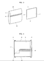
FIG. 3 is a perspective view showing a membrane element in the embodiment of the present invention; -
FIG. 4 is a front view showing the membrane element; -
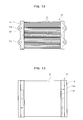
FIG. 5 is a plan view of the membrane module in the embodiment; -
FIG. 6 is a front view of the membrane module in the embodiment; -
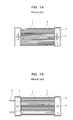
FIG. 7 is a plan view of a membrane module in another embodiment of the present invention; -
FIG. 8 is a side view of the membrane module in the other embodiment of the present invention; -
FIG. 9 is a plan view of a membrane module in another embodiment of the present invention; -
FIG. 10 is a plan view of a membrane module in another embodiment of the present invention; -
FIG. 11 is a front view of the membrane module in the other embodiment of the present invention; -
FIG. 12 is a plan view of a membrane module in another embodiment of the present invention; -
FIG. 13 is a front view of the membrane module in the other embodiment of the present invention; -
FIG. 14 is a plan view of a water collecting case in another embodiment of the present invention; -
FIG. 15 is a plan view of a water collecting case in another embodiment of the present invention; -
FIG. 16 is a plan view of a water collecting case in another embodiment of the present invention; -
FIG. 17 is a plan view of a water collecting case in another embodiment of the present invention; -
FIG. 18 is a plan view showing a conventional membrane module; and -
FIG. 19 is a plan view showing the conventional membrane module. - Embodiments of the present invention are explained below with reference to the accompanying drawings. In
FIGS. 1 to 6 , amembrane cassette 11 of a membrane separator includes a plurality of vertically-stackedmembrane modules 12. Themembrane cassette 11 is immersed and set in a liquid to be treated in a treatment tank (not shown). In themembrane cassette 11, anair diffuser 11a is arranged below thelower membrane module 12. The membrane separator can be formed of a single membrane module. - In the
membrane module 12, a plurality ofmembrane elements 13 are arranged in parallel at predetermined intervals. Channels for a liquid to be treated are formed in a vertical direction between themembrane elements 13. Both sides of themembrane elements 13 along the flow of the liquid to be treated are water-tightly sealed towater collecting cases 14. Each of thewater collecting cases 14 is hollow-shaped and has a water collecting space therein. However, thewater collecting case 14 can be provided only on one side of themembrane element 13. In this case, the other side of themembrane element 13 is sealed by resin or the like explained later. - In this embodiment, a configuration in which the
membrane elements 13 are arranged in the up-to-down direction is explained. However, the arrangement direction of themembrane elements 13 is not limited to the up-to-down direction. Themembrane elements 13 only have to be arranged along the flowing direction of the liquid to be treated. It is also possible to arrange themembrane elements 13 in the horizontal direction or obliquely. - The
membrane module 12 includesupper coupling portions 23 provided on the upper end faces of thewater collecting cases 14 andlower coupling portions 24 provided on the lower end faces thereof. Theupper coupling portions 23 and thelower coupling portions 24 form water collecting ports and communicate withwater collecting spaces 14a of thewater collecting cases 14. - The
lower coupling portions 24 of theupper membrane module 12 and theupper coupling portions 23 of thelower membrane module 12 are coupled to each other. Theupper coupling portions 23 of thewater collecting cases 14 in theupper membrane module 12 communicate withwater collecting pipes 26 viatubes 25. - In this embodiment, the
lower coupling portions 24 of thelower membrane module 12 are closed by plugs (not shown). However, it is possible to use a membrane module having nolower coupling portions 24 as thelower membrane module 12. - Extraction of permeate only has to be performed from at least one portion of the left and right
upper coupling portions 23 in theupper membrane module 12 and the left and rightlower coupling portions 24 in thelower membrane module 12. - As shown in
FIG. 2 , in each of thewater collecting cases 14, the plurality ofmembrane elements 13 are held water-tight via a sealing material (resin, etc.) 16 potted in anopening portion 15. However, thewater collecting case 14 is not limited to the configuration shown inFIG. 2 . There are various structures for water-tightly joining themembrane elements 13 to thewater collecting case 14. For example, it is possible to form the openingportion 15 of thewater collecting case 14 as a plurality of slits instead of a single opening, insert themembrane elements 13 in the slits, and pot the sealingmaterial 16 of resin or the like in the slits. Alternatively, it is also possible to arrange a seal material such as rubber around themembrane elements 13. - As shown in
FIGS. 3 and 4 , themembrane element 13 includes afiltration plate 17 made of resin, which forms a membrane supporting member, and afiltration membrane 18 made of a flat membrane (an organic membrane) arranged to cover the surfaces on the front and back of thefiltration plate 17. In each of themembrane elements 13, a permeate channel formed between the surfaces on the front and back of thefiltration plate 17 and thefiltration membrane 18 communicates with thewater collecting space 14a of thewater collecting case 14. In this embodiment, thefiltration plate 17 made of resin is explained as an example of the membrane supporting member. However, in some case, a flexible material such as nonwoven fabric or a net is used for the membrane supporting member. - The upper end side of the
membrane element 13 is located on the downstream side in the flowing direction of the liquid to be treated. The lower end side of themembrane element 13 is located on the upstream side in the flowing direction of the liquid to be treated. Thefiltration membrane 18 includes a downstream side reversedportion 20 folded so as to include anend 19 on the downstream side of thefiltration plate 17 and an upstream side reversedportion 29 folded so as to include anend 27 on the upstream side thereof. The ends of thefiltration membrane 18 overlap each other on the surfaces or end faces of thefiltration plate 17. One end located on the outer side of thefiltration membrane 18 extends toward the downstream side and joins the ends of thefiltration membrane 18 to form a joinedportion 30. The joinedportion 30 is formed by welding with ultrasound or bonding with an adhesive. - The
membrane elements 13 having this structure are arranged in parallel at predetermined intervals. The plurality ofmembrane elements 13 are bound on thefiltration plate 17 by the sealing material (resin, etc.) 16 arranged between themembrane elements 13 and are water-tightly sealed in the openingportion 15 of thewater collecting case 14 by the sealingmaterial 16. The sealingmaterial 16 has only to ensure water-tightness with thefiltration membrane 18. It is not always necessary to strongly press thefiltration membrane 18 against thefiltration plate 17. - With this configuration, the
membrane element 13 has a structure in which thefiltration plate 17 and thefiltration membrane 18 are not directly fixed and joined. A structure in which thefiltration membrane 18 and thefiltration plate 17 are not directly fixed on four sides of thefiltration plate 17 by bonding or welding is realised. However, in themembrane element 13, thefiltration plate 17 and thefiltration membrane 18 can be directly joined in an area where the membrane surface of thefiltration membrane 18 does not come into contact with the liquid to be treated, for example, an area corresponding to the sealingmaterial 16 or an area located inside thewater collecting case 14. This is on the condition that the joining does not hinder the permeate channel. - As shown in
FIG. 4 , the sealingmaterial 16 can be formed for each of themembrane element 13. The edge side portion of thefiltration membrane 18 is bound by the sealing material on thefiltration plate 17 for each of themembrane elements 13 on both sides of thefiltration plate 17 along the flowing direction of the liquid to be treated. - Thereafter, it is possible to arrange the
membrane elements 13 having this structure in parallel at predetermined intervals and bind the plurality ofmembrane elements 13 with the sealing material (resin, etc.) 16 arranged between themembrane elements 13. Further, as explained above, it is possible to arrange a seal material such as a rubber material on thefiltration membrane 18 and join thefiltration membrane 18 to thefiltration plate 17. - In the embodiment, the loop-shaped
filtration membrane 18 is formed by one membrane sheet. However, it is possible to form the loop-shapedfiltration membrane 18 with a plurality of membrane sheets. Further, thefiltration membrane 18 can be formed of a loop-shaped seamless membrane sheet. - In this embodiment, the membrane sheet is loop-shaped. However, the
filtration membrane 18 can be joined to thefiltration plate 17 at one of the upstream side end and the downstream side end of themembrane element 13 or both. This is on the condition that the inside of themembrane element 13 is not over-pressurized during chemical cleaning. - As shown in
FIG. 5 , in thewater collecting case 14, out ofwall members 41 arranged to surround thewater collecting space 14a, at least thewall member 41 opposed to the sides of themembrane elements 13 forms a projectingportion 41a projecting to the outer side and recessedportions 41b recessed to the inner side on both sides of the projectingportion 41a. The projectingportion 41a and the recessedportions 41b are desirably formed to have curved surfaces and form a continuous curved surface. - In this way, since the
wall member 41 forms the projectingportion 41a projecting to the outer side and the recessedportions 41b recessed to the inner side, the buckling load of thewall member 41 increases. Therefore, when thewater collecting space 14a in this embodiment is formed to have the same capacity as that of the water collecting case in the conventional configuration, for example, as shown inFIG. 5 , even when the sectional area and a width W of thewater collecting space 14a are set the same as the sectional area and width of the conventional water collecting space, a water collecting case with improved strength can be realized. Thewater collecting case 14 is unlikely to be broken even if themembrane modules 12 are stacked in multiple stages. - The
wall member 41 forms the projectingportion 41a projecting to the outer side to form an expanded area 14b in thewater collecting space 14a. Theupper coupling portion 23 and thelower coupling portion 24 forming the water collecting port are opened so as to face the expanded area 14b. - With this configuration, a channel around the
upper coupling portion 23 and thelower coupling portion 24 forming the water collecting port is widened. Therefore, even if permeate flowing in from therespective membrane elements 13 meets together and flows toward the upper coupling portion 23 (the lower coupling portion 24), it is possible to suppress an increase in channel resistance near the upper coupling portion 23 (the lower coupling portion 24) and contribute to the equalization of flow rate of the permeate flowing through therespective membrane elements 13. - In this embodiment, the
water collecting case 14 includes only thewall members 41. However, as shown inFIGS. 7 and 8 , it is possible to provideribs 42 on the outer side of thewall members 41 surrounding thewater collecting space 14a. In theribs 42,longitudinal ribs 42a andlateral ribs 42b are arranged lengthwise and crosswise. Theribs 42 are shaped so as to fit within the overall length dimension of the membrane separator along a direction in which the water collecting cases are arranged. - with this configuration, the
ribs 42 do not constitute a factor that prevents the flow of the liquid to be treated, the external dimension of the membrane separator is not increased, and it is possible to increase the strength of thewater collecting case 14. - In the
membrane module 12 according to the present invention, the following operations and effects are achieved. - Air is diffused as a gas for aeration from the
air diffuser 11a arranged below thelower membrane module 12. Upflow of air-liquid mixtures is caused inside themembrane cassette 11 by the air-lift action of bubbles of the air. The liquid to be treated in a treatment tank (not shown) is supplied between themembrane elements 13 by this upflow. A flow of the liquid to be treated along the membrane surfaces of themembrane elements 13 is formed. The liquid to be treated is supplied as a cross flow with respect to the flow of the permeate flowing to permeate through thefiltration membranes 18. - In this embodiment, the liquid to be treated is supplied as the cross flow by the upflow caused by the air-lift action. Therefore, the
membrane elements 13 are arranged in the up-to-down direction. However, when the liquid to be treated is supplied as the cross flow between themembrane elements 13 by a power unit such as a pump, themembrane elements 13 can also be arranged in the horizontal or oblique direction. - There are various systems for applying a driving pressure to the
membrane elements 13. In this embodiment, an activated sludge mixture in the tank is gravity-filtrated by themembrane elements 13 with a water head in the tank as a driving pressure. Alternatively, a suction pressure is applied to themembrane module 12 of themembrane cassette 11 as a driving pressure through thewater collecting pipes 26 and thetubes 25 by a suction pump to suck and filter the activated sludge mixture. - The permeate having received the driving pressure and permeated through the
filtration membranes 18 of themembrane elements 13 flows into thewater collecting spaces 14a of thewater collecting cases 14 through the permeate channels between thefiltration membranes 18 and thefiltration plates 17. - At this point, even if the permeate flowing in from the
respective membrane elements 13 meets together and flows toward theupper coupling portions 23 and thelower coupling portions 24, it is possible to suppress an increase in channel resistance near the upper coupling portions 23 (the lower coupling portions 24) and contribute to the equalization of flow rate of the permeate flowing through therespective membrane elements 13. - The permeate having flowed into the
water collecting cases 14 of themembrane module 12 flows into thewater collecting cases 14 of theupper membrane module 12 from thelower coupling portions 24 through theupper coupling portions 23. The permeate having flowed into thewater collecting cases 14 of theupper membrane module 12 is led out to the outside of the tank as treated water from theupper coupling portions 23 through thetubes 25 and thewater collecting pipes 26. - During this operation, the activated sludge mixture is supplied as a cross flow to the channels among the
membrane elements 13 by upflow. The membrane surfaces of themembrane elements 13 are aerated and cleaned by the upflow. Thus a decrease in separating function due to fouling is suppressed and the membrane separator is prevented from being nonfunctional. - In the case of the gravity filtration, valves (not shown) provided in the
water collecting pipes 26 are closed. In the case of the suction filtration, the suction pump is stopped to stop the filtration operation. When theair diffuser 11a is operated to perform the aeration and cleaning in this state, an excellent cleaning effect can be obtained. - At this point, the upflow pushes the permeate in each of the
membrane elements 13 to the upper downstream side between thefiltration plate 17 and thefiltration membrane 18. - The
filtration membrane 18 includes the reversedportion 20 folded to include theend 19 on the downstream side of thefiltration plate 17. Therefore, the permeate pushed to the upper downstream side between thefiltration plate 17 and thefiltration membrane 18 is collected in the reversedportion 20. Thefiltration membrane 18 flexibly swells in the reversedportion 20 to allow the permeate to move. - Further, since the swell of the reversed
portion 20 is formed in the downstream area of theend 19 on the downstream side of thefiltration plate 17, the swell of the reversedportion 20 does not act as a resistance against the upflow flowing along thefiltration plate 17. Vibrations and stresses do not occur in thefiltration membrane 18 because of the swell of the reversedportion 20. - Therefore, a load acting on the
filtration membrane 18 is suppressed to prevent thefiltration membrane 18 from being broken because the reversedportion 20 flexibly swells to allow the permeate to move and the swell does not act as a resistance against the upflow. Chemical cleaning
During chemical cleaning, a chemical is supplied to each of themembrane modules 12 of themembrane cassette 11 through thewater collecting pipes 26 and thetubes 25. The chemical is supplied at a predetermined pressure to the permeate between thefiltration plate 17 and thefiltration membrane 18. At this point, thefiltration membrane 18 receives an internal pressure and swells to the outer side. In this state, a tensile stress acts on thefiltration membrane 18 along the membrane surface. - However, when the ends of the
filtration membrane 18 are joined in the joinedportion 30 to form the loop-shapedfiltration membrane 18, there is no region where thefiltration membrane 18 and thefiltration plate 17 are directly fixed. Therefore, for example, compared with the case in which the membrane supporting member and the filtration membrane are welded, it is possible to suppress breakage of thefiltration membrane 18 and apply a high internal pressure in chemical cleaning. - In this embodiment, the ends of both membrane sheets are stacked on top of each other on the surfaces of the
filtration plate 17 and the ends of both membrane sheets are joined to form the joinedportion 30. Therefore, since a tensile stress acting on thefiltration membrane 18 acts as a shearing force in the joinedportion 30, a large joining strength can be secured. Further, on both sides along the flowing direction of the liquid to be treated of themembrane element 13, the sealingmaterial 16 binds thefiltration membrane 18 on thefiltration plate 17 from the outer side. Therefore, even if thefiltration membrane 18 receives an internal pressure and swells to the outer side, a large strength can be secured. - Therefore, it is possible to perform, while suppressing breakage of the
filtration membrane 18 in chemical cleaning, reverse liquid cleaning for feeding a chemical in a short time under a high pressure and causing the chemical to permeate from the inner side to the outer side under a high internal pressure. - In the
water collecting case 14, thewall member 41 continuously forms the projectingportion 41a and therecesses 41b that form curved surfaces. Therefore, the buckling load of thewall member 41 increases, the anti-pressure strength against the internal and external pressures increases, and thewater collecting case 14 is not broken even under the supply pressure of the chemical and the driving pressure during the filtration operation. Further, since theribs 42 are provided, the anti-pressure strength increases. - As shown in
FIG. 9 , in thewater collecting case 14, the projectingportion 41a formed in thewall member 41 may be formed in a plurality of places. The recessedportions 41b are formed on both sides of the projectingportions 41a. However, the recessedportions 41b can be formed only between the projectingportions 41a. - As shown in
FIGS. 10 and 11 , thelongitudinal ribs 42a and thelateral ribs 42b of theribs 42 provided on the outer side of thewall member 41 can be formed shorter than the overall length dimension of the membrane separator along the inter-water collecting case direction. In this case, as shown inFIGS. 12 and 13 , the projectingportion 41a formed in thewall member 41 may be formed in a plurality of places. The recessedportions 41b are formed on both sides of the projectingportions 41a. - As shown in
FIG. 14 , in thewater collecting case 14, the projectingportion 41a formed in thewall member 41 can be formed in a rectangular shape in section. The projecting corners of the projectingportion 41a and the recessed corners of the recessedportions 41b are not limited to right-angled corners and can be formed in a chamfered shape or a curved surface shape. - In this case, as shown in
FIG. 15 , thelongitudinal ribs 42a and thelateral ribs 42b of theribs 42 can be formed on the outer side of thewall member 41. - As shown in
FIG. 16 , in thewater collecting case 14, the projectingportion 41a formed in thewall member 41 can be formed in a triangular shape in section. The projecting corners of the projectingportion 41a and the recessed corners of the recessedportions 41b are not limited to right-angled corners and can be formed in a chamfered shape or a curved surface shape. - In this case, as shown in
FIG. 17 , thelongitudinal ribs 42a and thelateral ribs 42b of theribs 42 can be formed on the outer side of thewall member 41 and theribs 42 can be obliquely formed.
Claims (5)
- A membrane separator comprising:a plurality of membrane elements arranged in parallel to form channels for a liquid to be treated between the membrane elements; anda water collecting case which keeps water-tight sides of the membrane elements along the channels for the liquid to be treated, and has therein a water collecting space with which permeate channels of the membrane elements communicate, whereinin the water collecting case, out of wall members arranged to surround the water collecting space, at least the wall member opposed to the sides of the membrane elements forms a projecting portion projecting to an outer side and recessed portions recessed to an inner side.
- The membrane separator according to claim 1, wherein, in the water collecting case, the wall member opposed to the sides of the membrane elements forms the projecting portion projecting to the outer side, forms an expanded area in the water collecting space, and has a water collecting port opened so as to face the expanded area.
- The membrane separator according to claim 1 or 2, wherein the water collecting case has ribs on the outer sides of the wall members surrounding the water collecting space, and the ribs are shaped so as to fit within an overall length dimension of the membrane separator along a direction in which the water collecting cases are arranged.
- A membrane cassette using the membrane separator according to any one of claims 1 to 3, wherein a plurality of the membrane separators are vertically stacked in multiple stages along a flowing direction of a liquid to be treated.
- The membrane cassette according to claim 4, wherein the upper and lower membrane separators communicate with each other via water collecting ports that constitute coupling portions formed on wall surfaces opposed to each other of water collecting cases of the membrane separators.
Priority Applications (1)
| Application Number | Priority Date | Filing Date | Title |
|---|---|---|---|
| HRP20161700TT HRP20161700T1 (en) | 2008-03-27 | 2008-03-27 | Membrane separator and membrane cassette |
Applications Claiming Priority (1)
| Application Number | Priority Date | Filing Date | Title |
|---|---|---|---|
| PCT/JP2008/000755 WO2009118787A1 (en) | 2008-03-27 | 2008-03-27 | Membrane separation apparatus and membrane cassette |
Publications (3)
| Publication Number | Publication Date |
|---|---|
| EP2260928A1 true EP2260928A1 (en) | 2010-12-15 |
| EP2260928A4 EP2260928A4 (en) | 2013-11-27 |
| EP2260928B1 EP2260928B1 (en) | 2016-09-21 |
Family
ID=41113031
Family Applications (1)
| Application Number | Title | Priority Date | Filing Date |
|---|---|---|---|
| EP08720634.8A Active EP2260928B1 (en) | 2008-03-27 | 2008-03-27 | Membrane separator and membrane cassette |
Country Status (6)
| Country | Link |
|---|---|
| US (1) | US8741141B2 (en) |
| EP (1) | EP2260928B1 (en) |
| JP (1) | JP5283689B2 (en) |
| CN (1) | CN101980765B (en) |
| HR (1) | HRP20161700T1 (en) |
| WO (1) | WO2009118787A1 (en) |
Cited By (1)
| Publication number | Priority date | Publication date | Assignee | Title |
|---|---|---|---|---|
| WO2016112121A1 (en) * | 2015-01-06 | 2016-07-14 | Nanostone Water Inc. | Fixture device for membrane assembly and related methods |
Families Citing this family (10)
| Publication number | Priority date | Publication date | Assignee | Title |
|---|---|---|---|---|
| WO2011100320A2 (en) * | 2010-02-09 | 2011-08-18 | Aquatech International Corporation | Advanced filtration device for water and wastewater treatment |
| JP5999696B2 (en) * | 2012-09-13 | 2016-09-28 | 株式会社日立製作所 | Membrane element, membrane module and membrane separation system |
| EP2767831A1 (en) * | 2013-02-19 | 2014-08-20 | DST Diagnostische Systeme & Technologien GmbH | New PoC test system and method |
| AU2015337112A1 (en) | 2014-10-22 | 2017-05-18 | Koch Membrane Systems, Inc. | Membrane module system with bundle enclosures and pulsed aeration and method of operation |
| USD764019S1 (en) * | 2015-02-20 | 2016-08-16 | Kubota Corporation | Filter |
| USD779631S1 (en) | 2015-08-10 | 2017-02-21 | Koch Membrane Systems, Inc. | Gasification device |
| CN109311703B (en) * | 2016-05-31 | 2020-02-11 | 株式会社明电舍 | Membrane separation device, structure for arranging membrane elements, and membrane cartridge and membrane unit |
| JP7035398B2 (en) * | 2017-09-14 | 2022-03-15 | 株式会社明電舎 | Water collection structure |
| CA3073341A1 (en) | 2017-10-10 | 2019-04-18 | Tangent Company Llc | Filtration unit |
| CN114100371B (en) * | 2021-12-10 | 2024-04-09 | 雅安沃克林环保科技有限公司 | Dull and stereotyped membrane module of pottery and membrane heap |
Family Cites Families (16)
| Publication number | Priority date | Publication date | Assignee | Title |
|---|---|---|---|---|
| JPS5394941U (en) * | 1976-12-29 | 1978-08-02 | ||
| JPS5394941A (en) | 1977-01-28 | 1978-08-19 | Ricoh Co Ltd | Magnetic brush developing device |
| JP3250274B2 (en) | 1992-10-08 | 2002-01-28 | 東レ株式会社 | Filter |
| JP2927157B2 (en) * | 1993-09-24 | 1999-07-28 | 株式会社ユアサコーポレーション | Suction filtration module |
| US7037426B2 (en) * | 2000-05-04 | 2006-05-02 | Zenon Environmental Inc. | Immersed membrane apparatus |
| JPH09276669A (en) * | 1996-04-17 | 1997-10-28 | Mitsubishi Rayon Co Ltd | Hollow fiber membrane module unit and filtration device |
| WO1998007506A1 (en) * | 1996-08-22 | 1998-02-26 | Mitsubishi Rayon Co., Ltd. | Hollow fiber membrane module, hollow fiber membrane module unit using the same, and septic tank provided with the module unit |
| US6280626B1 (en) | 1998-08-12 | 2001-08-28 | Mitsubishi Rayon Co., Ltd. | Membrane separator assembly and method of cleaning the assembly utilizing gas diffuser underneath the assembly |
| JP3815645B2 (en) * | 1999-02-16 | 2006-08-30 | 株式会社日立プラントテクノロジー | Immersion type flat membrane separator and control method thereof |
| JP3929194B2 (en) | 1999-02-17 | 2007-06-13 | 株式会社荏原製作所 | Hollow fiber membrane unit and membrane separator |
| US7387730B2 (en) | 2000-12-18 | 2008-06-17 | Mitsubishi Rayon Co., Ltd. | Hollow fiber membrane module, method of manufacturing the hollow fiber membrane module, and housing for hollow fiber membrane module |
| JP4755351B2 (en) | 2001-03-14 | 2011-08-24 | 三菱レイヨン株式会社 | Membrane module housing, membrane module using the same, and manufacturing method thereof |
| JP2002248323A (en) * | 2001-02-23 | 2002-09-03 | Katsumi Sugimoto | Filtration device |
| KR100661935B1 (en) | 2002-09-27 | 2006-12-28 | 미쯔비시 레이온 가부시끼가이샤 | Hollow fiber membrane module, hollow fiber membrane module unit, membrane filtering device using the module unit, and method of operating the membrane filtering device |
| US7294259B2 (en) * | 2003-02-13 | 2007-11-13 | Zenon Technology Partnership | Membrane module for gas transfer |
| JP5394941B2 (en) | 2010-01-04 | 2014-01-22 | 新神戸電機株式会社 | ELECTRODE GROUP FOR LITHIUM ION CAPACITOR, ITS MANUFACTURING METHOD, AND LITHIUM ION CAPACITOR |
-
2008
- 2008-03-27 JP JP2010505031A patent/JP5283689B2/en active Active
- 2008-03-27 HR HRP20161700TT patent/HRP20161700T1/en unknown
- 2008-03-27 CN CN200880128341.XA patent/CN101980765B/en active Active
- 2008-03-27 US US12/736,236 patent/US8741141B2/en active Active
- 2008-03-27 WO PCT/JP2008/000755 patent/WO2009118787A1/en not_active Ceased
- 2008-03-27 EP EP08720634.8A patent/EP2260928B1/en active Active
Cited By (2)
| Publication number | Priority date | Publication date | Assignee | Title |
|---|---|---|---|---|
| WO2016112121A1 (en) * | 2015-01-06 | 2016-07-14 | Nanostone Water Inc. | Fixture device for membrane assembly and related methods |
| CN107206326A (en) * | 2015-01-06 | 2017-09-26 | 纳诺斯通水务公司 | Fixtures and related methods for membrane modules |
Also Published As
| Publication number | Publication date |
|---|---|
| JPWO2009118787A1 (en) | 2011-07-21 |
| WO2009118787A1 (en) | 2009-10-01 |
| US8741141B2 (en) | 2014-06-03 |
| CN101980765A (en) | 2011-02-23 |
| HRP20161700T1 (en) | 2017-02-10 |
| JP5283689B2 (en) | 2013-09-04 |
| CN101980765B (en) | 2015-11-25 |
| EP2260928A4 (en) | 2013-11-27 |
| US20110005993A1 (en) | 2011-01-13 |
| EP2260928B1 (en) | 2016-09-21 |
Similar Documents
| Publication | Publication Date | Title |
|---|---|---|
| US8741141B2 (en) | Membrane separator and membrane cassette | |
| EP2260929A1 (en) | Membrane element and membrane module | |
| US20110011787A1 (en) | Membrane element and membrane module | |
| CN102481522B (en) | Filtration module including membrane sheet with capillary channels | |
| CN104334259B (en) | Hollow fiber membrane module and hollow fiber membrane unit having hollow fiber membrane module | |
| WO2007122839A1 (en) | Membrane element, membrane unit and multistage membrane unit | |
| JP5566031B2 (en) | Spacing member, membrane element, and submerged membrane separator | |
| EP2666536B1 (en) | Membrane separation device | |
| KR20150036221A (en) | Element unit, separation membrane module, and method for connecting/disconnecting separation membrane element | |
| CN101405073A (en) | Membrane element, membrane unit and multistage membrane unit | |
| EP2236196A2 (en) | Membrane cartridge in immersion type membrane separation apparatus | |
| CN102292145B (en) | Membrane separation device | |
| JP2007268388A (en) | Membrane cartridge and submerged membrane separator | |
| JP2008246356A (en) | Membrane cartridge | |
| CN206778195U (en) | Membrane module and film filter for water process | |
| JP5105787B2 (en) | Membrane cartridge | |
| JP5442073B2 (en) | Membrane cartridge | |
| CN206793420U (en) | Membrane module and film filter for water process | |
| JP7749978B2 (en) | Hollow fiber membrane element, hollow fiber membrane module, water treatment device, and water treatment method | |
| CN106237860A (en) | The membrane module processed for water and film filter | |
| JPS6233503A (en) | Membrane set for fluid separator | |
| CN106310952A (en) | Membrane module for water treatment and membrane filter |
Legal Events
| Date | Code | Title | Description |
|---|---|---|---|
| PUAI | Public reference made under article 153(3) epc to a published international application that has entered the european phase |
Free format text: ORIGINAL CODE: 0009012 |
|
| 17P | Request for examination filed |
Effective date: 20101027 |
|
| AK | Designated contracting states |
Kind code of ref document: A1 Designated state(s): AT BE BG CH CY CZ DE DK EE ES FI FR GB GR HR HU IE IS IT LI LT LU LV MC MT NL NO PL PT RO SE SI SK TR |
|
| AX | Request for extension of the european patent |
Extension state: AL BA MK RS |
|
| DAX | Request for extension of the european patent (deleted) | ||
| A4 | Supplementary search report drawn up and despatched |
Effective date: 20131025 |
|
| RIC1 | Information provided on ipc code assigned before grant |
Ipc: B01D 69/06 20060101ALI20131021BHEP Ipc: B01D 61/20 20060101ALI20131021BHEP Ipc: B01D 63/08 20060101AFI20131021BHEP Ipc: B01D 61/18 20060101ALI20131021BHEP Ipc: B01D 65/00 20060101ALI20131021BHEP Ipc: C02F 1/44 20060101ALI20131021BHEP Ipc: B01D 69/10 20060101ALI20131021BHEP |
|
| 17Q | First examination report despatched |
Effective date: 20140703 |
|
| GRAP | Despatch of communication of intention to grant a patent |
Free format text: ORIGINAL CODE: EPIDOSNIGR1 |
|
| INTG | Intention to grant announced |
Effective date: 20160511 |
|
| GRAS | Grant fee paid |
Free format text: ORIGINAL CODE: EPIDOSNIGR3 |
|
| GRAA | (expected) grant |
Free format text: ORIGINAL CODE: 0009210 |
|
| AK | Designated contracting states |
Kind code of ref document: B1 Designated state(s): AT BE BG CH CY CZ DE DK EE ES FI FR GB GR HR HU IE IS IT LI LT LU LV MC MT NL NO PL PT RO SE SI SK TR |
|
| REG | Reference to a national code |
Ref country code: GB Ref legal event code: FG4D |
|
| REG | Reference to a national code |
Ref country code: CH Ref legal event code: EP |
|
| REG | Reference to a national code |
Ref country code: AT Ref legal event code: REF Ref document number: 830594 Country of ref document: AT Kind code of ref document: T Effective date: 20161015 |
|
| REG | Reference to a national code |
Ref country code: IE Ref legal event code: FG4D |
|
| REG | Reference to a national code |
Ref country code: DE Ref legal event code: R096 Ref document number: 602008046384 Country of ref document: DE |
|
| REG | Reference to a national code |
Ref country code: HR Ref legal event code: TUEP Ref document number: P20161700 Country of ref document: HR |
|
| REG | Reference to a national code |
Ref country code: LT Ref legal event code: MG4D Ref country code: NL Ref legal event code: MP Effective date: 20160921 |
|
| PG25 | Lapsed in a contracting state [announced via postgrant information from national office to epo] |
Ref country code: NO Free format text: LAPSE BECAUSE OF FAILURE TO SUBMIT A TRANSLATION OF THE DESCRIPTION OR TO PAY THE FEE WITHIN THE PRESCRIBED TIME-LIMIT Effective date: 20161221 Ref country code: LT Free format text: LAPSE BECAUSE OF FAILURE TO SUBMIT A TRANSLATION OF THE DESCRIPTION OR TO PAY THE FEE WITHIN THE PRESCRIBED TIME-LIMIT Effective date: 20160921 Ref country code: FI Free format text: LAPSE BECAUSE OF FAILURE TO SUBMIT A TRANSLATION OF THE DESCRIPTION OR TO PAY THE FEE WITHIN THE PRESCRIBED TIME-LIMIT Effective date: 20160921 |
|
| REG | Reference to a national code |
Ref country code: HR Ref legal event code: T1PR Ref document number: P20161700 Country of ref document: HR |
|
| REG | Reference to a national code |
Ref country code: AT Ref legal event code: MK05 Ref document number: 830594 Country of ref document: AT Kind code of ref document: T Effective date: 20160921 |
|
| PG25 | Lapsed in a contracting state [announced via postgrant information from national office to epo] |
Ref country code: GR Free format text: LAPSE BECAUSE OF FAILURE TO SUBMIT A TRANSLATION OF THE DESCRIPTION OR TO PAY THE FEE WITHIN THE PRESCRIBED TIME-LIMIT Effective date: 20161222 Ref country code: SE Free format text: LAPSE BECAUSE OF FAILURE TO SUBMIT A TRANSLATION OF THE DESCRIPTION OR TO PAY THE FEE WITHIN THE PRESCRIBED TIME-LIMIT Effective date: 20160921 Ref country code: NL Free format text: LAPSE BECAUSE OF FAILURE TO SUBMIT A TRANSLATION OF THE DESCRIPTION OR TO PAY THE FEE WITHIN THE PRESCRIBED TIME-LIMIT Effective date: 20160921 Ref country code: LV Free format text: LAPSE BECAUSE OF FAILURE TO SUBMIT A TRANSLATION OF THE DESCRIPTION OR TO PAY THE FEE WITHIN THE PRESCRIBED TIME-LIMIT Effective date: 20160921 |
|
| REG | Reference to a national code |
Ref country code: FR Ref legal event code: PLFP Year of fee payment: 10 |
|
| PG25 | Lapsed in a contracting state [announced via postgrant information from national office to epo] |
Ref country code: EE Free format text: LAPSE BECAUSE OF FAILURE TO SUBMIT A TRANSLATION OF THE DESCRIPTION OR TO PAY THE FEE WITHIN THE PRESCRIBED TIME-LIMIT Effective date: 20160921 Ref country code: RO Free format text: LAPSE BECAUSE OF FAILURE TO SUBMIT A TRANSLATION OF THE DESCRIPTION OR TO PAY THE FEE WITHIN THE PRESCRIBED TIME-LIMIT Effective date: 20160921 |
|
| PG25 | Lapsed in a contracting state [announced via postgrant information from national office to epo] |
Ref country code: AT Free format text: LAPSE BECAUSE OF FAILURE TO SUBMIT A TRANSLATION OF THE DESCRIPTION OR TO PAY THE FEE WITHIN THE PRESCRIBED TIME-LIMIT Effective date: 20160921 Ref country code: IS Free format text: LAPSE BECAUSE OF FAILURE TO SUBMIT A TRANSLATION OF THE DESCRIPTION OR TO PAY THE FEE WITHIN THE PRESCRIBED TIME-LIMIT Effective date: 20170121 Ref country code: BG Free format text: LAPSE BECAUSE OF FAILURE TO SUBMIT A TRANSLATION OF THE DESCRIPTION OR TO PAY THE FEE WITHIN THE PRESCRIBED TIME-LIMIT Effective date: 20161221 Ref country code: PL Free format text: LAPSE BECAUSE OF FAILURE TO SUBMIT A TRANSLATION OF THE DESCRIPTION OR TO PAY THE FEE WITHIN THE PRESCRIBED TIME-LIMIT Effective date: 20160921 Ref country code: CZ Free format text: LAPSE BECAUSE OF FAILURE TO SUBMIT A TRANSLATION OF THE DESCRIPTION OR TO PAY THE FEE WITHIN THE PRESCRIBED TIME-LIMIT Effective date: 20160921 Ref country code: SK Free format text: LAPSE BECAUSE OF FAILURE TO SUBMIT A TRANSLATION OF THE DESCRIPTION OR TO PAY THE FEE WITHIN THE PRESCRIBED TIME-LIMIT Effective date: 20160921 Ref country code: PT Free format text: LAPSE BECAUSE OF FAILURE TO SUBMIT A TRANSLATION OF THE DESCRIPTION OR TO PAY THE FEE WITHIN THE PRESCRIBED TIME-LIMIT Effective date: 20170123 Ref country code: ES Free format text: LAPSE BECAUSE OF FAILURE TO SUBMIT A TRANSLATION OF THE DESCRIPTION OR TO PAY THE FEE WITHIN THE PRESCRIBED TIME-LIMIT Effective date: 20160921 |
|
| REG | Reference to a national code |
Ref country code: DE Ref legal event code: R097 Ref document number: 602008046384 Country of ref document: DE |
|
| PLBE | No opposition filed within time limit |
Free format text: ORIGINAL CODE: 0009261 |
|
| STAA | Information on the status of an ep patent application or granted ep patent |
Free format text: STATUS: NO OPPOSITION FILED WITHIN TIME LIMIT |
|
| PG25 | Lapsed in a contracting state [announced via postgrant information from national office to epo] |
Ref country code: DK Free format text: LAPSE BECAUSE OF FAILURE TO SUBMIT A TRANSLATION OF THE DESCRIPTION OR TO PAY THE FEE WITHIN THE PRESCRIBED TIME-LIMIT Effective date: 20160921 |
|
| 26N | No opposition filed |
Effective date: 20170622 |
|
| REG | Reference to a national code |
Ref country code: DE Ref legal event code: R119 Ref document number: 602008046384 Country of ref document: DE |
|
| REG | Reference to a national code |
Ref country code: CH Ref legal event code: PL |
|
| PG25 | Lapsed in a contracting state [announced via postgrant information from national office to epo] |
Ref country code: SI Free format text: LAPSE BECAUSE OF FAILURE TO SUBMIT A TRANSLATION OF THE DESCRIPTION OR TO PAY THE FEE WITHIN THE PRESCRIBED TIME-LIMIT Effective date: 20160921 Ref country code: MC Free format text: LAPSE BECAUSE OF FAILURE TO SUBMIT A TRANSLATION OF THE DESCRIPTION OR TO PAY THE FEE WITHIN THE PRESCRIBED TIME-LIMIT Effective date: 20160921 |
|
| REG | Reference to a national code |
Ref country code: IE Ref legal event code: MM4A |
|
| PG25 | Lapsed in a contracting state [announced via postgrant information from national office to epo] |
Ref country code: LU Free format text: LAPSE BECAUSE OF NON-PAYMENT OF DUE FEES Effective date: 20170327 Ref country code: DE Free format text: LAPSE BECAUSE OF NON-PAYMENT OF DUE FEES Effective date: 20171003 |
|
| REG | Reference to a national code |
Ref country code: FR Ref legal event code: PLFP Year of fee payment: 11 |
|
| PG25 | Lapsed in a contracting state [announced via postgrant information from national office to epo] |
Ref country code: LI Free format text: LAPSE BECAUSE OF NON-PAYMENT OF DUE FEES Effective date: 20170331 Ref country code: CH Free format text: LAPSE BECAUSE OF NON-PAYMENT OF DUE FEES Effective date: 20170331 Ref country code: IE Free format text: LAPSE BECAUSE OF NON-PAYMENT OF DUE FEES Effective date: 20170327 |
|
| PG25 | Lapsed in a contracting state [announced via postgrant information from national office to epo] |
Ref country code: MT Free format text: LAPSE BECAUSE OF NON-PAYMENT OF DUE FEES Effective date: 20170327 |
|
| REG | Reference to a national code |
Ref country code: HR Ref legal event code: ODRP Ref document number: P20161700 Country of ref document: HR Payment date: 20190218 Year of fee payment: 12 |
|
| PG25 | Lapsed in a contracting state [announced via postgrant information from national office to epo] |
Ref country code: HU Free format text: LAPSE BECAUSE OF FAILURE TO SUBMIT A TRANSLATION OF THE DESCRIPTION OR TO PAY THE FEE WITHIN THE PRESCRIBED TIME-LIMIT; INVALID AB INITIO Effective date: 20080327 |
|
| PG25 | Lapsed in a contracting state [announced via postgrant information from national office to epo] |
Ref country code: CY Free format text: LAPSE BECAUSE OF NON-PAYMENT OF DUE FEES Effective date: 20160921 |
|
| REG | Reference to a national code |
Ref country code: HR Ref legal event code: ODRP Ref document number: P20161700 Country of ref document: HR Payment date: 20200213 Year of fee payment: 13 |
|
| REG | Reference to a national code |
Ref country code: HR Ref legal event code: ODRP Ref document number: P20161700 Country of ref document: HR Payment date: 20210324 Year of fee payment: 14 |
|
| REG | Reference to a national code |
Ref country code: HR Ref legal event code: ODRP Ref document number: P20161700 Country of ref document: HR Payment date: 20220325 Year of fee payment: 15 |
|
| REG | Reference to a national code |
Ref country code: HR Ref legal event code: ODRP Ref document number: P20161700 Country of ref document: HR Payment date: 20230215 Year of fee payment: 16 |
|
| REG | Reference to a national code |
Ref country code: HR Ref legal event code: ODRP Ref document number: P20161700 Country of ref document: HR Payment date: 20240208 Year of fee payment: 17 |
|
| REG | Reference to a national code |
Ref country code: HR Ref legal event code: ODRP Ref document number: P20161700 Country of ref document: HR Payment date: 20250207 Year of fee payment: 18 |
|
| PGFP | Annual fee paid to national office [announced via postgrant information from national office to epo] |
Ref country code: GB Payment date: 20260209 Year of fee payment: 19 |
|
| REG | Reference to a national code |
Ref country code: HR Ref legal event code: ODRP Ref document number: P20161700 Country of ref document: HR Payment date: 20260205 Year of fee payment: 19 |
|
| PGFP | Annual fee paid to national office [announced via postgrant information from national office to epo] |
Ref country code: HR Payment date: 20260205 Year of fee payment: 19 |
|
| PGFP | Annual fee paid to national office [announced via postgrant information from national office to epo] |
Ref country code: BE Payment date: 20260217 Year of fee payment: 19 Ref country code: IT Payment date: 20260220 Year of fee payment: 19 |
|
| PGFP | Annual fee paid to national office [announced via postgrant information from national office to epo] |
Ref country code: FR Payment date: 20260209 Year of fee payment: 19 |
|
| PGFP | Annual fee paid to national office [announced via postgrant information from national office to epo] |
Ref country code: TR Payment date: 20260326 Year of fee payment: 19 |