EP2260693A1 - Knotter Arrangement - Google Patents
Knotter Arrangement Download PDFInfo
- Publication number
- EP2260693A1 EP2260693A1 EP10164720A EP10164720A EP2260693A1 EP 2260693 A1 EP2260693 A1 EP 2260693A1 EP 10164720 A EP10164720 A EP 10164720A EP 10164720 A EP10164720 A EP 10164720A EP 2260693 A1 EP2260693 A1 EP 2260693A1
- Authority
- EP
- European Patent Office
- Prior art keywords
- knotter
- frame
- lubricant
- spindle
- lubrication
- Prior art date
- Legal status (The legal status is an assumption and is not a legal conclusion. Google has not performed a legal analysis and makes no representation as to the accuracy of the status listed.)
- Granted
Links
Images


Classifications
-
- A—HUMAN NECESSITIES
- A01—AGRICULTURE; FORESTRY; ANIMAL HUSBANDRY; HUNTING; TRAPPING; FISHING
- A01F—PROCESSING OF HARVESTED PRODUCE; HAY OR STRAW PRESSES; DEVICES FOR STORING AGRICULTURAL OR HORTICULTURAL PRODUCE
- A01F15/00—Baling presses for straw, hay or the like
- A01F15/08—Details
- A01F15/14—Tying devices specially adapted for baling presses
- A01F15/145—Twine knotters
-
- A—HUMAN NECESSITIES
- A01—AGRICULTURE; FORESTRY; ANIMAL HUSBANDRY; HUNTING; TRAPPING; FISHING
- A01D—HARVESTING; MOWING
- A01D69/00—Driving mechanisms or parts thereof for harvesters or mowers
- A01D69/12—Lubrication
Definitions
- the present invention relates to a knotter arrangement having at least one knotter assembly with a knotter frame, said knotter frame having multiple lubrication points assigned to moveable knotter parts, and having a lubrication system with a least one fluid line supplying lubricant to the knotter assembly.
- a grease zerk or lubricating line is provided externally of the knotter frame for introducing lubricant to each of the joints defined between a given element and the knotter frame.
- a distributing valve to move lubrication to each of the joints through individual lubrication lines. This arrangement suffers from the disadvantage of requiring a multitude of lube lines some of which may become kinked as the knotter is rotated to a service position, and each lube line being associated with connections which may leak.
- an improved knotter arrangement with a knotter lubrication system which minimizes the number of lubrication lines, and hence, the number of connections which are subject to leakage.
- Said lubrication system employs the knotter frame as a lubrication manifold for distributing lubrication to the joints or lubrication points of various rotating knotter elements mounted to the knotter frame.
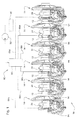
- a portion of a knotter arrangement 10 for a large square baler including a knotter drive shaft 12 supported at its opposite ends, in a manner not shown, for rotation about a horizontal transverse axis.
- Six identical knotter assemblies 14 are mounted at equally spaced locations along the shaft 12. It could be more or less than six assemblies.
- each knotter assembly 14 includes a drive gear 16 having an integral, leftwardly projecting cylindrical hub 18 received on, and keyed for rotation with, the drive shaft 12.
- the drive gear 16 further includes a pair of radially outer, annularly spaced gear tooth segments 20a and 20b, and a pair or radially inner, annularly spaced gear tooth segments 22a and 22b, respectively, having a purpose explained below.
- Each knotter assembly 14 further includes a knotter frame 24 having an upper end defined by a cylindrical sleeve 26 received about the knotter gear hub 18 so as to permit the hub 18 to rotate relative to the sleeve 26.
- a major portion of the frame 24 comprises a one-piece casting including an upper end defining a lower half 28a of the sleeve 26 and to which an upper half 28b of the sleeve is secured by a pair of bolts 30 projecting downwardly through holes provided in a first pair of lugs provided at opposite sides of the upper sleeve half 28b and being threaded into respective holes provided in a second pair of lugs provided at opposite sides of the lower sleeve half 28a.
- the sleeve 26 is captured between a shoulder provided on the gear 14 about the hub 18 and a snap ring 32 received in an annular ring groove provided in the hub 18.
- a middle frame section 38 containing a bore 40 Joined between the lower sleeve half 28a and right and left legs 34 and 36, respectively, of the frame 24 is a middle frame section 38 containing a bore 40 (see Figs. 4 and 5 ), which as viewed in Figs. 1 and 2 , is disposed along an upwardly and rearwardly inclined axis which extends perpendicular to the axis of the hub 18.
- a knife arm 42 is joined to a knife arm shaft 44 which projects rearwardly through, and is mounted for pivoting within the bore 40.
- the shaft 44 is held in place by a snap ring 46 received in an annular snap ring groove provided in a rear end region of the shaft 44.
- the knife arm 42 extends rightwardly beyond the shaft 44 and terminates at stub shaft carrying a roller 47 engaged with a cam surface 48 formed on the gear 16.
- the knotter frame 24 further includes a cylindrical ring 49 located between and joined to lower end regions of the legs 34 and 36, the ring 49 containing a bore 50 (see Fig. 4 ) having the same orientation as the bore 40.
- a twine disk 52 is fixed to a forward end region of a drive spindle 54 projecting rearwardly through, and being mounted for rotation within, the bore 50.
- a gear 56 is received on a rear end region of the spindle 54 and is retained there by a cross pin 58 received in aligned bores provided in the gear 56 and spindle 54.
- the right leg 34 includes a rearwardly offset region 60 which extends along the leg 34 from the middle section 38 to a location approximately at a level equal to that of a top of the ring 48.
- Extending lengthwise through the offset leg region 60 is an upright bore 61 ( Fig. 4 ) disposed along an axis extending perpendicular to the axis of the bore 50.
- a worm gear spindle 62 extends through, and is mounted for rotation within the bore 61 and has a gear 64 fixed to its upper end and located for meshing with the inner gear segments 22a and 22b, and has a worm gear 66 secured to its lower end by a nut 68 threaded onto a threaded lower end region of the spindle 62, with the worm gear 66 being meshed with the twine disk spindle gear 56.
- the middle section 38 of the frame 24 includes a forwardly projecting region 69 spaced vertically above a forwardly projecting region 70 of the leg 34.
- the regions 69 and 70 respectively contain axially aligned upper and lower sections 71 and 72 (see Fig. 5 ) of an upright bore in which is located a billhook spindle 74 having a drive gear 76 mounted thereon in the space between the frame regions 69 and 70 and being positioned for engagement by the outer gear segments 20a and 20b of the gear 16.
- a billhook spindle 74 Mounted to a lower end of the spindle 74 is a billhook 78.
- the present invention relates to a lubrication system 80 ( Fig. 1 ) including a pump 82, which is preferably a fixed displacement gear pump, having an inlet coupled to a lubricant source 84 and an outlet coupled to a lubricant distribution manifold block 86 which divides the flow equally among six fluid lines 88a - 88f, respectively.
- a pump 82 which is preferably a fixed displacement gear pump, having an inlet coupled to a lubricant source 84 and an outlet coupled to a lubricant distribution manifold block 86 which divides the flow equally among six fluid lines 88a - 88f, respectively.
- Each of the fluid lines 88a - 88f is coupled to a lubricant inlet passage 90 provided in a respective one of the knotter frames 24, with each inlet passage 90 ( Figs. 2 and 4 ) being defined by a blind bore extending forwardly from a rear end spaced to the left of, and slightly above the height of, the bore 40
- a T-fitting could be provided at each inlet passage 90 with the stem of the T being coupled to the passage 90, and with opposite ends of the head of the T being respectively coupled to one of the lubricant distribution lines 88a - 88f and with a grease zerk, the latter being operable for being coupled directly to a grease gun for supplying lubricant to a given knotter frame 24 as may be desirable in the event that one of the rotating parts supported by the knotter frame has been replaced and needs lubricant before being put into service.
- a lubricant distribution valve 94 (see Figs. 2 and 6 ) includes a valve body 96 which is rectangular in cross section and has a planar mounting face 98 shaped complimentary to, and clamped against, the mounting face 92 of the knotter frame 24 by an upper pair of mounting bolts 100 extending through respective holes provided in upper corner regions of the valve body 96 and threaded into holes 102 provided in the mounting face 92, and by a lower pair of mounting bolts 104 extending through respective holes provided in a lower region of the valve body 96 and threaded into holes 106 provided in a lower region of the mounting face 92.
- a pilot pin 108 (see Fig. 6 ) is located between the lower pair of bolts 104 and is received in a pilot hole 110 provided in the mounting face 92 between the threaded holes 106.
- the valve body 96 contains four fore-and-aft extending valve bore arrangements (not visible) spaced vertically from each other and having opposite front and rear ends respectively closed by front and rear threaded plugs 111, these bore arrangements containing pressure responsive valve elements (not shown) which operate in a series progressive fashion, as is known in the art (see, for example, U.S. Patent No. 5,810,115, granted 22 September 1998 ), to distribute lubricant received by the valve 94 from the passage 90 to various lubrication points of the knotter arrangement 14, in a manner described below in further detail.
- the lubricant inlet passage 90 is coplanar with, and coupled to, the upper valve bore of the distribution valve 94 by way of a cross passage 112 which is provided in the knotter frame 24 so as to extend between the inlet passage 90 and the knotter frame valve mounting face 92, with the cross passage 112 being in register with an end of a lubricant inlet passage 114 provided in the valve body 96 so as to extend between the upper valve bore and the mounting face 98.
- each knotter frame 24 Associated with each knotter frame 24 is a lubricant distribution passage arrangement for routing lubricant discharged by the lubricant distribution valve 94 to various lubrication points at the respective interfaces between the sleeve 26 and hub 18, between the worm gear spindle 62 and its associated bore 61, between the knife arm shaft 44 and the bore 40, between the upper and lower parts of the billhook spindle 74 and of the upper and lower bore sections 71 and 72, respectively, and between the twine disk spindle 54 and bore 50.
- the lubricant distribution passage arrangement includes both distribution passages extending entirely internally of the frame 24 between the valve 94 and a respective lubrication point, and a plurality of distribution passages, each composed of intake and delivery passage segments, respectively coupled directly to the valve 94 and a given distribution point, and to each other by an external distribution line.
- a knife arm shaft lubricant distribution passage 116 is provided entirely within the knotter frame 24 and extends between an upper front location of the valve mounting face 92 and a central location along the length of the knife arm shaft bore 40.
- the end of the passage 116 at the face 92 is in register with an upper front outlet passage 118 provided in the valve body 96 so as to extend between the upper valve bore arrangement and the mounting face 98.
- an upper billhook spindle lubricant distribution passage 120 which extends between a front location of the valve mounting face 92 disposed vertically below the passage 116 and a central location between opposite ends of the upper section 71 of the mounting bore for the billhook spindle 74.
- the valve body 98 is provided with an outlet passage 122 having an end at the mounting face 98 which is in register with the end of the distribution passage 120 at the mounting face 92, the outlet passage 122 being connected to the second valve bore arrangement from the top of the valve body 96.
- a gear hub lubricant distribution passage which comprises a gear hub lubricant distribution line 124, located exteriorly of the knotter frame 24 and having opposite ends respectively coupled, as by fittings 126 and 128, to a lubricant distribution intake passage segment 130 provided in an upper location of the frame leg 36 and a delivery passage segment 131 which extends vertically through the top of the sleeve 26.
- the mounting face 92 contains a cross passage 132 coupled to the intake passage segment 130 and being in register with an outlet passage 134 provided in the valve body 96.
- a twine disk spindle lubricant distribution passage which comprises a worm gear spindle lubricant distribution line 136 having opposite ends respectively coupled, as by fittings 138 and 140, to a lower lubricant intake passage segment 142, located in the frame leg 36 below the passage segment 130, and a delivery passage segment 144 extending to the worm gear spindle bore 61 from a location in a central rear surface of the rearward projection 60 of the right frame leg 34.
- the mounting face 92 contains a cross bore 146 coupled to the intake passage segment 142 and being in register with an outlet passage 148 provided in the valve body 96.
- a billhook spindle section lubricant distribution passage which comprises a lower billhook spindle lubricant distribution line 150 having opposite ends respectively coupled, as by fittings 152 and 154, to an upper front intake passage segment 156, which is aligned with the upper rear intake passage segment 130, and to a delivery passage segment 158 extending through the forward projection 70 of the right frame leg 34.
- the mounting face 92 contains a cross passage 160 coupled to the intake passage segment 156 and being in register with an outlet passage 162 provided in the valve body 96.
- a twine disk spindle lubricant distribution passage includes a twine disk spindle lubricant distribution line 164 having opposite ends respectively coupled, as by fittings 166 and 168, to a lower front lubricant intake passage segment 170, which is aligned with the lower rear passage segment 142, and to a delivery passage segment 171 extending vertically in the ring 49 to the twine disk spindle bore 50.
- a cross passage 172 extends between the intake passage segment 170 and the mounting face 92 and is in register with an outlet passage 174 provided in the valve body 96.
- the lubricant distribution valve 94 is preferably a series progressive divider valve containing valve elements (not shown) which operate, in response to pressure, to sequentially deliver lubricant to the two internal lubricant distribution passages 116 and 120 that extend directly through the knotter frame 24 respectively to the lubrication points for the knife arm shaft 44 and upper region of the billhook spindle 74, and to the four lubricant distribution intake passages 130, 142, 156 and 170 which are respectively coupled to first ends of the lubricant distribution lines 124, 136, 150 and 164 having respective second ends coupled to lubrication passages for lubricating the gear hub 18, the worm gear spindle 62, the lower region of the billhook spindle 74 and the twine disk spindle 54.
- the knotter frame 24 not only serves as a reservoir for lubricant but also serves as a manifold which distributes lubrication to each lubrication point of the knotter assembly 14.
- the distribution lines 124, 136, 150 and 164 are all located exteriorly of the knotter frame 24, they are rigid and move in concert with the frame 24 when it is pivoted upwardly to a service position and, therefore, there is no possibility that the lines 136, 150 and 164 will become crimped or damaged as was the case with the prior art arrangement which utilized flexible lines leading from a secondary distribution block or manifold to each of the lubrication points of each knotter assembly.
Landscapes
- Life Sciences & Earth Sciences (AREA)
- Environmental Sciences (AREA)
- General Details Of Gearings (AREA)
Abstract
Description
- The present invention relates to a knotter arrangement having at least one knotter assembly with a knotter frame, said knotter frame having multiple lubrication points assigned to moveable knotter parts, and having a lubrication system with a least one fluid line supplying lubricant to the knotter assembly.
- Modern large square balers (Deutz-Fahr Power Press, Print mark 91 545 01, Printed in Germany 9510) require lubrication of five rotating elements (hub, billhook, twine disk, twine disk pinion and wiper arm) of each knotter arrangement.
- A grease zerk or lubricating line is provided externally of the knotter frame for introducing lubricant to each of the joints defined between a given element and the knotter frame. In order to reduce the maintenance effort, it is known to provide a distributing valve to move lubrication to each of the joints through individual lubrication lines. This arrangement suffers from the disadvantage of requiring a multitude of lube lines some of which may become kinked as the knotter is rotated to a service position, and each lube line being associated with connections which may leak.
- The problem to be solved then is that of providing a knotter lubrication system which overcomes the aforementioned drawbacks of the prior art systems.
- According to the present invention, there is provided an improved knotter arrangement with a knotter lubrication system, which minimizes the number of lubrication lines, and hence, the number of connections which are subject to leakage. Said lubrication system employs the knotter frame as a lubrication manifold for distributing lubrication to the joints or lubrication points of various rotating knotter elements mounted to the knotter frame.
- The foregoing and other objects of the invention will be apparent from a reading of the ensuing description together with the appended drawings.
- Fig. 1
- is a rear view of a plurality of baler knotter assemblies together with a lubrication system constructed in accordance with the principles of the present invention.
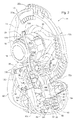
- Fig. 2
- is a perspective, left side view of one of the knotter assemblies shown in
Fig. 1 . - Fig. 3
- is a left front perspective view of the knotter assembly shown in
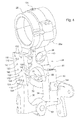
Fig. 2 . - Fig. 4
- is a left rear perspective view of a central region of the knotter frame showing an inlet passage leading to, and outlet passages leading from the mounting face for the lubricant distribution valve.
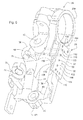
- Fig. 5
- is a left front perspective view of a major portion of the knotter frame showing the mounting face for the lubricant distribution valve, and in dotted lines respectively showing two internal passages having first ends at the mounting face and second ends respectively at the bore for receiving the knife arm shaft and at the upper section of the bore for receiving the bill hook spindle.
- Fig. 6
- is a perspective view of the progressive lubricant distribution valve showing its mounting face containing lubricant inlet and outlet passages for being placed in register with corresponding passages located at the corresponding mounting face provided at the left side of the knotter frame.
- Referring now to
Fig. 1 , there is shown a portion of aknotter arrangement 10 for a large square baler including aknotter drive shaft 12 supported at its opposite ends, in a manner not shown, for rotation about a horizontal transverse axis. Sixidentical knotter assemblies 14 are mounted at equally spaced locations along theshaft 12. It could be more or less than six assemblies. - Referring now also to
Figs 2 and3 , it can be seen that eachknotter assembly 14 includes adrive gear 16 having an integral, leftwardly projectingcylindrical hub 18 received on, and keyed for rotation with, thedrive shaft 12. Thedrive gear 16 further includes a pair of radially outer, annularly spacedgear tooth segments gear tooth segments - Each
knotter assembly 14 further includes aknotter frame 24 having an upper end defined by acylindrical sleeve 26 received about theknotter gear hub 18 so as to permit thehub 18 to rotate relative to thesleeve 26. A major portion of theframe 24 comprises a one-piece casting including an upper end defining alower half 28a of thesleeve 26 and to which anupper half 28b of the sleeve is secured by a pair ofbolts 30 projecting downwardly through holes provided in a first pair of lugs provided at opposite sides of theupper sleeve half 28b and being threaded into respective holes provided in a second pair of lugs provided at opposite sides of thelower sleeve half 28a. Thesleeve 26 is captured between a shoulder provided on thegear 14 about thehub 18 and asnap ring 32 received in an annular ring groove provided in thehub 18. - Joined between the
lower sleeve half 28a and right andleft legs frame 24 is amiddle frame section 38 containing a bore 40 (seeFigs. 4 and5 ), which as viewed inFigs. 1 and2 , is disposed along an upwardly and rearwardly inclined axis which extends perpendicular to the axis of thehub 18. Aknife arm 42 is joined to aknife arm shaft 44 which projects rearwardly through, and is mounted for pivoting within thebore 40. Theshaft 44 is held in place by asnap ring 46 received in an annular snap ring groove provided in a rear end region of theshaft 44. As viewed inFig. 2 , theknife arm 42 extends rightwardly beyond theshaft 44 and terminates at stub shaft carrying aroller 47 engaged with acam surface 48 formed on thegear 16. - The
knotter frame 24 further includes acylindrical ring 49 located between and joined to lower end regions of thelegs ring 49 containing a bore 50 (seeFig. 4 ) having the same orientation as thebore 40. Atwine disk 52 is fixed to a forward end region of adrive spindle 54 projecting rearwardly through, and being mounted for rotation within, thebore 50. Agear 56 is received on a rear end region of thespindle 54 and is retained there by across pin 58 received in aligned bores provided in thegear 56 andspindle 54. Theright leg 34 includes a rearwardlyoffset region 60 which extends along theleg 34 from themiddle section 38 to a location approximately at a level equal to that of a top of thering 48. Extending lengthwise through theoffset leg region 60 is an upright bore 61 (Fig. 4 ) disposed along an axis extending perpendicular to the axis of thebore 50. Aworm gear spindle 62 extends through, and is mounted for rotation within thebore 61 and has agear 64 fixed to its upper end and located for meshing with theinner gear segments worm gear 66 secured to its lower end by anut 68 threaded onto a threaded lower end region of thespindle 62, with theworm gear 66 being meshed with the twinedisk spindle gear 56. - As can be seen in
Fig. 3 , themiddle section 38 of theframe 24 includes a forwardly projectingregion 69 spaced vertically above a forwardly projectingregion 70 of theleg 34. Theregions lower sections 71 and 72 (seeFig. 5 ) of an upright bore in which is located abillhook spindle 74 having adrive gear 76 mounted thereon in the space between theframe regions outer gear segments gear 16. Mounted to a lower end of thespindle 74 is abillhook 78. - Up to this point, what has been described is substantially that which is known in the prior art.
- The present invention relates to a lubrication system 80 (
Fig. 1 ) including apump 82, which is preferably a fixed displacement gear pump, having an inlet coupled to alubricant source 84 and an outlet coupled to a lubricantdistribution manifold block 86 which divides the flow equally among sixfluid lines 88a - 88f, respectively. Each of thefluid lines 88a - 88f is coupled to alubricant inlet passage 90 provided in a respective one of theknotter frames 24, with each inlet passage 90 (Figs. 2 and4 ) being defined by a blind bore extending forwardly from a rear end spaced to the left of, and slightly above the height of, the bore 40 (seeFig. 4 ). While not shown, a T-fitting could be provided at eachinlet passage 90 with the stem of the T being coupled to thepassage 90, and with opposite ends of the head of the T being respectively coupled to one of thelubricant distribution lines 88a - 88f and with a grease zerk, the latter being operable for being coupled directly to a grease gun for supplying lubricant to a givenknotter frame 24 as may be desirable in the event that one of the rotating parts supported by the knotter frame has been replaced and needs lubricant before being put into service. - The
middle section 38 and upper part of theleft leg 36 of theknotter frame 24 are jointly provided with a substantially vertical, leftwardly facing flat rectangular mounting face 92 (seeFigs. 4 and5 ). A lubricant distribution valve 94 (seeFigs. 2 and6 ) includes avalve body 96 which is rectangular in cross section and has aplanar mounting face 98 shaped complimentary to, and clamped against, themounting face 92 of theknotter frame 24 by an upper pair ofmounting bolts 100 extending through respective holes provided in upper corner regions of thevalve body 96 and threaded intoholes 102 provided in themounting face 92, and by a lower pair ofmounting bolts 104 extending through respective holes provided in a lower region of thevalve body 96 and threaded intoholes 106 provided in a lower region of themounting face 92. A pilot pin 108 (seeFig. 6 ) is located between the lower pair ofbolts 104 and is received in apilot hole 110 provided in themounting face 92 between the threadedholes 106. As considered inFigs. 2 and3 , thevalve body 96 contains four fore-and-aft extending valve bore arrangements (not visible) spaced vertically from each other and having opposite front and rear ends respectively closed by front and rear threadedplugs 111, these bore arrangements containing pressure responsive valve elements (not shown) which operate in a series progressive fashion, as is known in the art (see, for example,U.S. Patent No. 5,810,115, granted 22 September 1998 ), to distribute lubricant received by thevalve 94 from thepassage 90 to various lubrication points of theknotter arrangement 14, in a manner described below in further detail. - Referring now also to
Fig. 4 , it can be seen or understood that thelubricant inlet passage 90 is coplanar with, and coupled to, the upper valve bore of thedistribution valve 94 by way of across passage 112 which is provided in theknotter frame 24 so as to extend between theinlet passage 90 and the knotter framevalve mounting face 92, with thecross passage 112 being in register with an end of alubricant inlet passage 114 provided in thevalve body 96 so as to extend between the upper valve bore and themounting face 98. - Associated with each
knotter frame 24 is a lubricant distribution passage arrangement for routing lubricant discharged by thelubricant distribution valve 94 to various lubrication points at the respective interfaces between thesleeve 26 andhub 18, between theworm gear spindle 62 and itsassociated bore 61, between theknife arm shaft 44 and thebore 40, between the upper and lower parts of thebillhook spindle 74 and of the upper andlower bore sections twine disk spindle 54 and bore 50. The lubricant distribution passage arrangement includes both distribution passages extending entirely internally of theframe 24 between thevalve 94 and a respective lubrication point, and a plurality of distribution passages, each composed of intake and delivery passage segments, respectively coupled directly to thevalve 94 and a given distribution point, and to each other by an external distribution line. - Specifically, with reference to
Fig. 5 , it can be seen that a knife arm shaftlubricant distribution passage 116 is provided entirely within theknotter frame 24 and extends between an upper front location of thevalve mounting face 92 and a central location along the length of the knife arm shaft bore 40. The end of thepassage 116 at theface 92 is in register with an upperfront outlet passage 118 provided in thevalve body 96 so as to extend between the upper valve bore arrangement and themounting face 98. Also located entirely within theknotter frame 24 is an upper billhook spindlelubricant distribution passage 120 which extends between a front location of thevalve mounting face 92 disposed vertically below thepassage 116 and a central location between opposite ends of theupper section 71 of the mounting bore for thebillhook spindle 74. Thevalve body 98 is provided with anoutlet passage 122 having an end at themounting face 98 which is in register with the end of thedistribution passage 120 at themounting face 92, theoutlet passage 122 being connected to the second valve bore arrangement from the top of thevalve body 96. - Considering
Figs. 2 and4 together, a gear hub lubricant distribution passage is provided which comprises a gear hublubricant distribution line 124, located exteriorly of theknotter frame 24 and having opposite ends respectively coupled, as byfittings intake passage segment 130 provided in an upper location of theframe leg 36 and adelivery passage segment 131 which extends vertically through the top of thesleeve 26. Themounting face 92 contains across passage 132 coupled to theintake passage segment 130 and being in register with anoutlet passage 134 provided in thevalve body 96. - A twine disk spindle lubricant distribution passage is provided which comprises a worm gear spindle
lubricant distribution line 136 having opposite ends respectively coupled, as byfittings intake passage segment 142, located in theframe leg 36 below thepassage segment 130, and adelivery passage segment 144 extending to the wormgear spindle bore 61 from a location in a central rear surface of therearward projection 60 of theright frame leg 34. Themounting face 92 contains across bore 146 coupled to theintake passage segment 142 and being in register with anoutlet passage 148 provided in thevalve body 96. - Considering now also
Figs. 3 and5 , a billhook spindle section lubricant distribution passage is provided which comprises a lower billhook spindlelubricant distribution line 150 having opposite ends respectively coupled, as byfittings intake passage segment 156, which is aligned with the upper rearintake passage segment 130, and to adelivery passage segment 158 extending through theforward projection 70 of theright frame leg 34. Themounting face 92 contains across passage 160 coupled to theintake passage segment 156 and being in register with anoutlet passage 162 provided in thevalve body 96. - A twine disk spindle lubricant distribution passage includes a twine disk spindle
lubricant distribution line 164 having opposite ends respectively coupled, as byfittings intake passage segment 170, which is aligned with the lowerrear passage segment 142, and to adelivery passage segment 171 extending vertically in thering 49 to the twine disk spindle bore 50. Across passage 172 extends between theintake passage segment 170 and themounting face 92 and is in register with anoutlet passage 174 provided in thevalve body 96. - As stated above, the
lubricant distribution valve 94 is preferably a series progressive divider valve containing valve elements (not shown) which operate, in response to pressure, to sequentially deliver lubricant to the two internallubricant distribution passages knotter frame 24 respectively to the lubrication points for theknife arm shaft 44 and upper region of thebillhook spindle 74, and to the four lubricantdistribution intake passages lubricant distribution lines gear hub 18, theworm gear spindle 62, the lower region of thebillhook spindle 74 and thetwine disk spindle 54. Thus, it will be appreciated that theknotter frame 24 not only serves as a reservoir for lubricant but also serves as a manifold which distributes lubrication to each lubrication point of theknotter assembly 14. - Further, it will be appreciated that even though the
distribution lines knotter frame 24, they are rigid and move in concert with theframe 24 when it is pivoted upwardly to a service position and, therefore, there is no possibility that thelines - The assembly of a
hub 18 andsleeve 26 of theknotter frame 26, theknife arm shaft 44, thespindle 62 of aworm gear 66, thespindle 54 of atwine disk 52 or the billhook spindle 74 a understood to be knotter elements to be lubricated. - Having described the preferred embodiment, it will become apparent that various modifications can be made without departing from the scope of the invention as defined in the accompanying claims.
Claims (6)
- Knotter arrangement (10) having at least one knotter assembly (14) with a knotter frame (24), said knotter frame (24) having multiple lubrication points assigned to moveable knotter elements, and having a lubrication system (80) with a least one fluid line (88a - 88f) supplying lubricant to the knotter assembly (14), characterized by a lubricant distribution valve (94) connected to the knotter frame (24) receiving lubricant via the fluid line (88a - 88f) and distributing it to the lubrication points via lubricant distribution passages (116, 120, 130, 142, 156, 170).
- Knotter arrangement (10) according to claim 1, characterized in that said knotter elements are at least one of an assembly of a hub (18) and sleeve (26) of the knotter frame (24), a knife arm shaft (44), a spindle (62) of a worm gear (66), a spindle (54) of a twine disk (52) or a billhook spindle (74).
- Knotter arrangement according to claim 1 or 2, characterized in that at least one of said lubricant distribution passages (116, 120) is located entirely within said knotter frame (24).
- Knotter arrangement according to one or more of the preceding claims, characterized by at least one lubricant distribution line (124, 136, 150, 164) being located exteriorly of said knotter frame (24) and being connected with one end to a lubricant outlet passage (118, 122, 148, 162) of said valve body (96) and with another end to a delivery passage segment (131, 144, 158, 171) at the lubrication point.
- Knotter arrangement according to one or more of the preceding claims, characterized by an intake passage segment (130, 142, 156, 170) in the knotter frame (24) between the valve body (96) and a lubricant distribution line (124, 136, 150, 164).
- Knotter arrangement according to one or more of the preceding claims, characterized by a mounting face (92) on the knotter frame (24) with passages (112, 116, 120, 132, 146, 160, 172) mating with passages (114, 118, 122, 134, 148, 162, 174) in the valve body (96).
Applications Claiming Priority (1)
| Application Number | Priority Date | Filing Date | Title |
|---|---|---|---|
| US12/480,278 US7752959B1 (en) | 2009-06-08 | 2009-06-08 | Knotter frame serving as lubrication manifold |
Publications (2)
| Publication Number | Publication Date |
|---|---|
| EP2260693A1 true EP2260693A1 (en) | 2010-12-15 |
| EP2260693B1 EP2260693B1 (en) | 2013-03-27 |
Family
ID=42313998
Family Applications (1)
| Application Number | Title | Priority Date | Filing Date |
|---|---|---|---|
| EP10164720A Active EP2260693B1 (en) | 2009-06-08 | 2010-06-02 | Knotter Arrangement |
Country Status (2)
| Country | Link |
|---|---|
| US (1) | US7752959B1 (en) |
| EP (1) | EP2260693B1 (en) |
Cited By (2)
| Publication number | Priority date | Publication date | Assignee | Title |
|---|---|---|---|---|
| WO2020128663A1 (en) * | 2018-12-21 | 2020-06-25 | Agco Corporation | Quick-release lock for baler knotter head |
| EP3932184A1 (en) * | 2020-07-01 | 2022-01-05 | Deere & Company | Intermittent knotter gear |
Families Citing this family (8)
| Publication number | Priority date | Publication date | Assignee | Title |
|---|---|---|---|---|
| US9057284B2 (en) | 2012-04-30 | 2015-06-16 | United Technologies Corporation | Manifold for geared turbofan engine |
| CN104602509B (en) * | 2012-06-14 | 2018-01-19 | 腊斯佩系统技术有限公司 | Twine knotter |
| PL3096600T3 (en) * | 2014-01-22 | 2019-08-30 | Agco Corporation | Single cam double bow knotter for baler |
| DE202015002432U1 (en) * | 2015-03-19 | 2016-06-21 | Rasspe Systemtechnik GmbH | Yarn knotter with central lubrication |
| WO2016155364A1 (en) * | 2015-04-03 | 2016-10-06 | 江苏大学 | Knotting device driven by two toothed discs |
| BE1024810B1 (en) * | 2017-05-02 | 2018-07-03 | Cnh Industrial Belgium Nv | IMPROVEMENTS IN A BUTTON SYSTEM FOR A BALL PRESS |
| BE1024808B1 (en) * | 2017-05-02 | 2018-07-03 | Cnh Industrial Belgium Nv | BUTTON SYSTEM FOR A BALEN PRESS |
| US12302797B1 (en) * | 2023-11-07 | 2025-05-20 | Great Plains Manufacturing, Inc. | Locking mechanism for knotter assemblies |
Citations (5)
| Publication number | Priority date | Publication date | Assignee | Title |
|---|---|---|---|---|
| US2180106A (en) * | 1938-04-08 | 1939-11-14 | Int Harvester Co | Binder |
| DE8914092U1 (en) * | 1989-11-29 | 1990-02-15 | B. Strautmann & Söhne GmbH u. Co, 4518 Bad Laer | Loading wagon with central lubrication of lubrication points on pressing elements |
| DE19528658A1 (en) * | 1995-08-04 | 1997-02-06 | Fortschritt Erntemaschinen | System for controlling periodic cleaning and lubrication of agricultural crop esp. hay baling machine - by using sensor and baling mechanism to switch blowers and lubricator |
| US5810115A (en) | 1996-10-31 | 1998-09-22 | Lubriquip, Inc. | Pressure bypass accessory for a series progressive divider valve |
| US20020088216A1 (en) * | 2001-01-09 | 2002-07-11 | Horejsi Michael J. | Automatic on-board lubrication system for cotton harvesting machines |
Family Cites Families (2)
| Publication number | Priority date | Publication date | Assignee | Title |
|---|---|---|---|---|
| DE2741785C2 (en) * | 1977-09-16 | 1983-10-20 | Karl Mayer Textil-Maschinen-Fabrik Gmbh, 6053 Obertshausen | Knotters for winding machines |
| US4817519A (en) * | 1986-10-10 | 1989-04-04 | Stanwich Holdings, Inc. | Wire feed and tensioning apparatus |
-
2009
- 2009-06-08 US US12/480,278 patent/US7752959B1/en active Active
-
2010
- 2010-06-02 EP EP10164720A patent/EP2260693B1/en active Active
Patent Citations (5)
| Publication number | Priority date | Publication date | Assignee | Title |
|---|---|---|---|---|
| US2180106A (en) * | 1938-04-08 | 1939-11-14 | Int Harvester Co | Binder |
| DE8914092U1 (en) * | 1989-11-29 | 1990-02-15 | B. Strautmann & Söhne GmbH u. Co, 4518 Bad Laer | Loading wagon with central lubrication of lubrication points on pressing elements |
| DE19528658A1 (en) * | 1995-08-04 | 1997-02-06 | Fortschritt Erntemaschinen | System for controlling periodic cleaning and lubrication of agricultural crop esp. hay baling machine - by using sensor and baling mechanism to switch blowers and lubricator |
| US5810115A (en) | 1996-10-31 | 1998-09-22 | Lubriquip, Inc. | Pressure bypass accessory for a series progressive divider valve |
| US20020088216A1 (en) * | 2001-01-09 | 2002-07-11 | Horejsi Michael J. | Automatic on-board lubrication system for cotton harvesting machines |
Cited By (4)
| Publication number | Priority date | Publication date | Assignee | Title |
|---|---|---|---|---|
| WO2020128663A1 (en) * | 2018-12-21 | 2020-06-25 | Agco Corporation | Quick-release lock for baler knotter head |
| US11666003B2 (en) | 2018-12-21 | 2023-06-06 | Agco Corporation | Quick-release lock for baler knotter head |
| EP3932184A1 (en) * | 2020-07-01 | 2022-01-05 | Deere & Company | Intermittent knotter gear |
| US11606908B2 (en) | 2020-07-01 | 2023-03-21 | Deere & Company | Intermittent knotter gear |
Also Published As
| Publication number | Publication date |
|---|---|
| US7752959B1 (en) | 2010-07-13 |
| EP2260693B1 (en) | 2013-03-27 |
Similar Documents
| Publication | Publication Date | Title |
|---|---|---|
| EP2260693B1 (en) | Knotter Arrangement | |
| DE69933901T2 (en) | Fuel injection pump | |
| DE202007005273U1 (en) | Bearing arrangement and metering valve and suction device for this purpose | |
| US10190553B2 (en) | Pumping unit for feeding fuel, preferably diesel fuel, from a storage tank to an internal combustion engine | |
| DE2325614A1 (en) | LUBRICANT SUPPLY SYSTEM FOR EMERGENCY OPERATION | |
| DE102011082729A1 (en) | High-pressure fuel pump for a fuel injection system and pump arrangement | |
| DE202007008531U1 (en) | Device for supplying lubricant and bearing arrangement hereby | |
| DE102016010746A1 (en) | Fuel pump mounting structure for a motor | |
| DE102006035378B4 (en) | Vehicle brake device | |
| DE102013100845B4 (en) | Fuel feed pump | |
| DE102012222753B4 (en) | Gas pump with sealing oil groove | |
| DE2059836A1 (en) | Axial piston unit | |
| CN110259930A (en) | The efficient enforced lubricating system of coalcutter with circulation lubricating function | |
| DE1625896B1 (en) | Plunger piston with a pressure oil lubrication system supplied by the connecting rod | |
| US10349583B2 (en) | Twine knotter with central lubrication | |
| DE717313C (en) | Spray gun for paint or similar spray material | |
| DE102012218075A1 (en) | High-pressure pump, particularly high-pressure fuel pump for internal combustion engine, comprises pump cylinder, in which pump piston is movably arranged, and oil pump arranged in addition to high-pressure pump, which is driven by camshaft | |
| CN212131989U (en) | Centralized lubricating system and engineering machinery | |
| EP2604908A1 (en) | Lubricant system and wind turbine | |
| DE102017218730A1 (en) | High-pressure fuel pump | |
| DE4433277B4 (en) | Oil system of an internal combustion engine | |
| DE102005011963B4 (en) | bearing arrangement | |
| KR102519656B1 (en) | Engine with cylinder block embedding oil pump | |
| DE102010031154B4 (en) | A fluid delivery pump comprising first and second contacting drive shaft seals having a variably adjustable throttle passage between the first and second driveshaft seals | |
| DE102024120000B4 (en) | Powertrain unit for electrically powered motor vehicle |
Legal Events
| Date | Code | Title | Description |
|---|---|---|---|
| PUAI | Public reference made under article 153(3) epc to a published international application that has entered the european phase |
Free format text: ORIGINAL CODE: 0009012 |
|
| AK | Designated contracting states |
Kind code of ref document: A1 Designated state(s): AL AT BE BG CH CY CZ DE DK EE ES FI FR GB GR HR HU IE IS IT LI LT LU LV MC MK MT NL NO PL PT RO SE SI SK SM TR |
|
| AX | Request for extension of the european patent |
Extension state: BA ME RS |
|
| 17P | Request for examination filed |
Effective date: 20110615 |
|
| GRAP | Despatch of communication of intention to grant a patent |
Free format text: ORIGINAL CODE: EPIDOSNIGR1 |
|
| RIC1 | Information provided on ipc code assigned before grant |
Ipc: F16N 7/38 20060101ALI20120924BHEP Ipc: A01D 69/12 20060101ALI20120924BHEP Ipc: A01F 15/14 20060101AFI20120924BHEP |
|
| GRAS | Grant fee paid |
Free format text: ORIGINAL CODE: EPIDOSNIGR3 |
|
| GRAA | (expected) grant |
Free format text: ORIGINAL CODE: 0009210 |
|
| AK | Designated contracting states |
Kind code of ref document: B1 Designated state(s): AL AT BE BG CH CY CZ DE DK EE ES FI FR GB GR HR HU IE IS IT LI LT LU LV MC MK MT NL NO PL PT RO SE SI SK SM TR |
|
| REG | Reference to a national code |
Ref country code: GB Ref legal event code: FG4D |
|
| REG | Reference to a national code |
Ref country code: CH Ref legal event code: EP |
|
| REG | Reference to a national code |
Ref country code: AT Ref legal event code: REF Ref document number: 602760 Country of ref document: AT Kind code of ref document: T Effective date: 20130415 |
|
| REG | Reference to a national code |
Ref country code: IE Ref legal event code: FG4D |
|
| REG | Reference to a national code |
Ref country code: DE Ref legal event code: R096 Ref document number: 602010005730 Country of ref document: DE Effective date: 20130529 |
|
| PG25 | Lapsed in a contracting state [announced via postgrant information from national office to epo] |
Ref country code: LT Free format text: LAPSE BECAUSE OF FAILURE TO SUBMIT A TRANSLATION OF THE DESCRIPTION OR TO PAY THE FEE WITHIN THE PRESCRIBED TIME-LIMIT Effective date: 20130327 Ref country code: NO Free format text: LAPSE BECAUSE OF FAILURE TO SUBMIT A TRANSLATION OF THE DESCRIPTION OR TO PAY THE FEE WITHIN THE PRESCRIBED TIME-LIMIT Effective date: 20130627 Ref country code: SE Free format text: LAPSE BECAUSE OF FAILURE TO SUBMIT A TRANSLATION OF THE DESCRIPTION OR TO PAY THE FEE WITHIN THE PRESCRIBED TIME-LIMIT Effective date: 20130327 Ref country code: BG Free format text: LAPSE BECAUSE OF FAILURE TO SUBMIT A TRANSLATION OF THE DESCRIPTION OR TO PAY THE FEE WITHIN THE PRESCRIBED TIME-LIMIT Effective date: 20130627 |
|
| REG | Reference to a national code |
Ref country code: AT Ref legal event code: MK05 Ref document number: 602760 Country of ref document: AT Kind code of ref document: T Effective date: 20130327 |
|
| REG | Reference to a national code |
Ref country code: LT Ref legal event code: MG4D |
|
| PG25 | Lapsed in a contracting state [announced via postgrant information from national office to epo] |
Ref country code: GR Free format text: LAPSE BECAUSE OF FAILURE TO SUBMIT A TRANSLATION OF THE DESCRIPTION OR TO PAY THE FEE WITHIN THE PRESCRIBED TIME-LIMIT Effective date: 20130628 Ref country code: SI Free format text: LAPSE BECAUSE OF FAILURE TO SUBMIT A TRANSLATION OF THE DESCRIPTION OR TO PAY THE FEE WITHIN THE PRESCRIBED TIME-LIMIT Effective date: 20130327 Ref country code: LV Free format text: LAPSE BECAUSE OF FAILURE TO SUBMIT A TRANSLATION OF THE DESCRIPTION OR TO PAY THE FEE WITHIN THE PRESCRIBED TIME-LIMIT Effective date: 20130327 Ref country code: FI Free format text: LAPSE BECAUSE OF FAILURE TO SUBMIT A TRANSLATION OF THE DESCRIPTION OR TO PAY THE FEE WITHIN THE PRESCRIBED TIME-LIMIT Effective date: 20130327 |
|
| REG | Reference to a national code |
Ref country code: NL Ref legal event code: VDEP Effective date: 20130327 |
|
| PG25 | Lapsed in a contracting state [announced via postgrant information from national office to epo] |
Ref country code: HR Free format text: LAPSE BECAUSE OF FAILURE TO SUBMIT A TRANSLATION OF THE DESCRIPTION OR TO PAY THE FEE WITHIN THE PRESCRIBED TIME-LIMIT Effective date: 20130327 Ref country code: BE Free format text: LAPSE BECAUSE OF FAILURE TO SUBMIT A TRANSLATION OF THE DESCRIPTION OR TO PAY THE FEE WITHIN THE PRESCRIBED TIME-LIMIT Effective date: 20130327 |
|
| PG25 | Lapsed in a contracting state [announced via postgrant information from national office to epo] |
Ref country code: PT Free format text: LAPSE BECAUSE OF FAILURE TO SUBMIT A TRANSLATION OF THE DESCRIPTION OR TO PAY THE FEE WITHIN THE PRESCRIBED TIME-LIMIT Effective date: 20130729 Ref country code: ES Free format text: LAPSE BECAUSE OF FAILURE TO SUBMIT A TRANSLATION OF THE DESCRIPTION OR TO PAY THE FEE WITHIN THE PRESCRIBED TIME-LIMIT Effective date: 20130708 Ref country code: IS Free format text: LAPSE BECAUSE OF FAILURE TO SUBMIT A TRANSLATION OF THE DESCRIPTION OR TO PAY THE FEE WITHIN THE PRESCRIBED TIME-LIMIT Effective date: 20130727 Ref country code: SK Free format text: LAPSE BECAUSE OF FAILURE TO SUBMIT A TRANSLATION OF THE DESCRIPTION OR TO PAY THE FEE WITHIN THE PRESCRIBED TIME-LIMIT Effective date: 20130327 Ref country code: EE Free format text: LAPSE BECAUSE OF FAILURE TO SUBMIT A TRANSLATION OF THE DESCRIPTION OR TO PAY THE FEE WITHIN THE PRESCRIBED TIME-LIMIT Effective date: 20130327 Ref country code: AT Free format text: LAPSE BECAUSE OF FAILURE TO SUBMIT A TRANSLATION OF THE DESCRIPTION OR TO PAY THE FEE WITHIN THE PRESCRIBED TIME-LIMIT Effective date: 20130327 Ref country code: CZ Free format text: LAPSE BECAUSE OF FAILURE TO SUBMIT A TRANSLATION OF THE DESCRIPTION OR TO PAY THE FEE WITHIN THE PRESCRIBED TIME-LIMIT Effective date: 20130327 Ref country code: RO Free format text: LAPSE BECAUSE OF FAILURE TO SUBMIT A TRANSLATION OF THE DESCRIPTION OR TO PAY THE FEE WITHIN THE PRESCRIBED TIME-LIMIT Effective date: 20130327 Ref country code: NL Free format text: LAPSE BECAUSE OF FAILURE TO SUBMIT A TRANSLATION OF THE DESCRIPTION OR TO PAY THE FEE WITHIN THE PRESCRIBED TIME-LIMIT Effective date: 20130327 |
|
| PG25 | Lapsed in a contracting state [announced via postgrant information from national office to epo] |
Ref country code: PL Free format text: LAPSE BECAUSE OF FAILURE TO SUBMIT A TRANSLATION OF THE DESCRIPTION OR TO PAY THE FEE WITHIN THE PRESCRIBED TIME-LIMIT Effective date: 20130327 Ref country code: CY Free format text: LAPSE BECAUSE OF FAILURE TO SUBMIT A TRANSLATION OF THE DESCRIPTION OR TO PAY THE FEE WITHIN THE PRESCRIBED TIME-LIMIT Effective date: 20130327 |
|
| PG25 | Lapsed in a contracting state [announced via postgrant information from national office to epo] |
Ref country code: DK Free format text: LAPSE BECAUSE OF FAILURE TO SUBMIT A TRANSLATION OF THE DESCRIPTION OR TO PAY THE FEE WITHIN THE PRESCRIBED TIME-LIMIT Effective date: 20130327 Ref country code: MC Free format text: LAPSE BECAUSE OF FAILURE TO SUBMIT A TRANSLATION OF THE DESCRIPTION OR TO PAY THE FEE WITHIN THE PRESCRIBED TIME-LIMIT Effective date: 20130327 |
|
| PLBE | No opposition filed within time limit |
Free format text: ORIGINAL CODE: 0009261 |
|
| STAA | Information on the status of an ep patent application or granted ep patent |
Free format text: STATUS: NO OPPOSITION FILED WITHIN TIME LIMIT |
|
| 26N | No opposition filed |
Effective date: 20140103 |
|
| REG | Reference to a national code |
Ref country code: DE Ref legal event code: R097 Ref document number: 602010005730 Country of ref document: DE Effective date: 20140103 |
|
| REG | Reference to a national code |
Ref country code: CH Ref legal event code: PL |
|
| GBPC | Gb: european patent ceased through non-payment of renewal fee |
Effective date: 20140602 |
|
| PG25 | Lapsed in a contracting state [announced via postgrant information from national office to epo] |
Ref country code: MT Free format text: LAPSE BECAUSE OF FAILURE TO SUBMIT A TRANSLATION OF THE DESCRIPTION OR TO PAY THE FEE WITHIN THE PRESCRIBED TIME-LIMIT Effective date: 20130327 |
|
| PG25 | Lapsed in a contracting state [announced via postgrant information from national office to epo] |
Ref country code: CH Free format text: LAPSE BECAUSE OF NON-PAYMENT OF DUE FEES Effective date: 20140630 Ref country code: LI Free format text: LAPSE BECAUSE OF NON-PAYMENT OF DUE FEES Effective date: 20140630 |
|
| PG25 | Lapsed in a contracting state [announced via postgrant information from national office to epo] |
Ref country code: SM Free format text: LAPSE BECAUSE OF FAILURE TO SUBMIT A TRANSLATION OF THE DESCRIPTION OR TO PAY THE FEE WITHIN THE PRESCRIBED TIME-LIMIT Effective date: 20130327 Ref country code: GB Free format text: LAPSE BECAUSE OF NON-PAYMENT OF DUE FEES Effective date: 20140602 |
|
| PG25 | Lapsed in a contracting state [announced via postgrant information from national office to epo] |
Ref country code: TR Free format text: LAPSE BECAUSE OF FAILURE TO SUBMIT A TRANSLATION OF THE DESCRIPTION OR TO PAY THE FEE WITHIN THE PRESCRIBED TIME-LIMIT Effective date: 20130327 |
|
| PG25 | Lapsed in a contracting state [announced via postgrant information from national office to epo] |
Ref country code: MK Free format text: LAPSE BECAUSE OF FAILURE TO SUBMIT A TRANSLATION OF THE DESCRIPTION OR TO PAY THE FEE WITHIN THE PRESCRIBED TIME-LIMIT Effective date: 20130327 Ref country code: HU Free format text: LAPSE BECAUSE OF FAILURE TO SUBMIT A TRANSLATION OF THE DESCRIPTION OR TO PAY THE FEE WITHIN THE PRESCRIBED TIME-LIMIT; INVALID AB INITIO Effective date: 20100602 Ref country code: LU Free format text: LAPSE BECAUSE OF NON-PAYMENT OF DUE FEES Effective date: 20130602 |
|
| REG | Reference to a national code |
Ref country code: FR Ref legal event code: PLFP Year of fee payment: 7 |
|
| REG | Reference to a national code |
Ref country code: FR Ref legal event code: PLFP Year of fee payment: 8 |
|
| PGFP | Annual fee paid to national office [announced via postgrant information from national office to epo] |
Ref country code: IE Payment date: 20170628 Year of fee payment: 8 |
|
| PGFP | Annual fee paid to national office [announced via postgrant information from national office to epo] |
Ref country code: IT Payment date: 20170622 Year of fee payment: 8 |
|
| REG | Reference to a national code |
Ref country code: FR Ref legal event code: PLFP Year of fee payment: 9 |
|
| PG25 | Lapsed in a contracting state [announced via postgrant information from national office to epo] |
Ref country code: AL Free format text: LAPSE BECAUSE OF FAILURE TO SUBMIT A TRANSLATION OF THE DESCRIPTION OR TO PAY THE FEE WITHIN THE PRESCRIBED TIME-LIMIT Effective date: 20130327 |
|
| REG | Reference to a national code |
Ref country code: IE Ref legal event code: MM4A |
|
| PG25 | Lapsed in a contracting state [announced via postgrant information from national office to epo] |
Ref country code: IT Free format text: LAPSE BECAUSE OF NON-PAYMENT OF DUE FEES Effective date: 20180602 Ref country code: IE Free format text: LAPSE BECAUSE OF NON-PAYMENT OF DUE FEES Effective date: 20180602 |
|
| PGFP | Annual fee paid to national office [announced via postgrant information from national office to epo] |
Ref country code: DE Payment date: 20250521 Year of fee payment: 16 |
|
| PGFP | Annual fee paid to national office [announced via postgrant information from national office to epo] |
Ref country code: FR Payment date: 20250625 Year of fee payment: 16 |