EP2260664B1 - Extension of power headroom reporting - Google Patents
Extension of power headroom reporting Download PDFInfo
- Publication number
- EP2260664B1 EP2260664B1 EP09724253.1A EP09724253A EP2260664B1 EP 2260664 B1 EP2260664 B1 EP 2260664B1 EP 09724253 A EP09724253 A EP 09724253A EP 2260664 B1 EP2260664 B1 EP 2260664B1
- Authority
- EP
- European Patent Office
- Prior art keywords
- power
- power headroom
- headroom report
- report
- positive
- Prior art date
- Legal status (The legal status is an assumption and is not a legal conclusion. Google has not performed a legal analysis and makes no representation as to the accuracy of the status listed.)
- Active
Links
Images

Classifications
-
- H—ELECTRICITY
- H04—ELECTRIC COMMUNICATION TECHNIQUE
- H04W—WIRELESS COMMUNICATION NETWORKS
- H04W52/00—Power management, e.g. Transmission Power Control [TPC] or power classes
- H04W52/04—Transmission power control [TPC]
- H04W52/30—Transmission power control [TPC] using constraints in the total amount of available transmission power
- H04W52/36—Transmission power control [TPC] using constraints in the total amount of available transmission power with a discrete range or set of values, e.g. step size, ramping or offsets
- H04W52/367—Power values between minimum and maximum limits, e.g. dynamic range
-
- H—ELECTRICITY
- H04—ELECTRIC COMMUNICATION TECHNIQUE
- H04W—WIRELESS COMMUNICATION NETWORKS
- H04W52/00—Power management, e.g. Transmission Power Control [TPC] or power classes
- H04W52/04—Transmission power control [TPC]
- H04W52/30—Transmission power control [TPC] using constraints in the total amount of available transmission power
- H04W52/36—Transmission power control [TPC] using constraints in the total amount of available transmission power with a discrete range or set of values, e.g. step size, ramping or offsets
- H04W52/365—Power headroom reporting
-
- H—ELECTRICITY
- H04—ELECTRIC COMMUNICATION TECHNIQUE
- H04W—WIRELESS COMMUNICATION NETWORKS
- H04W72/00—Local resource management
- H04W72/04—Wireless resource allocation
-
- H—ELECTRICITY
- H04—ELECTRIC COMMUNICATION TECHNIQUE
- H04W—WIRELESS COMMUNICATION NETWORKS
- H04W72/00—Local resource management
- H04W72/50—Allocation or scheduling criteria for wireless resources
- H04W72/54—Allocation or scheduling criteria for wireless resources based on quality criteria
- H04W72/542—Allocation or scheduling criteria for wireless resources based on quality criteria using measured or perceived quality
-
- H—ELECTRICITY
- H04—ELECTRIC COMMUNICATION TECHNIQUE
- H04W—WIRELESS COMMUNICATION NETWORKS
- H04W8/00—Network data management
- H04W8/22—Processing or transfer of terminal data, e.g. status or physical capabilities
- H04W8/24—Transfer of terminal data
Definitions
- Certain embodiments of the present invention generally relate to communication technologies.
- certain embodiments of the present invention can be used in wireless communications, and particular in the Long Term Evolution (LTE) of Third Generation Partnership Project (3GPP) and Evolved UMTS (Universal Mobile Telecommunication System) Terrestrial Radio Access Network (Evolved UTRAN or simply EUTRAN).
- LTE Long Term Evolution
- 3GPP Third Generation Partnership Project
- Evolved UMTS Universal Mobile Telecommunication System Terrestrial Radio Access Network
- EUTRAN Universal Mobile Telecommunication System Terrestrial Radio Access Network
- More particularly certain embodiments of the present invention provide an extension of power headroom reporting to be used by each and every user equipment (UE) to allow for a more efficient resource allocation by an evolved Node B (eNodeB).
- UE user equipment
- eNodeB evolved Node B
- LTE Long Term Evolution
- EPS Evolved Packet System
- E-UTRAN Evolved UTRAN
- EPC Evolved Packet Core
- 3GPP Release 8 is expected to be developed further. Much of the standard is expected to be oriented around upgrading UMTS to the fourth generation mobile communications technology, essentially a wireless broadband Internet system with voice and other services, such as data services, built on top.
- One embodiment of the present invention is an apparatus.
- the apparatus includes a processor configured to determine a power headroom report.
- the apparatus also includes a transmitter configured to transmit the headroom report.
- the processor is configured to determine the power headroom report with both positive and negative values of power headroom, as applicable, in which negative values indicate the missing power in dB to fulfill transmission requirements.
- the apparatus includes a receiver configured to receive a power headroom report.
- the apparatus further includes a processor configured to allocate radio network resources based on the power headroom report.
- the processor is configured to obtain both positive and negative values of power headroom from the power headroom report, as applicable, in which negative values indicate the missing power in dB to fulfill transmission requirements.
- a further embodiment of the present invention is a method.
- the method includes determining a power headroom report.
- the method also includes transmitting the headroom report.
- the determining includes determining the power headroom report with both positive and negative values of power headroom, as applicable, in which negative values indicate the missing power in dB to fulfill transmission requirements.
- An additional embodiment of the present invention is also a method.
- the method includes receiving a power headroom report.
- the method also includes allocating radio network resources based on the power headroom report.
- the allocating includes obtaining, from the power headroom report, both positive and negative values of power headroom, as applicable, in which negative values indicate the missing power in dB to fulfill transmission requirements.
- Another embodiment of the present invention is a computer-readable storage medium encoded with instructions configured to control a computer to execute a process.
- the process includes determining a power headroom report.
- the process also includes transmitting the headroom report.
- the determining includes determining the power headroom report with both positive and negative values of power headroom, as applicable, in which negative values indicate the missing power in dB to fulfill transmission requirements.
- a further embodiment of the present invention is a computer-readable storage medium encoded with instructions configured to control a computer to execute a process.
- the process includes receiving a power headroom report.
- the process also includes allocating radio network resources based on the power headroom report.
- the allocating includes obtaining, from the power headroom report, both positive and negative values of power headroom, as applicable, in which negative values indicate the missing power in dB to fulfill transmission requirements.
- the apparatus includes determining means for determining a power headroom report.
- the apparatus also includes transmitting means for transmitting the headroom report.
- the determining means is configured to determine the power headroom report with both positive and negative values of power headroom, as applicable, in which negative values indicate the missing power in dB to fulfill transmission requirements.
- An additional embodiment of the present invention is also an apparatus.
- the apparatus includes receiving means for receiving a power headroom report.
- the apparatus also includes allocating means for allocating radio network resources based on the power headroom report.
- the processor is configured to obtain both positive and negative values of power headroom from the power headroom report, as applicable, in which negative values indicate the missing power in dB to fulfill transmission requirements.
- Certain embodiments of the present invention relate to an extension of power headroom reporting to be used by each and every User Equipment (UE) to allow for a more economic resource allocation by an evolved Node B (eNodeB).
- UE User Equipment
- eNodeB evolved Node B
- the UE can report in a power headroom report the difference between the nominal maximum power and the power at the UE, e.g. the power that the UE would use if it did not apply maximum power limitations.
- This power headroom report describes only the positive difference between nominal maximum transmission power and the currently used power.
- the eNodeB will not have knowledge about the "missing" power at the UE. As a result resources on the air interface are somehow wasted since the scheduler is not aware of how much the UE power budget is exceeded.
- Power headroom reporting can be performed in both directions, e.g. reporting (a) positive headroom if the current transmit power is lower than the nominal maximum transmission power and (b) negative headroom if the required transmit power according to the allocation scheme in terms of number of resource blocks, broadcasted and dedicated offset parameters, path loss estimates, as well as selected modulation and coding scheme and closed-loop power correction values requires higher power than the nominal maximum transmit power.
- the power headroom report is negative if the right part of the min-function in Equation 1 for Physical Uplink Shared Channel (discussed below) exceeds P max . This part includes further terms (offset parameters, path loss estimates, and closed-loop power corrections).
- the right part of the min-function requests a transmission power of 26 dBm.
- P max is set to 23 dBm.
- the extension of power headroom reporting to negative values can be used by the UE to inform the eNodeB about the amount of missing power in dB; eNodeB scheduler to reduce the number of allocated RBs to an optimum bandwidth and/or Adaptive Modulation and Coding (AMC) to adapt the modulation and coding scheme (MCS downgrade) in case of slow AMC, or outer loop link adaptation offset in case of fast AMC; adaptation of the UpLink (UL) power control; reconfiguration of UL sounding channel - if applicable; reconfiguration of signaling resources and power - if applicable; and rescaling of previous measurements - if applicable.
- AMC Adaptive Modulation and Coding
- the currently proposed uplink in LTE uses Single Carrier Frequency Division Multiple Access (SC-FDMA) multiplexing and Quadrature Phase Shift Keying (QPSK) or 16 Quadrature Amplitude Modulation (QAM) (64QAM optional) modulation.
- Power control can be an efficient means to improve the cell edge behavior, to relax the requirements on the intra-cell orthogonality, and to reduce inter-cell interference and power consumption.
- the Power Spectral Density (PSD) can be determined by an open loop power control component calculated at the User Equipment (UE) and a closed loop power control correction transmitted by the eNodeB.
- PSD can be defined as "transmission power per resource block," where a resource block (RB) is the smallest time/frequency unit that can be assigned by the scheduler.
- the setting of the UE transmit power according to 3GPP TS 36.213 is based on broadcasted and dedicated parameters as well as path loss estimates.
- the maximum uplink transmit power is limited by a maximum value P max signaled from the network to the UE and by the capability of the UE according to its UE class.
- the eNodeB can be configured to know at which PSD level the different UEs are operating.
- the PSD can be calculated from the total UE transmission power and the number of assigned physical resources. This information can be important for performing correct radio resource management and link quality control decisions at the eNodeB, especially for the adaptation of the modulation and coding scheme, UpLink (UL) power control and resource assignment.
- UL UpLink
- An imprecise knowledge of the PSD used by a specific UE could e.g. cause the allocation of an excessively high transmission bandwidth, thus resulting in a lower Signal to Interference plus Noise Ratio (SINR) than expected.
- SINR Signal to Interference plus Noise Ratio
- Information on the PSD used at the UE is expected to be obtained from the power control headroom reports, which are current topics in 3GPP standardization.
- the power control headroom is the difference between the nominal maximum transmission power and the power at the UE, e.g . the power that the UE would use if it did not apply maximum power limitations.
- the power control headroom is calculated per Transmission Time Interval (TTI) and it is expected that the UE sends power headroom reports after n closed loop power control commands, if the change of the path loss exceeds a specific threshold since the last power headroom report, if the UE is close to maximum power or if the timer started at previous report has elapsed. Periodic sending of power headroom report is also possible.
- TTI Transmission Time Interval
- 3GPP TS 36.213 defines the UE transmit power for the Physical Uplink Shared Channel (PUSCH) P PUSCH transmission in subframe i by the following equation:
- P PUSCH i min P MAX , 10 log 10 M PUSCH i + P 0 _ PUSCH j + ⁇ ⁇ PL + ⁇ TF TF i + f i dBm
- the UE can report in the power headroom report, the difference between P MAX and the second term of the minimum function in equation 1.
- This power headroom report (in the conventional implementation) describes only the positive difference between nominal maximum transmission power and the currently used power. Using maximum transmit power results in a power headroom of 0 dB but also requiring more power for maintaining the PSD at given allocation would result in a power headroom report of 0 dB.
- the power headroom without extension to negative values would also report the value 0 and the network does not obtain knowledge whether the uplink power is exactly sufficient (the right part of the min-function is equal to P max ) or if power is missing, i.e.
- the right part of the min-function is higher than P max .
- the eNodeB is not expected to have knowledge about the "missing" power at the UE.
- resources on the air interface may be wasted, since the scheduler is not aware of how much the UE power budget is exceeded.
- the power headroom reporting is extended to both directions, e.g. reporting (a) positive headroom if the current transmit power is lower than the nominal maximum transmission power and (b) negative headroom if the required transmit power according to the allocation scheme in terms of number of RBs as well as selected modulation and coding scheme requires higher power than the nominal maximum transmit power.
- the UE can send immediately a Power Headroom Report.
- the UE can, optionally, also be allowed to use only a limited number of resources for submission and can indicate this (or be told of this by, for example, an eNodeB). This may enhance high coverage.
- the UE can reduce the number of RBs for uplink transmission, i.e. the UE can transmit on fewer RBs than scheduled.
- the eNodeB can be informed about this action.
- This option can be enabled or disabled by the network via broadcast message or dedicated signaling.
- the UE can use another, e.g. more robust modulation and coding scheme with lower ⁇ TF and can signal this to the eNodeB. Enabling or disabling of this option can also be controlled by the network.
- At least some of the solutions described in present application allow the scheduler to reduce the resource allocation on the appropriate number of RBs, in a targeted, accurate way.
- radio resource management may have all necessary information to determine in advance the number of RBs to be reduced.
- the assignment of the gained RBs to other connections may become possible immediately, and the performance of LTE can be increased in terms of quality and capacity.
- Certain embodiments of the present invention may result in a shift of the range covered by headroom reporting.
- the power control range in LTE is assumed to be 40 dB. With 6 bits used for signaling 64 power headroom, levels can be defined ranging from +40 dB to -23 dB in steps of 1 dB. This range can be extended, in terms of the lower limit of the range, from currently 0 dB to negative values. An extension to 3 dB can permit Adaptive Transmission Bandwidth (ATB) to reduce the bandwidth by 50%. Larger steps in bandwidth reduction can be provided by extending the range to e.g. -10 dB or -23 dB. This extension for the information of negative power headroom can be used by radio resource management to adapt the modulation scheme e.g.
- a larger negative range can also allow for a higher granularity in each mixture of joint ATB and AMC measures. This is expected to provide sufficient range given by 6 bits for signaling. A shift of the range towards negative values could be similarly handled in case of a reduction of the signaling bits to e.g. 5.
- Certain embodiments of the present invention extend the power headroom report from positive only to positive and negative values, where negative power headroom represents the following situation: the reported negative value indicates the missing power in dB to fulfill the requirements given by current resource allocation and modulation and coding scheme. This knowledge can allow an exact reassignment of the allocated resources and a more economic resource utilization.
- Figure 1 illustrates a system according to an embodiment of the present invention.
- the system includes a first apparatus 100 and a second apparatus 200.
- the first apparatus 100 and the second apparatus 200 can be configured to communicate over a communication link 300, which is illustrated as a direct wireless communication link, though there is no requirement that any connection between the first apparatus 100 and second apparatus 200 be either direct or wireless.
- the first apparatus 100 can include a processor 110, a transmitter 120, a receiver 130, and optionally a memory 140.
- the first apparatus 100 can be, for example, a UE, such as a personal digital assistant, a handheld computer, a cellular telephone, or other communication device.
- the first apparatus can be implemented as a combination of hardware 150 and software 160.
- the hardware 150 can be, for example, a general purpose computer or an Application Specific Integrated Circuit (ASIC).
- the optional memory 140 can be any conventional memory, such as flash Random Access Memory (RAM), a Compact Disk (CD), or a hard drive.
- the processor 110 can be configured to determine a power headroom report.
- the transmitter 120 can be configured to transmit the headroom report.
- the power headroom report itself can be configured to provide both positive and negative values of power headroom according to the determination of the processor, in which negative values indicate the missing power in dB to fulfill transmission requirements such as, for example, the requirements given by at least one of resource allocation, modulation scheme, coding scheme, offset parameters, path loss estimates, or closed-loop power correction values.
- both ... and ... according to the determination it should be understood that in certain embodiments of the present invention, this is implemented by providing a positive value (only) if the determination yields a positive value and a negative value (only) if the determination yields a negative value. It is not necessarily required that both a positive value and a negative value be simultaneously present in a given power report.
- the second apparatus 200 can include a processor 210, a transmitter 220, a receiver 230, and optionally a memory 240.
- the second apparatus 200 can be, for example, a base station, access point, router, or evolved Node B.
- the second apparatus can be implemented as a combination of hardware 250 and software 260.
- the hardware 250 can be, for example, a general purpose computer or an Application Specific Integrated Circuit (ASIC).
- the optional memory 240 can be any conventional memory, such as flash Random Access Memory (RAM), a Compact Disk (CD), or a hard drive.
- the receiver 230 can be configured to receive a power headroom report.
- the processor 210 can be configured to allocate radio network resources based on the power headroom report.
- the power headroom report itself can be configured to provide both positive and negative values of power headroom according to the determination of the processor, in which negative values indicate the missing power in dB to fulfill transmission requirements such as, for example, requirements given by at least one of resource allocation, modulation scheme, coding scheme, offset parameters, path loss estimates, or closed-loop power correction values.
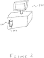
- Figure 2 illustrates a computer-readable medium according to an embodiment of the present invention.
- a computer-readable medium 290 (such as a hard disk drive, CD-Read Only Memory (CD-ROM), or Electronically Programmable ROM (EPROM) - other forms of computer readable media are not excluded) can be encoded with instructions that cause a computer 295 to execute a process when the instructions are executed.
- the instructions can include a power headroom report 297 in which a power headroom on a range that includes negative and positive power headroom is expressible.
- the power headroom report 297 can include a value that is either positive or negative. Whether the value is positive or negative can be determined by processor of, for example, a user equipment.
- the value provided in the power headroom report 297 can instruct the processor of, for example, an eNodeB, to allocate resources in a particular way.
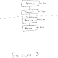
- Figure 3 illustrates a method according to an embodiment of the present invention.
- the method can include determining 310 a power headroom report.
- the method can also include transmitting 320 the headroom report.
- the power headroom report can provide both positive and negative values of power headroom according to the determination, in which negative values indicate the missing power in dB to fulfill transmission requirements such as, for example, requirements given by at least one of resource allocation, modulation scheme, coding scheme, offset parameters, path loss estimates, or closed-loop power correction values.
- This method can be implemented by encoding instructions for performing this method on a computer-readable medium, such that the instructions when execute cause the computer to execute the method as a computer process.
- the method can further include receiving 330 a power headroom report.
- the method can additionally include allocating 340 radio network resources based on the power headroom report.
- the present invention has been described mainly in terms of a user equipment (UE) interacting with an evolved Node B (eNodeB). It should be understood, however, that this implementation is merely an example. Other implementations could be made, such as by substituting personal computers (PCs) for both the UE and the eNodeB. Additionally, though in some places the system is described as containing only a single UE and only a single eNodeB, it should be understood that the system could be implemented with either multiple UEs or multiple eNodeBs or both.
- PCs personal computers
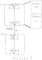
- Figure 4 illustrates a system according to an embodiment of the present invention.
- the system includes a first apparatus 100 and a second apparatus 200.
- the first apparatus 100 and the second apparatus 200 can be configured to communicate over a communication link 300, which is illustrated as a direct communication link, though there is no requirement that any connection between the first apparatus 100 and second apparatus 200 be a direct connection.
- the first apparatus 100 can be implemented as a combination of hardware 150 and software 160.
- the hardware 150 can be, for example, a general purpose computer or an Application Specific Integrated Circuit (ASIC).
- ASIC Application Specific Integrated Circuit
- the second apparatus 200 can be similar constructed.
- the first apparatus 100 can include a determination unit 410 configured to determine a power headroom report.
- the first apparatus can also include a transmission unit 420 configured to transmit the headroom report.
- the power headroom report itself can be configured to provide both positive and negative values of power headroom according to the determination of the determination unit 410, in which negative values indicate the missing power in dB to fulfill transmission requirements such as, for example, requirements given by at least one of resource allocation, modulation scheme, coding scheme, offset parameters, path loss estimates, or closed-loop power correction values.
- this is implemented by providing a positive value (only) if the determination yields a positive value and a negative value (only) if the determination yields a negative value. It is not necessarily required that both a positive value and a negative value be simultaneously present in a given power report.
- the second apparatus 200 can include a reception unit 430 configured to receive a power headroom report.
- the second apparatus 200 can also include an allocation unit 440 configured to allocate radio network resources based on the power headroom report.
- the power headroom report itself can be configured to provide both positive and negative values of power headroom according to the determination of the processor, in which negative values indicate the missing power in dB to fulfill transmission requirements such as, for example, requirements given by at least one of resource allocation, modulation scheme, coding scheme, offset parameters, path loss estimates, or closed-loop power correction values.
- the various units (410, 420, 430, and 440) of the first apparatus 100 and the second apparatus 200 can be implemented in hardware, optionally together with software.
- a general purpose processor can be configured to serve as an allocation unit 440 when it is performing allocation, and the same general purpose processor can serve as a reception unit 430 when it is receiving a signal that includes a power headroom report.
- two or more processors or other devices can be configured to serve as the various units (410, 420, 430, and 440), in particular implementations.
Landscapes
- Engineering & Computer Science (AREA)
- Computer Networks & Wireless Communication (AREA)
- Signal Processing (AREA)
- Mobile Radio Communication Systems (AREA)
- Transmitters (AREA)
Description
- This application claims priority under 35 U.S.C. §119(e) of
U.S. Provisional Patent Application Ser. No. 61/039,707, filed on March 26, 2008 - Certain embodiments of the present invention generally relate to communication technologies. For example, certain embodiments of the present invention can be used in wireless communications, and particular in the Long Term Evolution (LTE) of Third Generation Partnership Project (3GPP) and Evolved UMTS (Universal Mobile Telecommunication System) Terrestrial Radio Access Network (Evolved UTRAN or simply EUTRAN). More particularly certain embodiments of the present invention provide an extension of power headroom reporting to be used by each and every user equipment (UE) to allow for a more efficient resource allocation by an evolved Node B (eNodeB).
- Third Generation Partnership Project (3GPP) Long Term Evolution (LTE), which is a project within the 3GPP to improve the UMTS standard with respect to efficiency, services, costs, new spectrum opportunities and better integration with other open standards. LTE may result in a new evolved Release 8 of the 3GPP standard including extensions and modifications of the UMTS system. The architecture is called EPS (Evolved Packet System) and comprehends E-UTRAN (Evolved UTRAN) on the access side and EPC (Evolved Packet Core) on the core side.
- 3GPP Release 8 is expected to be developed further. Much of the standard is expected to be oriented around upgrading UMTS to the fourth generation mobile communications technology, essentially a wireless broadband Internet system with voice and other services, such as data services, built on top.
- In 3GPP standardization the specification for power headroom reporting for LTE has started and is expected to be defined. Power headroom reporting is currently topic of 3GPP standardization and the described problem has not yet been solved. Document CATT: "Requirements for the UE transmission power headroom (UPH)", 3GPP DRAFT; R4-071574, 3RD GENERATION PARTNERSHIP PROJECT (3GPP), MOBILE COMPETENCE CENTRE ; 650, ROUTE DES LUCIOLES ; F-06921 SOPHIA-ANTIPOLIS CEDEX ; FRANCE, vol. RAN WG4, no. Shanghai, China; 20071016, 16 October 2007 (2007-10-16)discloses the use of a power headroom indicator which is indexed from 0 to 31, representing the power headroom absolute values running from -14dB to 28 dB.
- The invention is embodied in the apparatus of claim 1 (transmitter) and claim 4 (receiver), in the related method claims 8 and 11 and in the computer-readable storage media of claims 15 and 16. [message for the printer: please substitute in the following part of the description the terms "embodiment"/"embodiments" with "aspect"/"aspects"]
- One embodiment of the present invention is an apparatus. The apparatus includes a processor configured to determine a power headroom report. The apparatus also includes a transmitter configured to transmit the headroom report. The processor is configured to determine the power headroom report with both positive and negative values of power headroom, as applicable, in which negative values indicate the missing power in dB to fulfill transmission requirements.
- Another embodiment of the present invention is also an apparatus. The apparatus includes a receiver configured to receive a power headroom report. The apparatus further includes a processor configured to allocate radio network resources based on the power headroom report. The processor is configured to obtain both positive and negative values of power headroom from the power headroom report, as applicable, in which negative values indicate the missing power in dB to fulfill transmission requirements.
- A further embodiment of the present invention is a method. The method includes determining a power headroom report. The method also includes transmitting the headroom report. The determining includes determining the power headroom report with both positive and negative values of power headroom, as applicable, in which negative values indicate the missing power in dB to fulfill transmission requirements.
- An additional embodiment of the present invention is also a method. The method includes receiving a power headroom report. The method also includes allocating radio network resources based on the power headroom report. The allocating includes obtaining, from the power headroom report, both positive and negative values of power headroom, as applicable, in which negative values indicate the missing power in dB to fulfill transmission requirements.
- Another embodiment of the present invention is a computer-readable storage medium encoded with instructions configured to control a computer to execute a process. The process includes determining a power headroom report. The process also includes transmitting the headroom report. The determining includes determining the power headroom report with both positive and negative values of power headroom, as applicable, in which negative values indicate the missing power in dB to fulfill transmission requirements.
- A further embodiment of the present invention is a computer-readable storage medium encoded with instructions configured to control a computer to execute a process. The process includes receiving a power headroom report. The process also includes allocating radio network resources based on the power headroom report. The allocating includes obtaining, from the power headroom report, both positive and negative values of power headroom, as applicable, in which negative values indicate the missing power in dB to fulfill transmission requirements.
- Another embodiment of the present invention is an apparatus. The apparatus includes determining means for determining a power headroom report. The apparatus also includes transmitting means for transmitting the headroom report. The determining means is configured to determine the power headroom report with both positive and negative values of power headroom, as applicable, in which negative values indicate the missing power in dB to fulfill transmission requirements.
- An additional embodiment of the present invention is also an apparatus. The apparatus includes receiving means for receiving a power headroom report. The apparatus also includes allocating means for allocating radio network resources based on the power headroom report. The processor is configured to obtain both positive and negative values of power headroom from the power headroom report, as applicable, in which negative values indicate the missing power in dB to fulfill transmission requirements.
- For proper understanding of the invention, reference should be made to the accompanying drawings, wherein:
-
Figure 1 illustrates a system according to an embodiment of the present invention; -
Figure 2 illustrates a computer-readable medium according to an embodiment of the present invention; and -
Figure 3 illustrates a method according to an embodiment of the present invention. -
Figure 4 illustrates a system according to another embodiment of the present invention. - Certain embodiments of the present invention relate to an extension of power headroom reporting to be used by each and every User Equipment (UE) to allow for a more economic resource allocation by an evolved Node B (eNodeB).
- In such embodiments, the UE can report in a power headroom report the difference between the nominal maximum power and the power at the UE, e.g. the power that the UE would use if it did not apply maximum power limitations. This power headroom report describes only the positive difference between nominal maximum transmission power and the currently used power. Hence, with the current standardization assumption, the eNodeB will not have knowledge about the "missing" power at the UE. As a result resources on the air interface are somehow wasted since the scheduler is not aware of how much the UE power budget is exceeded.
- Power headroom reporting can be performed in both directions, e.g. reporting (a) positive headroom if the current transmit power is lower than the nominal maximum transmission power and (b) negative headroom if the required transmit power according to the allocation scheme in terms of number of resource blocks, broadcasted and dedicated offset parameters, path loss estimates, as well as selected modulation and coding scheme and closed-loop power correction values requires higher power than the nominal maximum transmit power. It should be noted that the power headroom report is negative if the right part of the min-function in
Equation 1 for Physical Uplink Shared Channel (discussed below) exceeds Pmax. This part includes further terms (offset parameters, path loss estimates, and closed-loop power corrections). Example: The right part of the min-function requests a transmission power of 26 dBm. Pmax is set to 23 dBm. The reported power headroom is 23 dBm - 26 dBm = -3 dB. - The extension of power headroom reporting to negative values can be used by the UE to inform the eNodeB about the amount of missing power in dB; eNodeB scheduler to reduce the number of allocated RBs to an optimum bandwidth and/or Adaptive Modulation and Coding (AMC) to adapt the modulation and coding scheme (MCS downgrade) in case of slow AMC, or outer loop link adaptation offset in case of fast AMC; adaptation of the UpLink (UL) power control; reconfiguration of UL sounding channel - if applicable; reconfiguration of signaling resources and power - if applicable; and rescaling of previous measurements - if applicable.
- The currently proposed uplink in LTE uses Single Carrier Frequency Division Multiple Access (SC-FDMA) multiplexing and Quadrature Phase Shift Keying (QPSK) or 16 Quadrature Amplitude Modulation (QAM) (64QAM optional) modulation. Power control can be an efficient means to improve the cell edge behavior, to relax the requirements on the intra-cell orthogonality, and to reduce inter-cell interference and power consumption. Basically, the Power Spectral Density (PSD) can be determined by an open loop power control component calculated at the User Equipment (UE) and a closed loop power control correction transmitted by the eNodeB. PSD can be defined as "transmission power per resource block," where a resource block (RB) is the smallest time/frequency unit that can be assigned by the scheduler. The setting of the UE transmit power according to 3GPP TS 36.213 is based on broadcasted and dedicated parameters as well as path loss estimates. The maximum uplink transmit power is limited by a maximum value Pmax signaled from the network to the UE and by the capability of the UE according to its UE class.
- The eNodeB can be configured to know at which PSD level the different UEs are operating. The PSD can be calculated from the total UE transmission power and the number of assigned physical resources. This information can be important for performing correct radio resource management and link quality control decisions at the eNodeB, especially for the adaptation of the modulation and coding scheme, UpLink (UL) power control and resource assignment. An imprecise knowledge of the PSD used by a specific UE could e.g. cause the allocation of an excessively high transmission bandwidth, thus resulting in a lower Signal to Interference plus Noise Ratio (SINR) than expected. Information on the PSD used at the UE is expected to be obtained from the power control headroom reports, which are current topics in 3GPP standardization.
- The power control headroom is the difference between the nominal maximum transmission power and the power at the UE, e.g. the power that the UE would use if it did not apply maximum power limitations. The power control headroom is calculated per Transmission Time Interval (TTI) and it is expected that the UE sends power headroom reports after n closed loop power control commands, if the change of the path loss exceeds a specific threshold since the last power headroom report, if the UE is close to maximum power or if the timer started at previous report has elapsed. Periodic sending of power headroom report is also possible.
- 3GPP TS 36.213 defines the UE transmit power for the Physical Uplink Shared Channel (PUSCH) PPUSCH transmission in subframe i by the following equation:
-
Equation 1 for Physical Uplink Shared Channel (PUSCH)
- PMAX can be the maximum allowed power configured by higher layers;
- MPUSCH can be the size of the PUSCH resource assignment expressed in number of resource blocks valid for subframe i;
- P0_PUSCH can be an offset parameter defined by Operation and Maintenance (O&M) or additionally influenced by internal calculations;
- α can be a path loss compensation factor adjustable by O&M;
- PL can be the downlink Path Loss (PL) estimate calculated in the UE;
- ΔTF can be a Transport Format (TF) dependent offset; and
- f(i) can represent reporting of closed loop power correction values using accumulation or absolute values, respectively.
- An alternative to
Equation 1 is the following:
Equation 1. Further changes are possible, for example, in which PMAX is defined by PCMAX = MIN(PEMAX, PUMAX), where PEMAX is the maximum allowed power configured by higher layers and defined in 3GPP TS 36.331 and PUMAX is the maximum UE power for the UE power class specified in 3GPP TS 36.101. - The UE can report in the power headroom report, the difference between PMAX and the second term of the minimum function in
equation 1. This power headroom report (in the conventional implementation) describes only the positive difference between nominal maximum transmission power and the currently used power. Using maximum transmit power results in a power headroom of 0 dB but also requiring more power for maintaining the PSD at given allocation would result in a power headroom report of 0 dB. In other words, if more power than Pmax is required according to the right part of the min-function inequation 1, the power headroom without extension to negative values would also report the value 0 and the network does not obtain knowledge whether the uplink power is exactly sufficient (the right part of the min-function is equal to Pmax) or if power is missing, i.e. the right part of the min-function is higher than Pmax. Hence with the current standardization assumption the eNodeB is not expected to have knowledge about the "missing" power at the UE. As a result resources on the air interface may be wasted, since the scheduler is not aware of how much the UE power budget is exceeded. - In certain embodiments of the present invention, the power headroom reporting is extended to both directions, e.g. reporting (a) positive headroom if the current transmit power is lower than the nominal maximum transmission power and (b) negative headroom if the required transmit power according to the allocation scheme in terms of number of RBs as well as selected modulation and coding scheme requires higher power than the nominal maximum transmit power.
- The extension of power headroom reporting to negative values can be used by
- (a) the UE to inform the eNodeB about the amount of missing power in dB;
- (b) an eNodeB scheduler to reduce the number of allocated RBs to an optimum bandwidth (ATB = adaptive transmission bandwidth) and/or adaptive modulation and coding (AMC) to adapt the modulation and coding scheme (MCS downgrade) in case of slow AMC, or outer loop link adaptation offset in case of fast AMC;
- (c) adaptation of the UL power control;
- (d) reconfiguration of UL sounding channel - if applicable;
- (e) reconfiguration of signaling resources and power - if applicable; and
- (f) rescaling of previous measurements - if applicable.
- There can also be an emergency trigger condition, whenever the UE power is exceeded. The UE can send immediately a Power Headroom Report. The UE can, optionally, also be allowed to use only a limited number of resources for submission and can indicate this (or be told of this by, for example, an eNodeB). This may enhance high coverage.
- There are also some further options. For example, if the UE runs out of power (required power according to allocation scheme exceeds PMAX) it can reduce the number of RBs for uplink transmission, i.e. the UE can transmit on fewer RBs than scheduled. The eNodeB can be informed about this action. This option can be enabled or disabled by the network via broadcast message or dedicated signaling. For another example, if the UE runs out of power (required power according to allocation scheme exceeds PMAX) and different ΔTF values are used for different transport formats, the UE can use another, e.g. more robust modulation and coding scheme with lower ΔTF and can signal this to the eNodeB. Enabling or disabling of this option can also be controlled by the network.
- The extension of the reported range can lead to a more efficient utilization of the available resources. Without this solution, the PSD requirements from power control algorithm (according to 3GPP TS 36.213) at given resource allocation might not be maintained because an indicated power headroom of 0 dB does not provide information whether (or which) additional power is required. As a consequence, the quality requirements in terms of signal to interference and noise ratio (SINR) cannot be maintained, and a more robust modulation and coding scheme (MCS) would be expected to be selected by AMC, while the number of allocated RBs is still maintained.
- At least some of the solutions described in present application allow the scheduler to reduce the resource allocation on the appropriate number of RBs, in a targeted, accurate way. Hence, radio resource management may have all necessary information to determine in advance the number of RBs to be reduced. The assignment of the gained RBs to other connections may become possible immediately, and the performance of LTE can be increased in terms of quality and capacity.
- Certain embodiments of the present invention may result in a shift of the range covered by headroom reporting. The power control range in LTE is assumed to be 40 dB. With 6 bits used for signaling 64 power headroom, levels can be defined ranging from +40 dB to -23 dB in steps of 1 dB. This range can be extended, in terms of the lower limit of the range, from currently 0 dB to negative values. An extension to 3 dB can permit Adaptive Transmission Bandwidth (ATB) to reduce the bandwidth by 50%. Larger steps in bandwidth reduction can be provided by extending the range to e.g. -10 dB or -23 dB. This extension for the information of negative power headroom can be used by radio resource management to adapt the modulation scheme e.g. from 16QAM to QPSK or from 64QAM to 16QAM (mapping on link level curves). A larger negative range can also allow for a higher granularity in each mixture of joint ATB and AMC measures. This is expected to provide sufficient range given by 6 bits for signaling. A shift of the range towards negative values could be similarly handled in case of a reduction of the signaling bits to e.g. 5.
- Certain embodiments of the present invention extend the power headroom report from positive only to positive and negative values, where negative power headroom represents the following situation: the reported negative value indicates the missing power in dB to fulfill the requirements given by current resource allocation and modulation and coding scheme. This knowledge can allow an exact reassignment of the allocated resources and a more economic resource utilization.
-
Figure 1 illustrates a system according to an embodiment of the present invention. The system includes afirst apparatus 100 and asecond apparatus 200. Thefirst apparatus 100 and thesecond apparatus 200 can be configured to communicate over acommunication link 300, which is illustrated as a direct wireless communication link, though there is no requirement that any connection between thefirst apparatus 100 andsecond apparatus 200 be either direct or wireless. - The
first apparatus 100 can include a processor 110, atransmitter 120, areceiver 130, and optionally amemory 140. Thefirst apparatus 100 can be, for example, a UE, such as a personal digital assistant, a handheld computer, a cellular telephone, or other communication device. The first apparatus can be implemented as a combination ofhardware 150 andsoftware 160. Thehardware 150 can be, for example, a general purpose computer or an Application Specific Integrated Circuit (ASIC). Theoptional memory 140 can be any conventional memory, such as flash Random Access Memory (RAM), a Compact Disk (CD), or a hard drive. - The processor 110 can be configured to determine a power headroom report. The
transmitter 120 can be configured to transmit the headroom report. The power headroom report itself can be configured to provide both positive and negative values of power headroom according to the determination of the processor, in which negative values indicate the missing power in dB to fulfill transmission requirements such as, for example, the requirements given by at least one of resource allocation, modulation scheme, coding scheme, offset parameters, path loss estimates, or closed-loop power correction values. By "both ... and ... according to the determination," it should be understood that in certain embodiments of the present invention, this is implemented by providing a positive value (only) if the determination yields a positive value and a negative value (only) if the determination yields a negative value. It is not necessarily required that both a positive value and a negative value be simultaneously present in a given power report. - The
second apparatus 200 can include aprocessor 210, a transmitter 220, areceiver 230, and optionally a memory 240. Thesecond apparatus 200 can be, for example, a base station, access point, router, or evolved Node B. The second apparatus can be implemented as a combination ofhardware 250 and software 260. Thehardware 250 can be, for example, a general purpose computer or an Application Specific Integrated Circuit (ASIC). The optional memory 240 can be any conventional memory, such as flash Random Access Memory (RAM), a Compact Disk (CD), or a hard drive. - The
receiver 230 can be configured to receive a power headroom report. Theprocessor 210 can be configured to allocate radio network resources based on the power headroom report. The power headroom report itself can be configured to provide both positive and negative values of power headroom according to the determination of the processor, in which negative values indicate the missing power in dB to fulfill transmission requirements such as, for example, requirements given by at least one of resource allocation, modulation scheme, coding scheme, offset parameters, path loss estimates, or closed-loop power correction values. -
Figure 2 illustrates a computer-readable medium according to an embodiment of the present invention. A computer-readable medium 290 (such as a hard disk drive, CD-Read Only Memory (CD-ROM), or Electronically Programmable ROM (EPROM) - other forms of computer readable media are not excluded) can be encoded with instructions that cause acomputer 295 to execute a process when the instructions are executed. The instructions can include apower headroom report 297 in which a power headroom on a range that includes negative and positive power headroom is expressible. Thepower headroom report 297 can include a value that is either positive or negative. Whether the value is positive or negative can be determined by processor of, for example, a user equipment. The value provided in thepower headroom report 297 can instruct the processor of, for example, an eNodeB, to allocate resources in a particular way. -
Figure 3 illustrates a method according to an embodiment of the present invention. The method can include determining 310 a power headroom report. The method can also include transmitting 320 the headroom report. The power headroom report can provide both positive and negative values of power headroom according to the determination, in which negative values indicate the missing power in dB to fulfill transmission requirements such as, for example, requirements given by at least one of resource allocation, modulation scheme, coding scheme, offset parameters, path loss estimates, or closed-loop power correction values. This method can be implemented by encoding instructions for performing this method on a computer-readable medium, such that the instructions when execute cause the computer to execute the method as a computer process. - The method can further include receiving 330 a power headroom report. The method can additionally include allocating 340 radio network resources based on the power headroom report.
- The present invention has been described mainly in terms of a user equipment (UE) interacting with an evolved Node B (eNodeB). It should be understood, however, that this implementation is merely an example. Other implementations could be made, such as by substituting personal computers (PCs) for both the UE and the eNodeB. Additionally, though in some places the system is described as containing only a single UE and only a single eNodeB, it should be understood that the system could be implemented with either multiple UEs or multiple eNodeBs or both.
-
Figure 4 illustrates a system according to an embodiment of the present invention. The system includes afirst apparatus 100 and asecond apparatus 200. Thefirst apparatus 100 and thesecond apparatus 200 can be configured to communicate over acommunication link 300, which is illustrated as a direct communication link, though there is no requirement that any connection between thefirst apparatus 100 andsecond apparatus 200 be a direct connection. - The
first apparatus 100 can be implemented as a combination ofhardware 150 andsoftware 160. Thehardware 150 can be, for example, a general purpose computer or an Application Specific Integrated Circuit (ASIC). Likewise, thesecond apparatus 200 can be similar constructed. - The
first apparatus 100 can include adetermination unit 410 configured to determine a power headroom report. The first apparatus can also include atransmission unit 420 configured to transmit the headroom report. The power headroom report itself can be configured to provide both positive and negative values of power headroom according to the determination of thedetermination unit 410, in which negative values indicate the missing power in dB to fulfill transmission requirements such as, for example, requirements given by at least one of resource allocation, modulation scheme, coding scheme, offset parameters, path loss estimates, or closed-loop power correction values. By "both ... and ... according to the determination," it should be understood that in certain embodiments of the present invention, this is implemented by providing a positive value (only) if the determination yields a positive value and a negative value (only) if the determination yields a negative value. It is not necessarily required that both a positive value and a negative value be simultaneously present in a given power report. - The
second apparatus 200 can include a reception unit 430 configured to receive a power headroom report. Thesecond apparatus 200 can also include anallocation unit 440 configured to allocate radio network resources based on the power headroom report. The power headroom report itself can be configured to provide both positive and negative values of power headroom according to the determination of the processor, in which negative values indicate the missing power in dB to fulfill transmission requirements such as, for example, requirements given by at least one of resource allocation, modulation scheme, coding scheme, offset parameters, path loss estimates, or closed-loop power correction values. - The various units (410, 420, 430, and 440) of the
first apparatus 100 and thesecond apparatus 200 can be implemented in hardware, optionally together with software. Thus, for example, a general purpose processor can be configured to serve as anallocation unit 440 when it is performing allocation, and the same general purpose processor can serve as a reception unit 430 when it is receiving a signal that includes a power headroom report. Alternatively, two or more processors or other devices can be configured to serve as the various units (410, 420, 430, and 440), in particular implementations.
Claims (16)
- An apparatus (100) configured to apply maximum power limitations, comprising:a processor (110) configured to determine a power headroom report; anda transmitter (120) configured to transmit the headroom report,wherein the processor (110) is configured to determine the power headroom by subtracting a nominal maximum transmission power configured by higher layers and the power that the apparatus (100) would use if it did not apply maximum power limitations, wherein the result of said subtracting is not limited to zero and positive values, and determine the power headroom report with both positive and negative values of power headroom, as applicable, in which negative values indicate the missing power in dB that would be required to fulfill transmission requirements.
- The apparatus (100) of claim 1, wherein the apparatus (100) comprises a user equipment.
- The apparatus (100) of claim 1, wherein the processor (110) is configured to determine the power headroom report comprising a 6 bit report configured to identify a level selected from a range of +40 to -23 dB, in 1 dB steps.
- An apparatus (200), comprising:a receiver (230) configured to receive a power headroom report;a processor (210) configured to allocate radio network resources based on the power headroom report,wherein the processor (210) is configured to obtain both positive and negative values of power headroom from the power headroom report, as applicable, in which negative values indicate the missing power in dB that would be required to fulfill transmission requirements.
- The apparatus (200) of claim 4, wherein the processor (210) is configured to allocate additional radio network resources to a user equipment (100) when the power headroom indicates positive headroom, when applicable, and to allocate fewer radio network resources to the user equipment (100) when the power headroom report indicates negative headroom.
- The apparatus (200) of claim 4, wherein the apparatus (200) comprises an enhanced node B.
- The apparatus (200) of claim 4, wherein the processor (210) is configured to obtain, from the power headroom report, a 6 bit report configured to identify a level selected from a range of +40 to -23 dB, in 1 dB steps.
- A method, comprising:determining (310) a power headroom report; andtransmitting (320) the headroom report,wherein the determining (310) comprises determining the power headroom by subtracting a nominal maximum transmission power configured by higher layers and the power that an apparatus (100) configured to apply maximum power limitations would use if it did not apply maximum power limitations, wherein the result of said subtracting is not limited to zero and positive values, and determining the power headroom report with both positive and negative values of power headroom, as applicable, in which negative values indicate the missing power in dB that would be required to fulfill transmission requirements.
- The method of claim 8, wherein the method is performed by a user equipment (100).
- The method of claim 8, further comprising:
configuring the power headroom report as a 6 bit report configured to identify a level selected from a range of +40 to -23 dB, in 1 dB steps. - A method, comprising:receiving (330) a power headroom report;allocating (340) radio network resources based on the power headroom report,wherein the allocating (340) comprises obtaining, from the power headroom report, both positive and negative values of power headroom, as applicable, in which negative values indicate the missing power in dB that would be required to fulfill transmission requirements.
- The method of claim 11, wherein the allocating (340) radio resources comprises allocating additional radio network resources to a user equipment (100) when the power headroom indicates positive headroom, when applicable, and to allocate fewer radio network resources to the user equipment (100) when the power headroom report indicates negative headroom.
- The method of claim 11, wherein the method is performed by an enhanced node B (200).
- The method of claim 11, further comprising:
obtaining, from the power headroom report, a 6 bit report configured to identify a level selected from a range of +40 to -23 dB, in 1 dB steps. - A computer-readable storage medium (290) encoded with instructions configured to control a computer (295) to execute the method of claim 8.
- A computer-readable storage medium encoded with instructions configured to control a computer to execute the method of claim 11.
Applications Claiming Priority (2)
| Application Number | Priority Date | Filing Date | Title |
|---|---|---|---|
| US3970708P | 2008-03-26 | 2008-03-26 | |
| PCT/EP2009/053556 WO2009118367A2 (en) | 2008-03-26 | 2009-03-26 | Extension of power headroom reporting and trigger conditions |
Publications (2)
| Publication Number | Publication Date |
|---|---|
| EP2260664A2 EP2260664A2 (en) | 2010-12-15 |
| EP2260664B1 true EP2260664B1 (en) | 2020-04-15 |
Family
ID=41064640
Family Applications (1)
| Application Number | Title | Priority Date | Filing Date |
|---|---|---|---|
| EP09724253.1A Active EP2260664B1 (en) | 2008-03-26 | 2009-03-26 | Extension of power headroom reporting |
Country Status (8)
| Country | Link |
|---|---|
| US (1) | US8570957B2 (en) |
| EP (1) | EP2260664B1 (en) |
| CN (1) | CN102047736A (en) |
| AU (1) | AU2009228928B2 (en) |
| ES (1) | ES2798599T3 (en) |
| RU (1) | RU2477000C2 (en) |
| SG (1) | SG191605A1 (en) |
| WO (1) | WO2009118367A2 (en) |
Cited By (1)
| Publication number | Priority date | Publication date | Assignee | Title |
|---|---|---|---|---|
| WO2022173253A1 (en) * | 2021-02-10 | 2022-08-18 | 삼성전자 주식회사 | Device and method for uplink power control in wireless communication system |
Families Citing this family (48)
| Publication number | Priority date | Publication date | Assignee | Title |
|---|---|---|---|---|
| JP2007221178A (en) * | 2005-04-01 | 2007-08-30 | Ntt Docomo Inc | Transmitting apparatus and transmitting method |
| KR20090077647A (en) * | 2008-01-11 | 2009-07-15 | 삼성전자주식회사 | Method and apparatus for transmitting available power information of terminal in mobile communication system |
| US8064396B2 (en) * | 2008-04-29 | 2011-11-22 | Elektrobit Wireless Communications Oy | Communication method and a radio system |
| ES2402840T3 (en) * | 2008-08-08 | 2013-05-09 | Nokia Siemens Networks Oy | Method and apparatus for controlling the power of a mobile station |
| US20110195735A1 (en) * | 2008-08-27 | 2011-08-11 | Ralf Irmer | Multiple Power Control Parameter Sets for Wireless Uplink Data Transmission |
| WO2010090239A1 (en) * | 2009-02-04 | 2010-08-12 | 株式会社エヌ・ティ・ティ・ドコモ | Wireless base station and communication control method |
| KR101568878B1 (en) | 2009-03-17 | 2015-11-12 | 삼성전자주식회사 | Method and apparatus for reporting available transmit power information of a terminal in a wireless communication system |
| WO2010125737A1 (en) * | 2009-04-28 | 2010-11-04 | 日本電気株式会社 | Base station device, radio communication system, control method for base station, and control method for radio communication system |
| JP5360207B2 (en) * | 2009-06-03 | 2013-12-04 | 日本電気株式会社 | Base station apparatus, edge user estimation method and program |
| US8254326B2 (en) * | 2009-10-01 | 2012-08-28 | Htc Corporation | Method for transmitting power headroom report and buffer status report in a wireless communication system and related communication device |
| US20110080838A1 (en) * | 2009-10-02 | 2011-04-07 | Telefonaktiebolaget Lm Ericsson (Publ) | Methods and Arrangements in a Mobile Telecommunication Network |
| KR101734948B1 (en) * | 2009-10-09 | 2017-05-12 | 삼성전자주식회사 | Method of Power Headroom Report, Resource Allocation and Power Control |
| EP2317815A1 (en) | 2009-11-02 | 2011-05-04 | Panasonic Corporation | Power-limit reporting in a communication system using carrier aggregation |
| KR101716493B1 (en) * | 2009-11-06 | 2017-03-14 | 삼성전자주식회사 | Method and apparatus for reporting power headroom in a mobile communication system |
| EP2525618B1 (en) | 2010-02-25 | 2018-06-20 | LG Electronics Inc. | Apparatus and method for transmitting power headroom information in a multi-carrier system |
| US10667241B2 (en) | 2010-04-09 | 2020-05-26 | Nokia Solutions And Networks Oy | Signalling report transmission in carrier aggregation |
| EP2400803B1 (en) * | 2010-06-28 | 2019-12-11 | Samsung Electronics Co., Ltd. | Method and apparatus for reporting maximum transmission power in wireless communication |
| KR101740366B1 (en) * | 2010-06-28 | 2017-05-29 | 삼성전자주식회사 | Apparatus and method for reporting uplink maximum transmission power in wireless communication system |
| CN102378239B (en) * | 2010-08-11 | 2015-11-25 | 电信科学技术研究院 | The reporting of power headroom, acquisition methods and device |
| KR101671287B1 (en) * | 2010-08-13 | 2016-11-01 | 삼성전자 주식회사 | Method and apparatus for transmission and reception reference signal in wireless communication system |
| CN102118786B (en) * | 2010-09-29 | 2015-07-22 | 电信科学技术研究院 | Method and equipment for processing PHR (Protocol Data Unit) in carrier aggregation system |
| US9008000B2 (en) | 2010-10-01 | 2015-04-14 | Lg Electronics Inc. | Power headroom reporting in wireless communication system for supporting a plurality of serving cells |
| WO2012060612A2 (en) * | 2010-11-03 | 2012-05-10 | Pantech Co., Ltd. | Apparatus and method of transmitting power information regarding component carrier in multi-component carrier system |
| CN103314622B (en) | 2010-11-05 | 2017-05-03 | 瑞典爱立信有限公司 | Method of communicating power information from user equipment, method for processing received power information as well as corresponding user equipment, base station, apparatus and system |
| WO2012060625A2 (en) * | 2010-11-05 | 2012-05-10 | Pantech Co., Ltd. | Apparatus and method for transmitting power information about component carrier in multiple component carrier system |
| US8831668B2 (en) * | 2010-11-08 | 2014-09-09 | Qualcomm Incorporated | Power control for TV white space devices |
| US8737333B2 (en) * | 2010-11-08 | 2014-05-27 | Acer Incorporated | Method of power reporting and communication device thereof |
| WO2012094573A2 (en) | 2011-01-07 | 2012-07-12 | Interdigital Patent Holdings, Inc. | Methods, apparatus and systems for handling additional power backoff |
| EP2666248B1 (en) | 2011-01-18 | 2017-11-01 | Samsung Electronics Co., Ltd | Ue capability report methods and apparatuses in mobile communication system |
| KR102073027B1 (en) | 2011-04-05 | 2020-02-04 | 삼성전자 주식회사 | Method and appratus of operating multiple time alignment timer in mobile communication system using carrier aggregation |
| EP2676475B1 (en) * | 2011-02-15 | 2022-04-06 | Samsung Electronics Co., Ltd. | Power headroom report |
| US9615338B2 (en) | 2011-02-15 | 2017-04-04 | Samsung Electronics Co., Ltd. | Power headroom report method and apparatus of UE |
| WO2012115414A2 (en) | 2011-02-21 | 2012-08-30 | Samsung Electronics Co., Ltd. | Method and apparatus for saving power of user equipment in wireless communication system |
| KR101995293B1 (en) * | 2011-02-21 | 2019-07-02 | 삼성전자 주식회사 | Method and appratus of activating or deactivating secondary carriers in time division duplex mobile communication system using carrier aggregation |
| EP2679046B1 (en) * | 2011-02-21 | 2018-08-15 | Samsung Electronics Co., Ltd. | Method of efficiently reporting user equipment transmission power and apparatus thereof |
| KR102072558B1 (en) | 2011-04-05 | 2020-02-03 | 삼성전자 주식회사 | Method and apparatus for activating carrier in carrier aggregation system |
| KR101948801B1 (en) | 2011-04-11 | 2019-02-18 | 삼성전자주식회사 | Data recieving method and apparatus for user equipment supporting multimedia broadcast multicast service |
| KR102066425B1 (en) | 2011-05-10 | 2020-01-15 | 삼성전자 주식회사 | Method and appratus of applying time alignment timer in mobile communication system using carrier aggregation |
| US9100884B2 (en) * | 2011-07-10 | 2015-08-04 | Lg Electronics Inc. | Method and apparatus for performing handover in wireless communication system |
| US9002391B1 (en) | 2012-06-20 | 2015-04-07 | Sprint Spectrum L.P. | Method and system with adjusted power headroom reports for uplink resource allocation |
| US10448374B2 (en) * | 2014-03-21 | 2019-10-15 | Samsung Electronics Co., Ltd. | Power headroom report method of dual-connectivity UE in mobile communication system |
| US10020901B2 (en) * | 2014-09-29 | 2018-07-10 | Hughes Network Systems, Llc | Inter-gateway interference management and admission control for a CDMA satellite communications system |
| US10834687B2 (en) * | 2016-11-21 | 2020-11-10 | Qualcomm Incorporated | Power headroom reporting for systems with multiple transmission time intervals |
| US10462754B1 (en) * | 2017-04-03 | 2019-10-29 | Sprint Spectrum L.P. | Systems and methods for selectively reducing an allowable transmit power of a wireless device |
| US11438881B2 (en) * | 2017-10-23 | 2022-09-06 | Qualcomm Incorporated | Techniques and apparatuses for modulation order control for an uplink channel |
| EP3777356B1 (en) * | 2018-03-28 | 2025-05-21 | Telefonaktiebolaget LM Ericsson (publ) | Uplink scheduling based on upper and lower snr targets |
| CN116210285B (en) * | 2020-07-30 | 2025-08-01 | 株式会社Ntt都科摩 | Terminal, base station, system and wireless communication method |
| CN114134233B (en) * | 2020-09-03 | 2024-04-09 | 中国农业科学院农业基因组研究所 | A SNP associated with pigs reaching 100 kg age and eye muscle area |
Family Cites Families (20)
| Publication number | Priority date | Publication date | Assignee | Title |
|---|---|---|---|---|
| US5491837A (en) * | 1994-03-07 | 1996-02-13 | Ericsson Inc. | Method and system for channel allocation using power control and mobile-assisted handover measurements |
| US5551057A (en) * | 1994-06-08 | 1996-08-27 | Lucent Technologies Inc. | Cellular mobile radio system power control |
| US6075974A (en) * | 1996-11-20 | 2000-06-13 | Qualcomm Inc. | Method and apparatus for adjusting thresholds and measurements of received signals by anticipating power control commands yet to be executed |
| US5991618A (en) * | 1998-05-29 | 1999-11-23 | Motorola, Inc. | Method and system for estimating a communication mode quality in a wireless communications system |
| US6975609B1 (en) * | 2000-05-30 | 2005-12-13 | Telefonaktiebolaget Lm Ericsson (Publ) | Dynamic call admission |
| KR20030032875A (en) * | 2001-10-19 | 2003-04-26 | 삼성전자주식회사 | Apparatus for controlling transmit power of downlink data channel in mobile communication system serving multimedia broadcast/multicast service and method thereof |
| US20040147276A1 (en) * | 2002-12-17 | 2004-07-29 | Ralph Gholmieh | Reduced signaling power headroom feedback |
| US9078225B2 (en) * | 2003-06-16 | 2015-07-07 | Telefonaktiebolaget L M Ericsson (Publ) | Dynamic mobile power headroom threshold for determining rate increases in the reverse traffic channel of a CDMA network |
| US7428426B2 (en) * | 2004-08-06 | 2008-09-23 | Qualcomm, Inc. | Method and apparatus for controlling transmit power in a wireless communications device |
| EP2110961B9 (en) * | 2005-04-01 | 2012-01-04 | Panasonic Corporation | "Happy Bit" setting in a mobile communication system |
| EP2267929B1 (en) * | 2005-08-16 | 2012-10-24 | Panasonic Corporation | Method and apparatuses for activation of Hybrid Automatic Request (HARQ) processes |
| AU2005336604B2 (en) * | 2005-09-22 | 2010-06-17 | Blackberry Limited | Mobile station, fixed station, communication system and communication method |
| US7616596B2 (en) | 2005-10-27 | 2009-11-10 | Samsung Electronics Co., Ltd | Apparatus and method of determining uplink priority in wireless mobile communication system |
| KR100957311B1 (en) * | 2006-08-11 | 2010-05-13 | 삼성전자주식회사 | Uplink scheduling method and apparatus in mobile communication system |
| US8295225B2 (en) * | 2006-09-08 | 2012-10-23 | Qualcomm Incorporated | Reverse link feedback for interference control in a wireless communication system |
| US20080072079A1 (en) * | 2006-09-15 | 2008-03-20 | Andreas Bieswanger | System and Method for Implementing Predictive Capacity on Demand for Systems With Active Power Management |
| AU2008265071B2 (en) * | 2007-06-20 | 2013-03-28 | Cellular Communications Equipment Llc | Power headroom reporting method |
| MX2010004970A (en) * | 2007-11-05 | 2010-07-30 | Nokia Siemens Networks Oy | Buffer status reporting system and method. |
| US20090175187A1 (en) * | 2008-01-07 | 2009-07-09 | Kristina Jersenius | Method and Arrangement for Triggering Power Headroom Report Transmissions in a Telecommunications System |
| US9084201B2 (en) * | 2008-01-25 | 2015-07-14 | Qualcomm Incorporated | Power headroom management in wireless communication systems |
-
2009
- 2009-03-26 AU AU2009228928A patent/AU2009228928B2/en not_active Ceased
- 2009-03-26 ES ES09724253T patent/ES2798599T3/en active Active
- 2009-03-26 CN CN2009801193691A patent/CN102047736A/en active Pending
- 2009-03-26 US US12/382,920 patent/US8570957B2/en active Active
- 2009-03-26 SG SG2013040225A patent/SG191605A1/en unknown
- 2009-03-26 RU RU2010143473/08A patent/RU2477000C2/en not_active IP Right Cessation
- 2009-03-26 WO PCT/EP2009/053556 patent/WO2009118367A2/en not_active Ceased
- 2009-03-26 EP EP09724253.1A patent/EP2260664B1/en active Active
Non-Patent Citations (1)
| Title |
|---|
| None * |
Cited By (1)
| Publication number | Priority date | Publication date | Assignee | Title |
|---|---|---|---|---|
| WO2022173253A1 (en) * | 2021-02-10 | 2022-08-18 | 삼성전자 주식회사 | Device and method for uplink power control in wireless communication system |
Also Published As
| Publication number | Publication date |
|---|---|
| US20090245191A1 (en) | 2009-10-01 |
| WO2009118367A3 (en) | 2009-11-19 |
| US8570957B2 (en) | 2013-10-29 |
| RU2010143473A (en) | 2012-05-10 |
| CN102047736A (en) | 2011-05-04 |
| WO2009118367A2 (en) | 2009-10-01 |
| RU2477000C2 (en) | 2013-02-27 |
| AU2009228928B2 (en) | 2014-04-03 |
| ES2798599T3 (en) | 2020-12-11 |
| SG191605A1 (en) | 2013-07-31 |
| AU2009228928A1 (en) | 2009-10-01 |
| EP2260664A2 (en) | 2010-12-15 |
Similar Documents
| Publication | Publication Date | Title |
|---|---|---|
| US8570957B2 (en) | Extension of power headroom reporting and trigger conditions | |
| US10517049B2 (en) | Uplink scheduling apparatus and method based on uplink report in wireless communication system | |
| JP6851034B2 (en) | Power Headroom Report for Unscheduled Uplink Component Carriers | |
| US10165527B2 (en) | Method of efficiently reporting user equipment transmission power and apparatus thereof | |
| EP3648515B1 (en) | Method and apparatus for reporting maximum transmission power in wireless communication | |
| KR101740366B1 (en) | Apparatus and method for reporting uplink maximum transmission power in wireless communication system | |
| US9451564B2 (en) | Power headroom report method and apparatus of UE | |
| US9107175B2 (en) | Uplink transmission power configuration method and apparatus for mobile communication system | |
| CN102549945B (en) | Method for power headroom reporting | |
| US20150382311A1 (en) | Power headroom report method and apparatus for mobile communication system supporting carrier aggregation | |
| US20120087306A1 (en) | Method and apparatus for determining maximum transmission power per carrier in mobile communication system supporting carrier aggregation |
Legal Events
| Date | Code | Title | Description |
|---|---|---|---|
| PUAI | Public reference made under article 153(3) epc to a published international application that has entered the european phase |
Free format text: ORIGINAL CODE: 0009012 |
|
| 17P | Request for examination filed |
Effective date: 20101026 |
|
| AK | Designated contracting states |
Kind code of ref document: A2 Designated state(s): AT BE BG CH CY CZ DE DK EE ES FI FR GB GR HR HU IE IS IT LI LT LU LV MC MK MT NL NO PL PT RO SE SI SK TR |
|
| AX | Request for extension of the european patent |
Extension state: AL BA RS |
|
| DAX | Request for extension of the european patent (deleted) | ||
| RAP1 | Party data changed (applicant data changed or rights of an application transferred) |
Owner name: NOKIA SOLUTIONS AND NETWORKS OY |
|
| RAP1 | Party data changed (applicant data changed or rights of an application transferred) |
Owner name: CELLULAR COMMUNICATIONS EQUIPMENT LLC |
|
| STAA | Information on the status of an ep patent application or granted ep patent |
Free format text: STATUS: EXAMINATION IS IN PROGRESS |
|
| 17Q | First examination report despatched |
Effective date: 20180823 |
|
| GRAP | Despatch of communication of intention to grant a patent |
Free format text: ORIGINAL CODE: EPIDOSNIGR1 |
|
| STAA | Information on the status of an ep patent application or granted ep patent |
Free format text: STATUS: GRANT OF PATENT IS INTENDED |
|
| RIC1 | Information provided on ipc code assigned before grant |
Ipc: H04W 72/04 20090101ALN20190813BHEP Ipc: H04W 72/08 20090101ALN20190813BHEP Ipc: H04W 8/24 20090101ALN20190813BHEP Ipc: H04W 52/36 20090101AFI20190813BHEP |
|
| INTG | Intention to grant announced |
Effective date: 20190829 |
|
| RIC1 | Information provided on ipc code assigned before grant |
Ipc: H04W 72/08 20090101ALN20190819BHEP Ipc: H04W 52/36 20090101AFI20190819BHEP Ipc: H04W 72/04 20090101ALN20190819BHEP Ipc: H04W 8/24 20090101ALN20190819BHEP |
|
| RIN1 | Information on inventor provided before grant (corrected) |
Inventor name: MUELLNER, ROBERT Inventor name: LINDHOLM, JARI OLAVI Inventor name: BALL, CARSTEN Inventor name: ROSA, CLAUDIO |
|
| GRAS | Grant fee paid |
Free format text: ORIGINAL CODE: EPIDOSNIGR3 |
|
| GRAA | (expected) grant |
Free format text: ORIGINAL CODE: 0009210 |
|
| STAA | Information on the status of an ep patent application or granted ep patent |
Free format text: STATUS: THE PATENT HAS BEEN GRANTED |
|
| AK | Designated contracting states |
Kind code of ref document: B1 Designated state(s): AT BE BG CH CY CZ DE DK EE ES FI FR GB GR HR HU IE IS IT LI LT LU LV MC MK MT NL NO PL PT RO SE SI SK TR |
|
| RAP1 | Party data changed (applicant data changed or rights of an application transferred) |
Owner name: VIVO MOBILE COMMUNICATION CO., LTD. |
|
| REG | Reference to a national code |
Ref country code: CH Ref legal event code: EP Ref country code: GB Ref legal event code: FG4D |
|
| REG | Reference to a national code |
Ref country code: DE Ref legal event code: R096 Ref document number: 602009061727 Country of ref document: DE |
|
| REG | Reference to a national code |
Ref country code: IE Ref legal event code: FG4D |
|
| REG | Reference to a national code |
Ref country code: AT Ref legal event code: REF Ref document number: 1258768 Country of ref document: AT Kind code of ref document: T Effective date: 20200515 |
|
| REG | Reference to a national code |
Ref country code: NL Ref legal event code: FP |
|
| REG | Reference to a national code |
Ref country code: SE Ref legal event code: TRGR |
|
| REG | Reference to a national code |
Ref country code: LT Ref legal event code: MG4D |
|
| PG25 | Lapsed in a contracting state [announced via postgrant information from national office to epo] |
Ref country code: IS Free format text: LAPSE BECAUSE OF FAILURE TO SUBMIT A TRANSLATION OF THE DESCRIPTION OR TO PAY THE FEE WITHIN THE PRESCRIBED TIME-LIMIT Effective date: 20200815 Ref country code: FI Free format text: LAPSE BECAUSE OF FAILURE TO SUBMIT A TRANSLATION OF THE DESCRIPTION OR TO PAY THE FEE WITHIN THE PRESCRIBED TIME-LIMIT Effective date: 20200415 Ref country code: NO Free format text: LAPSE BECAUSE OF FAILURE TO SUBMIT A TRANSLATION OF THE DESCRIPTION OR TO PAY THE FEE WITHIN THE PRESCRIBED TIME-LIMIT Effective date: 20200715 Ref country code: PT Free format text: LAPSE BECAUSE OF FAILURE TO SUBMIT A TRANSLATION OF THE DESCRIPTION OR TO PAY THE FEE WITHIN THE PRESCRIBED TIME-LIMIT Effective date: 20200817 Ref country code: LT Free format text: LAPSE BECAUSE OF FAILURE TO SUBMIT A TRANSLATION OF THE DESCRIPTION OR TO PAY THE FEE WITHIN THE PRESCRIBED TIME-LIMIT Effective date: 20200415 Ref country code: GR Free format text: LAPSE BECAUSE OF FAILURE TO SUBMIT A TRANSLATION OF THE DESCRIPTION OR TO PAY THE FEE WITHIN THE PRESCRIBED TIME-LIMIT Effective date: 20200716 |
|
| REG | Reference to a national code |
Ref country code: AT Ref legal event code: MK05 Ref document number: 1258768 Country of ref document: AT Kind code of ref document: T Effective date: 20200415 |
|
| PG25 | Lapsed in a contracting state [announced via postgrant information from national office to epo] |
Ref country code: BG Free format text: LAPSE BECAUSE OF FAILURE TO SUBMIT A TRANSLATION OF THE DESCRIPTION OR TO PAY THE FEE WITHIN THE PRESCRIBED TIME-LIMIT Effective date: 20200715 Ref country code: LV Free format text: LAPSE BECAUSE OF FAILURE TO SUBMIT A TRANSLATION OF THE DESCRIPTION OR TO PAY THE FEE WITHIN THE PRESCRIBED TIME-LIMIT Effective date: 20200415 Ref country code: HR Free format text: LAPSE BECAUSE OF FAILURE TO SUBMIT A TRANSLATION OF THE DESCRIPTION OR TO PAY THE FEE WITHIN THE PRESCRIBED TIME-LIMIT Effective date: 20200415 |
|
| REG | Reference to a national code |
Ref country code: ES Ref legal event code: FG2A Ref document number: 2798599 Country of ref document: ES Kind code of ref document: T3 Effective date: 20201211 |
|
| REG | Reference to a national code |
Ref country code: DE Ref legal event code: R097 Ref document number: 602009061727 Country of ref document: DE |
|
| PG25 | Lapsed in a contracting state [announced via postgrant information from national office to epo] |
Ref country code: DK Free format text: LAPSE BECAUSE OF FAILURE TO SUBMIT A TRANSLATION OF THE DESCRIPTION OR TO PAY THE FEE WITHIN THE PRESCRIBED TIME-LIMIT Effective date: 20200415 Ref country code: AT Free format text: LAPSE BECAUSE OF FAILURE TO SUBMIT A TRANSLATION OF THE DESCRIPTION OR TO PAY THE FEE WITHIN THE PRESCRIBED TIME-LIMIT Effective date: 20200415 Ref country code: EE Free format text: LAPSE BECAUSE OF FAILURE TO SUBMIT A TRANSLATION OF THE DESCRIPTION OR TO PAY THE FEE WITHIN THE PRESCRIBED TIME-LIMIT Effective date: 20200415 Ref country code: RO Free format text: LAPSE BECAUSE OF FAILURE TO SUBMIT A TRANSLATION OF THE DESCRIPTION OR TO PAY THE FEE WITHIN THE PRESCRIBED TIME-LIMIT Effective date: 20200415 Ref country code: CZ Free format text: LAPSE BECAUSE OF FAILURE TO SUBMIT A TRANSLATION OF THE DESCRIPTION OR TO PAY THE FEE WITHIN THE PRESCRIBED TIME-LIMIT Effective date: 20200415 |
|
| PLBE | No opposition filed within time limit |
Free format text: ORIGINAL CODE: 0009261 |
|
| STAA | Information on the status of an ep patent application or granted ep patent |
Free format text: STATUS: NO OPPOSITION FILED WITHIN TIME LIMIT |
|
| PG25 | Lapsed in a contracting state [announced via postgrant information from national office to epo] |
Ref country code: PL Free format text: LAPSE BECAUSE OF FAILURE TO SUBMIT A TRANSLATION OF THE DESCRIPTION OR TO PAY THE FEE WITHIN THE PRESCRIBED TIME-LIMIT Effective date: 20200415 Ref country code: SK Free format text: LAPSE BECAUSE OF FAILURE TO SUBMIT A TRANSLATION OF THE DESCRIPTION OR TO PAY THE FEE WITHIN THE PRESCRIBED TIME-LIMIT Effective date: 20200415 |
|
| 26N | No opposition filed |
Effective date: 20210118 |
|
| PG25 | Lapsed in a contracting state [announced via postgrant information from national office to epo] |
Ref country code: SI Free format text: LAPSE BECAUSE OF FAILURE TO SUBMIT A TRANSLATION OF THE DESCRIPTION OR TO PAY THE FEE WITHIN THE PRESCRIBED TIME-LIMIT Effective date: 20200415 |
|
| PG25 | Lapsed in a contracting state [announced via postgrant information from national office to epo] |
Ref country code: MC Free format text: LAPSE BECAUSE OF FAILURE TO SUBMIT A TRANSLATION OF THE DESCRIPTION OR TO PAY THE FEE WITHIN THE PRESCRIBED TIME-LIMIT Effective date: 20200415 |
|
| REG | Reference to a national code |
Ref country code: CH Ref legal event code: PL |
|
| REG | Reference to a national code |
Ref country code: BE Ref legal event code: MM Effective date: 20210331 |
|
| PG25 | Lapsed in a contracting state [announced via postgrant information from national office to epo] |
Ref country code: LI Free format text: LAPSE BECAUSE OF NON-PAYMENT OF DUE FEES Effective date: 20210331 Ref country code: LU Free format text: LAPSE BECAUSE OF NON-PAYMENT OF DUE FEES Effective date: 20210326 Ref country code: CH Free format text: LAPSE BECAUSE OF NON-PAYMENT OF DUE FEES Effective date: 20210331 |
|
| PG25 | Lapsed in a contracting state [announced via postgrant information from national office to epo] |
Ref country code: BE Free format text: LAPSE BECAUSE OF NON-PAYMENT OF DUE FEES Effective date: 20210331 |
|
| PG25 | Lapsed in a contracting state [announced via postgrant information from national office to epo] |
Ref country code: HU Free format text: LAPSE BECAUSE OF FAILURE TO SUBMIT A TRANSLATION OF THE DESCRIPTION OR TO PAY THE FEE WITHIN THE PRESCRIBED TIME-LIMIT; INVALID AB INITIO Effective date: 20090326 Ref country code: CY Free format text: LAPSE BECAUSE OF FAILURE TO SUBMIT A TRANSLATION OF THE DESCRIPTION OR TO PAY THE FEE WITHIN THE PRESCRIBED TIME-LIMIT Effective date: 20200415 |
|
| P01 | Opt-out of the competence of the unified patent court (upc) registered |
Effective date: 20230526 |
|
| PG25 | Lapsed in a contracting state [announced via postgrant information from national office to epo] |
Ref country code: MK Free format text: LAPSE BECAUSE OF FAILURE TO SUBMIT A TRANSLATION OF THE DESCRIPTION OR TO PAY THE FEE WITHIN THE PRESCRIBED TIME-LIMIT Effective date: 20200415 |
|
| PG25 | Lapsed in a contracting state [announced via postgrant information from national office to epo] |
Ref country code: TR Free format text: LAPSE BECAUSE OF FAILURE TO SUBMIT A TRANSLATION OF THE DESCRIPTION OR TO PAY THE FEE WITHIN THE PRESCRIBED TIME-LIMIT Effective date: 20200415 |
|
| PG25 | Lapsed in a contracting state [announced via postgrant information from national office to epo] |
Ref country code: MT Free format text: LAPSE BECAUSE OF FAILURE TO SUBMIT A TRANSLATION OF THE DESCRIPTION OR TO PAY THE FEE WITHIN THE PRESCRIBED TIME-LIMIT Effective date: 20200415 |
|
| PGFP | Annual fee paid to national office [announced via postgrant information from national office to epo] |
Ref country code: ES Payment date: 20250404 Year of fee payment: 17 |
|
| PGFP | Annual fee paid to national office [announced via postgrant information from national office to epo] |
Ref country code: NL Payment date: 20260213 Year of fee payment: 18 |
|
| PGFP | Annual fee paid to national office [announced via postgrant information from national office to epo] |
Ref country code: SE Payment date: 20260211 Year of fee payment: 18 |
|
| PGFP | Annual fee paid to national office [announced via postgrant information from national office to epo] |
Ref country code: GB Payment date: 20260209 Year of fee payment: 18 |
|
| PGFP | Annual fee paid to national office [announced via postgrant information from national office to epo] |
Ref country code: DE Payment date: 20260128 Year of fee payment: 18 Ref country code: IE Payment date: 20260211 Year of fee payment: 18 |
|
| PGFP | Annual fee paid to national office [announced via postgrant information from national office to epo] |
Ref country code: IT Payment date: 20260220 Year of fee payment: 18 |
|
| PGFP | Annual fee paid to national office [announced via postgrant information from national office to epo] |
Ref country code: FR Payment date: 20260209 Year of fee payment: 18 |