EP2259633A2 - Wireless communication device and wireless communication method for detecting field intensities of wireless channels - Google Patents
Wireless communication device and wireless communication method for detecting field intensities of wireless channels Download PDFInfo
- Publication number
- EP2259633A2 EP2259633A2 EP10164468A EP10164468A EP2259633A2 EP 2259633 A2 EP2259633 A2 EP 2259633A2 EP 10164468 A EP10164468 A EP 10164468A EP 10164468 A EP10164468 A EP 10164468A EP 2259633 A2 EP2259633 A2 EP 2259633A2
- Authority
- EP
- European Patent Office
- Prior art keywords
- wireless
- field intensity
- channel
- channels
- wireless channel
- Prior art date
- Legal status (The legal status is an assumption and is not a legal conclusion. Google has not performed a legal analysis and makes no representation as to the accuracy of the status listed.)
- Granted
Links
Images





Classifications
-
- H—ELECTRICITY
- H04—ELECTRIC COMMUNICATION TECHNIQUE
- H04W—WIRELESS COMMUNICATION NETWORKS
- H04W72/00—Local resource management
- H04W72/50—Allocation or scheduling criteria for wireless resources
- H04W72/54—Allocation or scheduling criteria for wireless resources based on quality criteria
- H04W72/542—Allocation or scheduling criteria for wireless resources based on quality criteria using measured or perceived quality
-
- H—ELECTRICITY
- H04—ELECTRIC COMMUNICATION TECHNIQUE
- H04B—TRANSMISSION
- H04B17/00—Monitoring; Testing
- H04B17/30—Monitoring; Testing of propagation channels
- H04B17/309—Measuring or estimating channel quality parameters
- H04B17/318—Received signal strength
-
- H—ELECTRICITY
- H04—ELECTRIC COMMUNICATION TECHNIQUE
- H04W—WIRELESS COMMUNICATION NETWORKS
- H04W36/00—Hand-off or reselection arrangements
- H04W36/06—Reselecting a communication resource in the serving access point
-
- H—ELECTRICITY
- H04—ELECTRIC COMMUNICATION TECHNIQUE
- H04W—WIRELESS COMMUNICATION NETWORKS
- H04W52/00—Power management, e.g. Transmission Power Control [TPC] or power classes
- H04W52/02—Power saving arrangements
- H04W52/0209—Power saving arrangements in terminal devices
- H04W52/0225—Power saving arrangements in terminal devices using monitoring of external events, e.g. the presence of a signal
- H04W52/0238—Power saving arrangements in terminal devices using monitoring of external events, e.g. the presence of a signal where the received signal is an unwanted signal, e.g. interference or idle signal
-
- H—ELECTRICITY
- H04—ELECTRIC COMMUNICATION TECHNIQUE
- H04W—WIRELESS COMMUNICATION NETWORKS
- H04W72/00—Local resource management
- H04W72/02—Selection of wireless resources by user or terminal
-
- Y—GENERAL TAGGING OF NEW TECHNOLOGICAL DEVELOPMENTS; GENERAL TAGGING OF CROSS-SECTIONAL TECHNOLOGIES SPANNING OVER SEVERAL SECTIONS OF THE IPC; TECHNICAL SUBJECTS COVERED BY FORMER USPC CROSS-REFERENCE ART COLLECTIONS [XRACs] AND DIGESTS
- Y02—TECHNOLOGIES OR APPLICATIONS FOR MITIGATION OR ADAPTATION AGAINST CLIMATE CHANGE
- Y02D—CLIMATE CHANGE MITIGATION TECHNOLOGIES IN INFORMATION AND COMMUNICATION TECHNOLOGIES [ICT], I.E. INFORMATION AND COMMUNICATION TECHNOLOGIES AIMING AT THE REDUCTION OF THEIR OWN ENERGY USE
- Y02D30/00—Reducing energy consumption in communication networks
- Y02D30/70—Reducing energy consumption in communication networks in wireless communication networks
Definitions
- the present invention relates generally to a wireless communication device and a wireless communication method for detecting the field intensities of wireless channels.
- a predetermined range of radio frequency is divided into wireless channels in such a manner as not to overlap one another in a certain bandwidth.
- Wireless communications are established between wireless communication devices through a selected one of the divided wireless channels.
- the wireless communication device verifies communication conditions of all the selectable wireless channels. In the verification process for the communication conditions, field intensity detection (energy scanning) is performed on all the wireless channels. The wireless communication device calculates the interference wave levels and the like of the selectable wireless channels in accordance with the results of detecting the field intensities of the channels, and selects a wireless channel that has a good communication condition.
- field intensity detection energy scanning
- the radio field intensity of an access point is measured at predetermined time intervals.
- energy scanning is conducted at certain scanning intervals to connect to another access point having a better communication condition, or in other words an access point having a higher radio field intensity.
- the radio field intensity exceeds the third threshold, the energy scanning is terminated.
- a period of time of "detection time for one wireless channel” multiplied by "the number of wireless channels” is required. Because the time required for the detection of the field intensity of all the wireless channels cannot be shortened, it is difficult to reduce the processing time for selecting a wireless channel of a good communication condition.
- An object of the invention is to reduce the period of time and consumption of power required for the field intensity detection that is executed when verifying the communication conditions of selectable wireless channels, and thereby to reduce the period of time and consumption of power required for the wireless channel selection process.
- a wireless communication device includes a communication unit configured to communicate with another wireless communication device by use of a wireless channel selected from wireless channels; a detection unit configured to detect field intensities of first wireless channels; and a control unit configured to calculate a field intensity of a second wireless channel based on the field intensities of the first wireless channels, wherein the first wireless channels do not include the second wireless channel.
- a wireless communication method includes detecting field intensities of first wireless channels selected from a plurality of wireless channels when verifying communication conditions of the plurality of wireless channels; and calculating a field intensity of a second wireless channel based on the field intensities of the first wireless channels, wherein the first wireless channels do not include the second wireless channel.
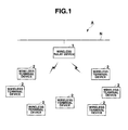
- FIG. 1 is a schematic block diagram of a wireless communication system A according to the first embodiment.
- the wireless communication system A comprises a wireless relay device 1 connected to other wireless relay devices or external devices by way of a communication network N and wireless terminal devices 2 wirelessly connected to the wireless relay device 1.
- one of wireless channels that divide a predetermined frequency range is selected to perform wireless communications between the wireless relay device 1 and the wireless terminal device 2. For instance, a frequency range of 2.4 GHz is divided into 16 channels so as not to overlap each other, channel 11 to channel 26, and wireless communications are conducted between the wireless relay device 1 and the wireless terminal device 2 by use of one of the channels 11 to 26.
- wireless relay device 1 or an external device and the wireless terminal device 2 are collectively referred to as wireless communication devices.
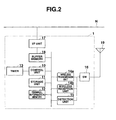
- FIG. 2 is a schematic diagram of the structure of the wireless relay device 1.
- the wireless relay device 1 comprises a control unit 10, a storage unit 11, a terminal information memory 12, a timer 13, a wireless transmission unit 14a, a wireless reception unit 14b, a detection unit 15, a switch unit (SW) 16, an interface (I/F) unit 17, a buffer memory 18, an antenna 19, and the like, which are electrically connected to one another.
- a control unit 10 a storage unit 11, a terminal information memory 12, a timer 13, a wireless transmission unit 14a, a wireless reception unit 14b, a detection unit 15, a switch unit (SW) 16, an interface (I/F) unit 17, a buffer memory 18, an antenna 19, and the like, which are electrically connected to one another.
- SW switch unit
- I/F interface
- the control unit 10 comprises a central processing unit (CPU), a read only memory (ROM), a random access memory (RAM), and the like.
- the control unit 10 reads designated programs, tables and data from various programs and various kinds of tables and data stored in the storage unit 11 and the terminal information memory 12.
- the control unit 10 expands the read-out programs, tables and data onto the RAM or the work area of the storage unit 11 or the terminal information memory 12, and executes various kinds of processing in cooperation with the programs.
- the control unit 10 stores the processing results into the RAM or a specific area of the storage unit 11 or the terminal information memory 12, and issues instructions to the units of the wireless relay device 1 to control the entire operation of the wireless relay device 1.
- the control unit 10 performs a verification process (channel scanning process) for communication conditions of wireless channels to select and determine a wireless channel of the best radio wave condition with the lowest interference level in the wireless frequency band that is divided in advance into different wireless channels, as a wireless channel (in-use channel) that is used for wireless communications with the wireless terminal device 2.
- a verification process channel scanning process
- the detection unit 15 when detecting the field intensities of selectable wireless channels (i.e., when executing energy scanning), the detection unit 15 detects the field intensities of wireless channels (detection target channels) that are predetermined from among the selectable wireless channels. Then, based on the field intensities of the detection target channels, an estimation process is executed to calculate estimation values of the field intensities of wireless channels (undetected channels) for which the field intensities are not yet detected.
- the detection target channels in the estimation process according to the first embodiment are channels 11, 14, 17, 20, 23 and 26 out of 16 channels, channels 11 to 26, estimation values of the field intensities are calculated for the undetected channels, i.e., channels 12, 13, 15, 16, 18, 19, 21, 22, 24 and 25. It is assumed here that a channel with a smaller number uses a lower frequency.
- the estimation process of the present embodiment includes the first to third estimation processes, and one of the processes is selected and set in advance.
- the mean value of the field intensities of two detection target channels above and below an undetected channel is calculated for each undetected channel.
- the calculated mean value is adopted for the estimation value of the field intensity of the undetected channel.
- the higher one of the field intensities of two detection target channels above and below an undetected channel is adopted for the estimation value of the field intensity of the undetected channel.
- the estimation value of the field intensity of an undetected channel is calculated for each undetected channel in such a manner that a ratio of "the number of wireless channel intervals between two adjacent detection target channels above and below the undetected channel” to "the number of wireless channel intervals between the undetected channel and a detection target channel in an adjacent frequency band that is below the undetected channel” is equal to a ratio of "the difference between the field intensities of the two adjacent detection target channels above and below the undetected channel” to "the difference between the field intensity of the undetected channel and the field intensity of the detection target channel in the adjacent frequency range which is below the undetected channel".
- the storage unit 11 is formed of a non-volatile memory such as a magnetic recording medium and an optical recording medium and a semiconductor in which data can be electrically erased and rewritten, and the storage unit 11 is fixed to or detachably arranged in the wireless relay device 1.
- the storage unit 11 stores in advance various programs to be executed by the control unit 10 and various tables, data, field intensity tables and the like that are to be used in these programs.
- the field intensity table stores the field intensities of the wireless channels that are detected or estimated.
- the terminal information memory 12 is formed of a memory in which data can be electrically erased and rewritten.
- the terminal information memory 12 stores terminal information such as node addresses representing information specific to each of the wireless terminal devices 2 that are connected to the wireless relay device 1.
- the timer 13 measures intervals (scan intervals) of timings of verifying the communication conditions of the wireless channels and outputs a detection timing signal to the control unit 10 at each scan interval.
- the wireless transmission unit 14a comprises a modulation circuit, a radio frequency (RF) circuit and the like.
- the unit 14a adjusts packet transmission power. It also creates a packet by encoding transmission data in accordance with an instruction from the control unit 10, modulates the created packet, and transmits the packet to the wireless terminal device 2 by way of the antenna 19.
- RF radio frequency
- the wireless reception unit 14b comprises a demodulation circuit, an RF circuit and the like.
- the unit 14b adjusts the packet reception sensitivity, and it also demodulates the packet received by way of the antenna 19 and outputs to the control unit 10 the data that is obtained by analyzing the demodulated packet.
- a communication unit is realized by the wireless transmission unit 14a, the wireless reception unit 14b and the antenna 19 to perform wireless communications with the wireless terminal device 2, which is a wireless communication device, by use of one of multiple wireless channels.
- the detection unit 15 detects the power, noise power, interference power and the like of the wireless channels (channels 11 to 26) used for wireless communications by way of the antenna 19 and detects the field intensity of each wireless channel at regular intervals.
- the wireless reception unit 14b may be configured to have the power detection function of the detection unit 15.
- the SW 16 is arranged between the antenna 19 and the section of the wireless transmission unit 14a, the wireless reception unit 14b and the detection unit 15 so that switching can be performed among the units connected to the antenna 19 (the wireless transmission unit 14a, the wireless reception unit 14b and the detection unit 15) in accordance with an instruction issued by the control unit 10.
- the I/F unit 17 controls communications that are performed with another wireless relay device 1 or an external device connected by way of the communication network N, by a certain communication method.
- the buffer memory 18 temporarily stores the data received by way of the wired I/F 17.
- the wireless terminal device 2 comprises a control unit, a storage unit, a timer, a wireless reception unit, a detection unit, a switching unit (SW), an antenna and the like, which are electrically connected to one another.
- the wireless terminal device 2 performs wireless communications with the wireless relay device 1 by way of one of the wireless channels.
- the wireless terminal device 2 executes a channel scanning process in the same manner as the wireless relay device 1 when, for example, the communication condition of the in-use channel deteriorates and a different wireless channel needs to be found to perform wireless communications with the wireless relay device 1.
- the channel scanning process executed by the wireless terminal device 2 is the same as the channel scanning process executed by the wireless relay device 1, and thus illustration and explanation thereof is omitted. Because the wireless terminal device 2 executes the same channel scanning process as the wireless relay device 1 does, both the wireless relay device 1 and the wireless terminal device 2 are realized as wireless communication devices.
- FIG. 3 is the main flowchart of the channel scanning process according to the present embodiment executed by the wireless relay device 1. The process indicated in FIG. 3 is executed in cooperation between the control unit 10 and other units of the wireless relay device 1 when the power is being supplied to the wireless relay device 1.
- the control unit 10 determines whether or not a detection timing signal is input from the timer 13 (step S1). When the detection timing signal is input (YES in step S1), the control unit 10 executes a detection process (energy scanning) (step S2), and executes an estimation process on undetected channels (step S3). One of the first to third estimation processes is selected in advance as an estimation process to be executed in step S3.
- the control unit 10 writes the field intensities of the wireless channels detected in step S2 or estimated in step S3 into the field intensity table so that the field intensity table is updated (step S4), and the process returns to step S1.
- step S1 When no detection timing signal is input (NO in step S1), the control unit 10 determines whether or not there is any data that is to be received by the wireless reception unit 14b by way of the antenna 19 (step S5). When there is no such data (NO in step S5), the control unit 10 proceeds to step S7. When there is data to be received (YES in step S5), the control unit 10 executes a reception process for this data (step S6).
- step S7 determines whether or not there is any data that is to be transmitted from the wireless transmission unit 14a (step S7). When there is no such data (NO in step S7), the control unit 10 proceeds to step S9. When there is data to be transmitted (YES in step S7), the control unit 10 executes a transmission process for this data (step S8).
- step S8 or step S7 the control unit 10 reads the field intensity table from the storage unit 11 (step S9), and determines whether or not the communication condition of the wireless channel (in-use channel) currently being used by the wireless transmission unit 14a and the wireless reception unit 14b to perform wireless communications with the wireless terminal device 2 deteriorates (step S10).
- step S10 whether or not the field intensity of the in-use channel is greater than a predetermined threshold value is judged by referring to the field intensity table.
- the field intensity of the in-use channel is greater than the threshold value, it is determined that the communication condition deteriorates.
- control unit 10 changes the in-use channel to a wireless channel in the best communication condition (i.e., the one having the smallest field intensity) by referring to the field intensity table (step S11), and returns to step S1.
- step S10 When the communication condition of the in-use channel does not deteriorate (NO in step S10), the control unit 10 executes a communication quality evaluation process (step S12).
- step S12 whether or not the communication quality of the in-use channel deteriorates is evaluated by judging, for example, whether the ACK reception rate or the packet error incidence rate regarding the data transmitted in the in-use channel is larger than or equal to a predetermined percentage.
- step S12 the control unit 10 determines whether or not the communication quality of the in-use channel deteriorates (step S13). When the communication quality of the in-use channel deteriorates (YES in step S13), the control unit 10 proceeds to step S11. When the communication quality of the in-use channel does not deteriorate (NO in step S13), the control unit 10 returns to step S1.
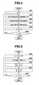
- FIG. 4 is a flowchart of the detection process according to the present embodiment executed in step S2.
- the detection process indicated in FIG. 4 it is assumed that every three channels are selected, starting with channel 11 (i.e., channels 11, 14, 17, 20, 23 and 26) and the selected six wireless channels are determined as detection target channels.
- control unit 10 sets a variable x to 11 (step S11). Then, the control unit 10 sets the wireless channel for which the field intensity is to be detected (detection target channel) to the wireless channel having a number indicted by the variable x (step S22).
- the control unit 10 causes the detection unit 15 to detect (scan) the field intensity of the detection target channel (step S23), and determines the detection value detected by the detection unit 15 as the field intensity C[x] of the detection target channel (step S24).
- the control unit 10 adds 3 to the variable x to set a new variable x (step S25), and determines whether or not the variable x is greater than the maximum number of the configurable wireless channels (26 in this example) (step S26).
- step S26 When the variable x is smaller than or equal to 26 (NO in step S26), the control unit 10 returns to step S22. When the variable x is greater than 26 (YES in step S26), the control unit 10 terminates the process.
- step S3 the first to third estimation processes executed in step S3 will be explained with reference to the flowcharts of FIGS. 5 to 7 .
- step S3 one of the processes indicated in FIGS. 5 to 7 is executed.
- every three channels are selected, starting with channel 11 (i.e., channels 11, 14, 17, 20, 23 and 26), and the detection target channels are set to these selected wireless channels.
- FIG. 5 is a flowchart of the first estimation process.
- control unit 10 sets the variable a to 11, and the variable b to 14, which is obtained by adding 3 to the variable a (step S31).
- the variables a and b represent the numbers of the detection target channels that are to be referred to.
- the control unit 10 calculates an average value D of the field intensity C[a] of a wireless channel having the number indicated by the variable a and the field intensity C[b] of a wireless channel having the number indicated by the variable b, in accordance with the following equation (1) (step S32).
- D a + C b / 2
- the control unit 10 determines the average value D calculated in step S32 as the field intensity C[a+1] of the wireless channel having the number obtained by adding 1 to the variable a , and also as the field intensity C[a+2] of the wireless channel having the number obtained by adding 2 to the variable a (step S33).
- the control unit 10 sets a new variable a by adding 3 to the variable a , and sets a new variable b by adding 3 to the variable b (step S34).
- the control unit 10 determines whether the variable a is greater than the maximum number of the settable wireless channels (26 in this example) (step S35).
- control unit 10 returns to step S32 when the variable a is smaller than or equal to 26 (NO in step S35), and the control unit 10 terminates the process when the variable a is greater than 26 (YES in step S35).
- FIG. 8A shows an example field intensity table created when the first estimation process is set in step S3.
- the shaded channel numbers (11, 14, 17, 20, 23 and 26) and field intensities of the wireless channels are the detection target channels and the field intensities detected in step S2.
- non-shaded channel numbers (12, 13, 15, 16, 18, 19, 21, 22, 24 and 25) and field intensities of the wireless channels are undetected channels and field intensities estimated in the first estimation process.
- the field intensity of an undetected channel is the mean value of the field intensities of two detection target channels above and below this channel.
- the mean value 66 of the field intensity 53 of channel 11 and the field intensity 78 of channel 14 serves as the estimated value of the field intensity of each of channels 12 and 13.
- the mean value of the field intensities of two detection target channels above and below an undetected channel is employed as the estimated value of the field intensity of the undetected channel.
- FIG. 6 is a flowchart of the second estimation process.
- control unit 10 sets the variable a to 11, and the variable b to 14, which is obtained by adding 3 to the variable a (step S41).
- the variables a and b represent the numbers of the detection target channels that are to be referred to.
- the control unit 10 determines whether or not the field intensity C[a] of the wireless channel of the number indicated by the variable a is greater than the field intensity C[b] of the wireless channel of the number indicated by the variable b (step S42).
- control unit 10 determines the field intensity C[a] of the wireless channel of the number indicated by the variable a as a selected field intensity E (step S43).
- control unit 10 determines the field intensity C[b] of the wireless channel of the number indicated by the variable b as the selected field intensity E (step S44).
- the control unit 10 determines that the field intensity C[a+1] of the wireless channel of the number indicated by a value obtained by adding 1 to the variable a and the field intensity C[a+2] of the wireless channel of the number indicated by a value obtained by adding 2 to the variable a are the selected field intensity E set in step S43 or S44 (step S45).
- the control unit 10 adds 3 to the variable a to set a new variable a, and 3 to the variable b to set a new variable b (step S46).
- the control unit 10 determines whether or not the variable a is greater than the maximum number of the configurable wireless channels (26 in this example) (step S47).
- step S47 When the variable a is smaller than or equal to 26 (NO in step S47), the control unit 10 returns to step S42, and when the variable a is greater than 26 (YES in step S47), the process is terminated.
- FIG. 8B shows an example field intensity table established when the second estimation process is set in step S3.
- the shaded channel numbers (11, 14, 17, 20, 23 and 26) and field intensities of wireless channels are the detection target channels and the field intensities detected in step S2.
- the non-shaded channel numbers (12, 13, 15, 16, 18, 19, 21, 22, 24 and 25) and field intensities of wireless channels are undetected channels and field intensities estimated in the second estimation process.
- the field intensity of an undetected channel is a higher one of the field intensities of the two detection target channels above and below the undetected channel.
- the undetected channels are channels 12 and 13 and the two detection target channels above and below channels 12 and 13 are channels 11 and 14, the higher one of the field intensity 53 of channel 11 and the field intensity 78 of the channel 14, which is the field intensity 78, becomes the estimated value for the channels 12 and 13.
- the higher one of the field intensities of the two detection target channels above and below the undetected channel is employed as the estimated value of the field intensity of an undetected channel.
- the field intensities (C[a+1] and C[a+2]) of the two undetected channels between two detection target channels are determined either as the average value D of the field intensities of the two detection target channels (i.e., the wireless channels indicated by the variables a and b) above and below the undetected channels or as the greater one of the field intensities (selected field intensity E) of the two detection target channels.
- FIG. 7 is a flowchart of the third estimation process.
- control unit 10 sets the variable a to 11, and the variable b to 14, which is obtained by adding 3 to the variable a (step S51).
- the variables a and b represent the number of detection target channels that are used for reference.
- the control unit 10 calculates the field intensity C[a+1] of the wireless channel of the number indicated by a value obtained by adding 1 to the variable a and the field intensity C[a+2] of the wireless channel of the number indicated by a value obtained by adding 2 to the variable a (step S52).
- C ⁇ a + 1 C a + ( C b - C a ) / 3
- C ⁇ a + 2 C a + 2 ( C b - C a ) / 3
- the wireless channels of the numbers indicated by the variables a and b) above and below the undetected wireless channel becomes equal to the ratio (C[a+1]-C[a]):(C[b]-C[a]) of "the difference C[a+1]-C[a] between the field intensity C[a+1] of the undetected wireless channel and the field intensity C[a] of the detection target channel below the undetected wireless channel” to "the difference C[b] - C[a] between the field intensities of the two detection target channels above and below the undetected wireless channel".
- the control unit 10 adds 3 to the variable a to set up a new variable a , and 3 to the variable b to set up a new variable b (step S53), and determines whether or not the variable a is greater than the maximum number of the configurable wireless channels (26 in this example) (step S54).
- step S54 When the variable a is smaller than or equal to 26 (NO in step S54), the control unit 10 returns to step S52, and when the variable a is greater than 26 (YES in step S54), the control unit 10 terminates the process.
- FIG. 8C shows an example field intensity table established when the third estimation process is set in step S3.
- the shaded channel numbers (11, 14, 17, 20, 23 and 26) and field intensities of wireless channels are the detection target channels and the field intensities detected in step S2.
- the non-shaded channel numbers (12, 13, 15, 16, 18, 19, 21, 22, 24 and 25) and field intensities of wireless channels are undetected channels and the field intensities estimated in the third estimation process.
- the field intensity of an undetected channel is based on the ratio of the numbers of wireless channel intervals and the ratio of the field intensity differences.
- the ratio of wireless channel intervals is 1 to 3.
- the calculated value (61) is the estimated value for the field intensity of channel 12.
- the estimated value is calculated in a similar manner for the undetected channel 13 that is adjacent to channel 12, which results in 70.
- the estimated value of the field intensity of an undetected channel can be obtained in the third estimation process by making the ratio of wireless channel intervals equal to the ratio of differences of the field intensities of wireless channels.
- the detection unit when verifying the communication conditions of multiple wireless channels, the detection unit detects the field intensities of detection target channels predetermined from among the wireless channels, and the estimated values of the field intensities of the remaining undetected channels are calculated, based on the field intensities of the detection target channels for which the field intensity detection has been performed by the detection unit.
- time and power required for the field intensity detection can be reduced when verifying the communication conditions of the wireless channels, and therefore time and power required for the wireless channel selection process can be reduced.
- the general structure of the wireless communication system according to the second embodiment is the same as that of the wireless communication system according to the first embodiment illustrated in FIG. 1 , and thus the illustration and explanation thereof is omitted.
- the general structure of the wireless relay device 1 according to the second embodiment is the same as the first embodiment, and thus the illustration is omitted and the explanation focuses on the differences only. That is, a wireless terminal device 2 executes a channel scanning process similar to the one executed by the wireless relay device 1, and wireless communication devices include the wireless relay devices 1 and the wireless terminal device 2.
- the control unit 10 performs a channel scanning process to select a wireless channel having the least interference and the best radio wave condition from the wireless frequency range that is divided in advance into multiple wireless channels, as a wireless channel (in-use channel) that is to be used during wireless communications with the wireless terminal device 2.
- the detection unit 15 when detecting the field intensities of selectable wireless channels (i.e., when executing energy scanning), the detection unit 15 detects the field intensities of several wireless channels (detection target channels) predetermined from the multiple wireless channels. When the first energy scanning is finished, the detection target channels are shifted in the frequency direction.
- an estimation process is executed to calculate the estimated values of the field intensities of undetected channels for which the field intensity detection is not performed, based on the field intensities detected by the scanning operation and also the field intensities detected by a scanning operation prior to the current scanning operation.
- detection target channels are shifted in the frequency direction at every scanning. For example, among 16 channels, i.e., channels 11 to 26, the field intensity detection is performed on six channels 11, 14, 17, 20, 23 and 26 as detection target channels in the first scanning, and then the field intensity detection is performed on five channels 12, 15, 18, 21 and 24 as detection target channels at in the second scanning.
- the estimated value of the field intensity of channel 11 is calculated in the second and third scanning, based on the detected field intensity of channel 11 of the first and fourth scanning.
- the estimation process according to the second embodiment includes the following fourth to sixth estimation processes, one of which is selected and set in advance.
- the estimated value of the field intensity of a channel that is not detected in a scanning operation is determined from the mean value of two field intensities detected in two scanning operations prior to and subsequent to the scanning operation of interest, in which the field intensity detection is performed on the channel.
- the estimated value of the field intensity of a channel that is not detected at a scanning operation is a greater one of the field intensity detected in the scanning operation executed prior to the scanning operation of interest in which the field intensity detection is performed on the channel and the field intensity detected in the scanning operation executed subsequent to the scanning operation of interest in which the field intensity detection is performed on the channel.
- the estimated value of the field intensity of a channel that is not detected in a scanning operation is calculated in such a manner that the ratio of "a difference in the number of scanning operations between the scanning operation of interest and the scanning operation for detecting the channel of interest" to "a difference in the number of scanning operations between two scanning operations for detecting the channel of interest" is equal to the ratio of "the difference between the estimated value and the field intensity detected in the previous scanning” to "the difference between the field intensity detected in the scanning operation prior to the scanning operation in which the estimation is made and the field intensity detected in the scanning operation subsequent to the scanning operation in which the estimation is made".
- the wireless terminal device 2 of the second embodiment has the same structure as that of the first embodiment, and executes the same channel scanning process as the one executed by the wireless relay device 1 of the second embodiment.
- the structure and channel scanning process of the wireless terminal device 2 is therefore omitted from the explanation.
- FIG. 9 is the main flowchart of the channel scanning process executed by the wireless relay device 1 according to the second embodiment. The process indicated in FIG. 9 is executed in coordination between the control unit 10 and other units of the wireless relay device 1 when the power is being supplied to the wireless relay device 1.
- control unit 10 sets a counter value n of a counter that counts the number of scanning operations, to 0 (step S61).
- the control unit 10 determines whether or not a detection timing signal is input from the timer 13 (step S62). When the detection timing signal is input (YES in step S62), the control unit 10 executes a detection process (energy scanning) (step S63), and executes an estimation process (step S64). As the estimation process executed in step S64, one of the fourth to sixth estimation processes is preset.
- the control unit 10 writes the field intensities of the wireless channels detected in step S63 or estimated in step S64 into the field intensity table and thereby updates the field intensity table (step S65), and determines whether or not the counter value n representing the number of scanning operations is 255 (step S66).
- step S66 8-bit control is conducted and thus the maximum counter value is set to 254, but the maximum counter value may be any number larger than or equal to the number of wireless channels.
- step S66 When the counter value n representing the number of scanning operations is 255 (YES in step S66), the control unit 10 returns to step S61. When the counter value n representing the number of scanning operations is not 255 (NO in step S66), the control unit 10 increments the counter value n representing the number of scanning operations by 1 to set a new counter value (step S67), and returns to step S62.
- step S68 When a detection timing signal is not input (NO in step S62), the control unit 10 proceeds to step S68.
- the process of steps S68 to S76 is substantially the same as the process of steps S5 to S13 of the first embodiment, except that, when reading the field intensity table from the storage unit 11 in step S72, data (field intensity records) regarding the latest scanning operation (counter value n-3) containing the field intensities of all the wireless channels is read. The explanation is therefore omitted.
- FIG. 10 is a flowchart of the detection process executed in step S63 according to the second embodiment.
- the initial detection target channels are set to every four wireless channels (e.g., channels 11, 15, 19 and 23).
- control unit 10 divides the counter value n representing the number of scanning operations by 4 and adds the remainder to 11, and sets the obtained value (11 + n mod 4) as the variable x (step S81).
- the process of steps S82 to S84 is the same as that of steps S22 to S24 of the first embodiment, and thus the explanation is omitted.
- the control unit 10 adds 4 to the variable x to set a new variable x (step S85), and determines whether or not the variable x is greater than the maximum number of the settable wireless channels (26 in this example) (step S86).
- step S86 When the variable x is smaller than or equal to 26 (NO in step S86), the control unit 10 returns to step S82. When the variable x is greater than 26 (YES in step S86), the control unit 10 terminates the process.
- step S64 the fourth to sixth estimation processes executed in step S64 are explained with reference to the flowcharts of FIGS. 11 to 13 .
- One of the processes indicated in FIGS. 11 to 13 is executed in step S64. Because the detection target channels are every four wireless channels in FIGS. 11 to 13 , once the field intensity of a detection target channel is detected at a certain scanning operation, it is not detected for the next three scanning operations.
- FIG. 11 is a flowchart of the fourth estimation process.
- control unit 10 divides the counter value n representing the number of scanning operations by 4 and sets the remainder (n mod 4) to the variable a, while it adds 11 to the variable a and sets the value to the variable b (step S91).
- the variable b indicates the number of the detection target channel that is referred to in the n-th scanning operation.
- the control unit 10 calculates an mean value F of the field intensity C[n-4,b] of the wireless channel of the number indicated by the variable b detected in the (n-4)th scanning operation and the field intensity C[n,c] of the wireless channel of the number indicated by the variable b detected in the n-th scanning operation (step S92).
- F C ⁇ n - 4 , b + C n ⁇ b / 2
- the control unit 10 determines the mean value F calculated in step S92, as the field intensities C[n-1,b], C[n-2,b], and C[n-3,b] of the wireless channel of the number indicated by the variable b in the (n-1)th, (n-2)th and (n-3)th scanning operations, respectively, in which the field intensity detection is not performed on this channel, prior to the n-th scanning operation (step S93).
- the control unit 10 adds 4 to the variable b to set a new variable b (step S94), and determines whether or not the variable b is greater than the maximum number of the configurable wireless channels (26 in this example) (step S95).
- step S95 When the variable b is smaller than or equal to 26 (NO in step S95), the control unit 10 returns to step S92, while, when the variable b is greater than 26 (YES in step S95), the control unit 10 terminates the process.
- FIG. 14 is an example field intensity table established when the fourth estimation process is set in step S64.
- FIG. 14 shows an example of the field intensity table when the counter value n representing the number of scanning operations is 11.
- the shaded field intensities are detected in step S63, and the non-shaded field intensities are estimated by the fourth estimation process.
- the estimated value of the field intensity is not calculated and is indicated by "-" in FIG. 14 .
- the field intensity (estimated value) of any wireless channel in the non-detected scanning is the mean value of the detected field intensities obtained in the preceding and following scanning operations.
- the mean value, 66, of the detected field intensity 70 of the channel 11 in the 0th scanning operation and the detected field intensity 61 of the channel 11 in the fourth scanning operation becomes the estimated value of the field intensity of the channel 11 for the first, second and third scanning operations.
- the estimated value of the field intensity of a channel that is not detected in a certain scanning operation is the mean value of two field intensities detected in two scanning operations in which the field intensity detection is performed on this channel.
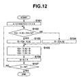
- FIG. 12 is a flowchart of the fifth estimation process.
- control unit 10 divides the counter value n representing the number of scanning operations by 4 and sets the remainder (n mod 4) to the variable a, and adds 11 to the variable a and sets the obtained value to the variable b (step S101).
- the variable b represents the number of the detection target channel that is referred to in the n-th scanning operation.
- the control unit 10 determines whether or not the field intensity C[n-4,b] of the wireless channel of the number indicated by the variable b in the (n-4)th scanning operation is greater than the field intensity C[n,b] of the wireless channel of the number indicated by the variable b in the n-th scanning operation (step S102).
- the control unit 10 determines the field intensity C[n-4,b] of the wireless channel of the number indicated by the variable b that is detected in the (n-4)th scanning operation, as a selected field intensity G (step S103).
- the control unit 10 determines the field intensity C[n,b] of the wireless channel of the number indicated by the variable b that is detected in the n-th scanning operation, as the selected field intensity G (step S104).
- the control unit 10 determines the selected field intensity G set in step S102 or S103, as the estimated field intensities C[n-1,b], C[n-2,b], and C[n-3,b] of the wireless channel of the number indicated by the variable b in the (n-1)th, (n-2)th and (n-3)th scanning operations, respectively, in which the field intensity detection is not performed on this channel, before the n-th scanning operation (step S105).
- the control unit 10 adds 4 to the variable b to set a new variable b (step S106), and determines whether or not the variable b is greater than the maximum value of the configurable wireless channels (26 in this example) (step S107).
- step S107 When the variable b is smaller than or equal to 26 (NO in step S107), the control unit 10 returns to step S102, while, when the variable b is greater than 26 (YES in step S107), the control unit 10 terminates the process.
- FIG. 15 is an example field intensity table established in which the fifth estimation process is set in step S64.
- the counter value n representing the number of scanning operations is set to 11.
- the shaded field intensities are the intensities detected in step S63, and the non-shaded field intensities are the intensities estimated in the fifth estimation process.
- the estimated value of the field intensity is not calculated and is indicated as "-" in FIG. 15 .
- the field intensity (estimated value) of each wireless channel in an undetected scanning operation is a higher one of the detection values of the field intensities obtained in the preceding and subsequent scanning operations.
- the estimated value of the field intensity of an undetected channel at a certain scanning operation in the fifth estimation process a higher one of the field intensity of the channel detected at a scanning operation executed prior to this scanning operation and the field intensity of the channel detected at a scanning operation executed subsequent to the scanning operation is employed.
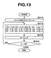
- FIG. 13 is a flowchart of the sixth estimation process.
- control unit 10 divides the counter value n representing the number of scanning operations by 4 and sets the remainder (n mod 4) to the variable a, and adds 11 to the variable a and sets the obtained value to the variable b (step S101).
- the variable b represents the number of a detection target channel that is referred to in the n-th scanning operation.
- the control unit 10 calculates the field intensities C[n-1,b], C[n-2,b] and C[n-3,b] for the wireless channel of the number indicated by the variable b in the (n-1)th, (n-2)th and (n-3)th scanning operations, respectively, in which the field intensity detection is not performed on this channel, prior to the n-th scanning operation (step S112).
- the control unit 10 adds 4 to the variable b to set a new variable b (step S113), and determines whether or not the variable b is greater than the maximum number of the configurable wireless channels (26 in this example) (step S114).
- step S114 When the variable b is smaller than or equal to 26 (NO in step S114), the control unit 10 returns to step S112, while, when the variable b is greater than 26 (YES in step S114), the control unit 10 terminates the process.
- FIG. 16 shows an example field intensity table established in step S64 when the sixth estimation process is set.
- the counter value n representing the number of scanning operations is 11.
- the shaded field intensities are the intensities detected in step S63 for the n-th scanning operation, while the non-shaded field intensities are the ones estimated in the sixth estimation process.
- the estimated value of the field intensity is not calculated and is indicated by "-" in FIG. 16 .
- the field intensity (estimated value) of a wireless channel in an undetected scanning operation is based on the ratio of the numbers of scanning operations prior to and subsequent to a certain scanning operation where the field intensity detection is performed on the channel and the ratio of differences in the detection values of the field intensities.
- the difference between the first scanning operation and the 0th scanning is 1 operation, while the difference between the 4th scanning and the 0th scanning is 4 operations.
- the ratio of the number of scanning operations at the time of the first scanning operation to the number of scanning operations between the preceding and following scanning operations in which detection is performed on channel 11 is 1:4.
- the estimated value of the field intensity of a channel that is not detected in a scanning operation is obtained by performing linear interpolation from the two field intensities detected in the two scanning operations in which the field intensity detection is performed on the channel, prior to and subsequent to the undetected scanning operation.
- the second embodiment when verifying the communication conditions of multiple wireless channels, several detection target channels selected from the wireless channels are shifted in the frequency direction every time of energy scanning, and the field intensity detection is performed onto these detection target channels only, by the detection unit.
- the estimated values of the field intensities of the remaining undetected channels can be calculated.
- the field intensity detection does not have to deal with all the wireless channels in one scanning operation. This reduces the time and power required for the field intensity detection when verifying the communication conditions of multiple wireless channels, and thereby reduces the time and power required for the wireless channel selection process.
- the time and power required for the field intensity detection can be reduced when verifying the communication conditions of multiple wireless channels, and the time and power required for the wireless channel selection process can be reduced.
Landscapes
- Engineering & Computer Science (AREA)
- Quality & Reliability (AREA)
- Computer Networks & Wireless Communication (AREA)
- Signal Processing (AREA)
- Physics & Mathematics (AREA)
- Electromagnetism (AREA)
- Mobile Radio Communication Systems (AREA)
Abstract
Description
- The present invention relates generally to a wireless communication device and a wireless communication method for detecting the field intensities of wireless channels.
- In a recent wireless communication system such as the one defined by IEEE 802.15.4, a predetermined range of radio frequency is divided into wireless channels in such a manner as not to overlap one another in a certain bandwidth. Wireless communications are established between wireless communication devices through a selected one of the divided wireless channels.
- In order to select a wireless channel, the wireless communication device verifies communication conditions of all the selectable wireless channels. In the verification process for the communication conditions, field intensity detection (energy scanning) is performed on all the wireless channels. The wireless communication device calculates the interference wave levels and the like of the selectable wireless channels in accordance with the results of detecting the field intensities of the channels, and selects a wireless channel that has a good communication condition.
- According to Jpn. Pat. Appln. KOKAI Publication No.
2007-311851 - In addition, another problem resides in the technology in which the field intensity detection is performed on all the wireless channels at certain scan intervals; it consumes a large amount of electricity on a regular basis.
- An object of the invention is to reduce the period of time and consumption of power required for the field intensity detection that is executed when verifying the communication conditions of selectable wireless channels, and thereby to reduce the period of time and consumption of power required for the wireless channel selection process.
- According to an embodiment of the present invention, a wireless communication device includes a communication unit configured to communicate with another wireless communication device by use of a wireless channel selected from wireless channels; a detection unit configured to detect field intensities of first wireless channels; and a control unit configured to calculate a field intensity of a second wireless channel based on the field intensities of the first wireless channels, wherein the first wireless channels do not include the second wireless channel.
- According to another embodiment of the present invention, a wireless communication method includes detecting field intensities of first wireless channels selected from a plurality of wireless channels when verifying communication conditions of the plurality of wireless channels; and calculating a field intensity of a second wireless channel based on the field intensities of the first wireless channels, wherein the first wireless channels do not include the second wireless channel.
- The invention can be more fully understood from the following detailed description when taken in conjunction with the accompanying drawings, in which:
-
FIG. 1 is a schematic block diagram of a wireless communication system according to the first embodiment. -
FIG. 2 is a schematic block diagram of a wireless relay device. -
FIG. 3 is the main flowchart of a channel scanning process according to the first embodiment. -
FIG. 4 is a flowchart of the detection process according to the first embodiment. -
FIG. 5 is a flowchart of the first estimation process. -
FIG. 6 is a flowchart of the second estimation process. -
FIG. 7 is a flowchart of the third estimation process. -
FIG. 8A is a diagram of an example field intensity table established when the first estimation process is set in step S3. -
FIG. 8B is a diagram of an example field intensity table established when the second estimation process is set in step S3. -
FIG. 8C is a diagram of an example field intensity table established when the third estimation process is set in step S3. -
FIG. 9 is the main flowchart of a channel scanning process according to the second embodiment. -
FIG. 10 is a flowchart of a detection process according to the second embodiment. -
FIG. 11 is a flowchart of the fourth estimation process. -
FIG. 12 is a flowchart of the fifth estimation process. -
FIG. 13 is a flowchart of the sixth estimation process. -
FIG. 14 is a diagram of an example field intensity table established when the fourth estimation process is set in step S64. -
FIG. 15 is a diagram of an example field intensity table established when the fifth estimation process is set in step S64. -
FIG. 16 is a diagram of an example field intensity table established when the sixth estimation process is set in step S64. - The embodiments of the present invention will be explained in detail below, with reference to the attached drawings. The present invention is not limited to these embodiments, however. The terms of the invention are not limited to the ones adopted here.
- The structure will be explained first.
-
FIG. 1 is a schematic block diagram of a wireless communication system A according to the first embodiment. - As illustrated in
FIG. 1 , the wireless communication system A comprises awireless relay device 1 connected to other wireless relay devices or external devices by way of a communication network N andwireless terminal devices 2 wirelessly connected to thewireless relay device 1. - In the wireless communication system A, one of wireless channels that divide a predetermined frequency range is selected to perform wireless communications between the
wireless relay device 1 and thewireless terminal device 2. For instance, a frequency range of 2.4 GHz is divided into 16 channels so as not to overlap each other,channel 11 tochannel 26, and wireless communications are conducted between thewireless relay device 1 and thewireless terminal device 2 by use of one of thechannels 11 to 26. - Hereinafter, the
wireless relay device 1 or an external device and thewireless terminal device 2 are collectively referred to as wireless communication devices. -
FIG. 2 is a schematic diagram of the structure of thewireless relay device 1. - As illustrated in
FIG. 2 , thewireless relay device 1 comprises acontrol unit 10, astorage unit 11, aterminal information memory 12, atimer 13, awireless transmission unit 14a, awireless reception unit 14b, adetection unit 15, a switch unit (SW) 16, an interface (I/F)unit 17, abuffer memory 18, anantenna 19, and the like, which are electrically connected to one another. - The
control unit 10 comprises a central processing unit (CPU), a read only memory (ROM), a random access memory (RAM), and the like. Thecontrol unit 10 reads designated programs, tables and data from various programs and various kinds of tables and data stored in thestorage unit 11 and theterminal information memory 12. Thecontrol unit 10 expands the read-out programs, tables and data onto the RAM or the work area of thestorage unit 11 or theterminal information memory 12, and executes various kinds of processing in cooperation with the programs. Thecontrol unit 10 stores the processing results into the RAM or a specific area of thestorage unit 11 or theterminal information memory 12, and issues instructions to the units of thewireless relay device 1 to control the entire operation of thewireless relay device 1. - The
control unit 10 performs a verification process (channel scanning process) for communication conditions of wireless channels to select and determine a wireless channel of the best radio wave condition with the lowest interference level in the wireless frequency band that is divided in advance into different wireless channels, as a wireless channel (in-use channel) that is used for wireless communications with thewireless terminal device 2. - In the channel scanning process according to the first embodiment, when detecting the field intensities of selectable wireless channels (i.e., when executing energy scanning), the
detection unit 15 detects the field intensities of wireless channels (detection target channels) that are predetermined from among the selectable wireless channels. Then, based on the field intensities of the detection target channels, an estimation process is executed to calculate estimation values of the field intensities of wireless channels (undetected channels) for which the field intensities are not yet detected. - For example, when the detection target channels in the estimation process according to the first embodiment are
channels channels 11 to 26, estimation values of the field intensities are calculated for the undetected channels, i.e.,channels - The estimation process of the present embodiment includes the first to third estimation processes, and one of the processes is selected and set in advance.
- In the first estimation process, the mean value of the field intensities of two detection target channels above and below an undetected channel is calculated for each undetected channel. The calculated mean value is adopted for the estimation value of the field intensity of the undetected channel.
- In the second estimation process, for each undetected channel, the higher one of the field intensities of two detection target channels above and below an undetected channel is adopted for the estimation value of the field intensity of the undetected channel.
- In the third estimation process, the estimation value of the field intensity of an undetected channel is calculated for each undetected channel in such a manner that a ratio of "the number of wireless channel intervals between two adjacent detection target channels above and below the undetected channel" to "the number of wireless channel intervals between the undetected channel and a detection target channel in an adjacent frequency band that is below the undetected channel" is equal to a ratio of "the difference between the field intensities of the two adjacent detection target channels above and below the undetected channel" to "the difference between the field intensity of the undetected channel and the field intensity of the detection target channel in the adjacent frequency range which is below the undetected channel".
- The
storage unit 11 is formed of a non-volatile memory such as a magnetic recording medium and an optical recording medium and a semiconductor in which data can be electrically erased and rewritten, and thestorage unit 11 is fixed to or detachably arranged in thewireless relay device 1. Thestorage unit 11 stores in advance various programs to be executed by thecontrol unit 10 and various tables, data, field intensity tables and the like that are to be used in these programs. - The field intensity table according to the present embodiment stores the field intensities of the wireless channels that are detected or estimated.
- The
terminal information memory 12 is formed of a memory in which data can be electrically erased and rewritten. Theterminal information memory 12 stores terminal information such as node addresses representing information specific to each of thewireless terminal devices 2 that are connected to thewireless relay device 1. - The
timer 13 measures intervals (scan intervals) of timings of verifying the communication conditions of the wireless channels and outputs a detection timing signal to thecontrol unit 10 at each scan interval. - The
wireless transmission unit 14a comprises a modulation circuit, a radio frequency (RF) circuit and the like. Theunit 14a adjusts packet transmission power. It also creates a packet by encoding transmission data in accordance with an instruction from thecontrol unit 10, modulates the created packet, and transmits the packet to thewireless terminal device 2 by way of theantenna 19. - The
wireless reception unit 14b comprises a demodulation circuit, an RF circuit and the like. Theunit 14b adjusts the packet reception sensitivity, and it also demodulates the packet received by way of theantenna 19 and outputs to thecontrol unit 10 the data that is obtained by analyzing the demodulated packet. - A communication unit is realized by the
wireless transmission unit 14a, thewireless reception unit 14b and theantenna 19 to perform wireless communications with thewireless terminal device 2, which is a wireless communication device, by use of one of multiple wireless channels. - The
detection unit 15 detects the power, noise power, interference power and the like of the wireless channels (channels 11 to 26) used for wireless communications by way of theantenna 19 and detects the field intensity of each wireless channel at regular intervals. Thewireless reception unit 14b may be configured to have the power detection function of thedetection unit 15. - The
SW 16 is arranged between theantenna 19 and the section of thewireless transmission unit 14a, thewireless reception unit 14b and thedetection unit 15 so that switching can be performed among the units connected to the antenna 19 (thewireless transmission unit 14a, thewireless reception unit 14b and the detection unit 15) in accordance with an instruction issued by thecontrol unit 10. - The I/
F unit 17 controls communications that are performed with anotherwireless relay device 1 or an external device connected by way of the communication network N, by a certain communication method. - The
buffer memory 18 temporarily stores the data received by way of the wired I/F 17. - The
wireless terminal device 2 comprises a control unit, a storage unit, a timer, a wireless reception unit, a detection unit, a switching unit (SW), an antenna and the like, which are electrically connected to one another. Thewireless terminal device 2 performs wireless communications with thewireless relay device 1 by way of one of the wireless channels. - The
wireless terminal device 2 according to the present embodiment executes a channel scanning process in the same manner as thewireless relay device 1 when, for example, the communication condition of the in-use channel deteriorates and a different wireless channel needs to be found to perform wireless communications with thewireless relay device 1. - The channel scanning process executed by the
wireless terminal device 2 is the same as the channel scanning process executed by thewireless relay device 1, and thus illustration and explanation thereof is omitted. Because thewireless terminal device 2 executes the same channel scanning process as thewireless relay device 1 does, both thewireless relay device 1 and thewireless terminal device 2 are realized as wireless communication devices. - Next, the operation of the present embodiment will be explained.
-
FIG. 3 is the main flowchart of the channel scanning process according to the present embodiment executed by thewireless relay device 1. The process indicated inFIG. 3 is executed in cooperation between thecontrol unit 10 and other units of thewireless relay device 1 when the power is being supplied to thewireless relay device 1. - The
control unit 10 determines whether or not a detection timing signal is input from the timer 13 (step S1). When the detection timing signal is input (YES in step S1), thecontrol unit 10 executes a detection process (energy scanning) (step S2), and executes an estimation process on undetected channels (step S3). One of the first to third estimation processes is selected in advance as an estimation process to be executed in step S3. - The
control unit 10 writes the field intensities of the wireless channels detected in step S2 or estimated in step S3 into the field intensity table so that the field intensity table is updated (step S4), and the process returns to step S1. - When no detection timing signal is input (NO in step S1), the
control unit 10 determines whether or not there is any data that is to be received by thewireless reception unit 14b by way of the antenna 19 (step S5). When there is no such data (NO in step S5), thecontrol unit 10 proceeds to step S7. When there is data to be received (YES in step S5), thecontrol unit 10 executes a reception process for this data (step S6). - After step S6 or step S5 (if NO in this step), the
control unit 10 determines whether or not there is any data that is to be transmitted from thewireless transmission unit 14a (step S7). When there is no such data (NO in step S7), thecontrol unit 10 proceeds to step S9. When there is data to be transmitted (YES in step S7), thecontrol unit 10 executes a transmission process for this data (step S8). - After step S8 or step S7 (if NO in this step), the
control unit 10 reads the field intensity table from the storage unit 11 (step S9), and determines whether or not the communication condition of the wireless channel (in-use channel) currently being used by thewireless transmission unit 14a and thewireless reception unit 14b to perform wireless communications with thewireless terminal device 2 deteriorates (step S10). - In step S10, whether or not the field intensity of the in-use channel is greater than a predetermined threshold value is judged by referring to the field intensity table. When the field intensity of the in-use channel is greater than the threshold value, it is determined that the communication condition deteriorates.
- If the communication condition of the in-use channel deteriorates (YES in step S10), the
control unit 10 changes the in-use channel to a wireless channel in the best communication condition (i.e., the one having the smallest field intensity) by referring to the field intensity table (step S11), and returns to step S1. - When the communication condition of the in-use channel does not deteriorate (NO in step S10), the
control unit 10 executes a communication quality evaluation process (step S12). - In the communication quality evaluation process executed in step S12, whether or not the communication quality of the in-use channel deteriorates is evaluated by judging, for example, whether the ACK reception rate or the packet error incidence rate regarding the data transmitted in the in-use channel is larger than or equal to a predetermined percentage.
- After step S12, the
control unit 10 determines whether or not the communication quality of the in-use channel deteriorates (step S13). When the communication quality of the in-use channel deteriorates (YES in step S13), thecontrol unit 10 proceeds to step S11. When the communication quality of the in-use channel does not deteriorate (NO in step S13), thecontrol unit 10 returns to step S1. -
FIG. 4 is a flowchart of the detection process according to the present embodiment executed in step S2. In the detection process indicated inFIG. 4 , it is assumed that every three channels are selected, starting with channel 11 (i.e.,channels - First, the
control unit 10 sets a variable x to 11 (step S11). Then, thecontrol unit 10 sets the wireless channel for which the field intensity is to be detected (detection target channel) to the wireless channel having a number indicted by the variable x (step S22). - The
control unit 10 causes thedetection unit 15 to detect (scan) the field intensity of the detection target channel (step S23), and determines the detection value detected by thedetection unit 15 as the field intensity C[x] of the detection target channel (step S24). - The
control unit 10 adds 3 to the variable x to set a new variable x (step S25), and determines whether or not the variable x is greater than the maximum number of the configurable wireless channels (26 in this example) (step S26). - When the variable x is smaller than or equal to 26 (NO in step S26), the
control unit 10 returns to step S22. When the variable x is greater than 26 (YES in step S26), thecontrol unit 10 terminates the process. - Next, the first to third estimation processes executed in step S3 will be explained with reference to the flowcharts of
FIGS. 5 to 7 . In step S3, one of the processes indicated inFIGS. 5 to 7 is executed. - In the estimation processes of
FIGS. 5 to 7 , it is assumed that every three channels are selected, starting with channel 11 (i.e.,channels -
FIG. 5 is a flowchart of the first estimation process. - First, the
control unit 10 sets the variable a to 11, and the variable b to 14, which is obtained by adding 3 to the variable a (step S31). The variables a and b represent the numbers of the detection target channels that are to be referred to. - The
control unit 10 calculates an average value D of the field intensity C[a] of a wireless channel having the number indicated by the variable a and the field intensity C[b] of a wireless channel having the number indicated by the variable b, in accordance with the following equation (1) (step S32).
- The
control unit 10 determines the average value D calculated in step S32 as the field intensity C[a+1] of the wireless channel having the number obtained by adding 1 to the variable a, and also as the field intensity C[a+2] of the wireless channel having the number obtained by adding 2 to the variable a (step S33). - The
control unit 10 sets a new variable a by adding 3 to the variable a, and sets a new variable b by adding 3 to the variable b (step S34). Thecontrol unit 10 determines whether the variable a is greater than the maximum number of the settable wireless channels (26 in this example) (step S35). - The
control unit 10 returns to step S32 when the variable a is smaller than or equal to 26 (NO in step S35), and thecontrol unit 10 terminates the process when the variable a is greater than 26 (YES in step S35). -
FIG. 8A shows an example field intensity table created when the first estimation process is set in step S3. InFIG. 8A , the shaded channel numbers (11, 14, 17, 20, 23 and 26) and field intensities of the wireless channels are the detection target channels and the field intensities detected in step S2. - Furthermore, the non-shaded channel numbers (12, 13, 15, 16, 18, 19, 21, 22, 24 and 25) and field intensities of the wireless channels are undetected channels and field intensities estimated in the first estimation process.
- As illustrated in
FIG. 8A , the field intensity of an undetected channel is the mean value of the field intensities of two detection target channels above and below this channel. - For example, as illustrated in
FIG. 8A , when the undetected channels arechannels channels channels mean value 66 of thefield intensity 53 ofchannel 11 and thefield intensity 78 ofchannel 14 serves as the estimated value of the field intensity of each ofchannels - In this manner, in the first estimation process, the mean value of the field intensities of two detection target channels above and below an undetected channel is employed as the estimated value of the field intensity of the undetected channel.
-
FIG. 6 is a flowchart of the second estimation process. - First, the
control unit 10 sets the variable a to 11, and the variable b to 14, which is obtained by adding 3 to the variable a (step S41). The variables a and b represent the numbers of the detection target channels that are to be referred to. - The
control unit 10 determines whether or not the field intensity C[a] of the wireless channel of the number indicated by the variable a is greater than the field intensity C[b] of the wireless channel of the number indicated by the variable b (step S42). - When the field intensity C[a] is greater than the field intensity C[b] (YES in step S42), the
control unit 10 determines the field intensity C[a] of the wireless channel of the number indicated by the variable a as a selected field intensity E (step S43). - When the field intensity C[a] is smaller than or equal to the field intensity C[b] (NO in step S42), the
control unit 10 determines the field intensity C[b] of the wireless channel of the number indicated by the variable b as the selected field intensity E (step S44). - The
control unit 10 determines that the field intensity C[a+1] of the wireless channel of the number indicated by a value obtained by adding 1 to the variable a and the field intensity C[a+2] of the wireless channel of the number indicated by a value obtained by adding 2 to the variable a are the selected field intensity E set in step S43 or S44 (step S45). - The
control unit 10 adds 3 to the variable a to set a new variable a, and 3 to the variable b to set a new variable b (step S46). Thecontrol unit 10 determines whether or not the variable a is greater than the maximum number of the configurable wireless channels (26 in this example) (step S47). - When the variable a is smaller than or equal to 26 (NO in step S47), the
control unit 10 returns to step S42, and when the variable a is greater than 26 (YES in step S47), the process is terminated. -
FIG. 8B shows an example field intensity table established when the second estimation process is set in step S3. InFIG. 8B , the shaded channel numbers (11, 14, 17, 20, 23 and 26) and field intensities of wireless channels are the detection target channels and the field intensities detected in step S2. In addition, the non-shaded channel numbers (12, 13, 15, 16, 18, 19, 21, 22, 24 and 25) and field intensities of wireless channels are undetected channels and field intensities estimated in the second estimation process. - As illustrated in
FIG. 8B , the field intensity of an undetected channel is a higher one of the field intensities of the two detection target channels above and below the undetected channel. - For example, as illustrated in
FIG. 8B , when the undetected channels arechannels channels channels field intensity 53 ofchannel 11 and thefield intensity 78 of thechannel 14, which is thefield intensity 78, becomes the estimated value for thechannels - In this manner, in the second estimation process, the higher one of the field intensities of the two detection target channels above and below the undetected channel is employed as the estimated value of the field intensity of an undetected channel.
- According to the first embodiment, because the field intensity is detected for every three wireless channels, there are two undetected channels between any two detection target channels. For this reason, in steps S33 and S45, the field intensities (C[a+1] and C[a+2]) of the two undetected channels between two detection target channels are determined either as the average value D of the field intensities of the two detection target channels (i.e., the wireless channels indicated by the variables a and b) above and below the undetected channels or as the greater one of the field intensities (selected field intensity E) of the two detection target channels.
-
FIG. 7 is a flowchart of the third estimation process. - First, the
control unit 10 sets the variable a to 11, and the variable b to 14, which is obtained by adding 3 to the variable a (step S51). The variables a and b represent the number of detection target channels that are used for reference. - In accordance with the following equations (2) and (3), the
control unit 10 calculates the field intensity C[a+1] of the wireless channel of the number indicated by a value obtained by adding 1 to the variable a and the field intensity C[a+2] of the wireless channel of the number indicated by a value obtained by adding 2 to the variable a (step S52).

- From the equation (2), the field intensity C[a+1] of an undetected channel is calculated in such a manner that the ratio (1:3) of "the number of channel intervals (=1) between the undetected channel (i.e. the wireless channel of the number indicated by variable a+1) and the detection target channel below the undetected channel (i.e., the wireless channel of the number indicated by the variable a)" to "the number of channel intervals (=3) between the two detection target channels (i.e. the wireless channels of the numbers indicated by the variables a and b) above and below the undetected wireless channel" becomes equal to the ratio (C[a+1]-C[a]):(C[b]-C[a]) of "the difference C[a+1]-C[a] between the field intensity C[a+1] of the undetected wireless channel and the field intensity C[a] of the detection target channel below the undetected wireless channel" to "the difference C[b] - C[a] between the field intensities of the two detection target channels above and below the undetected wireless channel".
- From the equation (3), the field intensity C[a+2] of the undetected channel is calculated in such a manner that the ratio (2:3) of "the number of channel intervals (=2) between the undetected channel (i.e., the wireless channel of the number indicated by variable a+2) and the detection target channel below the undetected channel (i.e. the wireless channel of the number indicated by the variable a)" to "the number of intervals (=3) between the two detection target channels (i.e., the wireless channels of the numbers indicated by the variables a and b) above and below the undetected wireless channel" becomes equal to the ratio (C[a+2]-C[a]:C[b]-C[a]) of "the difference C[a+2] - C[a] between the field intensity C[a+2] of the undetected wireless channel and the field intensity C[a] of the detection target channel below the undetected wireless channel" to "the difference C[b] - C[a] between the field intensities of the detection target channels above and below the undetected wireless channel".
- The
control unit 10 adds 3 to the variable a to set up a new variable a, and 3 to the variable b to set up a new variable b (step S53), and determines whether or not the variable a is greater than the maximum number of the configurable wireless channels (26 in this example) (step S54). - When the variable a is smaller than or equal to 26 (NO in step S54), the
control unit 10 returns to step S52, and when the variable a is greater than 26 (YES in step S54), thecontrol unit 10 terminates the process. -
FIG. 8C shows an example field intensity table established when the third estimation process is set in step S3. InFIG. 8C , the shaded channel numbers (11, 14, 17, 20, 23 and 26) and field intensities of wireless channels are the detection target channels and the field intensities detected in step S2. Furthermore, the non-shaded channel numbers (12, 13, 15, 16, 18, 19, 21, 22, 24 and 25) and field intensities of wireless channels are undetected channels and the field intensities estimated in the third estimation process. - As illustrated in
FIG. 8C , the field intensity of an undetected channel is based on the ratio of the numbers of wireless channel intervals and the ratio of the field intensity differences. - For example, as illustrated in
FIG. 8C , when the undetected channel ischannel 12 and the two detection target channels above and belowchannel 12 arechannels channels channels channel 12 is 3. Thus, the ratio of wireless channel intervals is 1 to 3. - Further, the value of C[12] is calculated in such a manner that the ratio (ratio of field intensity differences) of the difference C[12] - C[11] between the field intensity C[12] of
channel 12 and the field intensity C[11] (=53) of thechannel 11 belowchannel 12 to the difference C[14] - C[11] between the field intensity C[11] (=53) ofchannel 11 belowchannel 12 and the field intensity C[14] (=78) ofchannel 14 abovechannel 12 becomes equal to the ratio of wireless channel intervals, 1 to 3. The calculated value (61) is the estimated value for the field intensity ofchannel 12. - The estimated value is calculated in a similar manner for the
undetected channel 13 that is adjacent to channel 12, which results in 70. - In this manner, the estimated value of the field intensity of an undetected channel can be obtained in the third estimation process by making the ratio of wireless channel intervals equal to the ratio of differences of the field intensities of wireless channels.
- As explained above, according to the present embodiment, when verifying the communication conditions of multiple wireless channels, the detection unit detects the field intensities of detection target channels predetermined from among the wireless channels, and the estimated values of the field intensities of the remaining undetected channels are calculated, based on the field intensities of the detection target channels for which the field intensity detection has been performed by the detection unit.
- Hence, because the field intensity detection does not have to be conducted on all the wireless channels, time and power required for the field intensity detection can be reduced when verifying the communication conditions of the wireless channels, and therefore time and power required for the wireless channel selection process can be reduced.
- First, the structure will be explained.
- The general structure of the wireless communication system according to the second embodiment is the same as that of the wireless communication system according to the first embodiment illustrated in
FIG. 1 , and thus the illustration and explanation thereof is omitted. - The general structure of the
wireless relay device 1 according to the second embodiment is the same as the first embodiment, and thus the illustration is omitted and the explanation focuses on the differences only. That is, awireless terminal device 2 executes a channel scanning process similar to the one executed by thewireless relay device 1, and wireless communication devices include thewireless relay devices 1 and thewireless terminal device 2. - The
control unit 10 performs a channel scanning process to select a wireless channel having the least interference and the best radio wave condition from the wireless frequency range that is divided in advance into multiple wireless channels, as a wireless channel (in-use channel) that is to be used during wireless communications with thewireless terminal device 2. - In the channel scanning process according to the second embodiment, when detecting the field intensities of selectable wireless channels (i.e., when executing energy scanning), the
detection unit 15 detects the field intensities of several wireless channels (detection target channels) predetermined from the multiple wireless channels. When the first energy scanning is finished, the detection target channels are shifted in the frequency direction. - Each time of scanning, an estimation process is executed to calculate the estimated values of the field intensities of undetected channels for which the field intensity detection is not performed, based on the field intensities detected by the scanning operation and also the field intensities detected by a scanning operation prior to the current scanning operation.
- According to the second embodiment, detection target channels are shifted in the frequency direction at every scanning. For example, among 16 channels, i.e.,
channels 11 to 26, the field intensity detection is performed on sixchannels channels - When, for example, the field intensity of the
channel 11 is detected in the first and fourth scanning, the estimated value of the field intensity ofchannel 11 is calculated in the second and third scanning, based on the detected field intensity ofchannel 11 of the first and fourth scanning. - The estimation process according to the second embodiment includes the following fourth to sixth estimation processes, one of which is selected and set in advance.
- In the fourth estimation process, the estimated value of the field intensity of a channel that is not detected in a scanning operation is determined from the mean value of two field intensities detected in two scanning operations prior to and subsequent to the scanning operation of interest, in which the field intensity detection is performed on the channel.
- In the fifth estimation process, the estimated value of the field intensity of a channel that is not detected at a scanning operation is a greater one of the field intensity detected in the scanning operation executed prior to the scanning operation of interest in which the field intensity detection is performed on the channel and the field intensity detected in the scanning operation executed subsequent to the scanning operation of interest in which the field intensity detection is performed on the channel.
- In the sixth estimation process, the estimated value of the field intensity of a channel that is not detected in a scanning operation is calculated in such a manner that the ratio of "a difference in the number of scanning operations between the scanning operation of interest and the scanning operation for detecting the channel of interest" to "a difference in the number of scanning operations between two scanning operations for detecting the channel of interest" is equal to the ratio of "the difference between the estimated value and the field intensity detected in the previous scanning" to "the difference between the field intensity detected in the scanning operation prior to the scanning operation in which the estimation is made and the field intensity detected in the scanning operation subsequent to the scanning operation in which the estimation is made".
- The
wireless terminal device 2 of the second embodiment has the same structure as that of the first embodiment, and executes the same channel scanning process as the one executed by thewireless relay device 1 of the second embodiment. The structure and channel scanning process of thewireless terminal device 2 is therefore omitted from the explanation. - Next, the operation of the second embodiment is explained.
-
FIG. 9 is the main flowchart of the channel scanning process executed by thewireless relay device 1 according to the second embodiment. The process indicated inFIG. 9 is executed in coordination between thecontrol unit 10 and other units of thewireless relay device 1 when the power is being supplied to thewireless relay device 1. - First, the
control unit 10 sets a counter value n of a counter that counts the number of scanning operations, to 0 (step S61). - The
control unit 10 determines whether or not a detection timing signal is input from the timer 13 (step S62). When the detection timing signal is input (YES in step S62), thecontrol unit 10 executes a detection process (energy scanning) (step S63), and executes an estimation process (step S64). As the estimation process executed in step S64, one of the fourth to sixth estimation processes is preset. - The
control unit 10 writes the field intensities of the wireless channels detected in step S63 or estimated in step S64 into the field intensity table and thereby updates the field intensity table (step S65), and determines whether or not the counter value n representing the number of scanning operations is 255 (step S66). - It is assumed in step S66 that 8-bit control is conducted and thus the maximum counter value is set to 254, but the maximum counter value may be any number larger than or equal to the number of wireless channels.
- When the counter value n representing the number of scanning operations is 255 (YES in step S66), the
control unit 10 returns to step S61. When the counter value n representing the number of scanning operations is not 255 (NO in step S66), thecontrol unit 10 increments the counter value n representing the number of scanning operations by 1 to set a new counter value (step S67), and returns to step S62. - When a detection timing signal is not input (NO in step S62), the
control unit 10 proceeds to step S68. The process of steps S68 to S76 is substantially the same as the process of steps S5 to S13 of the first embodiment, except that, when reading the field intensity table from thestorage unit 11 in step S72, data (field intensity records) regarding the latest scanning operation (counter value n-3) containing the field intensities of all the wireless channels is read. The explanation is therefore omitted. -
FIG. 10 is a flowchart of the detection process executed in step S63 according to the second embodiment. In the detection process ofFIG. 10 , it is assumed that the initial detection target channels are set to every four wireless channels (e.g.,channels - First, the
control unit 10 divides the counter value n representing the number of scanning operations by 4 and adds the remainder to 11, and sets the obtained value (11 + n mod 4) as the variable x (step S81). The process of steps S82 to S84 is the same as that of steps S22 to S24 of the first embodiment, and thus the explanation is omitted. - The
control unit 10 adds 4 to the variable x to set a new variable x (step S85), and determines whether or not the variable x is greater than the maximum number of the settable wireless channels (26 in this example) (step S86). - When the variable x is smaller than or equal to 26 (NO in step S86), the
control unit 10 returns to step S82. When the variable x is greater than 26 (YES in step S86), thecontrol unit 10 terminates the process. - Next, the fourth to sixth estimation processes executed in step S64 are explained with reference to the flowcharts of
FIGS. 11 to 13 . One of the processes indicated inFIGS. 11 to 13 is executed in step S64. Because the detection target channels are every four wireless channels inFIGS. 11 to 13 , once the field intensity of a detection target channel is detected at a certain scanning operation, it is not detected for the next three scanning operations. -
FIG. 11 is a flowchart of the fourth estimation process. - First, the
control unit 10 divides the counter value n representing the number of scanning operations by 4 and sets the remainder (n mod 4) to the variable a, while it adds 11 to the variable a and sets the value to the variable b (step S91). The variable b indicates the number of the detection target channel that is referred to in the n-th scanning operation. - In accordance with the equation (4), the
control unit 10 calculates an mean value F of the field intensity C[n-4,b] of the wireless channel of the number indicated by the variable b detected in the (n-4)th scanning operation and the field intensity C[n,c] of the wireless channel of the number indicated by the variable b detected in the n-th scanning operation (step S92).
- The
control unit 10 determines the mean value F calculated in step S92, as the field intensities C[n-1,b], C[n-2,b], and C[n-3,b] of the wireless channel of the number indicated by the variable b in the (n-1)th, (n-2)th and (n-3)th scanning operations, respectively, in which the field intensity detection is not performed on this channel, prior to the n-th scanning operation (step S93). - The
control unit 10 adds 4 to the variable b to set a new variable b (step S94), and determines whether or not the variable b is greater than the maximum number of the configurable wireless channels (26 in this example) (step S95). - When the variable b is smaller than or equal to 26 (NO in step S95), the
control unit 10 returns to step S92, while, when the variable b is greater than 26 (YES in step S95), thecontrol unit 10 terminates the process. -
FIG. 14 is an example field intensity table established when the fourth estimation process is set in step S64.FIG. 14 shows an example of the field intensity table when the counter value n representing the number of scanning operations is 11. InFIG. 14 , in the n-th scanning operation, the shaded field intensities are detected in step S63, and the non-shaded field intensities are estimated by the fourth estimation process. - Because a detection value of the previous scanning is required for the estimation, when no detection value for the field intensity obtained in the previous scanning is available, the estimated value of the field intensity is not calculated and is indicated by "-" in
FIG. 14 . - Furthermore, in
FIG. 14 , the field intensities of wireless channels that are not detection target channels in a certain scanning operation (e.g., n=11) are left blank, but the field intensities of the channels that are not detection target channels may be set to the latest detected field intensities of the corresponding wireless channels. - As shown in
FIG. 14 , the field intensity (estimated value) of any wireless channel in the non-detected scanning is the mean value of the detected field intensities obtained in the preceding and following scanning operations. - For instance, as shown in
FIG. 14 , when the field intensity ofchannel 11 is not detected in the first scanning operation but is detected in the 0th and 4th scanning operations, the mean value, 66, of the detectedfield intensity 70 of thechannel 11 in the 0th scanning operation and the detectedfield intensity 61 of thechannel 11 in the fourth scanning operation becomes the estimated value of the field intensity of thechannel 11 for the first, second and third scanning operations. - In this manner, in the fourth estimation process, the estimated value of the field intensity of a channel that is not detected in a certain scanning operation is the mean value of two field intensities detected in two scanning operations in which the field intensity detection is performed on this channel.
-
FIG. 12 is a flowchart of the fifth estimation process. - First, the
control unit 10 divides the counter value n representing the number of scanning operations by 4 and sets the remainder (n mod 4) to the variable a, and adds 11 to the variable a and sets the obtained value to the variable b (step S101). The variable b represents the number of the detection target channel that is referred to in the n-th scanning operation. - The
control unit 10 determines whether or not the field intensity C[n-4,b] of the wireless channel of the number indicated by the variable b in the (n-4)th scanning operation is greater than the field intensity C[n,b] of the wireless channel of the number indicated by the variable b in the n-th scanning operation (step S102). - When the field intensity C[n-4,b] of the wireless channel of the number indicated by the variable b that is detected in the (n-4)th scanning operation is greater than the field intensity C[n,b] of the wireless channel of the number indicated by the variable b that is detected at the n-th scanning (YES in step S102), the
control unit 10 determines the field intensity C[n-4,b] of the wireless channel of the number indicated by the variable b that is detected in the (n-4)th scanning operation, as a selected field intensity G (step S103). - When the field intensity C[n-4,b] of the wireless channel of the number indicated by the variable b that is detected in the (n-4)th scanning operation is smaller than or equal to the field intensity C[n,b] of the wireless channel of the number indicated by the variable b that is detected in the n-th scanning operation (NO in step S102), the
control unit 10 determines the field intensity C[n,b] of the wireless channel of the number indicated by the variable b that is detected in the n-th scanning operation, as the selected field intensity G (step S104). - The
control unit 10 determines the selected field intensity G set in step S102 or S103, as the estimated field intensities C[n-1,b], C[n-2,b], and C[n-3,b] of the wireless channel of the number indicated by the variable b in the (n-1)th, (n-2)th and (n-3)th scanning operations, respectively, in which the field intensity detection is not performed on this channel, before the n-th scanning operation (step S105). - The
control unit 10 adds 4 to the variable b to set a new variable b (step S106), and determines whether or not the variable b is greater than the maximum value of the configurable wireless channels (26 in this example) (step S107). - When the variable b is smaller than or equal to 26 (NO in step S107), the
control unit 10 returns to step S102, while, when the variable b is greater than 26 (YES in step S107), thecontrol unit 10 terminates the process. -
FIG. 15 is an example field intensity table established in which the fifth estimation process is set in step S64. In the example field intensity table ofFIG. 15 , the counter value n representing the number of scanning operations is set to 11. InFIG. 15 , in the n-th scanning operation, the shaded field intensities are the intensities detected in step S63, and the non-shaded field intensities are the intensities estimated in the fifth estimation process. - Because a detection value of the previous scanning operation is required for the estimation process, when no detection value of the field intensity obtained in the previous scanning operation is available, the estimated value of the field intensity is not calculated and is indicated as "-" in
FIG. 15 . - Furthermore, in
FIG. 15 , the field intensity of any wireless channel that is not a detection target channel in a scanning operation (e.g., n=11) is left blank, but it may be set to the latest detected field intensity of the wireless channel. - As indicated in
FIG. 15 , the field intensity (estimated value) of each wireless channel in an undetected scanning operation is a higher one of the detection values of the field intensities obtained in the preceding and subsequent scanning operations. - For example, as indicated in
FIG. 15 , when the field intensity ofchannel 11 is undetected in the first scanning operation but is detected at the 0th and 4th scanning operations, a higher field intensity of the detectedfield intensity 70 ofchannel 11 in the 0th scanning operation and the detectedfield intensity 61 ofchannel 11 in the 4th scanning operation, which is 70, becomes the estimated value for the field intensities ofchannel 11 in the first, second and third scanning operations. - As described above, as the estimated value of the field intensity of an undetected channel at a certain scanning operation in the fifth estimation process, a higher one of the field intensity of the channel detected at a scanning operation executed prior to this scanning operation and the field intensity of the channel detected at a scanning operation executed subsequent to the scanning operation is employed.
-
FIG. 13 is a flowchart of the sixth estimation process. - First, the
control unit 10 divides the counter value n representing the number of scanning operations by 4 and sets the remainder (n mod 4) to the variable a, and adds 11 to the variable a and sets the obtained value to the variable b (step S101). The variable b represents the number of a detection target channel that is referred to in the n-th scanning operation. - In accordance with the following equations (5) to (7), the
control unit 10 calculates the field intensities C[n-1,b], C[n-2,b] and C[n-3,b] for the wireless channel of the number indicated by the variable b in the (n-1)th, (n-2)th and (n-3)th scanning operations, respectively, in which the field intensity detection is not performed on this channel, prior to the n-th scanning operation (step S112).


- In accordance with the equation (5), the estimated value of the field intensity in the (n-3)th scanning operation is calculated in such a manner that, with respect to a wireless channel of the number indicated by the variable b, the ratio (1:4) of "the difference (=1) between the number of scanning operations (n-3) and the number of scanning operations (n-4) prior to the (n-3)th scanning operation where the field intensity detection is performed on the channel in the (n-4)th scanning" to "the difference (=4) between the number n of scanning operations where the field intensity detection is performed on the channel in the n-th scanning operation and the number (n-4) of scanning operations prior to the n-th scanning where the field intensity detection is performed on the channel in the (n-4)th scanning operation" is equal to the ratio ((C[n-3,b]-C[n-4,b]):(C[n,b]-C[n-4,b])) of "the difference (C[n-3,b]-C[n-4,b]) between the estimated field intensity C[n-3,b] in the (n-3)th scanning operation and the detected field intensity C[n-4,b] in the (n-4)th scanning operation in which the field intensity detection is performed on this channel, prior to the (n-3)th scanning" to "the difference (C[n,b]-C[n-4,b]) between the detected field intensity C[n,b] in the n-th scanning operation in which the field intensity detection is performed on the channel and the detected field intensity C[n-4,b] in the (n-4)th scanning operation in which the field intensity detection is performed on the channel, prior to the n-th scanning".
- In accordance with the equation (6), the estimated value of the field intensity in the (n-2)th scanning operation is calculated in such a manner that, with respect to the wireless channel of the number indicated by the variable b, the ratio (2:4) of "the difference (=2) between the number (n-2) of scanning operations and the number (n-4) of scanning operations where the field intensity detection is performed on the channel in the (n-2)th scanning operation prior to the (n-2)th scanning operation" to "the difference (=4) between the number n of scanning operations where the field intensity detection is performed on the channel in the n-th scanning operation and the number (n-4) of scanning operations where the field intensity detection is performed on the channel in the (n-4)th scanning operation prior to the n-th scanning operation" is equal to the ratio ((C[n-2,b]-C[n-4,b]):(C[n,b]-C[n-4,b])) of "the difference (C[n-2,b]-C[n-4,b]) between the estimated field intensity C[n-2,b] in the (n-2)th scanning operation and the detected field intensity C[n-4,b] in the (n-4)th scanning operation in which the field intensity detection is performed on the channel, prior to the (n-2)th scanning" to "the difference (C[n,b]-C[n-4,b]) between the detected field intensity C[n,b] in the n-th scanning operation in which the field intensity detection is performed on the channel and the detected field intensity C[n-4,b] in the (n-4)th scanning operation in which the field intensity detection is performed on the channel, prior to the n-th scanning operation".
- In accordance with the equation (7), the estimated value of the field intensity of the (n-1)th scanning is calculated in such a manner that, with respect to the wireless channel of the number indicated by the variable b, the ratio (3:4) of "the difference (=3) between the number (n-1) of scanning operations and the number (n-4) of scanning operations where the field intensity detection is performed on the channel in the (n-4)th scanning operation prior to the (n-1)th scanning operation" to "the difference (=4) between the number n of scanning operations where the field intensity detection is performed on the channel in the n-th scanning operation and the number (n-4) of scanning operations where the field intensity detection is performed on the channel in the (n-4)th scanning operation prior to the n-th scanning operation" is equal to the ratio ((C[n-1,b]-C[n-4,b]):(C[n,b]-C[n-4,b])) of "the difference (C[n-1,b]-C[n-4,b]) between the estimated field intensity C[n-1,b] in the (n-1)th scanning operation and the detected field intensity C[n-4,b] in the (n-4)th scanning operation in which the field intensity detection is performed on the channel, prior to the (n-1)th scanning" to "the difference (C[n,b]-C[n-4,b]) between the detected field intensity C[n,b] in the n-th scanning operation in which the field intensity detection is performed on the channel and the detected field intensity C[n-4,b] in the (n-4)th scanning operation in which the field intensity detection is performed on the channel, prior to the n-th scanning".
- The
control unit 10 adds 4 to the variable b to set a new variable b (step S113), and determines whether or not the variable b is greater than the maximum number of the configurable wireless channels (26 in this example) (step S114). - When the variable b is smaller than or equal to 26 (NO in step S114), the
control unit 10 returns to step S112, while, when the variable b is greater than 26 (YES in step S114), thecontrol unit 10 terminates the process. -
FIG. 16 shows an example field intensity table established in step S64 when the sixth estimation process is set. In the example field intensity table ofFIG. 16 , the counter value n representing the number of scanning operations is 11. InFIG. 16 , the shaded field intensities are the intensities detected in step S63 for the n-th scanning operation, while the non-shaded field intensities are the ones estimated in the sixth estimation process. - Because a detection value of the preceding scanning operation is required for the estimation process, if no detection value of the field intensity obtained in the preceding scanning operation is available, the estimated value of the field intensity is not calculated and is indicated by "-" in
FIG. 16 . - Furthermore, in
FIG. 16 , the field intensity of any wireless channel that is not a detection target channel in a scanning operation (e.g., n=11) is left blank, but the field intensity of the channel that is not a detection target channel may be set to the latest detected field intensity of this wireless channel. - As illustrated in
FIG. 16 , the field intensity (estimated value) of a wireless channel in an undetected scanning operation is based on the ratio of the numbers of scanning operations prior to and subsequent to a certain scanning operation where the field intensity detection is performed on the channel and the ratio of differences in the detection values of the field intensities. - As illustrated in
FIG. 16 , for example, when the counter value n representing the number of scanning operations is 4, the numbers of scanning operations in which the detection is performed onchannel 11 that is a detection target channel detected, prior to and subsequent to the scanning operation n=1 in which the detection is not performed onchannel 11, are 0 and 4. The difference between the first scanning operation and the 0th scanning is 1 operation, while the difference between the 4th scanning and the 0th scanning is 4 operations. Thus, the ratio of the number of scanning operations at the time of the first scanning operation to the number of scanning operations between the preceding and following scanning operations in which detection is performed onchannel 11 is 1:4. - Then, the value for C[1,11] is calculate in such a manner that, with regard to
channel 11, the ratio (field intensity difference ratio) of the difference C[1,11] - C[0,11] between the estimated field intensity C[1,11] of the first scanning operation and the detected field intensity C[0,11] = 70 of the 0th scanning operation to the difference C[4,11] - C[0,11] between the detected field intensity C[4,11] = 61 of the fourth scanning operation and the detected field intensity C[0,11] = 70 of the 0th scanning operation is equal to the scan operation number ratio, 1 to 4, and the calculated value (68) becomes the estimated value of the field intensity ofchannel 11 of the first scanning operation. - In this manner, in the sixth estimation process, the estimated value of the field intensity of a channel that is not detected in a scanning operation is obtained by performing linear interpolation from the two field intensities detected in the two scanning operations in which the field intensity detection is performed on the channel, prior to and subsequent to the undetected scanning operation.
- As discussed above, according to the second embodiment, when verifying the communication conditions of multiple wireless channels, several detection target channels selected from the wireless channels are shifted in the frequency direction every time of energy scanning, and the field intensity detection is performed onto these detection target channels only, by the detection unit. By linear interpolation by use of the field intensities of the detection target channels for which the field intensity detection is performed by the detection unit, the estimated values of the field intensities of the remaining undetected channels can be calculated.
- For this reason, all the wireless channels are given a chance of having their field intensities detected in several scanning operations, and the estimated values for all the wireless channels are obtained based on the detected field intensities. Hence, the reliability of the field intensities of the wireless channels can be enhanced.
- For this reason, the field intensity detection does not have to deal with all the wireless channels in one scanning operation. This reduces the time and power required for the field intensity detection when verifying the communication conditions of multiple wireless channels, and thereby reduces the time and power required for the wireless channel selection process.
- According to the above embodiments, the time and power required for the field intensity detection can be reduced when verifying the communication conditions of multiple wireless channels, and the time and power required for the wireless channel selection process can be reduced.
Claims (17)
- A wireless communication device characterized by comprising:a communication unit (14a, 14b) configured to communicate with another wireless communication device by use of a wireless channel selected from wireless channels;a detection unit (15) configured to detect field intensities of first wireless channels; anda control unit (10) configured to calculate a field intensity of a second wireless channel based on the field intensities of the first wireless channels, wherein the first wireless channels do not include the second wireless channel.
- The wireless communication device according to claim 1, characterized in that the communication unit (14a, 14b) is configured to change the selected wireless channel based on the field intensities of the first wireless channels and the field intensity of the second wireless channel, when a communication quality of the selected wireless channel deteriorates.
- The wireless communication device according to claim 1, characterized in that the control unit (10) is configured to calculate, as the field intensity of the second wireless channel, a mean value of the field intensities of two of the first wireless channels above and below the second wireless channel.
- The wireless communication device according to claim 1, characterized in that the control unit (10) is configured to calculate, as the field intensity of the second wireless channel, a higher one of the field intensities of two of the first wireless channels above and below the second wireless channel.
- The wireless communication device according to claim 1, characterized in that the control unit (10) is configured to calculate the field intensity of the second wireless channel in such a manner that a first ratio and a second ratio are equal to each other, the first ratio being a ratio of the number of wireless channel intervals between the second wireless channel and one of the first wireless channels below the second wireless channel to the number of wireless channel intervals between two of the first wireless channels above and below the second wireless channel, and the second ratio being a ratio of a difference between the field intensity of the second wireless channel and the field intensity of one of the first wireless channel below the second wireless channel to a difference between the field intensities of the two of the first wireless channels above and below the second wireless channel.
- The wireless communication device according to claim 1, characterized in that
the detection unit (15) is configured to perform field intensity detection a plurality of times; and
the control unit (10) is configured to shift the first wireless channels in a frequency direction each time of the field intensity detection, and to calculate the field intensity of the second wireless channel each time of the field intensity detection based on a field intensity detected at a current detection time and a field intensity detected at a detection time prior to the current detection time. - The wireless communication device according to claim 6, characterized in that the control unit (10) is configured to calculates, as the field intensity of the second wireless channel, a mean value of field intensities detected at previous and subsequent detection times.
- The wireless communication device according to claim 6, characterized in that the control unit (10) is configured to calculates, as the field intensity of the second wireless channel, a higher one of field intensities detected at previous and subsequent detection times.
- The wireless communication device according to claim 6, characterized in that the control unit (10) is configured to calculates the field intensity of the second wireless channel by performing linear interpolation by use of field intensities detected at previous and subsequent detection times.
- A wireless communication method characterized by comprising:detecting field intensities of first wireless channels selected from a plurality of wireless channels when verifying communication conditions of the plurality of wireless channels; andcalculating a field intensity of a second wireless channel based on the field intensities of the first wireless channels, characterized in that the first wireless channels do not include the second wireless channel.
- The wireless communication method according to claim 10, characterized in that the calculating comprises calculating, as the field intensity of the second wireless channel, a mean value of the field intensities of two of the first wireless channels above and below the second wireless channel.
- The wireless communication method according to claim 10, characterized in that the calculating comprises calculating, as the field intensity of the second wireless channel, a higher one of the field intensities of two of the first wireless channels above and below the second wireless channel.
- The wireless communication method according to claim 10, characterized in that the calculating comprises calculating the field intensity of the second wireless channel in such a manner that a first ratio and a second ratio are equal to each other, the first ratio being a ratio of the number of wireless channel intervals between the second wireless channel and one of the first wireless channels below the second wireless channel to the number of wireless channel intervals between two of the first wireless channels above and below the second wireless channel, and the second ratio being a ratio of a difference between the field intensity of the second wireless channel and the field intensity of one of the first wireless channel below the second wireless channel to a difference between the field intensities of the two of the first wireless channels above and below the second wireless channel.
- The wireless communication method according to claim 10, characterized in that
the detecting comprises performing field intensity detection a plurality of times; and
the calculating comprises shifting the first wireless channels in a frequency direction each time of the field intensity detection, and calculating the field intensity of the second wireless channel each time of the field intensity detection based on a field intensity detected at a current detection time and a field intensity detected at a detection time prior to the current detection time. - The wireless communication method according to claim 14, characterized in that the calculating comprises calculating, as the field intensity of the second wireless channel, a mean value of field intensities detected at previous and subsequent detection times.
- The wireless communication method according to claim 14, characterized in that the calculating comprises calculating, as the field intensity of the second wireless channel, a higher one of field intensities detected at previous and subsequent detection times.
- The wireless communication method according to claim 14, characterized in that the calculating comprises calculating the field intensity of the second wireless channel by performing linear interpolation by use of field intensities detected at previous and subsequent detection times.
Applications Claiming Priority (1)
| Application Number | Priority Date | Filing Date | Title |
|---|---|---|---|
| JP2009133901A JP4803281B2 (en) | 2009-06-03 | 2009-06-03 | Wireless communication apparatus and program |
Publications (3)
| Publication Number | Publication Date |
|---|---|
| EP2259633A2 true EP2259633A2 (en) | 2010-12-08 |
| EP2259633A3 EP2259633A3 (en) | 2014-06-25 |
| EP2259633B1 EP2259633B1 (en) | 2016-08-17 |
Family
ID=42697259
Family Applications (1)
| Application Number | Title | Priority Date | Filing Date |
|---|---|---|---|
| EP10164468.0A Active EP2259633B1 (en) | 2009-06-03 | 2010-05-31 | Wireless communication device and wireless communication method for detecting field intensities of wireless channels |
Country Status (5)
| Country | Link |
|---|---|
| US (1) | US8918056B2 (en) |
| EP (1) | EP2259633B1 (en) |
| JP (1) | JP4803281B2 (en) |
| CN (1) | CN101909319A (en) |
| TW (1) | TWI419587B (en) |
Families Citing this family (2)
| Publication number | Priority date | Publication date | Assignee | Title |
|---|---|---|---|---|
| US10063642B2 (en) | 2010-08-21 | 2018-08-28 | Qualcomm Incorporated | Method and apparatus for supporting location services via a generic location session |
| JP5088433B2 (en) * | 2011-06-02 | 2012-12-05 | カシオ計算機株式会社 | Wireless communication apparatus and program |
Citations (1)
| Publication number | Priority date | Publication date | Assignee | Title |
|---|---|---|---|---|
| JP2007311851A (en) | 2006-05-16 | 2007-11-29 | Sanyo Electric Co Ltd | Mobile communication terminal, wireless station apparatus switching method, and wireless station apparatus switching program |
Family Cites Families (38)
| Publication number | Priority date | Publication date | Assignee | Title |
|---|---|---|---|---|
| JP2719619B2 (en) * | 1989-11-28 | 1998-02-25 | 日本電信電話株式会社 | Mobile communication channel assignment control method |
| JP3043171B2 (en) * | 1992-02-25 | 2000-05-22 | 富士通株式会社 | Control channel monitor method |
| JP2692592B2 (en) * | 1994-07-08 | 1997-12-17 | 日本電気株式会社 | Multi-channel access radio equipment |
| US5732327A (en) * | 1994-12-28 | 1998-03-24 | Ntt Mobile Communications Network Inc. | Method for automatic creation of peripheral zone information |
| US6122493A (en) * | 1995-11-27 | 2000-09-19 | Sanyo Electric Co., Ltd. | Radio receiver having automatic broadcasting-station selecting function |
| JP2924793B2 (en) * | 1996-06-24 | 1999-07-26 | 日本電気株式会社 | Mobile communication system and automatic frequency allocation method |
| JPH10313477A (en) * | 1997-05-14 | 1998-11-24 | Oki Electric Ind Co Ltd | Channel selection method in simplified base station for radio terminal |
| JP3076263B2 (en) * | 1997-05-26 | 2000-08-14 | 埼玉日本電気株式会社 | Method for switching channel frequency of mobile radio base station |
| JPH10336104A (en) * | 1997-05-30 | 1998-12-18 | Sumitomo Electric Ind Ltd | Base station for mobile communication |
| US6473467B1 (en) * | 2000-03-22 | 2002-10-29 | Qualcomm Incorporated | Method and apparatus for measuring reporting channel state information in a high efficiency, high performance communications system |
| JP3574055B2 (en) * | 2000-08-25 | 2004-10-06 | 三洋電機株式会社 | Wireless base station |
| US6760882B1 (en) * | 2000-09-19 | 2004-07-06 | Intel Corporation | Mode selection for data transmission in wireless communication channels based on statistical parameters |
| JP4654507B2 (en) | 2000-11-17 | 2011-03-23 | パナソニック株式会社 | access point |
| US7206840B2 (en) | 2001-05-11 | 2007-04-17 | Koninklike Philips Electronics N.V. | Dynamic frequency selection scheme for IEEE 802.11 WLANs |
| JP3851525B2 (en) * | 2001-08-09 | 2006-11-29 | 株式会社エヌ・ティ・ティ・ドコモ | Mobile station apparatus, mobile communication system, and carrier detection method |
| JP2003151062A (en) | 2001-11-08 | 2003-05-23 | Sharp Corp | Wireless telemeter device and wireless telemeter system |
| JP3997890B2 (en) * | 2001-11-13 | 2007-10-24 | 松下電器産業株式会社 | Transmission method and transmission apparatus |
| AU2003284444A1 (en) * | 2002-11-26 | 2004-06-18 | Matsushita Electric Industrial Co., Ltd. | Communication method, transmitter apparatus and receiver apparatus |
| JP2004180309A (en) * | 2002-11-26 | 2004-06-24 | Texas Instruments Inc | Method and apparatus for channel quality metric generation within packet-based multicarrier modulation communication system |
| JP2005020568A (en) * | 2003-06-27 | 2005-01-20 | Matsushita Electric Ind Co Ltd | Synchronization acquisition method and synchronization acquisition apparatus |
| JP2005086586A (en) * | 2003-09-10 | 2005-03-31 | Nec Corp | Mobile phone, electric field display method used therefor, and program thereof |
| JP4200083B2 (en) * | 2003-11-19 | 2008-12-24 | アルプス電気株式会社 | Background scan method |
| JP4220435B2 (en) * | 2004-05-28 | 2009-02-04 | 株式会社東芝 | Wireless communication system and wireless terminal |
| KR100552238B1 (en) * | 2004-08-13 | 2006-02-17 | 주식회사 팬택 | Receive Level Correction Method in Mobile Communication Terminal |
| WO2006092856A1 (en) * | 2005-03-02 | 2006-09-08 | Fujitsu Limited | Multi-carrier communication method and base station and mobile station used for the same |
| US7724813B2 (en) * | 2005-05-20 | 2010-05-25 | Telefonaktiebolaget Lm Ericsson (Publ) | Method and apparatus for transmit power control |
| US7633901B2 (en) * | 2005-06-23 | 2009-12-15 | Autocell Laboratories, Inc. | Co-channel congestion method and apparatus |
| US7499475B2 (en) * | 2005-09-08 | 2009-03-03 | Sharp Kabushiki Kaisha | Broadcast station, base station control device, receiver, control method, receiving method, broadcast system, reception program, transmission program, distribution program, and storage medium |
| EP1988645A4 (en) * | 2006-02-01 | 2014-01-15 | Nec Corp | Equalization device and equalization method |
| KR20070082048A (en) * | 2006-02-14 | 2007-08-20 | 삼성전자주식회사 | Channel Estimation Method and Apparatus using Linear Interpolation in Orthogonal Frequency Division Multiplexing System and Receiver Using the Same |
| JP2007325064A (en) * | 2006-06-02 | 2007-12-13 | Nagano Japan Radio Co | Wireless LAN handover method |
| US7907673B2 (en) * | 2006-10-26 | 2011-03-15 | Telefonaktiebolaget L M Ericsson (Publ) | Robust and low-complexity combined signal power estimation |
| JP4832261B2 (en) * | 2006-11-15 | 2011-12-07 | 富士通株式会社 | Channel estimation device |
| US8380150B2 (en) * | 2006-12-26 | 2013-02-19 | Nec Corporation | Received electric field intensity estimating device and received electric field intensity estimating program |
| US7929652B2 (en) * | 2007-04-10 | 2011-04-19 | Qualcomm Incorporated | Adaptive pilot and data symbol estimation |
| JP2008286753A (en) * | 2007-05-21 | 2008-11-27 | Panasonic Corp | Positioning device and control method thereof |
| US8447241B2 (en) * | 2008-05-26 | 2013-05-21 | Panasonic Corporation | Wireless communication apparatus |
| EP2394381B1 (en) * | 2009-02-04 | 2016-08-17 | Telefonaktiebolaget LM Ericsson (publ) | Method and arrangement for receive power estimation in a mobile radio communications system |
-
2009
- 2009-06-03 JP JP2009133901A patent/JP4803281B2/en active Active
-
2010
- 2010-05-31 EP EP10164468.0A patent/EP2259633B1/en active Active
- 2010-06-02 TW TW099117689A patent/TWI419587B/en active
- 2010-06-02 CN CN2010101968577A patent/CN101909319A/en active Pending
- 2010-06-02 US US12/792,020 patent/US8918056B2/en active Active
Patent Citations (1)
| Publication number | Priority date | Publication date | Assignee | Title |
|---|---|---|---|---|
| JP2007311851A (en) | 2006-05-16 | 2007-11-29 | Sanyo Electric Co Ltd | Mobile communication terminal, wireless station apparatus switching method, and wireless station apparatus switching program |
Also Published As
| Publication number | Publication date |
|---|---|
| JP2010283496A (en) | 2010-12-16 |
| EP2259633B1 (en) | 2016-08-17 |
| JP4803281B2 (en) | 2011-10-26 |
| TW201132174A (en) | 2011-09-16 |
| TWI419587B (en) | 2013-12-11 |
| US20100311348A1 (en) | 2010-12-09 |
| CN101909319A (en) | 2010-12-08 |
| US8918056B2 (en) | 2014-12-23 |
| EP2259633A3 (en) | 2014-06-25 |
Similar Documents
| Publication | Publication Date | Title |
|---|---|---|
| US7149205B2 (en) | Interference detection method and interference avoidance system for wireless communication links | |
| EP1609280B1 (en) | Pilot signals for use in multi-sector cells | |
| US7218948B2 (en) | Method of transmitting pilot tones in a multi-sector cell, including null pilot tones, for generating channel quality indicators | |
| US9544860B2 (en) | Pilot signals for use in multi-sector cells | |
| JP5075019B2 (en) | Mobile communication terminal apparatus and transmission power setting method | |
| PL174139B1 (en) | Method of and apparatus for switchably receiving a collective radio signal | |
| EP2355598A1 (en) | Radio base station, wireless communication system, method for controlling transmission power of radio base station, and recording medium of program for controlling transmission power of radio base station | |
| JP3489536B2 (en) | Area design equipment for mobile communication systems | |
| EP2259633B1 (en) | Wireless communication device and wireless communication method for detecting field intensities of wireless channels | |
| EP2278723B1 (en) | Wireless communication apparatus and wireless communication method for detecting electric field intensity of wirelss channel | |
| EP1143757A1 (en) | Mobile communication terminal and handover control method | |
| EP4657779A1 (en) | Method for adjusting a communication parameter in a ble communication network | |
| JP5088433B2 (en) | Wireless communication apparatus and program | |
| EP4657760A1 (en) | Method for adjusting a communication parameter in a ble communication network | |
| JP7020003B2 (en) | Wireless communication devices, systems, methods and programs | |
| JP2009206538A (en) | Communication method and base station | |
| MXPA05008893A (en) | Pilot signals for use in multi-sector cells | |
| MXPA05008934A (en) | Pilotsignals for use in multi-sector cells | |
| KR20020028687A (en) | A method of modeling a cdma cellular telephone system | |
| KR20050084085A (en) | Estimation of a signal delay |
Legal Events
| Date | Code | Title | Description |
|---|---|---|---|
| PUAI | Public reference made under article 153(3) epc to a published international application that has entered the european phase |
Free format text: ORIGINAL CODE: 0009012 |
|
| 17P | Request for examination filed |
Effective date: 20100531 |
|
| AK | Designated contracting states |
Kind code of ref document: A2 Designated state(s): AL AT BE BG CH CY CZ DE DK EE ES FI FR GB GR HR HU IE IS IT LI LT LU LV MC MK MT NL NO PL PT RO SE SI SK SM TR |
|
| AX | Request for extension of the european patent |
Extension state: BA ME RS |
|
| PUAL | Search report despatched |
Free format text: ORIGINAL CODE: 0009013 |
|
| AK | Designated contracting states |
Kind code of ref document: A3 Designated state(s): AL AT BE BG CH CY CZ DE DK EE ES FI FR GB GR HR HU IE IS IT LI LT LU LV MC MK MT NL NO PL PT RO SE SI SK SM TR |
|
| AX | Request for extension of the european patent |
Extension state: BA ME RS |
|
| RIC1 | Information provided on ipc code assigned before grant |
Ipc: H04W 72/08 20090101ALI20140522BHEP Ipc: H04W 52/02 20090101AFI20140522BHEP Ipc: H04B 17/00 20060101ALI20140522BHEP |
|
| REG | Reference to a national code |
Ref country code: DE Ref legal event code: R079 Ref document number: 602010035534 Country of ref document: DE Free format text: PREVIOUS MAIN CLASS: H04W0052020000 Ipc: H04B0017318000 |
|
| GRAP | Despatch of communication of intention to grant a patent |
Free format text: ORIGINAL CODE: EPIDOSNIGR1 |
|
| RIC1 | Information provided on ipc code assigned before grant |
Ipc: H04W 52/02 20090101ALI20160212BHEP Ipc: H04W 72/08 20090101ALI20160212BHEP Ipc: H04B 17/318 20150101AFI20160212BHEP Ipc: H04B 17/382 20150101ALI20160212BHEP |
|
| INTG | Intention to grant announced |
Effective date: 20160309 |
|
| GRAS | Grant fee paid |
Free format text: ORIGINAL CODE: EPIDOSNIGR3 |
|
| GRAA | (expected) grant |
Free format text: ORIGINAL CODE: 0009210 |
|
| AK | Designated contracting states |
Kind code of ref document: B1 Designated state(s): AL AT BE BG CH CY CZ DE DK EE ES FI FR GB GR HR HU IE IS IT LI LT LU LV MC MK MT NL NO PL PT RO SE SI SK SM TR |
|
| REG | Reference to a national code |
Ref country code: GB Ref legal event code: FG4D |
|
| REG | Reference to a national code |
Ref country code: CH Ref legal event code: EP |
|
| REG | Reference to a national code |
Ref country code: IE Ref legal event code: FG4D |
|
| REG | Reference to a national code |
Ref country code: AT Ref legal event code: REF Ref document number: 821944 Country of ref document: AT Kind code of ref document: T Effective date: 20160915 |
|
| REG | Reference to a national code |
Ref country code: DE Ref legal event code: R096 Ref document number: 602010035534 Country of ref document: DE |
|
| REG | Reference to a national code |
Ref country code: NL Ref legal event code: MP Effective date: 20160817 |
|
| REG | Reference to a national code |
Ref country code: LT Ref legal event code: MG4D |
|
| REG | Reference to a national code |
Ref country code: AT Ref legal event code: MK05 Ref document number: 821944 Country of ref document: AT Kind code of ref document: T Effective date: 20160817 |
|
| PG25 | Lapsed in a contracting state [announced via postgrant information from national office to epo] |
Ref country code: HR Free format text: LAPSE BECAUSE OF FAILURE TO SUBMIT A TRANSLATION OF THE DESCRIPTION OR TO PAY THE FEE WITHIN THE PRESCRIBED TIME-LIMIT Effective date: 20160817 Ref country code: NO Free format text: LAPSE BECAUSE OF FAILURE TO SUBMIT A TRANSLATION OF THE DESCRIPTION OR TO PAY THE FEE WITHIN THE PRESCRIBED TIME-LIMIT Effective date: 20161117 Ref country code: LT Free format text: LAPSE BECAUSE OF FAILURE TO SUBMIT A TRANSLATION OF THE DESCRIPTION OR TO PAY THE FEE WITHIN THE PRESCRIBED TIME-LIMIT Effective date: 20160817 Ref country code: NL Free format text: LAPSE BECAUSE OF FAILURE TO SUBMIT A TRANSLATION OF THE DESCRIPTION OR TO PAY THE FEE WITHIN THE PRESCRIBED TIME-LIMIT Effective date: 20160817 Ref country code: FI Free format text: LAPSE BECAUSE OF FAILURE TO SUBMIT A TRANSLATION OF THE DESCRIPTION OR TO PAY THE FEE WITHIN THE PRESCRIBED TIME-LIMIT Effective date: 20160817 Ref country code: IT Free format text: LAPSE BECAUSE OF FAILURE TO SUBMIT A TRANSLATION OF THE DESCRIPTION OR TO PAY THE FEE WITHIN THE PRESCRIBED TIME-LIMIT Effective date: 20160817 |
|
| PG25 | Lapsed in a contracting state [announced via postgrant information from national office to epo] |
Ref country code: AT Free format text: LAPSE BECAUSE OF FAILURE TO SUBMIT A TRANSLATION OF THE DESCRIPTION OR TO PAY THE FEE WITHIN THE PRESCRIBED TIME-LIMIT Effective date: 20160817 Ref country code: LV Free format text: LAPSE BECAUSE OF FAILURE TO SUBMIT A TRANSLATION OF THE DESCRIPTION OR TO PAY THE FEE WITHIN THE PRESCRIBED TIME-LIMIT Effective date: 20160817 Ref country code: ES Free format text: LAPSE BECAUSE OF FAILURE TO SUBMIT A TRANSLATION OF THE DESCRIPTION OR TO PAY THE FEE WITHIN THE PRESCRIBED TIME-LIMIT Effective date: 20160817 Ref country code: PT Free format text: LAPSE BECAUSE OF FAILURE TO SUBMIT A TRANSLATION OF THE DESCRIPTION OR TO PAY THE FEE WITHIN THE PRESCRIBED TIME-LIMIT Effective date: 20161219 Ref country code: SE Free format text: LAPSE BECAUSE OF FAILURE TO SUBMIT A TRANSLATION OF THE DESCRIPTION OR TO PAY THE FEE WITHIN THE PRESCRIBED TIME-LIMIT Effective date: 20160817 Ref country code: GR Free format text: LAPSE BECAUSE OF FAILURE TO SUBMIT A TRANSLATION OF THE DESCRIPTION OR TO PAY THE FEE WITHIN THE PRESCRIBED TIME-LIMIT Effective date: 20161118 Ref country code: PL Free format text: LAPSE BECAUSE OF FAILURE TO SUBMIT A TRANSLATION OF THE DESCRIPTION OR TO PAY THE FEE WITHIN THE PRESCRIBED TIME-LIMIT Effective date: 20160817 |
|
| REG | Reference to a national code |
Ref country code: FR Ref legal event code: PLFP Year of fee payment: 8 |
|
| PG25 | Lapsed in a contracting state [announced via postgrant information from national office to epo] |
Ref country code: RO Free format text: LAPSE BECAUSE OF FAILURE TO SUBMIT A TRANSLATION OF THE DESCRIPTION OR TO PAY THE FEE WITHIN THE PRESCRIBED TIME-LIMIT Effective date: 20160817 Ref country code: EE Free format text: LAPSE BECAUSE OF FAILURE TO SUBMIT A TRANSLATION OF THE DESCRIPTION OR TO PAY THE FEE WITHIN THE PRESCRIBED TIME-LIMIT Effective date: 20160817 |
|
| REG | Reference to a national code |
Ref country code: DE Ref legal event code: R097 Ref document number: 602010035534 Country of ref document: DE |
|
| PG25 | Lapsed in a contracting state [announced via postgrant information from national office to epo] |
Ref country code: SK Free format text: LAPSE BECAUSE OF FAILURE TO SUBMIT A TRANSLATION OF THE DESCRIPTION OR TO PAY THE FEE WITHIN THE PRESCRIBED TIME-LIMIT Effective date: 20160817 Ref country code: DK Free format text: LAPSE BECAUSE OF FAILURE TO SUBMIT A TRANSLATION OF THE DESCRIPTION OR TO PAY THE FEE WITHIN THE PRESCRIBED TIME-LIMIT Effective date: 20160817 Ref country code: BG Free format text: LAPSE BECAUSE OF FAILURE TO SUBMIT A TRANSLATION OF THE DESCRIPTION OR TO PAY THE FEE WITHIN THE PRESCRIBED TIME-LIMIT Effective date: 20161117 Ref country code: BE Free format text: LAPSE BECAUSE OF FAILURE TO SUBMIT A TRANSLATION OF THE DESCRIPTION OR TO PAY THE FEE WITHIN THE PRESCRIBED TIME-LIMIT Effective date: 20160817 Ref country code: CZ Free format text: LAPSE BECAUSE OF FAILURE TO SUBMIT A TRANSLATION OF THE DESCRIPTION OR TO PAY THE FEE WITHIN THE PRESCRIBED TIME-LIMIT Effective date: 20160817 Ref country code: SM Free format text: LAPSE BECAUSE OF FAILURE TO SUBMIT A TRANSLATION OF THE DESCRIPTION OR TO PAY THE FEE WITHIN THE PRESCRIBED TIME-LIMIT Effective date: 20160817 |
|
| PLBE | No opposition filed within time limit |
Free format text: ORIGINAL CODE: 0009261 |
|
| STAA | Information on the status of an ep patent application or granted ep patent |
Free format text: STATUS: NO OPPOSITION FILED WITHIN TIME LIMIT |
|
| 26N | No opposition filed |
Effective date: 20170518 |
|
| PG25 | Lapsed in a contracting state [announced via postgrant information from national office to epo] |
Ref country code: SI Free format text: LAPSE BECAUSE OF FAILURE TO SUBMIT A TRANSLATION OF THE DESCRIPTION OR TO PAY THE FEE WITHIN THE PRESCRIBED TIME-LIMIT Effective date: 20160817 Ref country code: LU Free format text: LAPSE BECAUSE OF NON-PAYMENT OF DUE FEES Effective date: 20170531 |
|
| REG | Reference to a national code |
Ref country code: CH Ref legal event code: PL |
|
| PG25 | Lapsed in a contracting state [announced via postgrant information from national office to epo] |
Ref country code: MC Free format text: LAPSE BECAUSE OF FAILURE TO SUBMIT A TRANSLATION OF THE DESCRIPTION OR TO PAY THE FEE WITHIN THE PRESCRIBED TIME-LIMIT Effective date: 20160817 |
|
| REG | Reference to a national code |
Ref country code: IE Ref legal event code: MM4A |
|
| PG25 | Lapsed in a contracting state [announced via postgrant information from national office to epo] |
Ref country code: LI Free format text: LAPSE BECAUSE OF NON-PAYMENT OF DUE FEES Effective date: 20170531 Ref country code: CH Free format text: LAPSE BECAUSE OF NON-PAYMENT OF DUE FEES Effective date: 20170531 |
|
| REG | Reference to a national code |
Ref country code: FR Ref legal event code: PLFP Year of fee payment: 9 |
|
| PG25 | Lapsed in a contracting state [announced via postgrant information from national office to epo] |
Ref country code: IE Free format text: LAPSE BECAUSE OF NON-PAYMENT OF DUE FEES Effective date: 20170531 |
|
| PG25 | Lapsed in a contracting state [announced via postgrant information from national office to epo] |
Ref country code: MT Free format text: LAPSE BECAUSE OF NON-PAYMENT OF DUE FEES Effective date: 20170531 |
|
| PG25 | Lapsed in a contracting state [announced via postgrant information from national office to epo] |
Ref country code: AL Free format text: LAPSE BECAUSE OF FAILURE TO SUBMIT A TRANSLATION OF THE DESCRIPTION OR TO PAY THE FEE WITHIN THE PRESCRIBED TIME-LIMIT Effective date: 20160817 |
|
| PG25 | Lapsed in a contracting state [announced via postgrant information from national office to epo] |
Ref country code: HU Free format text: LAPSE BECAUSE OF FAILURE TO SUBMIT A TRANSLATION OF THE DESCRIPTION OR TO PAY THE FEE WITHIN THE PRESCRIBED TIME-LIMIT; INVALID AB INITIO Effective date: 20100531 |
|
| PG25 | Lapsed in a contracting state [announced via postgrant information from national office to epo] |
Ref country code: CY Free format text: LAPSE BECAUSE OF NON-PAYMENT OF DUE FEES Effective date: 20160817 |
|
| PG25 | Lapsed in a contracting state [announced via postgrant information from national office to epo] |
Ref country code: MK Free format text: LAPSE BECAUSE OF FAILURE TO SUBMIT A TRANSLATION OF THE DESCRIPTION OR TO PAY THE FEE WITHIN THE PRESCRIBED TIME-LIMIT Effective date: 20160817 |
|
| PG25 | Lapsed in a contracting state [announced via postgrant information from national office to epo] |
Ref country code: TR Free format text: LAPSE BECAUSE OF FAILURE TO SUBMIT A TRANSLATION OF THE DESCRIPTION OR TO PAY THE FEE WITHIN THE PRESCRIBED TIME-LIMIT Effective date: 20160817 |
|
| PG25 | Lapsed in a contracting state [announced via postgrant information from national office to epo] |
Ref country code: IS Free format text: LAPSE BECAUSE OF FAILURE TO SUBMIT A TRANSLATION OF THE DESCRIPTION OR TO PAY THE FEE WITHIN THE PRESCRIBED TIME-LIMIT Effective date: 20161217 |
|
| REG | Reference to a national code |
Ref country code: FR Ref legal event code: PLFP Year of fee payment: 14 |
|
| PGFP | Annual fee paid to national office [announced via postgrant information from national office to epo] |
Ref country code: FR Payment date: 20240328 Year of fee payment: 15 |
|
| PGFP | Annual fee paid to national office [announced via postgrant information from national office to epo] |
Ref country code: GB Payment date: 20240402 Year of fee payment: 15 |
|
| PGFP | Annual fee paid to national office [announced via postgrant information from national office to epo] |
Ref country code: DE Payment date: 20250402 Year of fee payment: 16 |
|
| GBPC | Gb: european patent ceased through non-payment of renewal fee |
Effective date: 20250531 |
|
| PG25 | Lapsed in a contracting state [announced via postgrant information from national office to epo] |
Ref country code: GB Free format text: LAPSE BECAUSE OF NON-PAYMENT OF DUE FEES Effective date: 20250531 |
|
| PG25 | Lapsed in a contracting state [announced via postgrant information from national office to epo] |
Ref country code: FR Free format text: LAPSE BECAUSE OF NON-PAYMENT OF DUE FEES Effective date: 20250531 |