EP2259557B1 - Mobile device with illuminated keys - Google Patents
Mobile device with illuminated keys Download PDFInfo
- Publication number
- EP2259557B1 EP2259557B1 EP10180244.5A EP10180244A EP2259557B1 EP 2259557 B1 EP2259557 B1 EP 2259557B1 EP 10180244 A EP10180244 A EP 10180244A EP 2259557 B1 EP2259557 B1 EP 2259557B1
- Authority
- EP
- European Patent Office
- Prior art keywords
- holes
- key
- mobile device
- character
- visual trace
- Prior art date
- Legal status (The legal status is an assumption and is not a legal conclusion. Google has not performed a legal analysis and makes no representation as to the accuracy of the status listed.)
- Expired - Lifetime
Links
- 238000000034 method Methods 0.000 claims description 10
- 238000005286 illumination Methods 0.000 claims description 9
- 230000000007 visual effect Effects 0.000 claims 12
- 239000012780 transparent material Substances 0.000 claims 2
- 230000000903 blocking effect Effects 0.000 claims 1
- 238000010295 mobile communication Methods 0.000 description 7
- 239000002184 metal Substances 0.000 description 6
- 229910052751 metal Inorganic materials 0.000 description 6
- 239000011347 resin Substances 0.000 description 6
- 229920005989 resin Polymers 0.000 description 6
- 239000000463 material Substances 0.000 description 5
- 238000010304 firing Methods 0.000 description 2
- 229910000831 Steel Inorganic materials 0.000 description 1
- 230000002730 additional effect Effects 0.000 description 1
- 239000004020 conductor Substances 0.000 description 1
- 230000001419 dependent effect Effects 0.000 description 1
- 238000009792 diffusion process Methods 0.000 description 1
- 238000005530 etching Methods 0.000 description 1
- 230000002349 favourable effect Effects 0.000 description 1
- 150000002739 metals Chemical class 0.000 description 1
- 239000004033 plastic Substances 0.000 description 1
- 229920003023 plastic Polymers 0.000 description 1
- 239000007787 solid Substances 0.000 description 1
- 239000010959 steel Substances 0.000 description 1
Images



Classifications
-
- H—ELECTRICITY
- H04—ELECTRIC COMMUNICATION TECHNIQUE
- H04M—TELEPHONIC COMMUNICATION
- H04M1/00—Substation equipment, e.g. for use by subscribers
- H04M1/02—Constructional features of telephone sets
- H04M1/23—Construction or mounting of dials or of equivalent devices; Means for facilitating the use thereof
-
- H—ELECTRICITY
- H04—ELECTRIC COMMUNICATION TECHNIQUE
- H04M—TELEPHONIC COMMUNICATION
- H04M1/00—Substation equipment, e.g. for use by subscribers
- H04M1/02—Constructional features of telephone sets
- H04M1/22—Illumination; Arrangements for improving the visibility of characters on dials
-
- H—ELECTRICITY
- H01—ELECTRIC ELEMENTS
- H01H—ELECTRIC SWITCHES; RELAYS; SELECTORS; EMERGENCY PROTECTIVE DEVICES
- H01H2219/00—Legends
- H01H2219/054—Optical elements
- H01H2219/062—Light conductor
-
- H—ELECTRICITY
- H01—ELECTRIC ELEMENTS
- H01H—ELECTRIC SWITCHES; RELAYS; SELECTORS; EMERGENCY PROTECTIVE DEVICES
- H01H2221/00—Actuators
- H01H2221/07—Actuators transparent
-
- H—ELECTRICITY
- H04—ELECTRIC COMMUNICATION TECHNIQUE
- H04M—TELEPHONIC COMMUNICATION
- H04M1/00—Substation equipment, e.g. for use by subscribers
- H04M1/72—Mobile telephones; Cordless telephones, i.e. devices for establishing wireless links to base stations without route selection
- H04M1/724—User interfaces specially adapted for cordless or mobile telephones
Definitions
- This invention relates to a key for a mobile communication device.
- the invention relates particularly, but not exclusively, to illuminated key caps for mobile communication devices.
- Various mobile devices have keys for receiving user input such as text, numbers or user commands.
- Such keys often contain a legend printed on a key cap, as in a wired or wireless telephone or Personal Digital Assistant (PDA) device.
- PDA Personal Digital Assistant
- Nokia TM 6110 mobile telephone contained a key mat, which formed all the key caps to a telephone keypad.
- the key mat was made of a light conducting rubber or plastics and coated with black relatively opaque material that was then cut by a laser to form the necessary legends to the keys, hence forming white legends on black background.
- the legends are formed continuous as in ordinary writing. Either the legends or their background is illuminated so that the legends can be seen as an illuminated or non-illuminated surface.
- US 2001/0032779 discloses a method of etching a character into a metal layer of a key.
- WO 2004/075224 discloses a key having one or more openings formed on its outer surface or an inner surface.
- the openings may remain unfilled and/or may be filled with a transparent, translucent and/or opaque material, to form a symbol.
- GB 2,311,748 discloses a pushbutton switch assembly which has a pressel or face plate of metal carrying indicia and Braille symbols.
- the indicia and Braille symbols are defined by slots.
- US 2002/101738 discloses an apparatus and method of perforating the cover layer or soft skin of an automotive trim panel, such as an instrument panel, with a laser to allow light to bleed through the perforations.
- JP 62 123693 U6 discloses a sheet comprising a plurality holes that may be filled with two types of buttons to create different visible characters.
- a mobile device comprising a key as defined in attached independent claim 1.
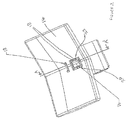
- FIG. 1 illustrates an example mobile communication device according to a preferred embodiment
- Fig. 1 illustrates a mobile communication device 10.
- the mobile communication device has an array 12 of metal keys 14, each having one or more characters engraved or etched into the surface illustrative of the function or user input associated with actuation of the key.
- the keys of this particular embodiment are made of steel although other metals could be used.
- the keys of the array of the illustrated embodiment abut with their neighbours to produce the appearance of a contoured metal sheet. Because of the abutment of adjacent keys, the key legend of the keys of the array are provided on the keys themselves. Although engraving the pattern enables the character or characters of the legend to be visible to the naked eye in daylight conditions, more difficulty in reading the information may be encountered in less favourable light.
- Illumination of the legend is made possible by a number of holes, cut outs or apertures 18 cut into the key cap directed between the outer and inner surfaces of the key tip.
- Each hole 18 allows light provided behind the key array to pass through.
- the holes can range from about 0.02 to 0.3mm in diameter.
- the exact size or shape of the holes is not critical, the term hole should be taken to include any cross-sectional shape.
- the holes should aim to be large enough to let the required amount of light through. In some embodiments it may be desirable for the holes 18 to be close enough together to provide what appears to be a seamless trace of the character when illuminated.
- the holes are ideally spaced far enough one from the other to provide bridges 22 of sufficient strength to support the island.
- the key cap 14 in this embodiment is 0.50 mm thick and the engraving extends to approximately half the thickness, the holes being drilled or punctured through the other half.
- the thickness of bridges 22 may be of the order of 0.10 mm, also subject to the size of the island to be supported such that larger islands 20 require a stronger support which can be provided by increasing the thickness of the bridges 22 and / or the thickness of the key cap 14 and / or by reducing the depth of the engraving.
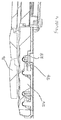
- the back lighting in the illustrated embodiment is provided by side firing LEDs 24 located between the keys.
- a diffuse and uniform light is provided by firing these LEDs into a translucent key mat 26 that is located between the keys and switches 36.
- the key mat has recesses 28 in which the LEDs 24 are located.
- LEDs are placed in the recesses 28 ( Fig. 4 ) in the key mat at a number of locations 29 ( Fig. 5 ) for the LEDs 24 ( Figs. 4 , 6 ) mainly between the keys where they do not interfere with mechanical operation of the keys.
- the key mat has switch protrusions 34 located respectively in register with each key cap 14 and transparent intervening parts 40 have been attached to the key caps between the key cap and the switch protrusion 34.
- the depression or actuation of the key results in the intervening part 40 relaying the actuation force to the key mat by its switch protrusion 34 deforming the key mat 32 to depress the switch 36.
- the transparent intervening parts 40 also guide light from the key mat to the holes 18.
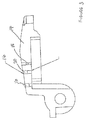
- the engraved character may be filled with a translucent resin as illustrated in Figure 3 .
- the translucent resin may provide the additional effect of acting as a diffuser for the light giving an increased angle of visibility.
- the resin is preferably treated such that it will fill entirely the engraved character without substantially entering to the holes 18.
- the resin bridging over the mouths of holes 18 will typically define an arched air-to-resin interface which will also cause diffusion to the back light passing through the resin.
- the illuminable key legends 16 are formed from through drilled holes 18, in this embodiment, blind holes may be used if the material remaining allows sufficient passage of light.
- embodiments of the invention are particularly useful for metal keys which are not readily illuminated by back lighting, the same technique for illuminating keys could be used for any opaque or semi-opaque material.
- the characters instead of illuminating traces of characters, the characters may be indicated by arranging corresponding illumination to areas surrounding solid traces of characters such that the characters will appear as non-illuminated regions against illumination surrounding them.
Landscapes
- Engineering & Computer Science (AREA)
- Signal Processing (AREA)
- Push-Button Switches (AREA)
- Input From Keyboards Or The Like (AREA)
- Telephone Set Structure (AREA)
Description
- This invention relates to a key for a mobile communication device. The invention relates particularly, but not exclusively, to illuminated key caps for mobile communication devices.
- Various mobile devices have keys for receiving user input such as text, numbers or user commands. Such keys often contain a legend printed on a key cap, as in a wired or wireless telephone or Personal Digital Assistant (PDA) device. It is very common to illuminate such legends, particularly for mobile communication devices, by forming a key cap at least partly of a light conductive material and providing an Illuminator behind the key cap so that an associated legend can be seen even without any ambient light. For instance, Nokia™ 6110 mobile telephone contained a key mat, which formed all the key caps to a telephone keypad. The key mat was made of a light conducting rubber or plastics and coated with black relatively opaque material that was then cut by a laser to form the necessary legends to the keys, hence forming white legends on black background. These legends contained the digits, alphabets and the asterisk and hatch signs. Nokia 5110 mobile telephone also had a light conducting key mat, but instead of carving to an opaque key surface, opaque material was deposited on the key surface to form the legends, hence providing black legends on a white background.
- Common to both of these mobile phones, the legends are formed continuous as in ordinary writing. Either the legends or their background is illuminated so that the legends can be seen as an illuminated or non-illuminated surface.
-
US 2001/0032779 discloses a method of etching a character into a metal layer of a key. -
WO 2004/075224 discloses a key having one or more openings formed on its outer surface or an inner surface. The openings may remain unfilled and/or may be filled with a transparent, translucent and/or opaque material, to form a symbol. -
GB 2,311,748 -
US 2002/101738 discloses an apparatus and method of perforating the cover layer or soft skin of an automotive trim panel, such as an instrument panel, with a laser to allow light to bleed through the perforations. -
JP 62 123693 U6 - According to a first aspect of the invention there is provided a mobile device, comprising a key as defined in attached independent claim 1.
- According to a second aspect of the invention there is provided a method as defined in attached independent claim 8. Further, preferred features may be found in the dependent claims appended thereto
- It should be appreciated that the embodiments of any one aspect may produce corresponding advantages when combined with different other aspects as well and that they can be combined where applicable,
- The invention will now be described, by way of example only, with reference to the accompanying drawings, in which:
Fig. 1 illustrates an example mobile communication device according to a preferred embodiment; -
Fig. 2 illustrates a key cap of the mobile communication device ofFig. 1 in more detail; -
Fig. 3 illustrates a detail of a section of the key ofFig. 2 along the line A-A'; -
Fig. 4 is a section through the key array ofFigure 1 ; -
Fig. 5 is a perspective view of a circuit board carrying the switches illustrated inFigure 4 and showing the location of light sources; and -
Fig. 6 is illustrates a section of two abutting keys ofFig. 1 showing respectively registered two key caps and switches. -
Fig. 1 illustrates a mobile communication device 10. - The mobile communication device has an
array 12 ofmetal keys 14, each having one or more characters engraved or etched into the surface illustrative of the function or user input associated with actuation of the key. The keys of this particular embodiment are made of steel although other metals could be used. - The keys of the array of the illustrated embodiment abut with their neighbours to produce the appearance of a contoured metal sheet. Because of the abutment of adjacent keys, the key legend of the keys of the array are provided on the keys themselves. Although engraving the pattern enables the character or characters of the legend to be visible to the naked eye in daylight conditions, more difficulty in reading the information may be encountered in less favourable light.
- Illumination of the legend is made possible by a number of holes, cut outs or
apertures 18 cut into the key cap directed between the outer and inner surfaces of the key tip. Eachhole 18 allows light provided behind the key array to pass through. By providing a string or set of such holes, tracing the engravedcharacter 16, the whole character is illuminated by the back lighting. This can be seen most clearly inFigure 2 . For the present embodiment the holes can range from about 0.02 to 0.3mm in diameter. The exact size or shape of the holes is not critical, the term hole should be taken to include any cross-sectional shape. The holes should aim to be large enough to let the required amount of light through. In some embodiments it may be desirable for theholes 18 to be close enough together to provide what appears to be a seamless trace of the character when illuminated. For characters having central islands 20, the holes are ideally spaced far enough one from the other to provide bridges 22 of sufficient strength to support the island. Thekey cap 14 in this embodiment is 0.50 mm thick and the engraving extends to approximately half the thickness, the holes being drilled or punctured through the other half. For such an embodiment, the thickness of bridges 22 may be of the order of 0.10 mm, also subject to the size of the island to be supported such that larger islands 20 require a stronger support which can be provided by increasing the thickness of the bridges 22 and / or the thickness of thekey cap 14 and / or by reducing the depth of the engraving. - By using the same size and spacing of the holes along the extent of the trace defining an individual character provides for uniform illumination. This can be replicated for each key in the key array.
- Next turning to
Figs. 4 to 6 , the back lighting in the illustrated embodiment is provided by side firing LEDs 24 located between the keys. A diffuse and uniform light is provided by firing these LEDs into a translucent key mat 26 that is located between the keys and switches 36. The key mat has recesses 28 in which the LEDs 24 are located. In order to provide a reasonably uniform diffuse light for all the keys of the array, LEDs are placed in the recesses 28 (Fig. 4 ) in the key mat at a number of locations 29 (Fig. 5 ) for the LEDs 24 (Figs. 4 ,6 ) mainly between the keys where they do not interfere with mechanical operation of the keys. The key mat hasswitch protrusions 34 located respectively in register with eachkey cap 14 and transparentintervening parts 40 have been attached to the key caps between the key cap and theswitch protrusion 34. The depression or actuation of the key results in the interveningpart 40 relaying the actuation force to the key mat by itsswitch protrusion 34 deforming thekey mat 32 to depress theswitch 36. The transparent interveningparts 40 also guide light from the key mat to theholes 18. - To prevent the ingress of dirt through the tiny holes the engraved character may be filled with a translucent resin as illustrated in
Figure 3 . The translucent resin may provide the additional effect of acting as a diffuser for the light giving an increased angle of visibility. The resin is preferably treated such that it will fill entirely the engraved character without substantially entering to theholes 18. The resin bridging over the mouths ofholes 18 will typically define an arched air-to-resin interface which will also cause diffusion to the back light passing through the resin. - Although the
illuminable key legends 16 are formed from through drilledholes 18, in this embodiment, blind holes may be used if the material remaining allows sufficient passage of light. - Although embodiments of the invention are particularly useful for metal keys which are not readily illuminated by back lighting, the same technique for illuminating keys could be used for any opaque or semi-opaque material. Further, instead of illuminating traces of characters, the characters may be indicated by arranging corresponding illumination to areas surrounding solid traces of characters such that the characters will appear as non-illuminated regions against illumination surrounding them.
- The present invention may be embodied in various forms without departing from its essential attributes. It should be appreciated that the entire detailed description describes a preferred embodiment and can be freely varied by removing, replacing or adding features of this detailed description. That the various features described are optional has not been emphasised for each feature only in sake of clarity and conciseness of the description. Furthermore, each feature disclosed in this specification (which terms includes the claims) and/or shown in the drawings may be incorporated in the invention independently of other disclosed and/or illustrated feature.
- The appended abstract as filed herewith is included in the specification by reference.
Claims (13)
- A mobile device (10), comprising:a key;at least one visual trace of a character (16), associated with the key, and defined by a plurality of holes (18) that provide spot light outlets under back illumination, the visual trace of the character further defined by a groove at a front face of the key and aligned with at least a portion of the holes (18) such that the trace is visible in daylight; andbacklight illumination means for providing the back illumination.
- A mobile device (10) as claimed in claim 1, wherein at least some of the holes have a diameter between 0.02 millimeters and 0.3 millimeters.
- A mobile device (10) as claimed in claim 1 or 2, wherein the at least one visual trace includes a first visual trace of a looped character (16) that has a central part island (20), and the first visual trace is defined by holes (18) that are spaced far enough from one another to provide bridges (22) of sufficient strength to support the central part island (20).
- A mobile device (10) as claimed in any of the preceding claims, further comprising: a light guide for guiding light from the backlight illumination means to the plurality of holes (18).
- A mobile device (10) as claimed in any of the preceding claims, wherein the at least one visual trace of a character (16) provides a legend for the key.
- A mobile device (10) as claimed in any of the preceding claims, wherein at least some of the holes (18) are blocked with a transparent material.
- A mobile device as claimed in any of the preceding claims, wherein at least some of the holes (18) have a circular cross-section.
- A method, comprising:forming at least one visual trace of a character (16), associated with a key of a mobile device (10), by defining a plurality of holes (18) that provide spot light outlets under back illumination, the visual trace of the character further defined by a groove at a front face of the key and aligned with at least a portion of the holes (18) such that the trace is visible in daylight.
- A method as claimed in claim 8, wherein the holes (18) have been drilled, punched, etched or cut.
- A method as claimed in any of claims 8 to 9, wherein at least some of the holes (18) have a diameter between 0.02 millimeters and 0.3 millimeters.
- A method as claimed in any of claims 8 to 10, wherein at least one visual trace includes a first visual trace of a looped character (16) has a central part island (20), and the first visual trace is defined by holes that are spaced far enough from one another to provide bridges (22) of sufficient strength to support the central part island (20).
- A method as claimed in any of claims 8 to 11, wherein the at least one visual trace of a character (16) provides a legend for the key.
- A method as claimed in any of claims 8 to 12, further comprising: blocking the holes (18) with a transparent material.
Applications Claiming Priority (3)
| Application Number | Priority Date | Filing Date | Title |
|---|---|---|---|
| GB0307520A GB0307520D0 (en) | 2003-04-01 | 2003-04-01 | A key for a mobile device |
| GB0307611A GB2400078B (en) | 2003-04-02 | 2003-04-02 | A key for a mobile device |
| EP04725056.8A EP1604511B1 (en) | 2003-04-01 | 2004-04-01 | Key for a mobile device |
Related Parent Applications (2)
| Application Number | Title | Priority Date | Filing Date |
|---|---|---|---|
| EP04725056.8 Division | 2004-04-01 | ||
| EP04725056.8A Division EP1604511B1 (en) | 2003-04-01 | 2004-04-01 | Key for a mobile device |
Publications (2)
| Publication Number | Publication Date |
|---|---|
| EP2259557A1 EP2259557A1 (en) | 2010-12-08 |
| EP2259557B1 true EP2259557B1 (en) | 2016-08-03 |
Family
ID=33133145
Family Applications (2)
| Application Number | Title | Priority Date | Filing Date |
|---|---|---|---|
| EP10180244.5A Expired - Lifetime EP2259557B1 (en) | 2003-04-01 | 2004-04-01 | Mobile device with illuminated keys |
| EP04725056.8A Expired - Lifetime EP1604511B1 (en) | 2003-04-01 | 2004-04-01 | Key for a mobile device |
Family Applications After (1)
| Application Number | Title | Priority Date | Filing Date |
|---|---|---|---|
| EP04725056.8A Expired - Lifetime EP1604511B1 (en) | 2003-04-01 | 2004-04-01 | Key for a mobile device |
Country Status (4)
| Country | Link |
|---|---|
| US (1) | US7674992B2 (en) |
| EP (2) | EP2259557B1 (en) |
| JP (1) | JP4195034B2 (en) |
| WO (1) | WO2004088958A1 (en) |
Families Citing this family (33)
| Publication number | Priority date | Publication date | Assignee | Title |
|---|---|---|---|---|
| US7609512B2 (en) * | 2001-11-19 | 2009-10-27 | Otter Products, Llc | Protective enclosure for electronic device |
| DE602004017025D1 (en) * | 2004-11-26 | 2008-11-20 | Sony Ericsson Mobile Comm Ab | Mobile phone with luminescent keyboard |
| US8408773B2 (en) * | 2007-03-19 | 2013-04-02 | Innotec Corporation | Light for vehicles |
| TWI336893B (en) * | 2007-11-16 | 2011-02-01 | Ichia Tech Inc | Method of manufacturing metal keypad panel with micropore array |
| US7777144B2 (en) * | 2007-11-16 | 2010-08-17 | Ichia Technologies, Inc. | Metal keypad panel structure with micropore array |
| US8984737B2 (en) | 2011-11-02 | 2015-03-24 | Blackberry Limited | Method of manufacturing keycaps of keys of a keyboard |
| US9710069B2 (en) | 2012-10-30 | 2017-07-18 | Apple Inc. | Flexible printed circuit having flex tails upon which keyboard keycaps are coupled |
| US9502193B2 (en) | 2012-10-30 | 2016-11-22 | Apple Inc. | Low-travel key mechanisms using butterfly hinges |
| US9449772B2 (en) | 2012-10-30 | 2016-09-20 | Apple Inc. | Low-travel key mechanisms using butterfly hinges |
| JP6313339B2 (en) | 2013-02-06 | 2018-04-18 | アップル インコーポレイテッド | Input / output device with dynamically adjustable appearance and function |
| WO2014193850A1 (en) | 2013-05-27 | 2014-12-04 | Apple Inc. | Low travel switch assembly |
| US9908310B2 (en) | 2013-07-10 | 2018-03-06 | Apple Inc. | Electronic device with a reduced friction surface |
| JP6068295B2 (en) * | 2013-08-29 | 2017-01-25 | 京セラ株式会社 | Character display member |
| JP2016532232A (en) | 2013-09-30 | 2016-10-13 | アップル インコーポレイテッド | Key cap with reduced thickness |
| WO2015047606A1 (en) | 2013-09-30 | 2015-04-02 | Apple Inc. | Keycaps having reduced thickness |
| US9793066B1 (en) | 2014-01-31 | 2017-10-17 | Apple Inc. | Keyboard hinge mechanism |
| US9779889B2 (en) | 2014-03-24 | 2017-10-03 | Apple Inc. | Scissor mechanism features for a keyboard |
| US9704665B2 (en) | 2014-05-19 | 2017-07-11 | Apple Inc. | Backlit keyboard including reflective component |
| US9715978B2 (en) | 2014-05-27 | 2017-07-25 | Apple Inc. | Low travel switch assembly |
| US10796863B2 (en) | 2014-08-15 | 2020-10-06 | Apple Inc. | Fabric keyboard |
| US10082880B1 (en) | 2014-08-28 | 2018-09-25 | Apple Inc. | System level features of a keyboard |
| US9870880B2 (en) | 2014-09-30 | 2018-01-16 | Apple Inc. | Dome switch and switch housing for keyboard assembly |
| US9997308B2 (en) | 2015-05-13 | 2018-06-12 | Apple Inc. | Low-travel key mechanism for an input device |
| US9997304B2 (en) | 2015-05-13 | 2018-06-12 | Apple Inc. | Uniform illumination of keys |
| JP6637070B2 (en) | 2015-05-13 | 2020-01-29 | アップル インコーポレイテッドApple Inc. | Keyboard for electronic device |
| CN205959841U (en) | 2015-05-13 | 2017-02-15 | 苹果公司 | Electronics and keyboard assemblies |
| US9934915B2 (en) | 2015-06-10 | 2018-04-03 | Apple Inc. | Reduced layer keyboard stack-up |
| US9971084B2 (en) | 2015-09-28 | 2018-05-15 | Apple Inc. | Illumination structure for uniform illumination of keys |
| US10353485B1 (en) | 2016-07-27 | 2019-07-16 | Apple Inc. | Multifunction input device with an embedded capacitive sensing layer |
| US10115544B2 (en) | 2016-08-08 | 2018-10-30 | Apple Inc. | Singulated keyboard assemblies and methods for assembling a keyboard |
| US10755877B1 (en) | 2016-08-29 | 2020-08-25 | Apple Inc. | Keyboard for an electronic device |
| US11500538B2 (en) | 2016-09-13 | 2022-11-15 | Apple Inc. | Keyless keyboard with force sensing and haptic feedback |
| CN117270637A (en) | 2017-07-26 | 2023-12-22 | 苹果公司 | Computer with keyboard |
Citations (1)
| Publication number | Priority date | Publication date | Assignee | Title |
|---|---|---|---|---|
| JPS62123693U (en) * | 1986-01-27 | 1987-08-06 |
Family Cites Families (25)
| Publication number | Priority date | Publication date | Assignee | Title |
|---|---|---|---|---|
| JPS5844056B2 (en) | 1979-01-18 | 1983-09-30 | 株式会社クボタ | Method for manufacturing noncombustible construction boards |
| US4370532A (en) * | 1981-02-23 | 1983-01-25 | Illinois Tool Works Inc. | Lighted electrical pushbutton switch |
| JPS6210666A (en) | 1985-07-09 | 1987-01-19 | Konishiroku Photo Ind Co Ltd | Both sides copying device |
| DE3736116A1 (en) * | 1987-10-26 | 1989-05-11 | Preh Elektro Feinmechanik | KEY COVER FOR A KEYBOARD |
| JPH0313202A (en) | 1989-06-09 | 1991-01-22 | Furukawa Electric Co Ltd:The | Formation of fin and rugged surface of welded heat transfer pipe |
| US5266949A (en) * | 1990-03-29 | 1993-11-30 | Nokia Mobile Phones Ltd. | Lighted electronic keyboard |
| JPH0413987A (en) | 1990-05-07 | 1992-01-17 | Toyo Umpanki Co Ltd | Approach alarm device |
| FI88345C (en) | 1991-01-29 | 1993-04-26 | Nokia Mobile Phones Ltd | BELYST KEYBOARD |
| JPH05174657A (en) | 1991-12-19 | 1993-07-13 | Pioneer Electron Corp | Switch operational button and manufacture thereof |
| JPH0615227A (en) | 1992-06-30 | 1994-01-25 | Mazda Motor Corp | Painting method |
| JPH0650192A (en) | 1992-07-30 | 1994-02-22 | Toyota Motor Corp | Air-fuel ratio controller |
| JPH07329111A (en) | 1994-06-13 | 1995-12-19 | Yamashita Denki Kk | Two-color molding method using different materials resin |
| JP3612818B2 (en) | 1995-10-06 | 2005-01-19 | 信越ポリマー株式会社 | Two-piece cover member for pushbutton switch |
| GB2311748B (en) | 1996-04-04 | 1999-10-06 | Dewhurst Plc | Improvements in or relating to indicating devices |
| GB2345193B (en) | 1998-12-22 | 2002-07-24 | Nokia Mobile Phones Ltd | Metallic keys |
| US6217183B1 (en) | 1999-09-15 | 2001-04-17 | Michael Shipman | Keyboard having illuminated keys |
| DE10011800B4 (en) | 2000-03-14 | 2007-11-29 | Robert Bosch Gmbh | lighting device |
| US6576856B2 (en) | 2000-03-24 | 2003-06-10 | Polymatech Co., Ltd. | Sheet shaped key top |
| FR2812966B1 (en) * | 2000-08-11 | 2002-12-20 | Telecomm Electronique Aeronaut | MULTI-MESSAGE LUMINOUS BUTTON WITH INDEPENDENT LIGHTS, ESPECIALLY FOR AERONAUTICAL EQUIPMENT FACADE, AND BAR CONSISTING OF SUCH BUTTONS |
| US6704004B1 (en) | 2000-08-17 | 2004-03-09 | Nokia Mobile Phones Ltd. | Arrangement for integration of key illumination into keymat of portable electronic devices |
| US6652128B2 (en) | 2001-01-31 | 2003-11-25 | Textron Automotive Company, Inc. | Backlighting method for an automotive trim panel |
| JP2002232547A (en) | 2001-02-01 | 2002-08-16 | Mitsubishi Electric Corp | Illuminated keys and portable radios |
| US6498311B1 (en) * | 2001-06-29 | 2002-12-24 | Microsoft Corporation | Multi-layer keys with translucent outer layer |
| JP2003086045A (en) | 2001-09-11 | 2003-03-20 | Alps Electric Co Ltd | Button key and input device with button key |
| US7379720B2 (en) * | 2003-02-20 | 2008-05-27 | Sony Ericsson Mobile Communications Ab | Keypad lighting using polymer light emitting devices |
-
2004
- 2004-03-30 US US10/814,694 patent/US7674992B2/en not_active Expired - Fee Related
- 2004-04-01 JP JP2005518697A patent/JP4195034B2/en not_active Expired - Fee Related
- 2004-04-01 WO PCT/EP2004/050413 patent/WO2004088958A1/en not_active Ceased
- 2004-04-01 EP EP10180244.5A patent/EP2259557B1/en not_active Expired - Lifetime
- 2004-04-01 EP EP04725056.8A patent/EP1604511B1/en not_active Expired - Lifetime
Patent Citations (1)
| Publication number | Priority date | Publication date | Assignee | Title |
|---|---|---|---|---|
| JPS62123693U (en) * | 1986-01-27 | 1987-08-06 |
Also Published As
| Publication number | Publication date |
|---|---|
| JP2006521664A (en) | 2006-09-21 |
| JP4195034B2 (en) | 2008-12-10 |
| EP1604511B1 (en) | 2014-01-01 |
| US20040214618A1 (en) | 2004-10-28 |
| WO2004088958A1 (en) | 2004-10-14 |
| EP2259557A1 (en) | 2010-12-08 |
| EP1604511A1 (en) | 2005-12-14 |
| US7674992B2 (en) | 2010-03-09 |
Similar Documents
| Publication | Publication Date | Title |
|---|---|---|
| EP1604511B1 (en) | Key for a mobile device | |
| US6677931B2 (en) | Keyboard | |
| US7271360B2 (en) | Key button structure and portable terminal device therewith | |
| KR101035816B1 (en) | Key Unit with Reinforcement Plate | |
| KR100464975B1 (en) | A metal dome sheet and keypad for a mobile phone | |
| EP1906632A2 (en) | Mobile phone with illuminated touch screen | |
| DE102007003271A1 (en) | Keyboard arrangement and mobile terminal equipped therewith | |
| CN101494130A (en) | Method for manufacturing key panel with multiple groups of micropores | |
| CN101427332B (en) | Illuminating of an electrical device | |
| KR100728830B1 (en) | Film layer and method for altering the appearance of a mobile station | |
| US5734137A (en) | Universal keypad assembly | |
| US6674854B1 (en) | Telephone terminal device | |
| KR20110091511A (en) | Illuminated Key Sheet and Push Button Switches | |
| JP2008130506A (en) | Key base, key sheet provided with the same, and key unit provided with the same | |
| KR101518066B1 (en) | Flexible printed circuit board, input module and mobile apparatus | |
| JP4113784B2 (en) | Pushbutton switch member and manufacturing method thereof | |
| CN1768522B (en) | Keys for mobile devices | |
| US20120171414A1 (en) | Apparatus and Method for a User Input Element in an Electronic Device | |
| GB2400078A (en) | Key cap for a mobile communication device having back illumination | |
| CN201117495Y (en) | Key panel structure with lateral lighting key surface | |
| US20120111704A1 (en) | Apparatus and Method for a User Input Element in an Electronic Device | |
| CN100440898C (en) | mobile phone | |
| JP2000331554A (en) | Three-dimensional pattern of key top in illuminated key and method of manufacturing the same | |
| KR20030041609A (en) | Keypad device in a mobile phone | |
| KR200446649Y1 (en) | Keypad assembly with light guide plate sheet and light guide plate sheet |
Legal Events
| Date | Code | Title | Description |
|---|---|---|---|
| PUAI | Public reference made under article 153(3) epc to a published international application that has entered the european phase |
Free format text: ORIGINAL CODE: 0009012 |
|
| AC | Divisional application: reference to earlier application |
Ref document number: 1604511 Country of ref document: EP Kind code of ref document: P |
|
| AK | Designated contracting states |
Kind code of ref document: A1 Designated state(s): AT BE BG CH CY CZ DE DK EE ES FI FR GB GR HU IE IT LI LU MC NL PL PT RO SE SI SK TR |
|
| 17P | Request for examination filed |
Effective date: 20110607 |
|
| 17Q | First examination report despatched |
Effective date: 20130214 |
|
| RAP1 | Party data changed (applicant data changed or rights of an application transferred) |
Owner name: VERTU CORPORATION LIMITED |
|
| GRAP | Despatch of communication of intention to grant a patent |
Free format text: ORIGINAL CODE: EPIDOSNIGR1 |
|
| INTG | Intention to grant announced |
Effective date: 20160309 |
|
| GRAS | Grant fee paid |
Free format text: ORIGINAL CODE: EPIDOSNIGR3 |
|
| GRAA | (expected) grant |
Free format text: ORIGINAL CODE: 0009210 |
|
| AC | Divisional application: reference to earlier application |
Ref document number: 1604511 Country of ref document: EP Kind code of ref document: P |
|
| AK | Designated contracting states |
Kind code of ref document: B1 Designated state(s): AT BE BG CH CY CZ DE DK EE ES FI FR GB GR HU IE IT LI LU MC NL PL PT RO SE SI SK TR |
|
| REG | Reference to a national code |
Ref country code: GB Ref legal event code: FG4D |
|
| REG | Reference to a national code |
Ref country code: CH Ref legal event code: EP Ref country code: AT Ref legal event code: REF Ref document number: 817983 Country of ref document: AT Kind code of ref document: T Effective date: 20160815 |
|
| REG | Reference to a national code |
Ref country code: IE Ref legal event code: FG4D |
|
| REG | Reference to a national code |
Ref country code: DE Ref legal event code: R096 Ref document number: 602004049715 Country of ref document: DE |
|
| REG | Reference to a national code |
Ref country code: NL Ref legal event code: MP Effective date: 20160803 |
|
| REG | Reference to a national code |
Ref country code: AT Ref legal event code: MK05 Ref document number: 817983 Country of ref document: AT Kind code of ref document: T Effective date: 20160803 |
|
| PG25 | Lapsed in a contracting state [announced via postgrant information from national office to epo] |
Ref country code: FI Free format text: LAPSE BECAUSE OF FAILURE TO SUBMIT A TRANSLATION OF THE DESCRIPTION OR TO PAY THE FEE WITHIN THE PRESCRIBED TIME-LIMIT Effective date: 20160803 Ref country code: IT Free format text: LAPSE BECAUSE OF FAILURE TO SUBMIT A TRANSLATION OF THE DESCRIPTION OR TO PAY THE FEE WITHIN THE PRESCRIBED TIME-LIMIT Effective date: 20160803 Ref country code: NL Free format text: LAPSE BECAUSE OF FAILURE TO SUBMIT A TRANSLATION OF THE DESCRIPTION OR TO PAY THE FEE WITHIN THE PRESCRIBED TIME-LIMIT Effective date: 20160803 |
|
| PG25 | Lapsed in a contracting state [announced via postgrant information from national office to epo] |
Ref country code: SE Free format text: LAPSE BECAUSE OF FAILURE TO SUBMIT A TRANSLATION OF THE DESCRIPTION OR TO PAY THE FEE WITHIN THE PRESCRIBED TIME-LIMIT Effective date: 20160803 Ref country code: AT Free format text: LAPSE BECAUSE OF FAILURE TO SUBMIT A TRANSLATION OF THE DESCRIPTION OR TO PAY THE FEE WITHIN THE PRESCRIBED TIME-LIMIT Effective date: 20160803 Ref country code: PL Free format text: LAPSE BECAUSE OF FAILURE TO SUBMIT A TRANSLATION OF THE DESCRIPTION OR TO PAY THE FEE WITHIN THE PRESCRIBED TIME-LIMIT Effective date: 20160803 Ref country code: GR Free format text: LAPSE BECAUSE OF FAILURE TO SUBMIT A TRANSLATION OF THE DESCRIPTION OR TO PAY THE FEE WITHIN THE PRESCRIBED TIME-LIMIT Effective date: 20161104 Ref country code: PT Free format text: LAPSE BECAUSE OF FAILURE TO SUBMIT A TRANSLATION OF THE DESCRIPTION OR TO PAY THE FEE WITHIN THE PRESCRIBED TIME-LIMIT Effective date: 20161205 Ref country code: ES Free format text: LAPSE BECAUSE OF FAILURE TO SUBMIT A TRANSLATION OF THE DESCRIPTION OR TO PAY THE FEE WITHIN THE PRESCRIBED TIME-LIMIT Effective date: 20160803 |
|
| PG25 | Lapsed in a contracting state [announced via postgrant information from national office to epo] |
Ref country code: RO Free format text: LAPSE BECAUSE OF FAILURE TO SUBMIT A TRANSLATION OF THE DESCRIPTION OR TO PAY THE FEE WITHIN THE PRESCRIBED TIME-LIMIT Effective date: 20160803 Ref country code: EE Free format text: LAPSE BECAUSE OF FAILURE TO SUBMIT A TRANSLATION OF THE DESCRIPTION OR TO PAY THE FEE WITHIN THE PRESCRIBED TIME-LIMIT Effective date: 20160803 |
|
| REG | Reference to a national code |
Ref country code: DE Ref legal event code: R097 Ref document number: 602004049715 Country of ref document: DE |
|
| PG25 | Lapsed in a contracting state [announced via postgrant information from national office to epo] |
Ref country code: CZ Free format text: LAPSE BECAUSE OF FAILURE TO SUBMIT A TRANSLATION OF THE DESCRIPTION OR TO PAY THE FEE WITHIN THE PRESCRIBED TIME-LIMIT Effective date: 20160803 Ref country code: DK Free format text: LAPSE BECAUSE OF FAILURE TO SUBMIT A TRANSLATION OF THE DESCRIPTION OR TO PAY THE FEE WITHIN THE PRESCRIBED TIME-LIMIT Effective date: 20160803 Ref country code: BG Free format text: LAPSE BECAUSE OF FAILURE TO SUBMIT A TRANSLATION OF THE DESCRIPTION OR TO PAY THE FEE WITHIN THE PRESCRIBED TIME-LIMIT Effective date: 20161103 Ref country code: SK Free format text: LAPSE BECAUSE OF FAILURE TO SUBMIT A TRANSLATION OF THE DESCRIPTION OR TO PAY THE FEE WITHIN THE PRESCRIBED TIME-LIMIT Effective date: 20160803 Ref country code: BE Free format text: LAPSE BECAUSE OF FAILURE TO SUBMIT A TRANSLATION OF THE DESCRIPTION OR TO PAY THE FEE WITHIN THE PRESCRIBED TIME-LIMIT Effective date: 20160803 |
|
| PLBE | No opposition filed within time limit |
Free format text: ORIGINAL CODE: 0009261 |
|
| STAA | Information on the status of an ep patent application or granted ep patent |
Free format text: STATUS: NO OPPOSITION FILED WITHIN TIME LIMIT |
|
| 26N | No opposition filed |
Effective date: 20170504 |
|
| PG25 | Lapsed in a contracting state [announced via postgrant information from national office to epo] |
Ref country code: SI Free format text: LAPSE BECAUSE OF FAILURE TO SUBMIT A TRANSLATION OF THE DESCRIPTION OR TO PAY THE FEE WITHIN THE PRESCRIBED TIME-LIMIT Effective date: 20160803 |
|
| REG | Reference to a national code |
Ref country code: DE Ref legal event code: R119 Ref document number: 602004049715 Country of ref document: DE |
|
| REG | Reference to a national code |
Ref country code: CH Ref legal event code: PL |
|
| GBPC | Gb: european patent ceased through non-payment of renewal fee |
Effective date: 20170401 |
|
| REG | Reference to a national code |
Ref country code: IE Ref legal event code: MM4A |
|
| REG | Reference to a national code |
Ref country code: FR Ref legal event code: ST Effective date: 20171229 |
|
| PG25 | Lapsed in a contracting state [announced via postgrant information from national office to epo] |
Ref country code: DE Free format text: LAPSE BECAUSE OF NON-PAYMENT OF DUE FEES Effective date: 20171103 Ref country code: MC Free format text: LAPSE BECAUSE OF FAILURE TO SUBMIT A TRANSLATION OF THE DESCRIPTION OR TO PAY THE FEE WITHIN THE PRESCRIBED TIME-LIMIT Effective date: 20160803 Ref country code: FR Free format text: LAPSE BECAUSE OF NON-PAYMENT OF DUE FEES Effective date: 20170502 |
|
| PG25 | Lapsed in a contracting state [announced via postgrant information from national office to epo] |
Ref country code: CH Free format text: LAPSE BECAUSE OF NON-PAYMENT OF DUE FEES Effective date: 20170430 Ref country code: LU Free format text: LAPSE BECAUSE OF NON-PAYMENT OF DUE FEES Effective date: 20170401 Ref country code: LI Free format text: LAPSE BECAUSE OF NON-PAYMENT OF DUE FEES Effective date: 20170430 Ref country code: GB Free format text: LAPSE BECAUSE OF NON-PAYMENT OF DUE FEES Effective date: 20170401 |
|
| PG25 | Lapsed in a contracting state [announced via postgrant information from national office to epo] |
Ref country code: IE Free format text: LAPSE BECAUSE OF NON-PAYMENT OF DUE FEES Effective date: 20170401 |
|
| PG25 | Lapsed in a contracting state [announced via postgrant information from national office to epo] |
Ref country code: HU Free format text: LAPSE BECAUSE OF FAILURE TO SUBMIT A TRANSLATION OF THE DESCRIPTION OR TO PAY THE FEE WITHIN THE PRESCRIBED TIME-LIMIT; INVALID AB INITIO Effective date: 20040401 |
|
| PG25 | Lapsed in a contracting state [announced via postgrant information from national office to epo] |
Ref country code: CY Free format text: LAPSE BECAUSE OF NON-PAYMENT OF DUE FEES Effective date: 20160803 |
|
| PG25 | Lapsed in a contracting state [announced via postgrant information from national office to epo] |
Ref country code: TR Free format text: LAPSE BECAUSE OF FAILURE TO SUBMIT A TRANSLATION OF THE DESCRIPTION OR TO PAY THE FEE WITHIN THE PRESCRIBED TIME-LIMIT Effective date: 20160803 |