EP2259520A1 - Process for computing a frequency offset for a UMTS communication system based on the CPICH pilot signals - Google Patents

Process for computing a frequency offset for a UMTS communication system based on the CPICH pilot signals Download PDF

Info

Publication number
EP2259520A1
EP2259520A1 EP09368017A EP09368017A EP2259520A1 EP 2259520 A1 EP2259520 A1 EP 2259520A1 EP 09368017 A EP09368017 A EP 09368017A EP 09368017 A EP09368017 A EP 09368017A EP 2259520 A1 EP2259520 A1 EP 2259520A1
Authority
EP
European Patent Office
Prior art keywords
exp
txd
notxd
conj
accordance
Prior art date
Legal status (The legal status is an assumption and is not a legal conclusion. Google has not performed a legal analysis and makes no representation as to the accuracy of the status listed.)
Withdrawn
Application number
EP09368017A
Other languages
German (de)
French (fr)
Inventor
Issam Toufik
Andrea Ancora
Current Assignee (The listed assignees may be inaccurate. Google has not performed a legal analysis and makes no representation or warranty as to the accuracy of the list.)
ST Ericsson SA
Original Assignee
ST Ericsson SA
Priority date (The priority date is an assumption and is not a legal conclusion. Google has not performed a legal analysis and makes no representation as to the accuracy of the date listed.)
Filing date
Publication date
Application filed by ST Ericsson SA filed Critical ST Ericsson SA
Priority to EP09368017A priority Critical patent/EP2259520A1/en
Priority to PCT/EP2010/003335 priority patent/WO2010139458A1/en
Priority to US13/322,629 priority patent/US8255000B2/en
Priority to EP10728118.0A priority patent/EP2438727B1/en
Priority to KR1020117028836A priority patent/KR101683937B1/en
Publication of EP2259520A1 publication Critical patent/EP2259520A1/en
Withdrawn legal-status Critical Current

Links

Images

Classifications

    • HELECTRICITY
    • H04ELECTRIC COMMUNICATION TECHNIQUE
    • H04LTRANSMISSION OF DIGITAL INFORMATION, e.g. TELEGRAPHIC COMMUNICATION
    • H04L27/00Modulated-carrier systems
    • H04L27/0014Carrier regulation
    • HELECTRICITY
    • H04ELECTRIC COMMUNICATION TECHNIQUE
    • H04LTRANSMISSION OF DIGITAL INFORMATION, e.g. TELEGRAPHIC COMMUNICATION
    • H04L25/00Baseband systems
    • H04L25/02Details ; arrangements for supplying electrical power along data transmission lines
    • H04L25/0202Channel estimation
    • H04L25/0224Channel estimation using sounding signals
    • HELECTRICITY
    • H04ELECTRIC COMMUNICATION TECHNIQUE
    • H04LTRANSMISSION OF DIGITAL INFORMATION, e.g. TELEGRAPHIC COMMUNICATION
    • H04L27/00Modulated-carrier systems
    • H04L27/0014Carrier regulation
    • H04L2027/0044Control loops for carrier regulation
    • H04L2027/0063Elements of loops
    • H04L2027/0065Frequency error detectors

Definitions

  • the invention relates to the field of wireless communication and more particularly to a process for estimating the frequency offset in third generation wireless communication systems, particularly for UMTS.
  • Universal Mobile Telecommunications Systems is based on the W-CDMA technology and is in the heart of the 3G communication networks providing packet based transmission of text, digitized voice, and multimedia data at rates up to 2 Megabits per second.
  • one base station of such a communication systems may comprise two emitting antennas each transmitting one signal comprising one corresponding Common Pilot CHannel (CPICH).
  • CPICH Common Pilot CHannel
  • Figure 1 This figure represents the pattern of the transmitted CPICH pilots' sequence.
  • ⁇ f is the frequency offset
  • T is the time duration between two consecutive samples
  • ⁇ 0 is an initial phase rotation
  • This maximum range is given by ⁇ ⁇ f ⁇ 1 2 ⁇ T , where T is the time between two consecutive CPICH pilots.
  • T is the time between two consecutive CPICH pilots.
  • UMTS T 1 15 ⁇ 10 - 3 seconds, which corresponds to covering a range of frequency offsets from minus to plus 7500 Hz.
  • DS direct-sequence
  • the use of the average tends to attenuate the effect of noise by averaging over several symbols.
  • the use of the average tends to attenuate the effect of noise by averaging over several symbols.
  • the invention also provides a process for processing the CPICH pilot signals r(i) received from the two antennas of a base station which involves the steps:
  • the invention is particularly suitable for the achievement of a UMTS receiver of a User Equipment (UE) such as a mobile telephone or a Portable Document Assistant.
  • UE User Equipment
  • the invention can be implemented in digital electronic circuitry forming a mobile telephone or a Portable Digital Assistant (PDA) including hardware circuits with a combination of firmware and software.
  • PDA Portable Digital Assistant
  • the method which is proposed is based on the computation of the phase discriminator, that is to say the sum of the autocorrelation of the samples sequence.
  • Figure 1 illustrates the sign pattern (applied to (1+j)) resulting from those formulas.
  • h m [k] is the channel gain from antenna m at time instant k
  • n[k] is the additive Gaussian noise with zero mean and variance ⁇ 2 .
  • ⁇ f corresponds to the frequency offset and assumed to be identical for both antennas.
  • the method is based on a separation of the received pilot signals from the two transmit antennas - summarized in figure 3 - in order to keep the sampling period of the resulting samples equal to T , which is a condition for keeping a relatively wide estimation of frequency offsets.
  • m 1,2
  • the two discrimators values R even,avr and R odd,avr are accumulated as follows:
  • a step 21 the process extracts the received CPICH signal included in the CPICH channel.
  • the signal received at the antenna of the user equipment is properly equalized, de-spreaded and descrambled in accordance with the W-CDMA standard. Such operations are well known to a skilled man and, therefore, do not need further development. It suffices to recall that the received despreaded signal is modulated with the appropriate code in order to extract the predetermined CPICH channel. Such channel generates the sum of the two pilot signals transmitted by the base station.
  • step 21 two parallel sequences are performed in order to separate the two pilot channels, with a left branch based on steps 22-23 and a right branch based on steps 24-25-26.
  • Such second intermediate value corresponds to the computation of R r NoTxd r NoTxd [ k ] mentioned above.
  • Step 26 achieves the computation of R r Txd r Txd [k] mentioned above
  • a step 27 the process proceeds with the computation of a sixth and seventh intermediate values, respectively Z and Z' which are computed as follows:
  • Z 2 ⁇ k y 2 ⁇ k + y ⁇ 2 ⁇ k
  • Z ⁇ ⁇ 2 ⁇ k + 1 y ⁇ 2 ⁇ k + 1 + y ⁇ ⁇ 2 ⁇ k + 1
  • the method which was described above shows a sampling period of T, which allows coverage of possible estimation range for a value of ⁇ ⁇ f ⁇ 1 2 ⁇ T
  • FIGS 4 , 5 and 6 are comparative flow charts allowing comparison of the process of the invention which was described above (and referred to as scheme n°3) with respect of two prior art method, namely scheme 1 and 2.
  • RMSE Root Mean Squared Error
  • scheme 2- a prior art method - referred to as scheme 2-only have limited performances to FO ⁇ 3500Hz since this estimator cannot estimate larger FOs.
  • the curve which is represented highlights the expected behaviors of the different estimators.
  • estimator 3 (which is the one of the invention) shows degraded performances around 1875Hz and 5625 Hz which is equivalent to the degradation shown by scheme 2 around 3.5KHz.
  • our proposed estimator has performance very close to those of estimator 2 for small FOs, which corresponds to the working regime after the AFC loop convergence.
  • Estimator 2 has the advantage of covering a much larger interval.
  • the considered SPW simulations setups are as follows:

Landscapes

  • Engineering & Computer Science (AREA)
  • Computer Networks & Wireless Communication (AREA)
  • Signal Processing (AREA)
  • Power Engineering (AREA)
  • Mobile Radio Communication Systems (AREA)

Abstract

Process for computing an estimation of the frequency offset in a receiver for a UMTS communication network said receiver receives the signal transmitted by two antennas and including two Common Pllot CHannels (CPICH), said process involving the steps of separating the two signals by means of the computation of r NoTxd k = r k + r ¢ k + 2 = 1 + j ¢ S 1 k + - 1 ŒŠ k + 1 2 Œ‹ ¢ D 2 k + N s k r Txd k = - 1 ŒŠ k + 1 2 Œ‹ ¢ r k - r ¢ k + 2 = 1 + j ¢ S 2 k + - 1 ŒŠ k + 1 2 Œ‹ ¢ D 1 k + - 1 ŒŠ k + 1 2 Œ‹ ¢ N d k Where for m = 1,2 S m k = h m ¢ exp j ¢ Õ 0 ¢ exp jk ¢ ¦ + exp j ¢ k + 2 ¢ ¦ , D m 2 ¢ k = h m ¢ exp j ¢ Õ 0 ¢ exp jk ¢ ¦ - exp j ¢ k + 2 ¢ ¦ N s k = n k + n ¢ k + 2 N d k = n k - n ¢ k + 2 h m corresponding to the channel response for antenna m ( m=1, 2 ) , j corresponding to the imaginary complex such as j 2 = -1 and ¦ = 2 À ” f T .

Description

    Technical field
  • The invention relates to the field of wireless communication and more particularly to a process for estimating the frequency offset in third generation wireless communication systems, particularly for UMTS.
  • Background Art
  • Universal Mobile Telecommunications Systems (UMTS) is based on the W-CDMA technology and is in the heart of the 3G communication networks providing packet based transmission of text, digitized voice, and multimedia data at rates up to 2 Megabits per second.
  • One particular case of UMTS is defined in the 3G specification, where one base station of such a communication systems may comprise two emitting antennas each transmitting one signal comprising one corresponding Common Pilot CHannel (CPICH). The transmitted sequence of pilots from each antenna is constructed by applying a sign pattern given by figure 1 to the symbol(1+j), where j is to the imaginary complex such as j 2 = -1.
  • Figure 1: This figure represents the pattern of the transmitted CPICH pilots' sequence.
  • Those two pilot signals which are transmitted by the base station are used for the determination of the channel characteristics but also for estimating the frequency offset between the base station reference clock and the internal clock of the User Equipment (UE). The received signal corresponding to the transmission of the kth pilot sample in the absence of frequency offset is given by: r k = 1 + j h 1 k + - 1 k + 1 2 h 2 k + n k
    Figure imgb0001

    while when the UE is subject to a frequency offset with respect to the base station, the received signal is then r k = 1 + j h 1 k + - 1 k + 1 2 h 2 k + exp j 2 πk Δ fT + φ 0 n k
    Figure imgb0002
  • Where hm [k] corresponds to the channel response from antenna m (m=1, 2) and at the time instant of transmission of the kth pilot, Δf is the frequency offset, T is the time duration between two consecutive samples and ϕ0 is an initial phase rotation.
  • Some techniques are already known for computing an estimation of the frequency offset based on the computation of phase discriminator.
  • However, the techniques which are known do not achieve both accuracy in the estimation of the offset and still operate in a relatively wide range of frequency offsets.
  • It is particularly desirable to be able to estimate an offset in the maximum range allowed by an estimation based on the CPICH, while providing accuracy in the estimation. This maximum range is given by Δ f 1 2 T ,
    Figure imgb0003
    where T is the time between two consecutive CPICH pilots. In UMTS T = 1 15 10 - 3
    Figure imgb0004
    seconds, which corresponds to covering a range of frequency offsets from minus to plus 7500 Hz.
  • Such is the goal of the present invention.
  • Summary of the invention
  • It is an object of the present invention to provide an efficient frequency offset estimation method which is suitable for direct-sequence (DS) spread-spectrum systems and particularly for the 3GPP UMTS standard.
  • It is a further object of the present invention to provide a method which provides both accuracy and wide range of estimation of the frequency offset.
  • It is another object of the present invention to provide a receiver for a UMST communication system which incorporates improved frequency offset estimation mechanisms.
  • These and other objects of the invention are achieved by means of a process for computing an estimation of the frequency offset which involves the steps of separating at the receiver the two pilot signals transmitted from the two antennas by means of the computation of r NoTxd k = r k + r k + 2 = 1 + j S 1 k + - 1 k + 1 2 D 2 k + N s k
    Figure imgb0005
    r Txd k = - 1 k + 1 2 r k - r k + 2 = 1 + j S 2 k + - 1 k + 1 2 D 1 k + - 1 k + 1 2 N d k
    Figure imgb0006
  • Where rNoTxd and rTxd are the received pilot signals from antenna 1 and from antenna 2 respectively, assuming that the channel does not change (i.e. h 1[k]=h 1 and h 2[k] = h 2) and where for m = 1,2 : S m k = h m exp j φ 0 exp jk Φ + exp j k + 2 Φ ,
    Figure imgb0007
    D m 2 k = h m exp j φ 0 exp jk Φ - exp j k + 2 Φ
    Figure imgb0008
    N s k = n k + n k + 2
    Figure imgb0009
    N d k = n k - n k + 2
    Figure imgb0010

    and Φ=2πΔfT
    we then compute R r NoTxd r NoTxd k = r NoTxd k * conj r NoTxd k + 1
    Figure imgb0011
    R r Txd r Txd k = r Txd k * conj r Txd k + 1
    Figure imgb0012

    where conj(.) is the complex conjugate operator.
  • With the assumption that the channel does not change (i.e. h 1[k]=h ¡ and h 2[k]= h 2) and after simplification, we have R r NoTxd r NoTxd k = 2 R S 1 S 1 + - 1 k + 1 2 - 1 k + 2 2 R D 2 D 2 + - 1 k + 2 2 R S 1 D 2 + - 1 k + 1 2 R D 2 S 1 + R N s N s k
    Figure imgb0013
    R r Txd r Txd k = 2 R S 2 S 2 + - 1 k + 1 2 - 1 k + 2 2 R D 1 D 1 + - 1 k + 2 2 R S 2 D 1 + - 1 k + 1 2 R D 1 S 2 + - 1 k + 1 2 - 1 k + 2 2 R N d N d k
    Figure imgb0014

    where, for m = 1,2 and n = 1,2 R S m S m = S m k . conj S m k + 1 = 2 h m 2 exp j Φ 1 + cos 2 Φ
    Figure imgb0015
    R D m D m = D m k . conj D m k + 1 = 2 h m 2 exp j Φ 1 - cos 2 Φ
    Figure imgb0016
    R S m D n = S m k . conj D n k + 1 = - 2 j h m h n * exp j Φ sin 2 Φ
    Figure imgb0017
    R N s N s = N s k . conj N s k + 1
    Figure imgb0018
    R N d N d = N d k . conj N d k + 1
    Figure imgb0019
  • In one embodiment, the estimation is based on one estimator Reven,avr computed in accordance with the following formulas: R even , avr = 1 N 2 - N 1 k = N 1 , k even N 2 R r Txd r Txd k + R r NoTxd r NoTxd k
    Figure imgb0020

    which simplifies to : R even , avr = 4 exp j Φ h 1 2 + h 2 2 cos 2 Φ + 1 N 2 - N 1 k = N 1 , k even N 2 R N s N s k - R N d N d k
    Figure imgb0021

    where N 1 and N 2 are respectively the indices of the first and the last CPICH symbols used for the frequency offset estimation. The use of the average tends to attenuate the effect of noise by averaging over several symbols.
  • The frequency offset estimate being provided by the formula: Δ f = 1 2 πT arctan m R even , avr e R even , avr
    Figure imgb0022

    where
    Figure imgb0023
    e(.) and
    Figure imgb0024
    m(.) are respectively the imaginary part and real part operators.
  • Alternatively, the frequency offset estimation is based on one estimator Rodd,avr computed in accordance with the following formulas: R odd , avr = 1 N 2 - N 1 k = N 1 , k odd N 2 R r Txd r Txd k + R r NoTxd r NoTxd k
    Figure imgb0025

    which simplifies to R odd , avr = 4 exp j Φ h 1 2 + h 2 2 + 1 N 2 - N 1 k = N 1 , k odd N 2 R N s N s k + R N d N d k
    Figure imgb0026

    where N 1 and N 2 are respectively the indices of the first and the last pilot symbols used for the frequency offset estimation. The use of the average tends to attenuate the effect of noise by averaging over several symbols.
  • The frequency offset estimate being provided by the formula: Δ f = 1 2 πT arctan m R odd , avr e R odd , avr
    Figure imgb0027
  • In one particular, embodiment, the estimation is computed on the basis of both Rodd,avr and Reven,avr in accordance with the formula:
    Figure imgb0028
    and the frequency offset estimate being provided by the formula: Δ f = 1 2 πT arctan m R e R
    Figure imgb0029
  • The invention also provides a process for processing the CPICH pilot signals r(i) received from the two antennas of a base station which involves the steps:
    • extracting the received CPICH signal included in the CPICH channel;
    • performing a first processing branch (left) comprising the steps of:
      • computing a first intermediate value x(i) in accordance with the formula: x i = r i + r i + 2
        Figure imgb0030
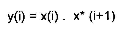
      • computing a second intermediate value y(i) derived from the first intermediate value x(i) in accordance with the formula: y i = x i . x * i + 1
        Figure imgb0031
      where x* (i+1) is the complex conjugate of x(i+1)
    • performing a second processing branch (right ) comprising the steps of:
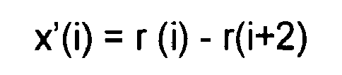
      • computing a third intermediate value x'(i) in accordance with the formula: i = r i - r i + 2
        Figure imgb0032
      • computing a fourth intermediate value t(i) derived from the third intermediate value x'(i) in accordance with the formula: 2 k = 2 k
        Figure imgb0033

        and 2 k + 1 = - 2 k + 1
        Figure imgb0034
      • computing a fifth intermediate value y'(i) derived from the fourth intermediate value t'(i) in accordance with the formula: i = i . * i + 1
        Figure imgb0035
    • computing a sixth and seventh intermediate values Z and Z' in accordance with the formulas: Z 2 k = y 2 k + 2 k
      Figure imgb0036
      2 k + 1 = y 2 k + 1 + 2 k + 1
      Figure imgb0037
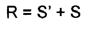
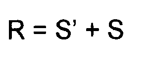
    • respectively computing an eight and a ninth values S and S' in accordance with the following formulation: S = 1 / N Σ Z k for k = 1 to N
      Figure imgb0038
      = 1 / N Σ Zʹ k for k = 1 to N
      Figure imgb0039
    • performing a test to determine whether the absolute value of the real part of S' is superior to the absolute value of the imaginary part of S' and, in that case, computing (30) a tenth intermediate value R as follows: R = + S
      Figure imgb0040
  • And, conversely if the absolute value of the real part of S' is inferior to the absolute value of the imaginary part of S', computing R in accordance with the formula: R = - S
    Figure imgb0041
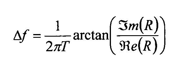
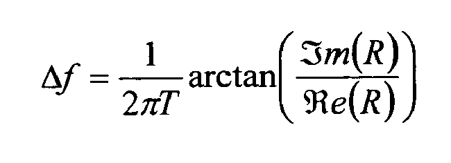
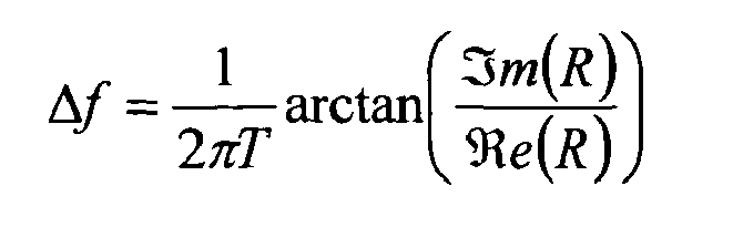
  • The offset estimation is then simply computed as follows: Δ f = 1 2 πT arctan m R e R
    Figure imgb0042

    where
    Figure imgb0043
    e(R) and
    Figure imgb0044
    m(R) are the real and imaginary parts, respectively of the tenth intermediate value R.
  • The invention is particularly suitable for the achievement of a UMTS receiver of a User Equipment (UE) such as a mobile telephone or a Portable Document Assistant.
  • Description of the drawings
  • Other features of one or more embodiments of the invention will best be understood by reference to the following detailed description when read in conjunction with the accompanying drawings.
    • Figure 1 illustrates the structure of the sign patter (applied to (1+j)) of the two CPICH pilots sequences which are used in the UMTS using transmit diversity (TxD)
    • Figure 2 illustrates one embodiment of the method for computing the offset frequency in accordance with the present invention.
    • Figure 3 illustrates the principle of the separation of the two signals transmitted through the two emitting antennas.
    • Figure 4 illustrates the Root Mean Square Error (RMSE) of the frequency offset estimation (FOE) as a function of the frequency offset (FO) for an AWGN environment and SNR=0dB
    • Figure 5 illustrates the RMSE of the frequency offset estimation as a function of lor/loc, in an AWGN environment and for FO=0Hz
    • Figure 6 illustrates the RMSE of the frequency offset as a function of lor/loc, in easel environment (defined in the 3GPP specs) and for FO=0Hz.
    Description of the preferred embodiment
  • The invention can be implemented in digital electronic circuitry forming a mobile telephone or a Portable Digital Assistant (PDA) including hardware circuits with a combination of firmware and software.
  • The method which is proposed is based on the computation of the phase discriminator, that is to say the sum of the autocorrelation of the samples sequence.
  • To simplify the mathematical treatment, we use a symbol-rate model for the CPICH symbols transmitted from Tx antenna 1 and Tx antenna 2 in symbol time instants k =0,1, ...,149 ,,,, during one 10-ms radio frame, which reads: p 1 k = 1 + j
    Figure imgb0045
    p 2 k = 1 + j - 1 k + 1 2
    Figure imgb0046
  • Figure 1 illustrates the sign pattern (applied to (1+j)) resulting from those formulas.
  • These Tx symbols are transmitted via time-varying channel coefficients to obtain the effective received symbol (on one single Rx antenna) in time instants , described by k = 0,1,.... ,149. r k h 1 k p 1 k + h 2 k p 2 k exp j 2 πk Δ fT + φ 0 + n k
    Figure imgb0047
    r k = 1 + j h 1 k + - 1 k + 1 2 h 2 k + exp j 2 πk Δ fT + φ 0 + n k
    Figure imgb0048

    where hm[k] is the channel gain from antenna m at time instant k and n[k] is the additive Gaussian noise with zero mean and variance σ2.
  • Δf corresponds to the frequency offset and assumed to be identical for both antennas.
  • The method is based on a separation of the received pilot signals from the two transmit antennas - summarized in figure 3 - in order to keep the sampling period of the resulting samples equal to T , which is a condition for keeping a relatively wide estimation of frequency offsets.
  • Now considering rNoTxd and rTxd [k] being the computed signals respectively containing only the pilot transmitted from antenna 1 and antenna 2, computed write the following formula: r NoTxd k = r k + r k + 2 = 1 + j S 1 k + - 1 k + 1 2 D 2 k + N s k
    Figure imgb0049
    r Txd k = - 1 k + 1 2 r k - r k + 2 = 1 + j S 2 k + - 1 k + 1 2 D 1 k + - 1 k + 1 2 N d k
    Figure imgb0050

    Where for m = 1,2 S m k = h m exp j φ 0 exp jk Φ + exp j k + 2 Φ
    Figure imgb0051
    D m 2 k = h m exp j φ 0 exp jk Φ - exp j k + 2 Φ
    Figure imgb0052
    N s k = n k + n k + 2
    Figure imgb0053
    N d k = n k - n k + 2
    Figure imgb0054

    hm corresponding to the channel response for antenna m (m=1, 2),
    j corresponding to the imaginary complex such as j2 = -1 and Φ = 2 π Δf T
  • It can be seen that the sampling period of rNorXd and rtd [k] sequences is T, which will allow a possible estimation range of Δ f 1 2 T
    Figure imgb0055
  • We then compute RNoTxd [k] and RTxd [k] from the separated signal rNoTxd and rTxd [k] as R r NoTxd r NoTxd k = r NoTxd k * conj r NoTxd k + 1
    Figure imgb0056
    R r Txd r Txd k = r Txd k * conj r Txd k + 1
    Figure imgb0057

    which simplifies, with the assumption that the channel is constant (i.e. h 1[k]=h 1 and h 2[k]=h2 ), to R r NoTxd r NoTxd k = 2 R S 1 S 1 + - 1 k + 1 2 - 1 k + 2 2 R D 2 D 2 + - 1 k + 2 2 R S 1 D 2 + - 1 k + 1 2 R D 2 S 1 + R N s N s k
    Figure imgb0058
    R r Txd r Txd k = 2 R S 2 S 2 + - 1 k + 1 2 - 1 k + 2 2 R D 1 D 1 + - 1 k + 2 2 R S 2 D 1 + - 1 k + 1 2 R D 1 S 2 + - 1 k + 1 2 - 1 k + 2 2 R N d N d k
    Figure imgb0059

    where, for m = 1,2 and n = 1,2 R S m S m = S m k . conj S m k + 1 = 2 h m 2 exp j Φ 1 + cos 2 Φ
    Figure imgb0060
    R D m D m = D m k . conj D m k + 1 = 2 h m 2 exp j Φ 1 - cos 2 Φ
    Figure imgb0061
    R S m D n = S m k . conj D n k + 1 = - 2 j h m h n * exp j Φ sin 2 Φ
    Figure imgb0062
    R N s N s = N s k . conj N s k + 1
    Figure imgb0063
    R N d N d = N d k . conj N d k + 1
    Figure imgb0064
  • If k is even, one may demonstrate that: R even k = R r Txd r Txd k + R r NoTxd r NoTxd k = 4 exp j Φ h 1 2 + h 2 2 cos 2 Φ + R N s N s k - R N d N d k
    Figure imgb0065
  • And if k is odd, R odd k = R r Txd r Txd k + R r NoTxd r NoTxd k = 4 exp j Φ h 1 2 + h 2 2 + R N s N s k + R N d N d k
    Figure imgb0066
  • In order to attenuate the noise effect, we compute an average over several samples of Reven [k] and Rodd [k] as R even , avr = 1 N 2 - N 1 k = N 1 , k even N 2 R even k = 4 exp j Φ h 1 2 + h 2 2 cos 2 Φ + 1 N 2 - N 1 k = N 1 , k even N 2 R N s N s k - R N d N d k
    Figure imgb0067
    R odd , avr = 1 N 2 - N 1 k = N 1 , k odd N 2 R odd k = 4 exp j Φ h 1 2 + h 2 2 + 1 N 2 - N 1 k = N 1 , k odd N 2 R N s N s k + R N d N d k
    Figure imgb0068
  • Both of these two sums Reven,avr and Rodd,avr can be considered as independent estimators and the frequency offset estimation is given respectively by Δ f = 1 2 πT arctan m R even , avr e R even , avr
    Figure imgb0069

    and Δ f = 1 2 πT arctan m R odd , avr e R odd , avr
    Figure imgb0070
  • The one based on Reven,avr is dependent on the FO due to the cos(2Φ) and is expected to show poor results around Φ = π 4 or Φ = 3 π 4
    Figure imgb0071

    (i.e. FO=±1875 or FO=±5625)
  • Also, it should be noticed that this cos(2Φ) introduces a sign inversion for Φ π 4 3 π 4
    Figure imgb0072
  • Thus, in one particular advantageous embodiment, the two discrimators values Reven,avr and Rodd,avr are accumulated as follows:
    Figure imgb0073
  • The correlation R is passed to the arctan function in order to extract the frequency offset estimate: Δ f = 1 2 πT arctan m R e R
    Figure imgb0074
  • With respect to figure 2, there is now described one particular embodiment of a method for computing the frequency offset Δf which provides both accuracy and a relatively wide range of frequency use.
  • In a step 21, the process extracts the received CPICH signal included in the CPICH channel. As known in the art, it is assumed that the signal received at the antenna of the user equipment is properly equalized, de-spreaded and descrambled in accordance with the W-CDMA standard. Such operations are well known to a skilled man and, therefore, do not need further development. It suffices to recall that the received despreaded signal is modulated with the appropriate code in order to extract the predetermined CPICH channel. Such channel generates the sum of the two pilot signals transmitted by the base station.
  • From step 21, two parallel sequences are performed in order to separate the two pilot channels, with a left branch based on steps 22-23 and a right branch based on steps 24-25-26.
  • Considering the left branch, one sees that the process proceeds to a step 22, the process proceeds with the computation of a first intermediate value x(i) in accordance with the formula: x i = r i + r i + 2
    Figure imgb0075
  • It can be seen that step 21 achieves the computation of rNoTxd [k] which was mentioned above: r NoTxd k = r k + r k + 2 = 1 + j S 1 k + - 1 k + 1 2 D 2 k + N s k
    Figure imgb0076
  • Then, in a step 23, the process proceeds with the computation of a second intermediate value y(i) derived from the first intermediate value x(i) in accordance with the formula: y i = x i . x * i + 1
    Figure imgb0077

    with x*(i+1) being the conjugate value of x(i+1).
  • Such second intermediate value corresponds to the computation of RrNoTxdrNoTxd [k] mentioned above.
  • Considering the right branch, one sees that , after completion of step 21, the process proceeds to a step 24, the process proceeds with the computation of a third intermediate value x'(i) in accordance with the formula: i = r i - r i + 2
    Figure imgb0078
  • Then, in a step 25, the process proceeds with the computation of a fourth intermediate value t(i) derived from the third intermediate value x'(i) in accordance with the formula: 2 k = 2 k
    Figure imgb0079

    and 2 k + 1 = - 2 k + 1
    Figure imgb0080
  • It can be seen that steps 24-25 achieves the computation of the value of rtxd[k] which was mentioned above: r Txd k = - 1 k + 1 2 r k - r k + 2 = 1 + j S 2 k + - 1 k + 1 2 D 1 k + - 1 k + 1 2 N d k
    Figure imgb0081
  • Then, in a step 26, the process proceeds with the computation of a fifth intermediate value y'(i) derived from the fourth intermediate value t'(i) in accordance with the formula: i = i . * i + 1
    Figure imgb0082

    where t'*(i+1) corresponds to the conjugate of the complex t'(i+1).
  • Step 26 achieves the computation of RrTxdrTxd [k] mentioned above
  • Then, in a step 27, the process proceeds with the computation of a sixth and seventh intermediate values, respectively Z and Z' which are computed as follows: Z 2 k = y 2 k + 2 k
    Figure imgb0083
    2 k + 1 = y 2 k + 1 + 2 k + 1
    Figure imgb0084
  • Then, in a step 28, the process proceeds with the average of the Z and Z' value over a period of N samples in order to respectively generate an eight and a ninth values S and S' in accordance with the following formulation: S = 1 / N Z k for k = 1 to N
    Figure imgb0085
    = 1 / N k for k = 1 to N
    Figure imgb0086
  • The process then proceeds with a step 29 which is a test for determining whether the absolute value of the real part of S' is superior to the absolute value of the imaginary part of S', in which case, the process proceeds with a step 30 where the two values S and S' are added in order to generate a tenth intermediate value R as follows: R = + S
    Figure imgb0087
  • The process then proceeds to a step 32.
  • If the absolute value of the real part of S' is inferior to the absolute value of the imaginary part of S' in step 29, the process proceeds to a step 31 where the value of S is substracted from that of S' in order to compute R in accordance with the formula: R = - S
    Figure imgb0088
  • After completion of steps 30 and 31, the process proceeds to a step 32 where the frequency offset estimation is computed as follows: Δ f = 1 2 πT arctan m R e R
    Figure imgb0089

    where
    Figure imgb0090
    e(R) and
    Figure imgb0091
    m(R) are the real and imaginary parts, respectively of the tenth intermediate value R.
  • The method which was described above shows a sampling period of T, which allows coverage of possible estimation range for a value of Δ f 1 2 T
    Figure imgb0092
  • Figures 4, 5 and 6 are comparative flow charts allowing comparison of the process of the invention which was described above (and referred to as scheme n°3) with respect of two prior art method, namely scheme 1 and 2.
  • Figures 4 represents the Root Mean Squared Error (RMSE) of the frequency offset estimate (FOE) as a function of the frequency offset (FO) for AWGN and a SNR=0dB. It should be noticed that a prior art method - referred to as scheme 2-only have limited performances to FO<3500Hz since this estimator cannot estimate larger FOs. The curve which is represented highlights the expected behaviors of the different estimators. As expected, estimator 3 (which is the one of the invention) shows degraded performances around 1875Hz and 5625 Hz which is equivalent to the degradation shown by scheme 2 around 3.5KHz. However, our proposed estimator has performance very close to those of estimator 2 for small FOs, which corresponds to the working regime after the AFC loop convergence. Estimator 2 has the advantage of covering a much larger interval.
  • Figures 5 and 6 plot the FOE' s RMSE as a function of lor/loc for FO=0Hz (for AWGN and case 1 propagation scenarios respectively).
  • The considered SPW simulations setups are as follows:
    • For AWGN:
      • Measurement Reference Channel: 12.2Kbps
      • lorx/loc=-i dB
      • DPCH-Ec/lorx= - 16.6 dB
      • loc=-60 dBm
    • For fading multi-path case1:
      • Measurement Reference Channel: 12.2Kbps lorx/loc=9 dB DPCH_Ec/lorx = - 15 dB loc = -60 dBm
      • Multi-path propagation: 2 paths
        • ○ Powers: 0dB,-10dB
        • ○ Delays: 0ns, 976ns

Claims (12)

  1. Process for computing an estimation of the frequency offset in a receiver for a UMTS communication network said receiver receives the signal transmitted by two antennas and including two Common PIlot CHannels (CPICH), said process involving the steps of separating the two signals by means of the computation of r NoTxd k = r k + r k + 2 = 1 + j S 1 k + - 1 k + 1 2 D 2 k + N s k
    Figure imgb0093
    r Txd k = - 1 k + 1 2 r k - r k + 2 = 1 + j S 2 k + - 1 k + 1 2 D 1 k + - 1 k + 1 2 N d k
    Figure imgb0094

    where for m = 1,2 S m k = h m exp j φ 0 exp jk Φ + exp j k + 2 Φ
    Figure imgb0095
    D m 2 k = h m exp j φ 0 exp jk Φ - exp j k + 2 Φ
    Figure imgb0096
    N s k = n k + n k + 2
    Figure imgb0097
    N d k = n k - n k + 2
    Figure imgb0098

    hm corresponding to the channel response for antenna m (m=1, 2),
    j corresponding to the imaginary complex such as j2 = -1 and Φ = 2 π Δf T
  2. Process according to claim 1 characterized in that the frequency offset estimation is based on one estimator Reven,avr computed in accordance with the following formulas: R even , avr = 1 N 2 - N 1 k = N 1 , k even N 2 R even k
    Figure imgb0099

    with R even k = R r Txd r Txd k + R r NoTxd r NoTxd k = 4 exp j Φ h 1 2 + h 2 2 cos 2 Φ + R N s N s k - R N d N d k
    Figure imgb0100

    in which R r NoTxd r NoTxd k = r NoTxd k * conj r NoTxd k + 1 = 2 R S 1 S 1 + - 1 k + 1 2 - 1 k + 2 2 R D 2 D 2 + - 1 k + 2 2 R S 1 D 2 + - 1 k + 1 2 R D 2 S 1 + R N s N s k
    Figure imgb0101
    R r Txd r Txd k = r Txd k * conj r Txd k + 1 = 2 R S 2 S 2 + - 1 k + 1 2 - 1 k + 2 2 R D 1 D 1 + - 1 k + 2 2 R S 2 D 1 + - 1 k + 1 2 R D 1 S 2 + - 1 k + 1 2 - 1 k + 2 2 R N d N d k
    Figure imgb0102

    where, for m = 1,2 and n = 1,2 R S m S m = S m k . conj S m k + 1 = 2 h m 2 exp j Φ 1 + cos 2 Φ
    Figure imgb0103
    R D m D m = D m k . conj D m k + 1 = 2 h m 2 exp j Φ 1 - cos 2 Φ
    Figure imgb0104
    R S m D n = S m k . conj D n k + 1 = - 2 j h m h n * exp j Φ sin 2 Φ
    Figure imgb0105
    R N s N s = N s k . conj N s k + 1
    Figure imgb0106
    R N d N d = N d k . conj N d k + 1
    Figure imgb0107

    The frequency offset estimate being provided by the formula: Δ f = 1 2 πT arctan m R e R
    Figure imgb0108
  3. Process according to claim 1 characterized in that the frequency offset estimation is based on one estimator Rodd,avr computed in accordance with the following formulas: R odd , avr = 1 N 2 - N 1 k = N 1 , k odd N 2 R odd k
    Figure imgb0109

    with R odd k = R r Txd r Txd k + R r NoTxd r NoTxd k = 4 exp j Φ h 1 2 + h 2 2 + R N s N s k + R N d N d k
    Figure imgb0110

    in which R r NoTxd r NoTxd k = r NoTxd k * conj r NoTxd k + 1 = 2 R S 1 S 1 + - 1 k + 1 2 - 1 k + 2 2 R D 2 D 2 + - 1 k + 2 2 R S 1 D 2 + - 1 k + 1 2 R D 2 S 1 + R N s N s k
    Figure imgb0111
    R r Txd r Txd k = r Txd k * conj r Txd k + 1 = 2 R S 2 S 2 + - 1 k + 1 2 - 1 k + 2 2 R D 1 D 1 + - 1 k + 2 2 R S 2 D 1 + - 1 k + 1 2 R D 1 S 2 + - 1 k + 1 2 - 1 k + 2 2 R N d N d k
    Figure imgb0112

    where, for m = 1,2 and n = 1,2 R S m S m = S m k . conj S m k + 1 = 2 h m 2 exp j Φ 1 + cos 2 Φ
    Figure imgb0113
    R D m D m = D m k . conj D m k + 1 = 2 h m 2 exp j Φ 1 - cos 2 Φ
    Figure imgb0114
    R S m D n = S m k . conj D n k + 1 = - 2 j h m h n * exp j Φ sin 2 Φ
    Figure imgb0115
    R N s N s = N s k . conj N s k + 1
    Figure imgb0116
    R N d N d = N d k . conj N d k + 1
    Figure imgb0117

    The frequency offset estimate being provided by the formula: Δ f = 1 2 πT arctan m R e R
    Figure imgb0118
  4. Process according claim 2 and claim 3 characterized in that the frequency offset estimation is computed on the basis of both Rodd,avr and Reven,avr in accordance with the formula:
    Figure imgb0119
    and the frequency offset estimate being provided by the formula: Δ f = 1 2 πT arctan m R e R
    Figure imgb0120
  5. Process for computing an estimation of the frequency offset in a receiver for a UMTS communication network said receiver receives the signal transmitted by two antennas and including two Common PIlot CHannels (CPICH), said process involving the steps of :
    - extracting (21) the received CPICH signal included in the CPICH channel;
    - performing a first processing branch (left) comprising the steps of:
    - computing (22) a first intermediate value x(i) in accordance with the formula: x i = r i + r i + 2
    Figure imgb0121
    - computing (23) a second intermediate value y(i) derived from the first intermediate value x(i) in accordance with the formula: y i = x i . x * i + 1
    Figure imgb0122
    - performing a second processing branch (right ) comprising the steps of:
    - computing (24) a third intermediate value x'(i) in accordance with the formula: i = r i - r i + 2
    Figure imgb0123
    - computing (25) a fourth intermediate value t(i) derived from the third intermediate value x'(i) in accordance with the formula: 2 k = 2 k
    Figure imgb0124

    and 2 k + 1 = - 2 k + 1
    Figure imgb0125
    - computing (26) a fifth intermediate value y'(i) derived from the fourth intermediate value t'(i) in accordance with the formula: i = i . * i + 1
    Figure imgb0126
    - computing (27) a sixth and seventh intermediate values Z and Z' in accordance with the formulas: Z 2 k = y 2 k + 2 k
    Figure imgb0127
    2 k + 1 = y 2 k + 1 + 2 k + 1
    Figure imgb0128
    - respectively computing an eight and a ninth values S and S' in accordance with the following formulation: S = 1 / N Z k for k = 1 to N
    Figure imgb0129
    = 1 / N k for k = 1 to N
    Figure imgb0130
    - performing a test (29) to determine whether the absolute value of the real part of S' is superior to the absolute value of the imaginary part of S' and, in that case, computing (30) a tenth intermediate value R as follows: R = + S
    Figure imgb0131
    And, conversely if the absolute value of the real part of S' is inferior to the absolute value of imaginary part of S', computing (31) R in accordance with the formula: R = - S
    Figure imgb0132

    Then, computing (32) the offset estimation in accordance with the formula: Δ f = 1 2 πT arctan m R e R
    Figure imgb0133

    where
    Figure imgb0134
    e(R) and
    Figure imgb0135
    m(R) are the real and imaginary parts, respectively of the tenth intermediate value R.
  6. Receiver for a UMST communication system comprising means for receiving the signals transmitted by two antennas and including two Common Pilot CHannels (CPICH), said receiving comprising means for separating the two signals based on the computation of : r NoTxd k = r k + r k + 2 = 1 + j S 1 k + - 1 k + 1 2 D 2 k + N s k
    Figure imgb0136
    r Txd k = - 1 k + 1 2 r k - r k + 2 = 1 + j S 2 k + - 1 k + 1 2 D 1 k + - 1 k + 1 2 N d k
    Figure imgb0137

    Where for m = 1,2 S m k = h m exp j φ 0 exp jk Φ + exp j k + 2 Φ
    Figure imgb0138
    D m 2 k = h m exp j φ 0 exp jk Φ - exp j k + 2 Φ
    Figure imgb0139
    N s k = n k + n k + 2
    Figure imgb0140
    N d k = n k - n k + 2
    Figure imgb0141

    hm corresponding to the channel response for antenna m (m=1, 2),
    j corresponding to the imaginary complex such as j2 = -1 and Φ = 2 π Δf T
  7. Receiver according to claim 6 characterized in that the frequency offset estimation is based on one estimator Reven,avr computed in accordance with the following formulas: R even , avr = 1 N 2 - N 1 k = N 1 , k even N 2 R even k
    Figure imgb0142

    with R even k = R r Txd r Txd k + R r NoTxd r NoTxd k = 4 exp j Φ h 1 2 + h 2 2 cos 2 Φ + R N s N s k - R N d N d k
    Figure imgb0143

    in which R r NoTxd r NoTxd k = r NoTxd k * conj r NoTxd k = 2 R S 1 S 1 + - 1 k + 1 2 - 1 k + 2 2 R D 2 D 2 + - 1 k + 2 2 R S 1 D 2 + - 1 k + 1 2 R D 2 S 1 + R N s N s k
    Figure imgb0144
    R r Txd r Txd k = r Txd k * conj r Txd k + 1 = 2 R S 2 S 2 + - 1 k + 1 2 - 1 k + 2 2 R D 1 D 1 + - 1 k + 2 2 R S 2 D 1 + - 1 k + 1 2 R D 1 S 2 + - 1 k + 1 2 - 1 k + 2 2 R N d N d k
    Figure imgb0145

    where, for m = 1,2 and n = 1,2 R S m S m = S m k . conj S m k + 1 = 2 h m 2 exp j Φ 1 + cos 2 Φ
    Figure imgb0146
    R D m D m = D m k . conj D m k + 1 = 2 h m 2 exp j Φ 1 - cos 2 Φ
    Figure imgb0147
    R S m D n = S m k . conj D n k + 1 = - 2 j h m h n * exp j Φ sin 2 Φ
    Figure imgb0148
    R N s N s = N s k . conj N s k + 1
    Figure imgb0149
    R N d N d = N d k . conj N d k + 1
    Figure imgb0150

    The frequency offset estimate being provided by the formula: Δ f = 1 2 πT arctan m R e R
    Figure imgb0151
  8. Process according to claim 6 characterized in that the frequency offset estimation is based on one estimator Rodd,avr computed in accordance with the following formulas: R odd , avr = 1 N 2 - N 1 k = N 1 , k odd N 2 R odd k
    Figure imgb0152

    with R odd k = R r Txd r Txd k + R r NoTxd r NoTxd k = 4 exp j Φ h 1 2 + h 2 2 + R N s N s k + R N d N d k
    Figure imgb0153

    in which R r NoTxd r NoTxd k = r NoTxd k * conj r NoTxd k + 1 = 2 R S 1 S 1 + - 1 k + 1 2 - 1 k + 2 2 R D 2 D 2 + - 1 k + 2 2 R S 1 D 2 + - 1 k + 1 2 R D 2 S 1 + R N s N s k
    Figure imgb0154
    R r Txd r Txd k = r Txd k * conj r Txd k + 1 = 2 R S 2 S 2 + - 1 k + 1 2 - 1 k + 2 2 R D 1 D 1 + - 1 k + 2 2 R S 2 D 1 + - 1 k + 1 2 R D 1 S 2 + - 1 k + 1 2 - 1 k + 2 2 R N d N d k
    Figure imgb0155

    where, for m = 1,2 and n =1,2 R S m S m = S m k . conj S m k + 1 = 2 h m 2 exp j Φ 1 + cos 2 Φ
    Figure imgb0156
    R D m D m = D m k . conj D m k + 1 = 2 h m 2 exp j Φ 1 - cos 2 Φ
    Figure imgb0157
    R S m D n = S m k . conj D n k + 1 = - 2 j h m h n * exp j Φ sin 2 Φ
    Figure imgb0158
    R N s N s = N s k . conj N s k + 1
    Figure imgb0159
    R N d N d = N d k . conj N d k + 1
    Figure imgb0160

    The frequency offset estimate being provided by the formula: Δ f = 1 2 πT arctan m R e R
    Figure imgb0161
  9. Receiver according to claim 7 or 8 characterized in that the frequency offset estimation is computed on the based of both Rodd,avr and Reven,avr in accordance with the formula:
    Figure imgb0162
    and the frequency offset estimate being provided by the formula: Δ f = 1 2 πT arctan m R e R
    Figure imgb0163
  10. Receiver for a UMTS communication network comprising means for receiving the signal transmitted by two antennas and including two Common Pilot CHannels (CPICH), said receiver comprising:
    - means for extracting (21) the received CPICH signal included in the CPICH channel;
    - means for performing a first processing branch (left) comprising the steps of:
    - means for computing (22) a first intermediate value x(i) in accordance with the formula: x i = r i + r i + 2
    Figure imgb0164
    - means for computing (23) a second intermediate value y(i) derived from the first intermediate value x(i) in accordance with the formula: y i = x i . x * i + 1
    Figure imgb0165
    - means for performing a second processing branch (right ) comprising the steps of:
    - means for computing (24) a third intermediate value x'(i) in accordance with the formula: i = r i - r i + 2
    Figure imgb0166
    - means for computing (25) a fourth intermediate value t(i) derived from the third intermediate value x'(i) in accordance with the formula: 2 k = 2 k
    Figure imgb0167

    and 2 k + 1 = - 2 k + 1
    Figure imgb0168
    - means for computing (26) a fifth intermediate value y'(i) derived from the fourth intermediate value t'(i) in accordance with the formula: i = i . * i + 1
    Figure imgb0169
    - means for computing (27) a sixth and seventh intermediate values Z and Z' in accordance with the formulas: Z 2 k = y 2 k + 2 k
    Figure imgb0170
    2 k + 1 = y 2 k + 1 + 2 k + 1
    Figure imgb0171
    - respectively computing an eight and a ninth values S and S' in accordance with the following formulation: S = Z k for k = 1 to N
    Figure imgb0172
    = k for k = 1 to N
    Figure imgb0173
    - means for performing a test (29) to determine whether the absolute value of the real part of S' is superior to the absolute value of the imaginary part of S' and, in that case, computing (30) a tenth intermediate value R as follows: R = + S
    Figure imgb0174
    And, conversely if the absolute value of the real part of S' is inferior to the absolute value of the imaginary part of S', means for computing (31) R in accordance with the formula: R = - S
    Figure imgb0175

    Means for computing (32) the offset estimation in accordance with the formula: Δ f = 1 2 πT arctan m R e R
    Figure imgb0176

    where Re(R) and m(R) are the real and imaginary parts, respectively of the tenth intermediate value R.
  11. Mobile telephone for a UMTS communication network comprising the receiver as defined in claim 6 to 10.
  12. Mobile telephone according to claim 11 characterized in that it is embodied in a Portable Document Assistant (PDA).
EP09368017A 2009-06-02 2009-06-02 Process for computing a frequency offset for a UMTS communication system based on the CPICH pilot signals Withdrawn EP2259520A1 (en)

Priority Applications (5)

Application Number Priority Date Filing Date Title
EP09368017A EP2259520A1 (en) 2009-06-02 2009-06-02 Process for computing a frequency offset for a UMTS communication system based on the CPICH pilot signals
PCT/EP2010/003335 WO2010139458A1 (en) 2009-06-02 2010-06-02 Process for computing a frequency offset for a umts communication system based on the cpich pilot signals
US13/322,629 US8255000B2 (en) 2009-06-02 2010-06-02 Process for computing a frequency offset for a UMTS communication system based on the CPICH pilot signals
EP10728118.0A EP2438727B1 (en) 2009-06-02 2010-06-02 Process for computing a frequency offset for a UMTS communication system based on the CPICH pilot signals
KR1020117028836A KR101683937B1 (en) 2009-06-02 2010-06-02 Process for computing a frequency offset for a umts communication system based on the cpich pilot signals

Applications Claiming Priority (1)

Application Number Priority Date Filing Date Title
EP09368017A EP2259520A1 (en) 2009-06-02 2009-06-02 Process for computing a frequency offset for a UMTS communication system based on the CPICH pilot signals

Publications (1)

Publication Number Publication Date
EP2259520A1 true EP2259520A1 (en) 2010-12-08

Family

ID=41228439

Family Applications (2)

Application Number Title Priority Date Filing Date
EP09368017A Withdrawn EP2259520A1 (en) 2009-06-02 2009-06-02 Process for computing a frequency offset for a UMTS communication system based on the CPICH pilot signals
EP10728118.0A Not-in-force EP2438727B1 (en) 2009-06-02 2010-06-02 Process for computing a frequency offset for a UMTS communication system based on the CPICH pilot signals

Family Applications After (1)

Application Number Title Priority Date Filing Date
EP10728118.0A Not-in-force EP2438727B1 (en) 2009-06-02 2010-06-02 Process for computing a frequency offset for a UMTS communication system based on the CPICH pilot signals

Country Status (4)

Country Link
US (1) US8255000B2 (en)
EP (2) EP2259520A1 (en)
KR (1) KR101683937B1 (en)
WO (1) WO2010139458A1 (en)

Families Citing this family (1)

* Cited by examiner, † Cited by third party
Publication number Priority date Publication date Assignee Title
EP2424067A1 (en) * 2010-08-26 2012-02-29 ST-Ericsson SA Power management circuit for a portable electronic device including USB functionality and method for doing the same

Citations (3)

* Cited by examiner, † Cited by third party
Publication number Priority date Publication date Assignee Title
EP1249980A2 (en) * 2001-04-09 2002-10-16 Nippon Telegraph and Telephone Corporation OFDM signal communication system, OFDM signal transmitting device and OFDM signal receiving device
JP2004072458A (en) * 2002-08-07 2004-03-04 Nippon Telegr & Teleph Corp <Ntt> Carrier frequency error estimation circuit, radio signal receiving device
US20050286611A1 (en) * 2004-06-25 2005-12-29 Nokia Corporation System, and associated method, for facilitating broadband multi-carrier transmission

Family Cites Families (9)

* Cited by examiner, † Cited by third party
Publication number Priority date Publication date Assignee Title
CA2326750C (en) * 1998-04-03 2010-03-16 Telefonaktiebolaget Lm Ericsson Flexible radio access and resource allocation in a universal mobile telephone system (umts)
JP4338526B2 (en) 2002-02-21 2009-10-07 メディアテック インコーポレーテッド 3G wireless receiver
US20040137851A1 (en) * 2002-10-29 2004-07-15 Akhter Mohammad Shahanshah Frequency offset controller
CN1820437A (en) * 2003-08-04 2006-08-16 汤姆森许可贸易公司 Frequency synchronization during cell searching in universal mobile telephone system receiver
JP4190406B2 (en) * 2003-12-25 2008-12-03 三洋電機株式会社 Frequency offset estimation method and frequency offset correction apparatus using the same
KR100594146B1 (en) * 2004-02-11 2006-06-28 삼성전자주식회사 Apparatus and method for initial frequency offset estimation in asynchronous mobile communication system
SG126808A1 (en) * 2005-05-05 2006-11-29 Oki Techno Ct Singapore Pte Frequency offset estimation for dpsk
US7899136B2 (en) * 2007-05-03 2011-03-01 Infineon Technologies Ag Frequency-offset estimation
US20100093389A1 (en) 2008-10-14 2010-04-15 Sony Ericsson Mobile Communications Ab Responding to a paging request from a gsm network by setting up the call through a umts network

Patent Citations (3)

* Cited by examiner, † Cited by third party
Publication number Priority date Publication date Assignee Title
EP1249980A2 (en) * 2001-04-09 2002-10-16 Nippon Telegraph and Telephone Corporation OFDM signal communication system, OFDM signal transmitting device and OFDM signal receiving device
JP2004072458A (en) * 2002-08-07 2004-03-04 Nippon Telegr & Teleph Corp <Ntt> Carrier frequency error estimation circuit, radio signal receiving device
US20050286611A1 (en) * 2004-06-25 2005-12-29 Nokia Corporation System, and associated method, for facilitating broadband multi-carrier transmission

Non-Patent Citations (1)

* Cited by examiner, † Cited by third party
Title
LUISE M ET AL: "Carrier frequency recovery in all-digital modems for burst-mode transmissions", IEEE TRANSACTIONS ON COMMUNICATIONS, IEEE SERVICE CENTER, PISCATAWAY, NJ, US, vol. 43, no. 2-4, 1 February 1995 (1995-02-01), pages 1169 - 1178, XP002321165, ISSN: 0090-6778 *

Also Published As

Publication number Publication date
KR101683937B1 (en) 2016-12-07
US8255000B2 (en) 2012-08-28
EP2438727B1 (en) 2013-10-23
WO2010139458A1 (en) 2010-12-09
KR20120044932A (en) 2012-05-08
US20120157162A1 (en) 2012-06-21
EP2438727A1 (en) 2012-04-11

Similar Documents

Publication Publication Date Title
US7149258B2 (en) Method and apparatus for estimation of phase offset between communication channels
CN101814931B (en) Doppler frequency shift estimation and compensation method in TD-SCDMA (Time Division-Synchronization Code Division Multiple Access) system
KR101017208B1 (en) How to determine gain offset between transmission channels
US7945007B2 (en) Multi-antenna wireless receiver chains with vector decoding
US7912162B2 (en) Initial synchronization for receivers
KR101035218B1 (en) Method and apparatus for clock correction in MIO ODM
US7929937B2 (en) System and method for blind estimation of multiple carrier frequency offsets and separation of user signals in wireless communications systems
EP1542384A1 (en) Transmission/reception apparatus and transmission/reception method
US20050276354A1 (en) IQ imbalance compensation
US20020150168A1 (en) Optimum phase error metric for OFDM pilot tone tracking in wireless LAN
US6628926B1 (en) Method for automatic frequency control
US7649964B2 (en) Radio receiver and noise estimated value correction method
US6546026B1 (en) Multi-diversity synchronization technique for improving synchronization performance in wireless applications over fading channels
JP2003529236A (en) Data rate determination based on power spectral density estimation
EP2135415B1 (en) Adaptive channel estimation
US20020176354A1 (en) Timing misalignment estimation
CN100403657C (en) TD-SCDMA system frequency offset compensating method and apparatus based on exercising sequence
EP2259520A1 (en) Process for computing a frequency offset for a UMTS communication system based on the CPICH pilot signals
US20050180518A1 (en) Preamble for estimation and equalization of asymmetries between inphase and quadrature branches in multicarrier transmission systems
JP2007019985A (en) Receiver
US7889780B2 (en) Method of estimating doppler spread and signal-to-noise ratio of a received signal
US9203526B2 (en) Method and system for improved interference cancellation by path selection
Groh et al. Low Complexity High Resolution Maximum Likelihood Channel Estimation in Spread Spectrum Navigation Systems

Legal Events

Date Code Title Description
PUAI Public reference made under article 153(3) epc to a published international application that has entered the european phase

Free format text: ORIGINAL CODE: 0009012

AK Designated contracting states

Kind code of ref document: A1

Designated state(s): AT BE BG CH CY CZ DE DK EE ES FI FR GB GR HR HU IE IS IT LI LT LU LV MC MK MT NL NO PL PT RO SE SI SK TR

AX Request for extension of the european patent

Extension state: AL BA RS

STAA Information on the status of an ep patent application or granted ep patent

Free format text: STATUS: THE APPLICATION IS DEEMED TO BE WITHDRAWN

18D Application deemed to be withdrawn

Effective date: 20110609